CP36931-18AJ
- 格式:doc
- 大小:157.00 KB
- 文档页数:2
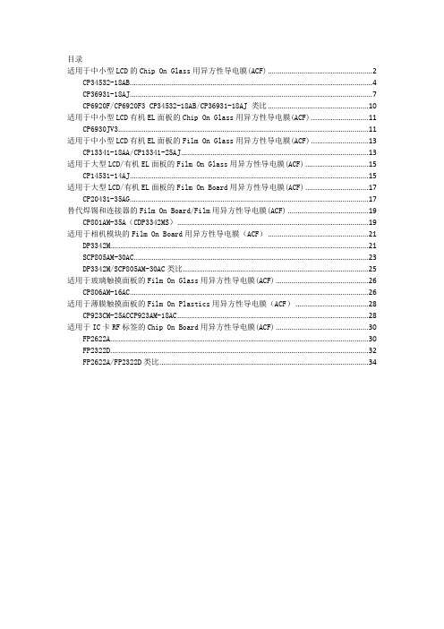
目录适用于中小型LCD的Chip On Glass用异方性导电膜(ACF) (2)CP34532-18AB (4)CP36931-18AJ (7)CP6920F/CP6920F3 CP34532-18AB/CP36931-18AJ 类比 (10)适用于中小型LCD有机EL面板的Chip On Glass用异方性导电膜(ACF) (11)CP6930JV3 (11)适用于中小型LCD有机EL面板的Film On Glass用异方性导电膜(ACF) (13)CP13341-18AA/CP13341-25AJ (13)适用于大型LCD/有机EL面板的Film On Glass用异方性导电膜(ACF) (15)CP14531-14AJ (15)适用于大型LCD/有机EL面板的Film On Board用异方性导电膜(ACF) (17)CP20431-35AG (17)替代焊锡和连接器的Film On Board/Film用异方性导电膜(ACF) (19)CP801AM-35A(CDP3342MS) (19)适用于相机模块的Film On Board用异方性导电膜(ACF) (21)DP3342M (21)SCP805AM-30AC (23)DP3342M/SCP805AM-30AC类比 (25)适用于玻璃触摸面板的Film On Glass用异方性导电膜(ACF) (26)CP806AM-16AC (26)适用于薄膜触摸面板的Film On Plastics用异方性导电膜(ACF) (28)CP923CM-25ACCP923AM-18AC (28)适用于IC卡RF标签的Chip On Board用异方性导电膜(ACF) (30)FP2622A (30)FP2322D (32)FP2622A/FP2322D类比 (34)技术规格书适用于中小型LCD的Chip On Glass用异方性导电膜(ACF)本材料拥有优异的传导性和端子间绝缘特性,特别适合进行细间距(Fine pitch)连接,可将驱动芯片(IC),直接邦定在平板显示面板的玻璃基板上。
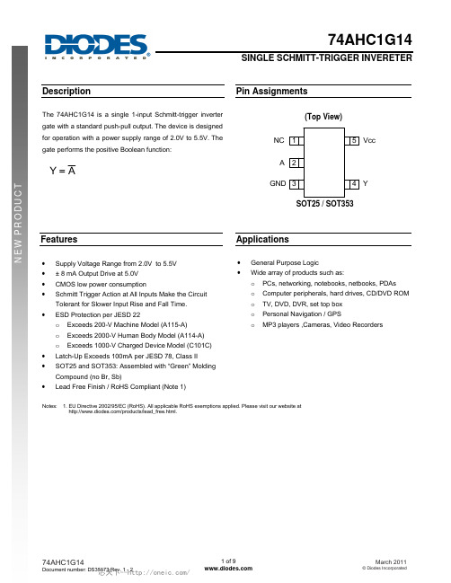
DescriptionThe 74AHC1G14 is a single 1-input Schmitt-trigger inverter gate with a standard push-pull output. The device is designed for operation with a power supply range of 2.0V to 5.5V. The gate performs the positive Boolean function:AY =Pin AssignmentsSOT25 / SOT353NCGND YVcc(Top View)AFeatures• Supply Voltage Range from 2.0V to 5.5V • ± 8 mA Output Drive at 5.0V • CMOS low power consumption• Schmitt Trigger Action at All Inputs Make the Circuit Tolerant for Slower Input Rise and Fall Time. •ESD Protection per JESD 22o Exceeds 200-V Machine Model (A115-A) o Exceeds 2000-V Human Body Model (A114-A) o Exceeds 1000-V Charged Device Model (C101C) • Latch-Up Exceeds 100mA per JESD 78, Class II • SOT25 and SOT353: Assembled with “Green” Molding Compound (no Br, Sb)• Lead Free Finish / RoHS Compliant (Note 1)Applications• General Purpose Logic •Wide array of products such as:o PCs, networking, notebooks, netbooks, PDAs o Computer peripherals, hard drives, CD/DVD ROM o TV, DVD, DVR, set top box o Personal Navigation / GPSo MP3 players ,Cameras, Video RecordersNotes: 1. EU Directive 2002/95/EC (RoHS). All applicable RoHS exemptions applied. Please visit our website at/products/lead_free.html .Pin DescriptionsPin NamePin NO.DescriptionNC 1 NoConnection A 2 Data Input GND 3 Ground Y 4 Data OutputV CC 5 Supply VoltageLogic DiagramFunction TableInputs Output AYH L L HAbsolute Maximum Ratings (Note 2)Symbol Description Rating UnitESD HBM Human Body Model ESD Protection 2 KVESD CDM Charged Device Model ESD Protection 1 KVESD MM Machine Model ESD Protection 200 V V CC Supply Voltage Range -0.5 to 6.5 VV I Input Voltage Range -0.5 to 6.5 VV O Voltage applied to output in high or low state -0.5 to V CC +0.5 VI IK Input Clamp Current V I<0 -20 mAI OK Output Clamp Current (V O < 0 or V O > V CC) ±20 mAI O Continuous output current (V O = 0 to V CC) ±25 mAI CC Continuous current through V CC 50 mAI GND Continuous current through GND -50 mAT J Operating Junction Temperature -40 to 150 °CT STG Storage Temperature -65 to 150 °CNotes: 2. Stresses beyond the absolute maximum may result in immediate failure or reduced reliability. These are stress values and device operation should bewithinrecommendvalues.Recommended Operating Conditions (Note 3)Symbol Parameter Min Max UnitV CC Operating Voltage 2 5.5 V V I Input Voltage 0 5.5 VV O Output Voltage 0 V CC VI OH High-level output current V CC = 2V -50 uA V CC = 3.3V ± 0.3V -4mAV CC = 5V ± 0.5V -8I OL Low-level output current V CC = 2V 50 uA V CC = 5V ± 0.5V 4mAV CC = 3V 8T A Operating free-airtemperature-40 125 ºCNotes: 3. Unused inputs should be held at V CC or Ground.Electrical CharacteristicsSymbol Parameter Test Conditions V CC25ºC -40ºC to 85ºC -40ºC to 125ºCUnit Min Typ. Max Min Max Min MaxV T+Positive-goinginputthresholdvoltage3V 2.2 2.2 2.2 V4.5V 3.15 3.15 3.15 V5.5V 3.85 3.85 3.85 VV T-Negative-goinginputthresholdvoltage3 V 0.9 0.9 0.9 V4.5V 1.35 1.35 1.35 V5.5V 1.65 1.65 1.65 VΔV T Hysteresis(V T+ - V T-)3V 0.3 1.2 0.3 1.2 0.25 1.2 V4.5V 0.4 1.4 0.4 1.4 0.35 1.4 V5.5V 0.5 1.6 0.5 1.6 0.45 1.6V OH High LevelOutput VoltageI OH = -50μA2V 1.9 2 1.9 1.9V3V 2.9 3 2.9 2.94.5V 4.4 4.5 4.4 4.4I OH = -4mA 3V 2.58 2.48 2.40I OH = -8mA 4.5V 3.94 3.8 3.70V OL Low LevelOutput VoltageI OL = 50μA2V 0.1 0.1 0.1V3V 0.1 0.1 0.14.5V 0.1 0.1 0.1I OL = 4mA 3V 0.36 0.44 0.55I OL = 8mA 4.5V 0.36 0.44 0.55I I Input Current V I = 5.5 V or GND 0 to 5.5V± 0.1 ± 1 ± 2 μAI CC Supply Current V I = 5.5V or GNDI O=05.5V 1 10 40 μAC I InputCapacitanceV I = V CC – orGND5.5V 2.0 10 10 10 pFθJA ThermalResistanceJunction-to-AmbientSOT25(Note 4)195o C/W SOT353 430θJC ThermalResistanceJunction-to-CaseSOT25(Note 4)58o C/W SOT353 155Note: 4. Test conditions for SOT25, and SOT353: Device mounted on FR-4 substrate PC board, 2oz copper, with minimum recommended pad layoutSwitching CharacteristicsV CC = 3.3V ± 0.3 (see Figure 1)ParameterFrom (Input) TO (OUTPUT)25ºC -40ºC to 85ºC -40ºC to 125ºCUnitMinTyp.MaxMin Max Min Maxt pdA YC L =15pF0.6 4.2 12.8 0.6 15.0 0.6 16.5 ns C L =50pF0.6 6.0 16.3 0.6 18.5 0.6 20.5 nsV CC = 5V ± 0.5V (see Figure 1)ParameterFrom (Input) TO (OUTPUT)25ºC -40ºC to 85ºC -40ºC to 125ºCUnitMinTyp.MaxMin MaxMin Maxt pdA YC L =15pF0.6 3.2 8.6 0.6 10.0 0.6 11.0 ns C L =50pF0.6 4.6 10.6 0.6 12.0 0.6 13.5 nsOperating CharacteristicsT A = 25 ºCParameterTest Conditions V CC = 5 V Unit Typ. C pdPower dissipation capacitancef = 1 MHz No Load10pFParameter Measurement InformationV CCInputsV M C LVIt r /tf3.3V±0.3VV CC ≤3ns V CC /2 15pF 5V±0.5V V CC ≤3ns V CC /2 15pF 3.3V±0.3V V CC ≤3ns V CC /2 50pF 5V±0.5VV CC≤3nsV CC /250pFVoltage Waveform Pulse DurationVoltage Waveform Propagation Delay TimesInverting and Non Inverting OutputsFigure 1. Load Circuit and Voltage WaveformsNotes: A. Includes test lead and test apparatus capacitance.B. All pulses are supplied at pulse repetition rate ≤ 1 MHz.C. Inputs are measured separately one transition per measurement.D. t PLH and t PHL are the same as t PD .Ordering Information74AHC1G 14XX -7W5:SOT25FunctionPackage7:Tape &ReelPacking 14:1-InputSchmitt-Trigger InverterSE :SOT353Logic Device 74:Logic Prefix AHC :2to Family 1G :One gate5.5VDevice Package Code Packaging (Note 5) 7” Tape and ReelQuantityPart Number Suffix74AHC1G14W5-7 W5 SOT25 3000/Tape & Reel -7 74AHC1G14SE-7SESOT3533000/Tape & Reel-7Notes: 5. Pad layout as shown on Diodes Inc. suggested pad layout document AP02001, which can be found on our website at/datasheets/ap02001.pdf.Marking InformationXX : Identification codeW : Week : A~Z : 1~26 week;X : A~Z : Internal code(Top View)Y : Year 0~9a~z : 27~52 week; z represents 52 and 53 weekPart NumberPackageIdentification Code74AHC1G14W5 SOT25 YV 74AHC1G14SE SOT353YVPackage Outline Dimensions (All Dimensions in mm) (1) Package Type: SOT25(2) Package Type: SOT353SOT25Dim Min Max TypA0.350.500.38B 1.50 1.70 1.60C 2.70 3.00 2.80D ⎯ ⎯ 0.95H 2.90 3.10 3.00J0.0130.100.05K 1.00 1.30 1.10L0.350.550.40M0.100.200.15N0.700.800.75α 0° 8° ⎯All Dimensions in mmSOT353Dim Min MaxA0.10 0.30B 1.15 1.35C 2.00 2.20D0.65 TypF0.40 0.45H 1.80 2.20J0 0.10K0.90 1.00L0.25 0.40M0.10 0.22α 0° 8°All Dimensions in mm。

派克汉尼汾公司版权所有未经许可不能摘录,翻印。
保留修改权利2021年6月警告销售条件本样本中产品和/或系统或相关产品出现故障,选型不当或使用不当,均可能导致人身伤亡和财产损失。
本文档以及由派克·汉尼汾公司及其子公司和授权经销商提供的其他资料,为具有技术知识的用户提供进一步研究所需的产品和/或系统选项。
重要的是,用户必须对您的应用进行全面的分析,并对当前产品样本中与产品或系统相关的资料进行评估。
由于工作条件以及产品或系统的多样性,用户必须自行分析和测试,并独自承担一切后果,包括:产品和系统的最终选型以及确保满足应用的所有性能、安全和警告等方面的要求。
派克·汉尼汾及其子公司可能会随时对本样本中的产品,包括但不限于:产品的特性、产品的规格、产品的结构、产品的有效性以及产品的价格作出变更而不另行通知.本样本中的所有产品均由派克·汉尼汾公司及其子公司和援权经销商销售。
与派克签订的任何销售合同均按照派克标准条件和销售条件中规定的条款执行(提供复印件备索)。
本公司的密封件,只能在本公司的文件资料述及的应用参数范围与接触介质、压力、温度和存放时间相一致的情况下才能使用。
在规定的应用参数范围外使用以及错误选用不同的材料都可能导致密封件寿命的缩短以及设备的损坏,甚至更严重的后果(如生命安全,环境污染等)。
样本中所列出的工作压力、温度范围、运动速度是极限值,它们之间相互关联、相互影响;在极端的工况下,建议不要同时把各个参数都同时用到极限值。
对于特殊的要求(压力、温度、速度、介质等),请联系派克汉尼汾公司以咨询合适的密封结构、材料、配置、安装建议等。
由于诸多工作参数会影响到流体传动系统及密封元件,这些设备的制造商必须在实际工作条件下测试、验证并批准密封系统的功能与可靠性。
此外,对于不断出现的新的介质(液压油、润滑脂、清洗剂等),用户特别注意它们与目前所用的密封件弹性体材料的兼容性。
我们建议用户在大批量应用之前,在厂内或现场先做密封材料的兼容性能测试,作为密封产品与系统供应商,我们建议用户遵循我们的这些建议。

sTest Kit, Communication Adapter, Power SupplyDispositivo de prueba Pocket de test pour11323Installation Instructions / Instructivo de InstalaciónUse only with Siemens certified Components.Utilizar únicamente con componentes certificados de Siemens.A utiliser uniquement avec les composants certifiés Siemens.Turn off and lock out all power supplying this device before Couper Tensión Tension dangereuse.Hazardous Voltage.working on this device.Replace all covers before power supplying this device is turned on.l'alimentation de l'appareil et barrer avant de travailler.Remplacez touts les couverts avant que l'approvisionnement de pouvoir soit alimenté.peligrosa.Puede causar la muerte o lesiones graves.Danger de mort ou risque de blessures graves.Will cause death or serious injury.Desenergice totalmente antes de instalar o darle servicio. Reemplace todas las barreras y cubiertas antes de energizar el interruptor.For Use With Frame DG, FG, JG, LG, MG, NG & PG Para Usar Con Caja Base DG, FG, JG, LG, MG, NG & PGU.S. Cat. No.Euro Order No.9 lb.in.[ 1.0 Nm ]UPAPELTK 3VL9000-8AL01Accessory [ Accesorio ]ELTPHB3VL9000-8AK013 x 9VItem:ELTPHB 3VL9000-8AK01Cal. ISO 67892NOTE -These instructions do not purport to cover all details or variations in equipment, or to provide for every possible contingency to be met in connection with installation, operation or maintenance. Should further information be desired or should particular problems arise, which are not covered sufficiently for the purchaser’s purposes, the matter should be referred to the local Siemens sales office. The contents of this instruction manual shall not become part of or modify any prior or existing agreement, commitment or relationship. The sales contract contains the entire obligation of Siemens. The warranty contained in the contract between the parties is the sole warranty of Siemens. Any statements contained herein do not create new warranties or modify the existing warranty.Trademarks -Unless otherwise noted, all names identified by ®are registered trademarks of Siemens AG or Siemens Industry, Inc. The remaining trademarks in this publication may be trademarks whose use by third parties for their own purposes could violate the rights of the owner.ON / I4CT Test:[ CT Prueba: ]567Option [ Opción ]ok ok2ON / I35Trip Test:[ Interrumpir Prueba ]CT Test:[ CT Prueba: ]6UPAPELTK \3VL9000-8AL01Call Technical Support [ Lamar a Soporte Técnico ]1O / OFF74I / ON12okokBattery Low Step -2POWER okokStep -289Trip Test:[ Interrumpir Prueba ]Trip Unit -545 –Only[ Disparador -545 ] -SolamenteTurn off and lock out all power supplying this device before Couper Tensión Tension dangereuse.Hazardous Voltage.working on this device.Replace all covers before power supplying this device is turned on.l'alimentation de l'appareil et barrer avant de travailler.Remplacez touts les couverts avant que l'approvisionnement de pouvoir soit alimenté.peligrosa.Puede causar la muerte o lesiones graves.Danger de mort ou risque de blessures graves.Will cause death or serious injury.Desenergice totalmente antes de instalar o darle servicio. Reemplace todas las barreras y cubiertas antes de energizar el interruptor.MINMIN1ON / I4ELTPHB 3VL9000-8AP01ON / I56Test:[ Prueba: ]7Trip [ Interrumpir ]OK 82ON / I3O / OFF9OKCall Technical Support [ Lamar a Soporte Técnico ]10Ground Fault Test:[Prueba: Falla a Tierra]Trip Unit -545 with Ground Fault –Only [ Disparador –545 con Falla a Tierra ] -Solamente11MAXMAXMAX1ON / I4ELTPHB3VL9000-8AP01ON / I56Test:[ Prueba: ]7Trip[ Interrumpir]OK82ON / I3O / OFF9OKCall Technical Support[ Lamar a Soporte Técnico ]Test Settings [ Ajuste de prueba ]Value [ Valor ]Screen [ Pantalla ]I i = 1.25 X I n AmpsI i IOC AMPS –[ AMPS SOBREC INST ]806932Setting Menus [ Menus de Ajuste ]Trip Test:[ Interrumpir Prueba ]12131ON / I4ELTPHB 3VL9000-8AP01ON / I56Test:[ Prueba: ]7Trip [ Interrumpir ]OK 82ON / I3O / OFF9OKCall Technical Support [ Lamar a Soporte Técnico ]Trip Unit -576 –Only[ Disparador -576 ] -SolamenteFor Support in Europe refer to :Bestell-Nr. / Order No.: 3ZX1012-0VL68-1AA0 Internet: www.siemens.de/lowvoltage/technical-assistance GWA 4NEB 179 6819-10 DS04Ground Fault Test:[Prueba: Falla a Tierra ]141621806932Setting Menus [ Menus de Ajuste ]3 lb. in.[ 0.3 Nm ]Option : [ Opción ]:315Test Settings [ Ajuste de prueba ]Value [ Valor ]Screen [ Pantalla ]I r = 1.0 X I n Amps I r CONTINUOUS AMPS –[ AMPERIOS CONT ]= GND RESIDUAL [ = RESIDUAL ]I iGROUND FAULT TYPE –[ TIPO FALLA TIERR-]t sd = 0.5 sec.t sd SHORT TIME DELAY –[ RETARDO CORTO ]I sd = 6 X I r Amps I sd SHORT TIME PICK UP –[ TIEMPO CORTO INICIO ]t r = 30 st r LONG TIME DELAY –[ RETARDO LARGO ]IOC AMPS –[ AMPS SOBREC INST ]I i = 6 X I n AmpsTrip Unit -576 with Ground Fault –Only [ Disparador –576 con Falla a Tierra ] -Solamente1ON / I4ELTPHB 3VL9000-8AP01ON / I56Test:[ Prueba: ]7Trip [ Interrumpir ]OK 82ON / I3O / OFF9OKCall Technical Support [ Lamar a Soporte Técnico ]1.5”[ 38 mm ]MAX.Technical Support:Toll Free: 1-800-241-4453Internet: /powerdistribution。

危险化学品名录(2002版)第3类易燃液体本表说明:1、本表只供危险化学品名录数据的参考查阅使用;具体查阅请以国家正式书面文件为准.2、《名录》全文刊于《国家安全生产监督管理局(国家煤矿安全监察局)公告2003年增刊》。
3、因本表数据的疏漏、错失而引起的相关经济法律等问题,本办公室不负任何责任。
编号名称别名UN号第1项低闪点液体31001汽油[闪点<-18℃]1203,125731002正戊烷戊烷1265310022-甲基丁烷异戊烷126531003环戊烷114631004环己烷六氢化苯114531005己烷及其异构体,如:120831005正己烷己烷1208310052—甲基戊烷异己烷1208310052,2-二甲基丁烷新己烷310052,3-二甲基丁烷二异丙基245731005己烷异构体混合物310061—戊烯1108310062-戊烯31007异戊烯,如:2371310072-甲基—1-丁烯2459 310073—甲基—1—丁烯α—异戊烯2561 310072-甲基—2-丁烯β-异戊烯2460 31008环戊烯2246310091—己烯丁基乙烯2370 310092—己烯31010己烯异构体,如:31010异己烯2288310102,3—二甲基—1-丁烯310102,3—二甲基-2-丁烯四甲基乙烯310102-甲基-1—戊烯310102—甲基—2—戊烯310103—甲基—1—戊烯310103—甲基-2—戊烯310104-甲基-1-戊烯310104—甲基-2—戊烯310102—乙基-1—丁烯31011异庚烯2287310122-甲基—1,3—丁二烯[抑制了的]异戊间二烯1218 310132—氯—1,3-丁二烯[抑制了的]199131014己二烯,如:2458310141,3—己二烯2458310141,4-己二烯2458310141,5—己二烯2458310142,4—己二烯245831015甲基戊二烯246131016二环庚二烯2,5-降冰片二烯2251310172—丁炔巴豆炔;二甲基乙炔1144310181-戊炔丙基乙炔310191-氯丙烷氯(正)丙烷;丙基氯1278310202—氯丙烷氯异丙烷;异丙基氯2356 310212—氯丙烯异丙烯基氯2456310213—氯丙烯烯丙基氯;α—氯丙烯110031022乙醛108931023异丁醛204531024丙烯醛[抑制了的]烯丙醛109231025丙酮二甲(基)酮109031026乙醚二乙(基)醚115531027正丙醚二(正)丙醚238431027异丙醚二异丙(基)醚115931028甲基丙基醚甲丙醚261231028乙基丙基醚乙丙醚261531029乙烯基乙醚[抑制了的]乙基乙烯醚130231029乙氧基乙烯31030二乙烯基醚[抑制了的]乙烯基醚116731031二甲氧基甲烷甲撑二甲醚;二甲醇缩甲醛;甲缩醛1234 310311,1-二甲氧基乙烷二甲醇缩乙醛;乙醛缩二甲醇237731031二乙氧基甲烷甲醛缩二乙醇;二乙醇缩甲醛2373310311,1—二乙氧基乙烷乙叉二乙基醚;二乙醇缩乙醛;乙缩醛1088 310321,2-环氧丙烷[抑制了的]氧化丙烯;甲基环氧乙烷128031033甲硫醚二甲硫116431034乙硫醇硫氢乙烷;巯基乙烷236331035正丙硫醇硫代正丙醇;1-巯基丙烷2402310362—丁基硫醇仲丁硫醇122831036叔丁基硫醇叔丁硫醇122831037甲酸甲酯124331038甲酸乙酯119031039亚硝酸乙酯醇溶液119431040呋喃氧杂茂2389310412—甲基呋喃230131042四氢呋喃氧杂环戊烷205631043四氢吡喃氧己环31044甲胺水溶液氨基甲烷水溶液123531045乙胺水溶液[浓度50%~70%]氨基乙烷水溶液227031046二乙胺1154310471—氨基丙烷正丙胺1277310472-氨基丙烷异丙胺1221310483—氨基丙烯烯丙胺233431049四甲基硅烷四甲基硅274931050二硫化碳113131051锆[悬浮于易燃液体中的]130831052环氧乙烷和氧化丙烯混合物[含环氧乙烷≤30%]氧化乙烯和氧化丙烯混合物2983第2项中闪点液体32001汽油[-18℃≤闪点<23℃]1203,1257 32002石油醚石油精127132003石油原油原油1267,125532004石脑油溶剂油1256,2553320053-甲基戊烷120832006正庚烷120632007庚烷异构体,如:1206320072—甲基己烷1206320073—甲基己烷1206320072,2-二甲基戊烷1206320072,3—二甲基戊烷1206320072,4—二甲基戊烷二异丙基甲烷1206 320073,3—二甲基戊烷2,2-二乙基丙烷1206 320073—乙基戊烷1206320072,2,3-三甲基丁烷120632008正辛烷126232009辛烷异构体,如:126232009异辛烷1262320092,2,4—三甲基戊烷1262 320092,3,4-三甲基戊烷1262 320092,2-二甲基己烷1262 320092,3-二甲基己烷1262 320092,4-二甲基己烷1262 320093,3—二甲基己烷1262 320093,4-二甲基己烷1262 320092—甲基庚烷1262320093-甲基庚烷1262320094-甲基庚烷1262320093-乙基己烷1262 320092—甲基—3—乙基戊烷1262 320102,2,4—三甲基己烷320102,2,5—三甲基己烷32011环戊烷衍生物,如:32011甲基环戊烷229832011乙基环戊烷320111,1—二甲基环戊烷320111,3-二甲基环戊烷32011正丙基环戊烷32012环己烷衍生物,如:32012甲基环己烷六氢(化)甲苯;环己基甲烷2296,2263 320121,1—二甲基环己烷320121,2-二甲基环己烷2263320121,3—二甲基环己烷2263320121,4—二甲基环己烷226332012叔丁基环己烷特丁基环己烷;环己基叔丁烷2263 32013环庚烷2241320143—甲基—1—丁烯异丙基乙烯2561320151-庚烯正庚烯;正戊基乙烯2278320152—庚烯320153—庚烯320161-辛烯320162-辛烯32017辛烯异构体,如:32017异辛烯1216320172,4,4—三甲基-1-戊烯2050 320172,4,4-三甲基—2—戊烯2050 32018辛二烯2309320192,6-二甲基—3-庚烯320201-甲基—1-环戊烯320211,3—环戊二烯32022环己烯1,2,3,4-四氢化苯2256 32023环己烯衍生物,如:320234-甲基-1—环己烯320234—乙烯-1-环己烯320241,3-环己二烯1,2—二氢苯320241,4-环己二烯1,4—二氢苯32025环庚烯2242320261,3,5-环庚三烯环庚三烯2603 32027环辛烯320281,3,5,7-环辛四烯环辛四烯2358 320291-己炔320292—己炔320293-己炔320301-庚炔正庚炔320311-辛炔320312-辛炔320313—辛炔320314-辛炔32032异丙烯基乙炔320331-氯丁烷正丁基氯;氯代正丁烷112732033氯代异丁烷异丁基氯320332-氯丁烷仲丁基氯;氯代仲丁烷32033氯代叔丁烷叔丁基氯;特丁基氯32034氯代正戊烷正戊基氯1107320341—氯—3—甲基丁烷异戊基氯;氯代异戊烷320351,1-二氯乙烷乙叉二氯2362320351,2—二氯乙烷乙撑二氯;亚乙基二氯;1,2—二氯化乙烯1184320361,2-二氯丙烷二氯化丙烯127932037氯化环戊烷320381—氯-2-丁烯320383-氯-1—丁烯320391-氯-2—甲基-2-丙烯2—甲基-3-氯丙烯;甲基烯丙基氯;氯化异丁烯2554320401,1-二氯乙烯[抑制了的]偏二氯乙烯1303 320401,2-二氯乙烯二氯化乙炔1150320412,3—二氯丙烯2047320422-溴丙烷异丙基溴;溴代异丙烷2344320431-溴丁烷正丁基溴;溴代正丁烷1126320431-溴—2—甲基丙烷异丁基溴;溴代异丁烷2342 320432-溴丁烷仲丁基溴;溴代仲丁烷2339320432-溴—2—甲基丙烷叔丁基溴;特丁基溴;溴代叔丁烷320441—溴—3—甲基丁烷异戊基溴;溴代异戊烷2341 320442—溴戊烷仲戊基溴;溴代仲戊烷2343320453-溴—1-丙烯烯丙其溴1099320463—溴丙炔2345320471—碘丙烷正丙基碘;碘代正丙烷2392 320472—碘丙烷异丙基碘;碘代异丙烷320481—碘—2-甲基丙烷异丁基碘;碘代异丁烷2391 320482—碘丁烷仲丁基碘;碘代仲丁烷2390320482-碘—2—甲基丙烷叔丁基碘;碘代叔丁烷320493—碘—1—丙烯烯丙基碘;碘化烯丙基1723 320493—碘—2-丙烯丙烯基碘;碘代丙烯32050苯纯苯111432050溶剂苯32051粗苯动力苯;混合苯32051重质苯32052甲基苯甲苯129432053乙基苯乙苯117532054氟代苯氟苯2387320551,2—二氟苯邻二氟苯320551,3-二氟苯间二氟苯320551,4-二氟苯对二氟苯320562-氟甲苯邻氟甲苯;邻甲(基)氟苯;2—甲(基)氟苯2388 320563-氟甲苯间氟甲苯;间甲(基)氟苯;3-甲(基)氟苯2388 320564—氟甲苯对氟甲苯;对甲(基)氟苯;4-甲(基)氟苯2388 32057三氟甲苯233832058甲醇123032059黄染料母醇10%甲醇溶液砧吨氢醇10%甲醇溶液32060甲醇钠甲醇溶液甲醇钠合甲醇128932061乙醇[无水]无水酒精117032061乙醇溶液[—18℃≤闪点<23℃]酒精溶液32061变性乙醇变性酒精32062硝化甘油乙醇溶液[含硝化甘油≤5%]1204,3064 32063乙醇钠乙醇溶液乙醇钠合乙醇320641—丙醇正丙醇1274320642-丙醇异丙醇1219320652-丙烯-1—醇烯丙醇;蒜醇1098320662—甲基-2—丙醇三甲基甲醇;特丁醇;叔丁醇1120 32067丙醛127532068正丁醛112932069正戊醛2058320693-甲基丁醛异戊醛320702-乙基丁醛二乙基乙醛1178320712-丁烯醛[抑制了的]巴豆醛;β-甲基丙烯醛1143 32072α—甲基丙烯醛异丁烯醛2396320732—丁酮乙基甲基酮;甲乙酮1193320743—甲基—2-丁酮甲基异丙基(甲)酮2397320742-戊酮甲(基)丙(基)酮1249320743-戊酮二乙(基)酮1156320753—甲基-2—戊酮甲基仲丁基(甲)酮320754-甲基-2—戊酮甲基异丁基(甲)酮;异己酮1245320752—甲基—3-戊酮乙基异丙基(甲)酮320762,4—二甲基-3—戊酮二异丙基甲酮320774-羟基-4—甲基-2—戊酮双丙酮醇1148320783—丁烯—2-酮甲基乙烯基(甲)酮;丁烯酮125132080甲基异丙烯(甲)酮[抑制了的]124632081二甲基(乙)二酮双乙酰;丁二酮234632082三氟丙酮32083甲基正丁基醚1-甲氧基丁烷;甲丁醚235032084甲基叔丁基醚239832085乙基正丁基醚乙氧基丁烷;乙丁醚117932086乙基烯丙基醚烯丙基乙基醚233532087正丁基乙烯(基)醚[抑制了的]正丁氧基乙烯;乙烯(基)正丁醚2352 32087异丁基乙烯(基)醚[抑制了的]乙烯(基)异丁醚;异丁氧基乙烯1304 32088二烯丙基醚烯丙基醚236032089氯甲基甲醚甲基氯甲醚123932090氯甲基乙醚235432091乙烯(2-氯乙基)醚(2-氯乙基)乙烯醚320922—溴乙基乙醚2340320931,2—二甲氧基乙烷乙二醇二甲醚;二甲基溶纤剂2252 320942,2—二甲氧基丙烷320953,3—二乙氧基丙烯丙烯醛二乙缩醛;二乙基缩醛丙烯醛2374 32096二氧戊环乙二醇缩甲醛1166320971,2—环氧丁烷[抑制了的]氧化丁烯3022320981,4-二氧杂环己烷二恶烷;1,4-二氧己环1165320992,5-二甲基呋喃2,5—二甲基氧(杂)茂321002-甲基四氢呋喃四氢-2-甲基呋喃253632101氧茚苯并呋喃;香豆酮;古马隆321022,3-二氢吡喃237632103四氢化吡咯吡咯烷;四氢氮杂茂192232104吡啶氮杂苯1282321051,2,5,6-四氢吡啶241032106哌啶六氢吡啶;氮己环240132107N-甲基哌啶N-甲基六氢吡啶2399321072-甲基哌啶2—甲基六氢吡啶321073-甲基哌啶3-甲基六氢吡啶321074—甲基哌啶4—甲基六氢吡啶32108N—乙基哌啶N—乙基六氢吡啶2386 32109N—甲基吗啉253532110噻吩硫杂茂;硫代呋喃241432111四氢噻吩四甲撑硫;四氢硫杂茂2412 321123—甲基噻吩甲基硫茂32113硫代乙酸硫代醋酸243632114二硫化二甲基二甲二硫;甲基化二硫2381 32115(二)乙硫醚硫代乙醚;二乙硫2375 32116正丁硫醇1—硫代丁醇2347321162-甲基-1—丙硫醇异丁硫醇321171—戊硫醇正戊硫醇1111321173—甲基—1-丁硫醇异戊硫醇321172—甲基—2—丁硫醇叔戊硫醇;特戊硫醇321172-甲基—1-丁硫醇32117戊硫醇异构体混合物321182-丙烯-1—硫醇烯丙基硫32119乙酰氯氯(化)乙酰171732120丙酰氯氯(化)丙酰181532121正丁酰氯氯(化)丁酰235332121异丁酰氯氯(化)异丁酰239532122甲酸正丙酯32122甲酸异丙酯128132123甲酸正丁酯112832123甲酸异丁酯239332124原甲酸(三)甲酯三甲氧基甲烷32125甲酸烯丙酯233632126乙酸甲酯醋酸甲酯123132127乙酸乙酯醋酸乙酯117332128乙酸正丙酯醋酸正丙酯127632128乙酸异丙酯醋酸异丙酯122032129乙酸三甲酯1,1,1—三甲氧基乙烷32130乙酸正丁酯醋酸正丁酯112332130乙酸异丁酯醋酸异丁酯32130乙酸仲丁酯醋酸仲丁酯32130乙酸叔丁酯醋酸叔丁酯32131乙酸乙烯酯[抑制了的]乙烯基乙酸酯;醋酸乙烯酯1301 32132乙酸异丙烯酯醋酸异丙烯酯240332133乙酸烯丙酯醋酸烯丙酯233332134三氟乙酸乙酯三氟醋酸乙酯32135丙酸甲酯124832136丙酸乙酯119532137丙酸异丙酯240932138丙酸异丁酯239432138丙酸仲丁酯32139丙酸烯丙酯32140正丁酸甲酯123732140异丁酸甲酯32141异丁酸乙酯238532142异丁酸异丙酯240632143正丁酸乙烯酯[抑制了的]乙烯基丁酸酯2838 32144正戊酸甲酯32144异戊酸甲酯2400321452,2—二甲基丙酸甲酯三甲基乙酸甲酯32146丙烯酸甲酯[抑制了的]191932147丙烯酸乙酯[抑制了的]191732148丁烯酸甲酯巴豆酸甲酯32148丁烯酸乙酯巴豆酸乙酯186232149异丁烯酸甲酯[抑制了的]甲基丙烯酸甲酯;牙托水;有机玻璃单体1247 32149异丁烯酸乙酯[抑制了的]甲基丙烯酸乙酯227732150氯甲酸甲酯123832151氯甲酸乙酯118232152氯甲酸异丙酯240732153亚硝酸酯类化合物,如:32153亚硝酸正丙酯32153亚硝酸异丙酯32153亚硝酸正丁酯235132153亚硝酸异丁酯235132153亚硝酸正戊酯111332153亚硝酸异戊酯111332154硝酸乙酯醇溶液32155硝酸正丙酯186532155硝酸异丙酯122232156硼酸(三)甲酯三甲氧基硼烷241632156硼酸(三)乙酯三乙氧基硼烷117631257碳酸(二)甲酯116132158钛酸(四)乙酯四乙氧基钛32158钛酸(四)正丙酯241332158钛酸(四)异丙酯32159乙腈甲基氰164832160丙腈乙基氰240432161正丁腈丙基氰241132161异丁腈异丙基氰228432162丙烯腈[抑制了的]氰(基)乙烯109332163甲基丙烯腈[抑制了的]307932164异氰酸酯类[易燃的],如:32164异氰酸甲酯248032164异氰酸乙酯248132164异氰酸正丙酯248232164异氰酸异丙酯248332164异氰酸正丁酯248532164异氰酸异丁酯248632164异氰酸叔丁酯248432164甲氧基异氰酸甲酯甲氧基甲基异氰酸酯2605 32165硫代异氰酸甲酯异硫氰酸甲酯;甲基芥子油2477 32166二甲胺溶液116032167三甲胺溶液129732168三乙胺129632169混胺-0232170二(正)丙胺238332170二异丙胺115832171N,N-二甲基丙胺226632172正丁胺1—氨基丁烷112532172异丁胺1—氨基—2—甲基丙烷121432172仲丁胺2—氨基丁烷32172叔丁胺2—氨基—2—甲基丙烷;特丁胺32173N—甲基(正)丁胺294532174二仲丁胺32175正戊胺1—氨基戊烷110632175异戊胺1-氨基—3-甲基丁烷32175仲戊胺1—甲基丁胺321761,3-二甲基丁胺2—氨基—4—甲基戊烷237932177N,N—二异丙基乙胺N—乙基二异丙胺32178N,N,N′,N′—四甲基乙二胺1,2-双(二甲基氨基)乙烷2372 32179二烯丙(基)胺235932180丙烯亚胺[抑制了的]甲基氮丙环192132181环戊胺氨基环戊烷32182六亚甲基亚胺249332183甲基肼甲基联胺1244321841,1—二甲基肼二甲基肼[不对称]1163321841,2—二甲基肼二甲基肼[对称]238232185六甲基二硅烷胺六甲基二硅亚胺32186有机硅烷化合物,如:32186甲基三氯硅烷三氯甲基硅烷125032186二甲基二氯硅烷二氯二甲基硅烷116232186三甲基氯硅烷氯化三甲基硅烷129832186乙基三氯硅烷三氯乙基硅烷119632186乙烯(基)三氯硅烷[抑制了的]三氯乙烯硅烷1305 32186二甲基二乙氧基硅烷二乙氧基二甲基硅烷238032186三甲基乙氧基硅烷乙氧基三甲基硅烷32186六甲基二硅烷32187六甲基二硅醚六甲基氧二硅烷32188正硅酸甲酯四甲氧基硅烷;硅酸四甲酯;原硅酸甲酯2606 32189二乙基硒32190硝化纤维素溶液[含氮量≤12。
Description:Ultimate protection Class J dual element,current-limiting, time-delay fuses available with optional open fuse indication. Time-delay – 10 seconds (minimum) at 500%of rated current.Catalog Symbols:LPJ-(amp)SP (non-indicating)LPJ-(amp)SPI (indicating)Ratings:Volts — 600Vac, 300Vdc Amps — 70-600AIR — 300kA Vac RMS Sym.— 100kA VdcAgency Information:CE, UL Listed, Guide JDDZ, File E4273CSA Certified, Class 1422-02, File 53787, Class J per CSA C22.2 No. 248.8,Catalog Numbers (amps) — Non-indicating Fuses*LPJ-70SP LPJ-125SP LPJ-250SP LPJ-500SP LPJ-80SP LPJ-150SP LPJ-300SP LPJ-600SPLPJ-90SP LPJ-175SP LPJ-350SP LPJ-100SP LPJ-200SP LPJ-400SP LPJ-110SPLPJ-225SPLPJ-450SP*Open fuse indication available on all part numbers by inserting the suffix “I,”e.g., LPJ-90SPI. Requires 75Vac minimum voltage.Carton Quantity:Amp Rating Carton Qty.70–2005225–6001Dimensions - in•Industry's only UL Listed and CSA Certified fuse with a 300kA interrupting rating that allows for simple, worry-freeinstallation in virtually any application.•Fast short-circuit protection and dual-element, time-delay performance provide ultimate protection.•Reduces existing fuse inventory by up to 33% when upgrading to Low-Peak fuses.•Consistent 2:1 ampacity ratios for all Low-Peak fuses make selective coordination easy.•Long time-delay minimizes needless fuse openings due to temporary overloads and transient surges.•Current-limitation protects downstream components against damaging thermal and magnetic effects of short-circuit currents.•Dual-element fuses have lower resistance than ordinary fuses so they run cooler.•Can often be sized for back-up protection against motor burnout from overload or single-phasing if other overload protective devices fail.•Proper sizing can provide "no damage" Type 2 coordinated protection for NEMA and IEC motor controllers.•Space-saving package for equipment downsizing.Recommended Fuse BlocksFuse Amps 1-Pole 2-Pole 3-Pole 70-100JM60100-1CR JM60100-2CR JM60100-3CR 110-200JM60200-1CR JM60200-2CR JM60200-3CR 225-400JM60400-1CR JM60400-2CR JM60400-3CR 450-600JM60600-1CRJM60600-2CRJM60100-3CRFor additional information on the JM Series of fuse blocks, see product brochure # 3192.Fuse Reducers For Class R FusesEquipment Desired Fuse Catalog NumbersFuse Clips (Case) Size(Pairs)60A 30A J-63100A 30A J-1360A J-16200A60AJ-26††Not for bolt-in applications.Available with easyID™open fuse indicationf C M A /F l o d y n e /H y d r a d y n e ▪ M o t i o n C o n t r o l ▪ H y d r a u l i c ▪ P n e u m a t i c ▪ E l e c t r i c a l ▪ M e c h a n i c a l ▪ (800) 426-5480 ▪ w wTime-Current Curves - Average Meltf C M A /F l o d y n e /H y d r a d y n e ▪ M o t i o n C o n t r o l ▪ H y d r a u l i c ▪ P n e u m a t i c ▪ E l e c t r i c a l ▪ M e c h a n i c a l ▪ (800) 426-5480 ▪ w wThe only controlled copy of this Data Sheet is the electronic read-only version located on the Bussmann Network Drive. All other copies of this document are by definition uncontrolled. This bulletin is intended Current-Limitation CurvesCurrent-Limiting EffectsProsp.Let-Through Current S.C.C.(Apparent RMS Symmetrical Vs. Fuse Rating)—100A 200A 400A 600A 10001000100010001000300020002000300030005000200030005000500010,000200040006000800015,000300040007000900020,00030004000700010,00025,00030005000800010,00030,00030005000800011,00035,00040005000900012,00040,00040006000900012,00050,0004000600010,00013,00060,0004000600011,00014,00080,0005000700012,00015,000100,0005000800012,00017,000150,0006000900014,00019,000200,0006000900016,00021,000250,000700010,00017,00023,000300,000700011,00018,00024,000f C M A /F l o d y n e /H y d r a d y n e ▪ M o t i o n C o n t r o l ▪ H y d r a u l i c ▪ P n e u m a t i c ▪ E l e c t r i c a l ▪ M e c h a n i c a l ▪ (800) 426-5480 ▪ w w。
LAUREL ELECTRONICS, INC.4-20 mA & Serial Output Transmitter for Resistance Input in OhmsFeatures•4-20 mA, 0-20 mA, 0-10V or -10V to +10V transmitter output, 16 bits, isolated•RS232 or RS485 serial data output, Modbus or Laurel ASCII protocol, isolated•Dual 120 mA solid state relays for alarm or control, isolated•Five precalibrated resistance input ranges from 20.000 Ω to 200.00 kΩ•Fixed 2.0000 ohm, 2.0000 MΩ and 20.000 MΩ range available as a factory specia• 1 mΩ resolution on 20 Ω scale•Custom curve linearization for changing resistance transducers•2, 3 or 4-wire connection with lead resistance compensation•Analog output resolution 0.0015% of span (16 bits), accuracy ±0.02% of span•DIN rail mount housing only 22.5 mm wide, detachable screw-clamp connectors•Universal 85-264 Vac / 90-300 Vdc or 10-48 Vdc / 12-32 Vac powerDescriptionThe Laureate Resistance Transmitter is factory calibrated forfive jumper selectable resistance ranges from 20 Ω to 200 kΩ.Fixed factory-special ranges of 2.000 Ω, 2.0000 MΩ and 20.000MΩ are also available. Accuracy is an exceptional 0.01% of fullscale ± 2 counts. Resolution is one part in 20,000. In the 20 Ωrange, resolution is 1 mΩ, making the transmitter suitable forcontact resistance and conductance measurements.Transmitter connections can be via 2, 3 or 4 wires. With 4-wirehookup, 2 wires are used for excitation and two separate wiresare used to sense the voltage across the resistance to bemeasured, thereby eliminating any lead resistance effects. With3-wire hookup, the transmitter senses the combined voltage dropacross the RTD plus two excitation leads. It also senses thevoltage drop across one excitation lead, and then subtracts twicethis voltage from the combined total. This technique effectivelysubtracts the lead resistance if the excitation leads are the same.All resistance ranges are digitally calibrated at the factory, withcalibration factors stored in EEPROM on the signal conditionerboard. This allows ranges and signal conditioner boards to bechanged in the field without recalibrating the transmitter. Ifdesired, the transmitter can easily be calibrated using externalstandards plus scale and offset in software.Fast read rate at up to 50 or 60 conversions per second whileintegrating the signal over a full power line cycle is provided byConcurrent Slope (Pat 5,262,780) analog-to-digital conversion.High read rate is ideal for peak or valley capture and for real-timecomputer interface and control.Open sensor indication is standard and may be set up to indi-cate either upscale or downscale. Excitation is provided by thetransmitter.Custom curve linearization, available with the Extendedversion, makes this transmitter ideal for use with transducerswhose output is a changing resistance.Standard features of Laureate transmitters include:•4-20 mA, 0-10V or -10V to +10V analog transmitter output,isolated, jumper-selectable and user scalable. All selectionsprovide 16-bit (0.0015%) resolution of output span and 0.02%output accuracy of a reading from -99,999 to +99,999 countsthat is also transmitted digitally. Output isolation from signaland power grounds eliminates potential ground loop problems.•Serial communications output, isolated. User selectableRS232 or RS485, half or full duplex. Three protocols are userselectable: Modbus RTU, Modbus ASCII, or Laurel ASCII.Modbus operation is fully compliant with Modbus Over SerialLine Specification V1.0 (2002). The Laurel ASCII protocolallows up to 31 Laureate devices to be addressed on thesame RS485 data line. It is simpler than the Modbus protocoland is recommended when all devices are Laureates.•Dual solid state relays, isolated. Available for local alarm orcontrol. Rated 120 mA at 130 Vac or 170 Vdc.•Universal 85-264 Vac power. Low-voltage 10-48 Vdc or 12-32 Vac power is optional.Easy Transmitter programming is via Laurel's InstrumentSetup Software, which runs on a PC under MS Windows. Thissoftware can be downloaded from this website at no charge. Therequired transmitter-to-PC interface cable is available from Laurel(P/N CBL04).SpecificationsRange Resolution Accuracy Excitation Current0-2.0000 Ω 0-20.000 Ω 0-200.00 Ω 0-2000.0 Ω 0-20000 Ω 0-200.00 kΩ 0-2.0000 MΩ 0-20.000 MΩ 0.1 mΩ1 mΩ10 mΩ100 mΩ1 Ω10 Ω100 Ω1 kΩ±0.01% of range± 2 counts5 mA5 mA500 µA50 µA5 µA500 nA500 nA75 nASignal InputInput Resolution Input Accuracy Update Rate, Max 16 bits (65,536 steps)±0.01% of full scale ± 2 counts 50/sec at 50 Hz, 60/sec at 60 HzAnalog Output (standard)Output Levels Compliance at 20 mA Compliance at 10V Output Resolution Output Accuracy Output Isolation 4-20 mA, 0-20 mA, 0-10 Vdc, -10 to +10Vdc (user selectable) 10V (0-500Ω load)2 mA (5 kΩ load or higher)16 bits (65,536 steps)0.02% of output span plus conversion accuracy250V rms working, 2.3 kV rms per 1 minute testSerial Communications (standard)Signal TypesData RatesOutput Isolation Serial Protocols Modbus Modes Modbus Compliance Digital Addressing RS232 or RS485 (half or full duplex)300, 600, 1200, 2400, 4800, 9600, 19200 baud250V rms working, 2.3 kV rms per 1 min testModbus RTU, Modbus ASCII, Laurel ASCIIRTU or ASCIIModbus over Serial Line Specification V1.0 (2002)247 Modbus addresses. Up to 32 devices on an RS485 line w/o a repeater.Dual Relay Output (standard)Relay Type Load Rating Two solid state relays, SPST, normally open, Form A 120 mA at 140 Vac or 180 VdcPower InputStandard Power Low Power Option Power Frequency Power Isolation Power Consumption 85-264 Vac or 90-300 Vdc10-48 Vdc or 12-32 VacDC or 47-63 Hz250V rms working, 2.3 kV rms per 1 min test 2W typical, 3W with max excitation outputMechanicalDimensions MountingElectrical Connections 129 x 104 x 22.5 mm case35 mm rail per DIN EN 50022 Plug-in screw-clamp connectorsEnvironmentalOperating Temperature Storage Temperature Relative Humidity Cooling Required 0°C to 55°C-40°C to 85°C95% at 40°C, non-condensingMount transmitters with ventilation holes at top and bottom. Leave 6 mm (1/4") between transmitters, or force air with a fan.PinoutMechanicalQA Application with Relays in Passband ModeA deviation limit (50 mΩ in this example) is set uparound both sides of a setpoint. The relay closes (oropens) when the reading falls within the deviationband, and opens (or closes) when the reading fallsoutside of this band. This mode sets up a passbandaround the setpoint and can be used for contactresistance testing in a production environment.RTD HookupIn 4-wire hookup, different pairs of leads are used to apply the excitation current and sense the voltage drop across the unknown resistance, so that the IR drop across the excitation leads is not a factor.In 3-wire hookup, the transmitter senses the combined voltage drop across the unknown resistance plus two excitation leads. It also senses the voltage drop across one excitation lead, and then subtracts twice this voltage from the combined total. This technique effectively subtracts all lead resistance and compen-sates for ambient temperature changes if the two excitation leads are identical.In 2-wire hookup, the transmitter senses the combined voltage drop across the unknown resistance and both lead wires. The voltage drop across the lead wires can be measured by shorting out the resistance during transmitter setup, and this voltage is then automatically subtracted from the combined total. However, changing resistance of the lead wires due to ambient tempera-ture changes will not be compensated.Ordering GuideCreate a model a model number in this format: LT20R1Transmitter Type LT Laureate 4-20 mA & RS232/RS485 output transmitter Main Board 2 Standard Main BoardPower0 Isolated 85-264 Vac or 90-300 Vdc 1 Isolated 10-48 Vdc or 12-32 VacResistance RangeR0 0-20 ohms (factory special fixed range) R1 0-20 ohms R2 0-200 ohms R3 0-2 kohms R4 0-20 kohms R5 0-200 kohmsR6 0-2 Mohms (factory special fixed range) R7 0-20 Mohms (factory special fixed range)Note: The same signal conditioner board can be used for resistance and RTD temperature measurement.AccessoriesCBL04 RS232 cable, 7ft. Connects RS232 screw terminals of LT transmitter to DB9port of PC.CBL02 USB to RS232 adapter cable. Combination of CBL02 and CBL04 connectstransmitter RS232 terminals to PC USB port.。
Eaton 121733Eaton Moeller® series PKE12 Motor-protective circuit-breaker,Complete device with standard knob, Electronic, 3 - 12 A, Withoverload releaseGeneral specificationsEaton Moeller® series PKE System-protective circuit-breaker1217334015081195435101 mm102.5 mm45 mm0.42 kgIEC/EN 60947ULCSACSA Class No.: 3211-05IEC/EN 60947-4-1CSA-C22.2 No. 60947-4-1-14 UL 60947-4-1CECSA File No.: 165628VDE 0660UL Category Control No.: NLRV UL File No.: E36332PKE12/XTU-12Product Name Catalog NumberEANProduct Length/Depth Product Height Product Width Product Weight Certifications Model CodeTurn buttonPhase-failure sensitivity (according to IEC/EN 60947-4-1, VDE 0660 Part 102)Standard knobMotor protectionPhase failure sensitiveOverload releaseMotor protection for heavy starting dutyThree-pole 1000 (Class 20) AC-4 cycle operation, Main conducting paths 700 (Class 10) AC-4 cycle operation, Main conducting paths For all combinations with an SWD activation, you need not adhere to the minimum current flow times and minimum cut-out periods.Note: Going below the minimum current flow time can cause overheating of the load (motor).500 (Class 5) AC-4 cycle operation, Main conducting paths900 (Class 15) AC-4 cycle operation, Main conducting paths≤ 500 ms, main conducting paths, AC-4 cycle operationTerminals: IP00IP2050,000 operations (at 400V, AC-3)50,000 Operations (Main conducting paths)60 Operations/h3 A12 AIII3Motor protective circuit breakerFinger and back-of-hand proof, Protection against direct contact when actuated from front (EN 50274)6000 V ACActuator type FeaturesFitted with: FunctionsNumber of poles Current flow times - minCut-out periods - minDegree of protectionLifespan, electricalLifespan, mechanicalOperating frequencyOverload release current setting - min Overload release current setting - max Overvoltage categoryPollution degreeProduct categoryProtectionRated impulse withstand voltage (Uimp)Also motors with efficiency class IE3-5 - 40 °C to IEC/EN 60947, VDE 0660 -25 - 55 °C, Operating range 25 g, Mechanical, according to IEC/EN 60068-2-27, Half-sinusoidal shock 10 msMax. 2000 m-25 °C55 °C-25 °C40 °C-40 °C80 °CDamp heat, cyclic, to IEC 60068-2-30Damp heat, constant, to IEC 60068-2-782 x (1 - 6) mm², ferrule to DIN 46228 1 x (1 - 6) mm², ferrule to DIN 462282 x (1 - 6) mm²1 x (1 - 6) mm²14 - 1010 mm 50 Hz 60 Hz 12 A 3 kWSuitable forTemperature compensation Shock resistanceAltitudeAmbient operating temperature - minAmbient operating temperature - maxAmbient operating temperature (enclosed) - minAmbient operating temperature (enclosed) - maxAmbient storage temperature - minAmbient storage temperature - maxClimatic proofingTerminal capacity (flexible with ferrule) Terminal capacity (solid)Terminal capacity (solid/stranded AWG) Stripping length (main cable)Rated frequency - minRated frequency - maxRated operational current (Ie)Rated operational power at AC-3, 220/230 V, 50 Hz Rated operational power at AC-3, 380/400 V, 50 Hz1.7 Nm, Screw terminals, Main cable 1 Nm, Screw terminals, Control circuit cables690 V690 V12 A100 A, Class J, 600 V High Fault, max. Fuse, SCCR (UL/CSA) 100 kA, 600 V High Fault, Fuse, SCCR (UL/CSA)Basic device fixed 15.5 x Iu, Trip Blocks Delayed approx. 60 ms, Trip blocks ± 20% tolerance, Trip blocks Trip block fixed 15.5 x Ir12 A, General use UL/CSA 12 A, AC-3 up to 690 V1 HP3 HP1.5 HP3 HP7.5 HP10 HPScrew terminals3.6 W0 W1.2 WRated operational voltage (Ue) - min Rated operational voltage (Ue) - max Rated uninterrupted current (Iu)Short-circuit current rating (group protection)Short-circuit releaseSwitching capacityAssigned motor power at 115/120 V, 60 Hz, 1-phase Assigned motor power at 200/208 V, 60 Hz, 3-phase Assigned motor power at 230/240 V, 60 Hz, 1-phase Assigned motor power at 230/240 V, 60 Hz, 3-phase Assigned motor power at 460/480 V, 60 Hz, 3-phase Assigned motor power at 575/600 V, 60 Hz, 3-phase Connection Equipment heat dissipation, current-dependent Pvid Heat dissipation capacity Pdiss Heat dissipation per pole, current-dependent Pvid Rated operational current for specified heat dissipation (In)0 WMeets the product standard's requirements.Meets the product standard's requirements.Meets the product standard's requirements.Meets the product standard's requirements.Meets the product standard's requirements.Does not apply, since the entire switchgear needs to be evaluated.Does not apply, since the entire switchgear needs to be evaluated.Meets the product standard's requirements.Does not apply, since the entire switchgear needs to be evaluated.Meets the product standard's requirements.Does not apply, since the entire switchgear needs to be evaluated.Does not apply, since the entire switchgear needs to be evaluated.Is the panel builder's responsibility.Is the panel builder's responsibility.Motor-Protective Circuit-Breaker PKE - brochureMotor Starters in System xStart - brochurePKE – Communication module Modbus RTUProduct Range Catalog Switching and protecting motorseaton-manual-motor-starters-pke65-characteristic-curve-003.eps 1210DIA-57eaton-manual-motor-starters-pke65-characteristic-curve.eps eaton-manual-motor-starters-pke65-characteristic-curve-005.epsDA-DC-00004945.pdfDA-DC-00004950.pdfeaton-manual-motor-starters-dimensions-002.epseaton-manual-motor-starters-mounting-3d-drawing.epseaton-manual-motor-starters-3d-drawing-002.epseaton-general-ie-ready-dilm-contactor-standards.epsETN.PKE12_XTU-12IL034011ZUIL03402019ZIL034003ZUWIN-WIN with push-in technologyVideo Motor Protective Circuit Breaker PKEMN03402004Z_DE_ENDA-CD-pke12_xtuDA-CS-pke12_xtuStatic heat dissipation, non-current-dependent Pvs10.2.2 Corrosion resistance10.2.3.1 Verification of thermal stability of enclosures10.2.3.2 Verification of resistance of insulating materials to normal heat10.2.3.3 Resist. of insul. mat. to abnormal heat/fire by internal elect. effects10.2.4 Resistance to ultra-violet (UV) radiation10.2.5 Lifting10.2.6 Mechanical impact10.2.7 Inscriptions10.3 Degree of protection of assemblies10.4 Clearances and creepage distances10.5 Protection against electric shock10.6 Incorporation of switching devices and components10.7 Internal electrical circuits and connections10.8 Connections for external conductors10.9.2 Power-frequency electric strength BrochuresCatalogues Characteristic curveDeclarations of conformity DrawingseCAD modelInstallation instructions Installation videos Manuals and user guides mCAD modelEaton Corporation plc Eaton House30 Pembroke Road Dublin 4, Ireland © 2023 Eaton. All rights reserved. Eaton is a registered trademark.All other trademarks areproperty of their respectiveowners./socialmediaIs the panel builder's responsibility.Is the panel builder's responsibility.The panel builder is responsible for the temperature rise calculation. Eaton will provide heat dissipation data for the devices.Is the panel builder's responsibility. The specifications for the switchgear must be observed.Is the panel builder's responsibility. The specifications for the switchgear must be observed.The device meets the requirements, provided the information in the instruction leaflet (IL) is observed.10.9.3 Impulse withstand voltage 10.9.4 Testing of enclosures made of insulating material 10.10 Temperature rise10.11 Short-circuit rating10.12 Electromagnetic compatibility10.13 Mechanical function。
COM Express Carrier User ManualConnect Tech Inc. 42 Arrow Road Guelph, Ontario N1K 1S6 Tel: 519-836-1291Toll: 800-426-8979 (North America only) Fax: 519-836-4878Email: ********************* ***********************Web: CTIM-00312 Revision: 0.01, September 6, 2012Connect Tech COM Express Carrier Boards - User ManualRevision 0.012 Table of ContentsCustomer Support Overview ........................................................................................................................... 4 Contact Information ........................................................................................................................................ 4 Limited Lifetime Warranty ............................................................................................................................. 5 Copyright Notice ............................................................................................................................................. 5 Trademark Acknowledgment .......................................................................................................................... 5 Revision History ............................................................................................................................................. 5 Introduction .. (6)ESD Warning ............................................................................................................................................................ 6 Product Features and Specifications .......................................................................................................................... 7 System Block Diagram . (8)Hardware Description (9)CCG0xx Carrier Board Connector Locations ............................................................................................................ 9 Top Side (9)Bottom Side ..................................................................................................................................................... 10 Jumper and Connector Summary ..................................................................................................................... 11 COM Express Module Interface .............................................................................................................................. 12 Description ...................................................................................................................................................... 12 Connector ..................................................................................................................................................... 12 Module Installation .......................................................................................................................................... 12 Module Fan Power Connector ...................................................................................................................... 12 Power ...................................................................................................................................................................... 13 Description ...................................................................................................................................................... 13 Power Connector .......................................................................................................................................... 13 COM Express Carrier Current Sourcing Capabilities ................................................................................... 13 Current Consumption information................................................................................................................ 14 Power Supply Control .................................................................................................................................. 14 +5V Standby selection ................................................................................................................................. 15 PCI-104 and PC/104 Express Expansion ................................................................................................................ 16 Description ...................................................................................................................................................... 16 PCI-104 and PC/104 Express connectors ..................................................................................................... 16 PCIe/104 Connector ........................................................................................................................................ 16 Video ....................................................................................................................................................................... 17 Description ...................................................................................................................................................... 17 HDMI .............................................................................................................................................................. 17 HDMI Connector.......................................................................................................................................... 17 LVDS Video .................................................................................................................................................... 18 Description ................................................................................................................................................... 18 LVDS Video Header .................................................................................................................................... 18 LVDS Backlight ........................................................................................................................................... 19 LVDS Backlight connector .......................................................................................................................... 19 LVDS Backlight Power Jumper ................................................................................................................... 19 Power for LVDS Panel Circuits ................................................................................................................... 19 LVDS backlight enable polarity ................................................................................................................... 20 VGA ................................................................................................................................................................ 20 VGA Pinouts ................................................................................................................................................ 20 USB 2.0 ................................................................................................................................................................... 21 Description ...................................................................................................................................................... 21 Connector ..................................................................................................................................................... 21 Compact Flash Interface .......................................................................................................................................... 21 Compact Flash Connector ............................................................................................................................ 21 Audio Interface .. (22)Connect Tech COM Express Carrier Boards - User Manual Audio Connectors (22)Audio Selection Jumpers (22)Audio Jumpering Examples (23)SATA (23)Description (23)SATA HDD Connectors (23)SATA HDD Power Connectors (24)mSATA Socket (24)10/100/1000 Ethernet (24)Description (24)10/100/1000 Ethernet RJ Connector (25)Standard Serial (26)Description (26)Serial Connector RS232 (26)Serial Connector RS485 (27)RS485 Control Jumpers (27)RS485 Schematic Snippit (28)Status LEDs (28)J4 Miscellaneous Power Control Jumpers (29)Typical Hardware Installation for +12V power input (30)Software Installation & Configuration (30)Operating System Notes (30)Linux (30)Windows (30)Cables & Interconnect (31)Mechanical (32)Devkit standoffs (32)Devkit (DEV005) parts list (32)Devkit Installation Example (33)Hole Sizes (33)COM Express Carrier Board Dimensions (34)Revision 0.01 3Connect Tech COM Express Carrier Boards - User ManualRevision 0.014 Customer Support OverviewIf you experience difficulties after reading the manual and/or using the product, contact the Connect Tech reseller from which you purchased the product. In most cases the reseller can help you with product installation and difficulties.In the event that the reseller is unable to resolve your problem, our highly qualified support staff can assist you. Our support section is available 24 hours a day, 7 days a week on our website at:/sub/support/support.asp. See the contact information section below for more information on how to contact us directly. Our technical support is always free.Contact InformationMail/Courier Connect Tech Inc. Technical Support 42 Arrow Road Guelph, Ontario Canada N1K 1S6Email/Internet********************************************Telephone/FacsimileTechnical Support representatives are ready to answer your call Monday through Friday, from 8:30 a.m. to 5:00 p.m. Eastern Standard Time. Our numbers for calls are:Toll Free : 800-426-8979 (North America only)Telephone : 519-836-1291 (Live assistance available 8:30 a.m. to 5:00 p.m. EST,Monday to Friday)Facsimile : 519-836-4878 (on-line 24 hours)Connect Tech COM Express Carrier Boards - User Manual Limited Lifetime WarrantyConnect Tech Inc. provides a Lifetime Warranty for all Connect Tech Inc. products. Should this product, in Connect Tech Inc.'s opinion, fail to be in good working order during the warranty period, Connect Tech Inc.will, at its option, repair or replace this product at no charge, provided that the product has not beensubjected to abuse, misuse, accident, disaster or non-Connect Tech Inc. authorized modification or repair.You may obtain warranty service by delivering this product to an authorized Connect Tech Inc. businesspartner or to Connect Tech Inc. along with proof of purchase. Product returned to Connect Tech Inc. must be pre-authorized by Connect Tech Inc. with an RMA (Return Material Authorization) number marked on the outside of the package and sent prepaid, insured and packaged for safe shipment. Connect Tech Inc.will return this product by prepaid ground shipment service.The Connect Tech Inc. Lifetime Warranty is defined as the serviceable life of the product. This is defined as the period during which all components are available. Should the product prove to be irreparable, Connect Tech Inc. reserves the right to substitute an equivalent product if available or to retract Lifetime Warranty if no replacement is available.The above warranty is the only warranty authorized by Connect Tech Inc. Under no circumstances willConnect Tech Inc. be liable in any way for any damages, including any lost profits, lost savings or otherincidental or consequential damages arising out of the use of, or inability to use, such product. Copyright NoticeThe information contained in this document is subject to change without notice. Connect Tech Inc. shallnot be liable for errors contained herein or for incidental consequential damages in connection with thefurnishing, performance, or use of this material. This document contains proprietary information that isprotected by copyright. All rights are reserved. No part of this document may be photocopied, reproduced, or translated to another language without the prior written consent of Connect Tech, Inc.Copyright 2012 by Connect Tech, Inc.Trademark AcknowledgmentConnect Tech, Inc. acknowledges all trademarks, registered trademarks and/or copyrights referred to in this document as the property of their respective owners.Not listing all possible trademarks or copyright acknowledgments does not constitute a lack ofacknowledgment to the rightful owners of the trademarks and copyrights mentioned in this document.Revision 0.01 5Connect Tech COM Express Carrier Boards - User ManualRevision 0.016 IntroductionConnect Tech’s COM Express Carrier Boards are small feature rich, super flexible carrier boards that integrate with any industry standard type II COM Express module. These bus-independent carrier boards offer easy connection to SATA HDD, USB, Ethernet, HDMI Video, LVDS Video, VGA video, RS-232 and RS485 serial.Connect Tech’s COM Express carrier boards are ideal for compact and high performance computingapplications in mobile entertainment, kiosks, digital signage, automation, ROVs and gaming applications.ESD WarningElectronic components and circuits are sensitive toElectroStatic Discharge (ESD). When handling any circuitboard assemblies including Connect Tech COM Express carrier assemblies, it is recommended that ESD safety precautions be observed. ESD safe best practices include, but are not limited to:∙ Leaving circuit boards in their antistatic packaginguntil they are ready to be installed.∙ Using a grounded wrist strap when handling circuitboards, at a minimum you should touch a grounded metal object to dissipate any static charge that may be present on you. ∙ Only handling circuit boards in ESD safe areas, whichmay include ESD floor and table mats, wrist strap stations and ESD safe lab coats.∙ Avoiding handling circuit boards in carpeted areas. ∙ Try to handle the board by the edges, avoiding contactwith components.Connect Tech COM Express Carrier Boards - User Manual Product Features and Specifications* Depends on the peripherals attached, the modules used and the amount of available airflow.Revision 0.01 7Connect Tech COM Express Carrier Boards - User ManualRevision 0.018System Block DiagramVGAIDE Connect Tech COM Express CarrierConnect Tech COM Express Carrier Boards - User ManualRevision 0.01 9Hardware DescriptionCCG0xx Carrier Board Connector Locations Top SideP16 - Audio INP3A - USB ports 1&2P3B - USB ports3&4P11 HDMIP12 - CompactFlash Type IJ8/J9 - AudioP14 - 10/100/1000EthernetP8 - Power SignalP13 - Fan Power J4 - Power Control P6 - ATX Power (option)P9, P10 - SATA HDD PowerP2A, P2B -SATA HDD +12VDC InputJ10 - Audio Sense selection P23 - PC/104 ExpressP17 - mSATAP26 - VGAP24 - RS232Ports 1&2P4 - LVDS VideoJ11 - RS485 ModeJ2 - Panel Backlight SelectionJ1 - Panel VDD SelectionConnect Tech COM Express Carrier Boards - User ManualRevision 0.0110Bottom SideCOM Express ConnectorJumper and Connector SummaryConnector Summary Jumper SummaryCOM Express Module InterfaceDescriptionThe processor and chipset are implemented on the COM Express CPU module, which connects to the COM Express carrier via a Tyco fine pitch stacking connector.Module InstallationEnsure that the Male/Female Hex Standoffs are securely installed and tight. There is a specific technique to installing COM Express modules. It is highly recommended to follow your vendor’s documentation.There are also good instructional videos on YouTube on this subject. You can search for these vid eos with the following string, “installation of a com express module” – enter this into the YouTube search without the quotes!A jumper must be installed on J5 for the fan to operate. The fan speed is fixed by the voltage selected via the jumper.PowerDescriptionThe COM Express carriers are designed to be powered from a single +12V power supply. The carrier board features a 3.5mm screw terminal style connector.The COM Express carrier generates all of the necessary voltages on board.A Panasonic BR1225A/FA Lithium battery provides the VBAT for the COM Express module.COM Express Carrier Current Sourcing CapabilitiesThe following are the maximum current capabilities of the CCG0xx unit. These values cannot be exceeded.Current Consumption informationThe majority of the current consumption is from the COM Express module, the PCI-104 and PC104 Express cards. Other sources of current consumption are USB, SATA HDD drives, etc.The following table can be used to help estimate the total current consumption of you COM Express carrier solution. When building up your COM Express solution you should use your vendor provided datasheets to help create an more precise power estimate.These signals can be used with +12V power supplies that provide Power Good and can utilize a Power Good signal. Power Good is an open drain signal and is pulled up to +5V on the COM Express carrier.PCI-104 and PC/104 Express ExpansionDescriptionDepending on the model, CCG0xx Carrier Boards have PCI-104 expansion or PC/104 Express expansion or both.A PCI-104 interface is provided on the COM Express carrier. The stack up can consist of up to four PCI-104 or PC/104 Express cards in any combination.∙V-I/O on the PCI-104 is set to +3.3V.∙All power rails are sourced by the COM Express Carrier, except for -12V.PCIe/104 ConnectorThe PCIe/104 connector features PCIe/104 Type 1 connections as follows:Descriptionx1 PCIe lanesUSB 2.0 Ports (USB Ports 5 and 6 from module)Misc signals including #Reset and #WakeBank 1 and Bank 2 signals are not connected and are left open.VideoDescriptionThe COM Express carrier features three video outputs, VGA, HDMI and LVDS. The availability of the graphics interfaces depends on the COM Express module selected.The configuration of either interface as the primary or secondary or tertiary display depends on the COM Express module’s BIOS capabilities and settings. Refer to the COM Express module’s documentation for more details.HDMIAn HDMI connector is provided on the COM Express carrier.LVDS VideoDescriptionThe COM Express carrier provides dual 18 or 24 bit LVDS display channels via P4, which are connected directly from the COM Express module. LVDS panel supply power is selected with jumper J1 and backlight power is selected with jumper J2. Both are current limited to 500 mA with Raychem resettable ploy fuses.LVDS BacklightPins 1-2 marked with white lineVGAStandard 15 Pin VGA is available at P26. This header can be adapted to a standard DB15 female the CBG070 cable.USB 2.0DescriptionThe COM Express carrier implements four USB 2.0 connections via two USB connectors. Over current protection and power supply filtering is provided.Only the USB host features of the COM Express specification have been implemented, USB client features are not supported.Compact Flash InterfaceA Type I Compact Flash socket is available. The Compact Flash utilizes the COM Express Module IDE interface. Note that this Compact Flash interface is NOT a hot swappable interface. The Compact Flash is only detected at bootup by the BIOS. The unit should be powered off before installing or removing the Compact Flash card.Audio InterfaceThe COM Expres Carrier features two 3.5mm stereo audio jacks that function as follows:Audio ConnectorsInput Output1.The Microphone input is equipped with a Phantom Power circuit.2.The Headphone output is amplified by the CS4207 Codec.Audio Selection JumpersJ7J6J9J8J10* J10 Provides the CS4207 Audio Codec with the Sense input:The Sense input is used by Audio Codecs to detect the presence of an audio plug being installed into an audio jack, via a switch inside the jack. The Audio jacks on the COM Express carrier do NOT have this switch, so we have provided these jumpers to mimic that function.Not all operating systems require this sense input to be satisfied, for example audio under Ubuntu 10.04 LTS will function fine without the Jumpers, however audio under Windows XP will not.SATADescriptionThe COM Express carrier provides two SATA HDD connections and one mSATA socket. Note the logical order of the SATA ports in the table below.Power connector shown inserted. Pine 1is on the right.The SATA power connectors are fused independently from the main +12V fuse that provides +12V power to the board, i.e. the SATA power connectors are not double fused.10/100/1000 EthernetDescriptionThe CCG0xx COM Express carriers features a standard RJ Jack and magnetics for Ethernet communications. The Ethernet MAC and PHY are located on the COM Express module.Standard SerialDescriptionThe CCG0xx series of COM Express adapters features four serials ports. Port1 and Port2 are standard RS232 and Port3 and Port4 are RS485. The SMSC SCH3114 Super I/O chip is used to facilitate the serial I/O. This chip requires both an LPC bus connection from the module and BIOS support to operate. Ask your module vendor or examine your module documentation to determine of BIOS support is available for the SCH3114.The pinouts are as followssRS485 Control JumpersThe RS485 Control Jumpers are used for implementing the following RS485 modes of operations: ∙½ Duplex Multidrop∙Full Duplex MultidropThe UART RTS signal is used along with the J11 jumpers to facilitate these modes.RS485 Schematic SnippitThe following RS485 schematic snippit is presented to assist in the understanding of the CCG0xx RS485 circuit.Status LEDsLAN Activity100 Mb Connection 1000 Mb Connection +12VSATA Activity Compact Flash Activity +5VJ4 Miscellaneous Power Control JumpersNotes:∙Position A: If ATX power supplies are used, this signal can be used to override the PS_ON signal from the Carrier board and simply force the PS_ON signal to 0V. The ATX supply should switch on as soon as it is powered.∙Position B: Used when operating with a +12V power input. This jumper will route 5V to the POWER_OK pin on the COM Express module.∙Position C: SYSTEM RESET input to the COM Express Module∙Position D: POWER_BUTTON input to the COM Express Module∙Position E: An External Battery could be wired here if the one on the carrier not needed.Typical Hardware Installation for +12V power input1.Ensure all external system power supplies are off.2.Install the COM Express module into P1. Be sure to follow the manufacturer’s direction for properheatsink/heatspreader installation and any other cooling instructions from the manufacturer.3.Verify all jumper settings from the relevant sections, paying special attention the power selection jumpers.Some typical settings are outlined below.4.Install the necessary cables for the application. At a minimum, this would include:a)+12V Power cable to P7b)Video display cable VGA, and/or HDMI.c)Keyboard and mouse via USBd)SATA Power and Signal to SATA HDDFor the relevant cables, see the Cables & Interconnect section of this manual5.Connect the power cable to power supply6.Switch on the power supply. DO NOT power up your COM Express system by plugging in live power. Software Installation & ConfigurationIn general, always refer to the COM Express module’s manual for proper installation of software drivers and configuration software; as well as for appropriate BIOS settings.The following sections provides some specific notes and hints for successful module integrationOperating System NotesLinuxNone at this time.WindowsThe Windows XP Driver for the CS4207 Audio codec may experience issues. Please contact Connect Tech Customer support for more information. The issues involve:∙Microphone input∙Line inputConnect Tech COM Express Carrier Boards - User Manual Audio output should be OK.Cables & InterconnectThe following table summarizes the COM Express carrier’s headers and lists the matching cables included with the optional cable kit CKG007.Cabledrawingsareavailableuponrequest.Sendanemailrequestto:***********************.Revision 0.01 31Connect Tech COM Express Carrier Boards - User ManualRevision 0.0132 MechanicalDevkit standoffsA Devkit, part number DEV005 can be purchased to facilitate bench top development. The Devkit includes screws, standoffs and spacers. See picture below.Connect Tech COM Express Carrier Boards - User ManualDevkit Installation ExampleThree corners of the PCB:∙Qty (6) 20mm Male/Female Hex Stand offs. Stack in pairs to achieve height as needed.∙Qty (3) 5mm M2.5 ScrewsCorner of PCB as seen in picture below:∙Qty (1) 20mm Male/Female Hex Stand offs∙Qty (1) 25mm M2.5 Screw∙Qty (1) 8mm M3 spacer25mm Screw8mm Spacer20mm Male/Female standoffHole SizesRevision 0.01 33COM Express Carrier Board Dimensions。