NPT_MI_2010_F4045_cn
- 格式:pdf
- 大小:2.90 MB
- 文档页数:34

AMDP-X/F40□ 系列电动机保护器使用说明产品概述主要特点:DSP 为核心,数字设定,数字显示,保护功能完备、保护性能可靠,检测、显示电压,通用电流互感器检测电流,4路与采集、保护电路及DSP隔离、参数可设置电流范围的4-20mA输出。
配有隔离的RS-485、MODBUS通讯接口。
保护功能:缺相、短路、接地、堵转、过载、电流不平衡。
适用范围:额定电压不高于1140V,频率为50Hz或60Hz的三相交流电动机。
电流互感器一次电流(A)100 150 200300400500600800 1000 12001600最大设定电流(A) 100 150 200300400500600800 1000 12001600最小设定电流(A) 20 30 40 60 80 100120160 200 240320电动机最大功率(KW) 45 75 110132160250315355 500 600800电动机最小功率(KW) 11 15 22 30 45 55 75 90 110 132160工作电压:AC 85V — 265V、DC 85V — 265V功率消耗:小于 2W检测电压:AC 0 — 500V(电压显示值可由参数设为检测值的1、1.732、3、5.196倍)采集精度:0.5环境温度:- 20℃ — 50℃继电器触点:AMDP-X/F401:1常开、常闭触点,AC 250V/10A(阻性负载)、DC 30V/10AAMDP-X/F402:2常开、常闭触点,AC 220V/5A(阻性负载)、DC 30V/5A4-20mA负载电阻:小于600ΩAMDP-X/F40□系列电动机保护器数据显示AMDP-X/F40□ 系列电动机保护器在电动机正常运行时,显示电动机A、B、C相电流、电压;当电动机发生缺相、短路、接地、堵转、过载、电流不平衡故障时,断开内部继电器触点停止电动机运行(故障灯亮),同时显示故障代码指示故障类型,并且显示电动机发生故障时的A、B、C相电流、电压值。

FNPT与NPT与MNPT与NPTF与3/8-18NPT NPT 是National (American) Pipe Thread 的缩写,属于美国标准的60 度锥管螺纹。
NPT螺纹分:一般密封圆柱管螺纹和一般密封圆锥管螺纹二、基本尺寸:螺纹中径尺寸D2=d2=D-0.8*P螺纹小径尺寸D1=d1=D-1.6*PFNPT为内螺纹,还有个MNPT,它是外螺纹。
N.P.T为美国螺纹标准。
NPT是美标锥管螺纹National Pipe Thread的英文缩写,与国标的ZG(现在也改为NPT了)是一样的;NPTF(或者FNPT)通常指NPT的内螺纹,也就是National Pipe Thread Female;NPTM通常指NPT的外螺纹,也就是Nat ional Pipe Thread Male。
严格的说,NPTF指的是美制干密封圆锥管螺纹,牙形角60度,斜度1度47分,NP T为美制一般密封圆锥管螺纹也有通俗的说:MNPT表示阳管螺纹,FNPT表示阴管螺纹。
3/8NPT与3/8-18NPT区别3/8指的是3/8英寸(内径),也就是俗称的“三分”。
3/8:指的是3/8英寸(内径),也就是俗称的“三分”。
-18:是指每英寸螺纹牙数为18.由此也可以确定螺距为25.4/18=1.41mm。
npt3/8是60度牙形角的英制管螺纹;r3/8是55度牙形角的英制管螺纹的外螺纹。
管螺纹主要用来进行管道的连接,其内外螺纹的配合紧密,有直管与锥管两种。
公称直径是指所连接的管道直径,显然螺纹大径比公称直径大。
外螺纹是只在圆柱或者圆锥外表面的螺纹。
例如螺栓表面的螺纹即为外螺纹,而螺母的螺纹为内螺纹。
英制螺纹是螺纹尺寸用英制标注,按外形分圆柱、圆锥两种;按牙型角分55°、60°两种。
NPT一般用于管螺纹,NPT 是National (American) Pipe Thread 的缩写,属于美国标准的60度锥管螺纹,用于北美地区。

Eaton FD3045Eaton Series C complete molded case circuit breaker, F-frame, FD, Complete breaker, Fixed thermal, Fixed magnetic trip type, Three-pole, 45 A, 600 Vac, 250 Vdc, Load side, 50/60 HzGeneral specificationsEaton Series C complete molded case circuit breakerFD30457866793055463.38 in 6 in4.13 in 4.3 lb Eaton Selling Policy 25-000, one (1) year from the date of installation of the Product or eighteen (18) months from the date of shipment of the Product, whichever occurs first.UL Listed Product NameCatalog Number UPCProduct Length/Depth Product Height Product Width Product Weight WarrantyCertificationsSeries C35 kAIC at 480 Vac65 kAIC at 240 VacFFD50/60 HzComplete breakerLoad side600 Vac, 250 Vdc45 AFixed thermal, fixed magnetic Three-pole Application of Multi-Wire Terminals for Molded Case Circuit BreakersUL listed 100%-rated molded case circuit breakersApplication of Tap Rules to Molded Case Breaker TerminalsCircuit breaker motor operators product aidPlug-in adapters for molded case circuit breakers product aidMotor protection circuit breakers product aidPower metering and monitoring with Modbus RTU product aidCurrent limiting Series C molded case circuit breakers product aid MOEM MCCB Product Selection GuideStrandAble terminals product aidMulti-wire lugs product aidCounterfeit and Gray Market Awareness GuideBreaker service centersEaton's Volume 4—Circuit ProtectionMolded case circuit breakers catalogTime Current Curves for Series C® F-Frame Circuit BreakersFD3 3D Model XchangeFD3 2D Drawing XchangeF-frame Molded Case Circuit Breaker DrawingFD3 3D InventorFD3 2D PDFInstallation Instructions for EHD, EDB, EDS, ED, EDH, EDC, FDB, FD, HFD, FDC, HFDDC Circuit Breakers and Molded Case SwitchesCircuit Breakers ExplainedCircuit breakers explainedSeries C F-Frame molded case circuit breakersF-Frame 310+ Molded-case circuit breakers 15-225ASeries C J-Frame molded case circuit breakers time current curvesEaton Specification Sheet - FD3045SeriesInterrupt ratingFrameCircuit breaker type Frequency ratingCircuit breaker frame type TerminalsVoltage rating Amperage RatingTrip TypeNumber of poles Application notesBrochuresCatalogsDrawingsInstallation instructions MultimediaSpecifications and datasheetsEaton Corporation plc Eaton House30 Pembroke Road Dublin 4, Ireland © 2023 Eaton. All Rights Reserved. Eaton is a registered trademark.All other trademarks areproperty of their respectiveowners./socialmediaSeries C G-Frame molded case circuit breakers time current curves MOEM MCCB product selection guideSelling Policy 25-000 - Distribution and Control Products and Services Warranty guides。


孔轴通用密封圈型号全文共四篇示例,供读者参考第一篇示例:孔轴通用密封圈是一种常用的机械密封元件,用于密封机械设备中的轴与孔之间的空隙,以防止液体或气体的泄漏。
密封圈形状多样,包括O型圈、X型圈、V型圈等,其中O型圈是应用最广泛的一种密封圈。
孔轴通用密封圈的选择取决于密封的工作条件、介质要求、压力要求等因素,不同的型号适用于不同的环境和工况。
孔轴通用密封圈的型号分类繁多,常见的有AS568、GB/T3452.1、JIS B2401等标准型号,也有由各个制造商自行设计的非标准型号。
AS568型号是美国标准化协会(AS)颁布的一种O型圈标准,其规格按内径、截面直径和硬度等参数进行编码。
而GB/T3452.1是中国国家标准化管理委员会颁布的O型圈标准,按相同的规格参数编码。
JISB2401是日本工业标准化联合会颁布的O型圈标准,也具有类似的编码方式。
在实际应用中,用户可以根据需求选择适合的孔轴通用密封圈型号。
要求密封性好的液压系统可以选择硬度较高的密封圈;要求耐高温的高温热油系统可以选择耐热性能好的密封圈;要求耐腐蚀的化工设备可以选择耐化学腐蚀的密封圈。
不同的工况和介质需要不同的密封圈材质和型号,以确保机械设备运行的稳定性和可靠性。
孔轴通用密封圈的安装和使用也是至关重要的。
在安装时,密封圈应保持清洁,并使用适当的工具将其安装到指定位置,避免损坏密封圈。
在使用过程中,要注意密封圈的周围是否存在任何异物或磨损,及时检查和更换密封圈,以确保其密封效果。
孔轴通用密封圈在各种机械设备中起着重要的作用,选择适合的型号和正确安装使用密封圈对延长设备寿命和降低维护成本有着重要意义。
希望本文能够对读者了解孔轴通用密封圈的类型和选择有所帮助,提高密封件的应用效率和性能。
第二篇示例:孔轴通用密封圈是一种用于密封机械设备中活塞、活塞杆、阀杆等成品的重要零部件。
密封圈的主要作用是防止液体或气体在机械设备中泄露,同时还能起到防尘、减少摩擦、保护密封面等作用。

2派克汉尼汾公司移动液压系统欧洲分部布罗斯,瑞典工程机械用方向控制阀P70样本MSG17-8546/CN样本布局除一般信息和基本技术数据外,该样本还对P70可配置的选配功能做了描述。
我们可据此对P70进行定制配置,以便以更佳的方式控制您的机器。
阀门的每个功能区域都有一个副标题,标题后面附有简短的描述。
如果某个功能区有多个不同的位置,则会在副标题的方括号内标注位置编号,例如[P16]主溢流阀。
再接下来是一系列带有代号的选项,例如PA1、Y 以及每个代号的简短描述。
或者是一个或多个压力、流量或电压选项。
位置编号也可参见配置代号报告和备件清单。
第XX 页的一般液压原理图中展示了P70阀的基本功能区、以及代表这些功能区的条目编号。
文档和订购P70可在派克的在线产品配置器中根据客户的需求定制,定制规格通常在派克销售公司与客户协商后确定。
每个阀门配置都有唯一的ID 号、货号、详细的代码报告、3D 模型、2D 模型、备件清单和液压原理图。
阀门订购一般通过派克销售公司进行。
ID 号可在阀门产品标签上查看,并可用来识别产品,例如:新订单或维修订单。
尽早咨询,以节约时间和成本样本信息销售要约请联系您的派克销售代表,获取详细的“销售要约”。
我们的工程师经验丰富,他们对不同类型的液压系统及其工作原理都有深入的了解。
他们可以帮助您选择符合要求的阀门。
我们建议在项目规划阶段尽早咨询派克。
派克保留修改产品的权利,恕不另行通知。
本样本中使用的是典型的曲线和图表。
即使样本不断修订和更新,也不可避免存在出错的可能。
请联系派克汉尼汾,了解更多有关产品的详细信息。
3派克汉尼汾公司移动液压系统欧洲分部布罗斯,瑞典工程机械用方向控制阀P70样本MSG17-8546/CN目录目录页码一般信息 ..................................................................................................................................4开心式系统,OC (开心式阀门,P70CF )....................................................................................5控制特性 ..................................................................................................................................5恒压系统,CP ,CPU (闭心式阀门,P70CP ) ..............................................................................6控制特性 ..................................................................................................................................6负载感应系统,LS (带负载感应的阀门,P70LS ) .....................................................................7运行特性 ..................................................................................................................................7系统连接 . (7)A. 超动力连接,多阀系统,仅P70CF..................................................................................8B. 超动力连接,单阀系统,仅P70CF..................................................................................8C. 并联,多阀系统..............................................................................................................9技术数据 ................................................................................................................................10带标准入口段和端头段的阀门 .............................................................................................11液压回路图所示为基本的功能,标准阀................................................................................12液压回路图所示为基本功能(带闭式阀芯端的致动器) ......................................................13入口段 (14)[P16] 主泄压阀................................................................................................................16[P17] 压力设定................................................................................................................16[P22] 泵卸载....................................................................................................................16外泵卸载或多级主泄压功能...........................................................................................17[P25] 油箱接口T2 ............................................................................................................17[P26] 泵接口P1 ...............................................................................................................17[P27] 泵接口P2 ...............................................................................................................17[P90] 中间入口段 (18)[P93] 选项,中间入口 ......................................................................................................19[P94] 主泄压阀................................................................................................................19[P98] 压力设定................................................................................................................19端头段 (20)[P30] 端头段类型............................................................................................................20[P33] 油箱接口T1 ............................................................................................................20[P34] 油箱接口T3 ............................................................................................................20[P36] 串联功能................................................................................................................20[P37] 减压阀....................................................................................................................21[P39] 先导油过滤器 ........................................................................................................21[P40] 先导回路独立油箱接口 ........................................................................................21工作段 (22)[P47] 阀芯段类型............................................................................................................22[P51] 手柄托架................................................................................................................23[P50] 阀芯致动器 (24)带开式阀芯端的手动阀芯致动器 ............................................................................24带开式阀芯端并可手动控制的遥控阀芯致动器 .....................................................24带闭式阀芯端的遥控比例阀芯致动器.....................................................................25[P59] 电磁阀型号 .....................................................................................................26[P56] 连接器类型 .....................................................................................................26[P60] 阀芯功能................................................................................................................28[P69] 阀芯名称................................................................................................................28[P66] 压力通道................................................................................................................28阀芯选择..........................................................................................................................28[P76A ,B] 端口泄压和防气蚀阀......................................................................................29防气蚀特性......................................................................................................................29阀芯段 ....................................................................................................................................30尺寸图,标准阀门 ..................................................................................................................31尺寸图,带闭合阀芯端的型号 ...............................................................................................32尺寸图,阀芯致动器...............................................................................................................33[00]指客户规格中的项目编号。


泛塞封密封圈规格型号表
(原创实用版)
目录
一、泛塞封密封圈的概念与作用
二、泛塞封密封圈的规格与型号
三、泛塞封密封圈的应用领域
四、泛塞封密封圈的选购与安装
正文
一、泛塞封密封圈的概念与作用
泛塞封密封圈是一种广泛应用于各种机械设备的密封件,其主要作用是防止工作介质的泄漏和外界杂质的进入,保证设备的正常运行和安全性。
泛塞封密封圈通常由金属骨架和密封橡胶圈组成,具有结构简单、安装方便、密封性能可靠等优点。
二、泛塞封密封圈的规格与型号
泛塞封密封圈的规格主要根据其外径、内径、宽度和金属骨架的材质等因素来表示。
常见的型号有 F4、F6、F16、F25 等,其中 F 表示泛塞封密封圈的形状,数字则表示密封圈的外径大小。
在选择泛塞封密封圈时,需要根据具体设备的要求来选用合适的规格和型号。
三、泛塞封密封圈的应用领域
泛塞封密封圈广泛应用于各种工业领域,如石油化工、冶金、电力、船舶、制药等。
在石油化工行业中,泛塞封密封圈常用于泵、阀门、管道等设备的密封;在冶金行业中,泛塞封密封圈常用于高炉、烧结炉等设备的密封;在电力行业中,泛塞封密封圈常用于汽轮机、发电机等设备的密封。
四、泛塞封密封圈的选购与安装
在选择泛塞封密封圈时,需要考虑以下几个方面:首先,要选用具有良好密封性能的密封圈;其次,要考虑密封圈的耐磨性和耐高温性能;最后,要根据具体设备的要求选择合适的规格和型号。


紧固连接螺纹
ISO米制螺纹 M美制统一螺纹 UN英制惠氏螺纹( B.S.W./B.S.F.)
已有相应中国标准没有相应中国标准没有相应中国标准
标记示例
粗牙M81/4-20UNC
细牙M8 x 110-32UNF
2 1/2 -16UN-2B
管
英制管螺纹 55°美制管螺纹 60°一般密封 R非密封 G一般密封NPT,NPSC
已有相应中国标准已有相应中国标准已有相应中国标准
Rp: 圆柱内螺纹代号NPT: 一般密封圆锥管螺纹
Rc: 圆锥内螺纹代号NPSC: 一般密封圆柱内螺纹
R1: 圆锥外螺纹代号(与Rp配合使用)
R2: 圆锥外螺纹代号(与Rc配合使用)
R: 圆锥外螺纹代号
标记
Rp 3/4G2:圆柱内螺纹4-8 NPT (按美国标准标注)
R1 3/4G2A:圆柱外螺纹,A级NPT 4 (按中国标准标注)
Rc 3/43-8 NPSC (按美国标准标注)
R2 3/4NPSC 3 (按中国标准标注)
Rp/R1 3/4:配合使用的螺纹副
Rc/R2 3/4:配合使用的螺纹副
R 1/8。

孔轴通用密封圈型号全文共四篇示例,供读者参考第一篇示例:孔轴通用密封圈是一种广泛应用于各种工业设备和机械设备中的关键部件,其作用是防止液体或气体泄漏以及防止污染物进入机械密封系统。
密封圈一般安装在旋转或者摆动的轴上,起到密封作用。
孔轴通用密封圈的类型繁多,每种类型都具有独特的结构特点和适用范围。
本文将介绍几种常见的孔轴通用密封圈型号及其特点。
1. O型密封圈O型密封圈是一种最为常见的密封圈类型,其截面呈圆形,具有良好的密封性能和弹性。
O型密封圈的材质一般为橡胶或者硅胶,具有抗油、抗腐蚀等特性。
O型密封圈适用于各种工业设备中的孔轴密封,如泵、阀门、机床等。
其安装简便,使用寿命长,性能稳定。
X型密封圈是一种双层结构的密封圈,其截面呈X形,具有双重密封效果。
X型密封圈适用于对密封性能要求较高的工业设备中,能够有效防止液体或者气体泄漏。
X型密封圈的材质一般为橡胶、氟橡胶等高耐磨材料。
X型密封圈适用于高速旋转的轴上的密封。
孔轴通用密封圈在工业生产中起到了非常重要的作用,不同类型的密封圈具有不同的特点和适用范围。
选择合适的密封圈对于保障设备运行稳定、延长设备使用寿命具有非常重要的意义。
希望通过本文的介绍,读者能够更加了解孔轴通用密封圈的类型及其特点,从而更好地选择和应用密封圈,提高设备的运行效率和安全性。
第二篇示例:孔轴通用密封圈型号是一种在机械设备上广泛应用的零件,主要用于防止液体或气体的泄漏。
密封圈通过填补孔轴和安装孔之间的间隙,确保设备可以正常运转并且不会发生泄漏。
在工业领域中,各种型号的孔轴通用密封圈被广泛使用,以满足不同设备的需求。
孔轴通用密封圈的种类繁多,常见的型号包括O型圈、Y型圈、X 型圈、V型圈等。
每种密封圈都有其独特的特点和适用范围,可以根据实际需求选择合适的型号。
下面将介绍几种常见的孔轴通用密封圈型号及其特点:1. O型圈:O型圈是最常见的一种密封圈,具有圆形横截面,适用于各种静态和动态密封应用。


aerospace climate control electromechanical filtrationfluid & gas handling hydraulics pneumatics process control sealing & shieldingD2D1"2""4"MFTD4D3Ra 3.2Description of ApplicationsControl of single or double acting pneumatic actuators, in safe or dangerous areas.NAMUR Interfaces 1/4" & 1/2"Th e interface design is conform to the NAMURstandard and to the VDI/VDE 3845 recommendations of the actuator industry. It allows a compact design of the actuator/valve unit. In case of a 3/2 function,the air of the actuator spring chamber also fl owsthrough the pilot valve (re-breather function).Th is prevents corrosion of the actuator springs.Market DescriptionProcess industriesChemical, Petrochemical industries Oil & GasWater & Sewage Pulp & Paper Food & BeveragePharmaceutical industryPowder Dosing-Transportation Air DryersF T D1 D2 D3 D4 min. M mm mm mm Mm mm M5 1/4 32 24 8 12 M5 M6 1/2 45 40 10 16 M6F: 2 mounting holes - T: 2 actuators control port - M: 2 holes for dowel pins● High fl ow: 1.250 l/min (1/4"), 3.000 l/min (1/2")● Compact design ● Long life expectancy● N3x series compatible with any Parker Lucifer coil(ATEX or not) of electrical group 2 (8/9 W coils)● Fail safe standard● Reduced inventory (3/2 & 5/2 functions with the samevalve on 341Nx5 series)● Mechanical part of the valve ATEX certifi ed accordingstandard EN 13463-1 & -5Function: 3/2 , 5/2, 3/2 <=> 5/2 and 5/3 valves.Manual override: Standard on all versions.Design: Solenoid operated spool valve with combined spring and air return & external air pressure operated versions.Mounting:For direct mounting on NAMUR interface ¼" & ½".Mounting position: I ndifferent.Material specifi cations: Aluminium body. Internal parts from stainless steel.Sealing material from NBR.Range of admissible pressure drop: Δp min. = see table. Δp max. = 10 bar.Media:Dry or lubricated air.Fluid temperature: Min. 0°C Max. + 50°C Ambient temperature: -10°C to +50°CElectrical part: N0x series are compatible with 22mm coil 496131 / 496482 / 496637 SeriesN3x series are compatible with 32/37/40 mm coils part of electrical group 2 (8/9W), including 481865 / 495870 / 495905 Series.Solenoid duty: 100% ED.Voltage: 481865 coil: 12 VDC , 24 VDC , 48 VDC , 110VDC, 24 V / 50 AC, 48 V / 50 AC,110 V / 50 AC, 220-230V/50 AC, 115 V / 60 Hz AC, 230 V / 60 AC.Voltage tolerance: ± 10% of nominal for 481865 coil.Class of insulation material: Class F for 481865 coil.Standards:Mechanical ATEX conform to EN 13463-1 & -5.Customer Value PropositionGeneral Information1313135135135135135G1/4" SeriesSolenoid Operated VersionsN03-N05 Series with 22 mm Coil3/2 Solenoid operated - Combined spring & air return (monostable)1/4 7 1250 2.5 10 10 50 NBR 331N03 - 496131 3 3 300 11/4 7 1250 2.5 10 10 50 NBR 331N03 - 496482 3 3 300 11/4 7 1250 2.5 10 10 50 NBR 331N03 - 496637 3 3 30015/2 Solenoid operated - Combined spring & air return (monostable)1/4 7 1250 2.5 10 10 50NBR 341N03 - 496131 3 3 300 21/4 7 1250 2.5 10 10 50 NBR 341N03 - 496482 3 3 300 2 1/47 1250 2.5 10 1050NBR 341N03 - 496637 3 3 30023/2 <=> 5/2 with conversion plate - Solenoid operated Combined spring & air return (monostable)1/4 7 1250 2.5 10 10 50NBR 341N05 - 496131 3 3 310 3 1/4 7 1250 2.5 10 10 50 NBR 341N05 - 496482 3 3 310 3 1/47 1250 2.5 10 1050NBR 341N05 - 496637 3 3 31035/2 Solenoid operated and return (bistable)1/47 1250 2.5 10 10 50NBR 347N03 - 496131 3 3 430 41/4 7 1250 2.5 10 10 50 NBR 347N03 - 496482 3 3 430 4 1/47 1250 2.5 10 1050NBR 347N03 - 496637 3 3 43045/3 W1 closed in center position - Solenoid operated and return1/4 7 1250 2.5 10 10 50NBR 342N03 - 496131 3 3 430 41/4 7 1250 2.5 10 10 50 NBR 342N03 - 496482 3 3 430 4 1/47 1250 2.5 10 1050NBR 342N03 - 496637 3 3 43045/3 W3 exhausted in center position Solenoid operated and return (bistable)1/4 7 1250 2.5 10 10 50NBR 343N03 - 496131 3 3 430 41/4 7 1250 2.5 10 10 50 NBR 343N03 - 496482 3 3 430 4 1/47 1250 2.5 10 1050NBR 343N03 - 496637 3 3 4304Please consult the "How to Order" part at the end of each coil chapter.Dimensions Reference 3Dimensions Reference 4404040403232322222222232326767676767505050505013 13 13 13 13 13 13 13 44 44 44 222236.536.5G1/4" (2x)G1/4" (3x)G1/4" (3x)G1/4" (3x)M5M5M5M52323232336,52424242423232323868610290 121414101212344355513332227.27.27.27.2Dimensions Reference 1Dimensions Reference 2131351351352440403232879738381313 19.519.513132222 24243232DIN 43650ADIN 43650A G1/8"G1/8"2222 1001302323232324 24 14 12245533G1/4" (3x)G1/4" (3x)M5M52222327.27.5Solenoid Operated VersionsN33-N35 Series with 32 / 37 / 40 mm CoilAdmissible Max. admissible differential fl uidPort size Orifi ce Q N pressure temperatureSeat Reference Consumption Weight Elect. Dim. (bar) (ºC)disc number Power (g) Group Ref.(Watt) max. Min. = 0ºC G mm L/min min DC= AC~ Air & Valve Housing Coil DC AC Neutral gases3/2 <=> 5/2 with conversion plate - Solenoid operated Combined spring & air return (monostable)1/4 7 1250 2.5 10 10 50NBR 341N35 2995 481865 9 8 480 2 5 1/4 7 1250 2.5 10 10 50 NBR - 2995 495870 9 8 700 - 2 1/47 1250 2.5 10 1050NBR - - 495905 8 8 740 - 25/2 Solenoid operated and return (bistable)1/47 1250 2.5 10 10 50NBR 347N33 2995 481865 9 8 750 2 6 1/4 7 1250 2.5 10 10 50 NBR - 2995 495870 9 8 1190 2 - 1/47 1250 2.5 10 1050NBR - - 495905 8 8 1270 2 -5/3 W1 closed in center positionSolenoid operated and return (bistable)1/4 7 1250 2.5 10 10 50NBR 342N33 2995 481865 9 8 750 2 6 1/4 7 1250 2.5 10 10 50 NBR - 2995 495870 9 8 1190 2 - 1/47 1250 2.5 10 1050NBR - - 495905 8 8 1270 2 -Please consult the "How to Order" part at the end of each coil chapter.Dimensions Reference 5Dimensions Reference 61313513513540404032323213 13 13 13131344 22 22 22 22 86868623232323232324 24 24 355133G1/4" (2x)G1/4" (3x)G1/4" (3x)G1/8G1/8G1/8M5M5M52222227.27.27.2External Pressure Air Operated Series 5xx N03 SeriesAdmissible Max. admissible differential fl uidPort size Orifi ce Q N pressure temperatureSeat Reference Consumption Weight Dimensions (bar) (ºC)disc number Power (g) Reference(Watt) max. Min. = 0ºC G mm L/min min DC= AC~ Air & Valve Housing Coil DC AC Neutral gases3/2 External pressure air operatedCombined spring & air return (monostable)External pressure supply 2.5 to 10 bar1/4 7 1250 2.5 10 10 50 NBR 531N03 - w/o - - 21075/2 external pressure air operatedCombined spring & air return (monostable)External pressure supply 2.5 to 10 bar1/47 1250 2.5 10 1050NBR 541N03 - w/o - - 21085/2 external pressure air operatedExternal pressure air return (bistable)External pressure supply 2.5 to 10 bar1/47 1250 2.5 10 1050NBR 547N03 - w/o - - 24095/3 W1 closed in center position - External pressure air operatedExternal pressure air return (bistable)External pressure supply 2.5 to 10 bar1/47 1250 2.5 10 1050NBR 542N03 - w/o - - 2409Dimensions Reference 7Dimensions Reference 8Dimensions Reference 913135135Solenoid Operated VersionsN34 Series with 32 / 37 / 40 mm CoilAdmissible Max. admissible differential fl uidPort size Orifi ce Q N pressure temperatureSeat Reference Consumption Weight Elect. Dim. (bar) (ºC)disc number Power (g) Group Ref.(Watt) max. Min. = 0ºC G mm L/min min DC= AC~ Air & Valve Housing Coil DC AC Neutral gases3/2 Solenoid operatedCombined spring & air return (monostable)1/2 12 3000 2.5 10 10 50NBR 331N34 2995 481865 9 8 910 2 10 1/2 12 3000 2.5 10 10 50 NBR - 2995 495870 9 8 1130 2 - 1/212 3000 2.5 10 1050NBR - - 495905 8 8 1170 2 -5/2 Solenoid operatedCombined spring & air return (monostable)1/2 12 3000 2.5 10 10 50NBR 341N34 2995 481865 9 8 900 2 11 1/2 12 3000 2.5 10 10 50 NBR - 2995 495870 9 8 1120 2 - 1/212 3000 2.5 10 1050NBR - - 495905 8 8 1160 2 -5/2 Solenoid operated and return (bistable)1/212 3000 2.5 10 10 50NBR 347N34 2995 481865 9 8 1240 2 12 1/2 12 3000 2.5 10 10 50 NBR - 2995 495870 9 8 1680 2 - 1/212 3000 2.5 10 1050NBR - - 495905 8 8 1760 2 -Please consult the "How to Order" part at the end of each coil chapter.Dimensions Reference 10Dimensions Reference 11Dimensions Reference 1213135External Pressure Air Operated Series5 xx N04 SeriesAdmissible Max. admissibledifferential fl uidPortsize Orifi ce QNpressure temperatureSeat ReferenceConsumptionWeightDimensions(bar)(ºC)disc number Power (g)Reference(Watt)max. Min. = 0ºCG mm L/min min DC= AC~ Air & Valve Housing Coil DC ACNeutralgases3/2 External pressure air operatedCombined spring & air return (monostable)External pressure supply 2.5 to 10 bar1/2 1230002.510 10 50 NBR531N04 - w/o - - 620 135/2 external pressure air operatedCombined spring & air return (monostable)External pressure supply 2.5 to 10 bar1/2 12 3000 2.5 10 10 50 NBR541N04 - w/o - - 600 14 Dimensions Reference 13Dimensions Reference 14● Power: 3W● Insulation Class: F (155°C)● Degree of Protection: IP65 (with plug)● Duty Cycle: 100% ED ●Ambient Temperature:-10°C to 50°C3 different types are available:● Ref. 496131for a safe area without plug ● Ref. 496482for a safe area with plug ● Ref. 496637for an ATEX area Zone 22Coils and Spare Parts Informations 496637 coil series with connection 2P + G when mounted together with the supplied Pg9 plug (delivered with the coil) are suitable for use in dangerous areas (dust Zone 22) according to the European directive ATEX 94/9/C. Protection mode: Ex tD A22 IP65 - T95°CAvailable Safe area Safe area ATEX Voltageswithout DIN plug with DIN plug Zone 22 EX II 3DOrder Order Order Code Code Code12VDC 496131 C1 496482 C1 496637 C124VDC 496131 C2 496482 C2 496637 C2 48VDC 496131 C4 496482 C4 496637 C4 110VDC 496131 C5 496482 C5 496637 C5 24/50-60VAC 496131 P0 496482 P0 496637 P0 48/50-60VAC 496131 S4 496482 S4 496637 S4 110/50-60VAC 496131 P2 496482 P2 496637 P2 115/60VAC 496131 K8 496482 K8 496637 K8230/50-60VAC 496131 P9496482 P9496637 P9How to OrderThe housing kit is already included into the coil reference, so it’s not needed to add it in the order code:Valve Reference Number - Coil Reference - Voltage code = Order codeExample: 341N03 - 496131 C2Valves and coils may be ordered also separately.Coils 22 mm for N03-N05 SeriesSafe Area & ATEX Zone 22 Ref. 496131 / 496482 / 496637Th ese coils with connection for 2 P+G DIN 43650 B plug are encapsulated in synthetic material, conform to the IEC/CENELEC safety standards and comply with European low voltage directive73/23/EC .S a f e A r e a & A T E X Z o n e 22● Power: 8W (AC) 9W (DC)● Insulation Class: F (155°C)● Degree of Protection: IP65 (with plug)● Duty Cycle: 100% ED● Voltage Tolerance -10%/+10%● Ambient Temperature -40°C/+50°C◗ The application can be limited alsoby the temperature range of the valveAvailable Order Voltages Code 12VDC 481865 C1 24VDC 481865 C2 48VDC 481865 C4 110VDC 481865 C5 24/50VAC 481865 A2 48/50VAC 481865 A4 110/50VAC 481865 A5 220-230/50VAC 481865 3D 380/50VAC 481865 A9 24/60VAC 481865 B2 115/60VAC 481865 K8 230/60VAC481865 J3How to OrderThis coil must be used together with a housing kit which includes a nut, a plate, and a washer. Housing Kit Order Code: 2995Valve Reference Number - Housing Reference - Coil Reference - Voltage Code = Order CodeExample: 341N35 - 2995 - 481865 C2Coils 32 mm / 37 mm / 40 mm for N33-N34-N35 Series Safe Area Ref. 481865N3x series are compatible with any Parker Lucifer coil part of electrical group 2. Th at group includes many diff erent coils for safe areas or areas submitted to ATEX certifi cations. Th ese coils are of the 8/9W class. Th ese coils with connection for 2P+G DIN 43650 A plug are encapsulated in synthetic material, conform to the IEC/CENELEC safety standards and comply with European low voltage directive 73/23/EC.S a f e A r e adtCoils and Spare Parts Informations ●Power: 8W● Insulation Class: F (155°C)● Degree of Protection: IP67 (with 4538 housing)● Duty Cycle: 100%●Voltage Tolerance -10%/+10%● Ambient Temperature -40°C/+50°C ◗ The application can be limited alsoby the temperature range of the valveHow to OrderValve Reference Number - Housing Reference - Coil Reference - Voltage Code = Order CodeExample: 331N34 - 4538 - 481000C2Housing 4538This enclosure is dust and water proof. It corresponds to the protection degree IP67 according to IEC/EN60529. Corrosion resistant, the metallic housing offers good protection for the coil against shocks. It can be 360° orientable. This housing must be equipped with 481000 series coil.Material: galvanized passivated steel - Degree of protection IP67 according to IEC/EN 60529 - Electrical connection: cable connection by cable gland according to DIN46320. Cable with outer diameter 6.5-13.5 mm (M20x1.5) can be simply sealed using a rubber gland resilient sealing rings. The enclosure is internally and externally fi tted with grounding and earthing screw terminals.Coils 32 mm / 37 mm / 40 mm for N33-N34-N35 Series Safe Area Coil 481000 Series with 4538 Watertight and dust proof housing IP67 Ref. 481000Coil 481000 series is encapsulated in synthetic material. Electrical connection is made with screw terminals for wire up to 1.5 mm. Th is coil conforms to the IEC/CENELEC safety standards and complies with European low voltage directive 73/23/EC. It must be used with a metallic housing.S a f e A r e a●II 3 G - Ex nAC IIC T3 / T4● II 3 D - Ex tD A22 IP65 - T 195°C / T 130°C● Power: 8W (AC) 9W (DC)● Insulation Class: F (155°C)● Degree of Protection: IP65 (with plug)● Duty Cycle: 100% ED● Voltage Tolerance -10%/+10%●Ambient temperature◗ T3 (gaz) T 195°C (dust) -40°C/+65°C ◗ T4 (gaz) T 130°C (dust) -40°C/+50°C◗ The application can be limited alsoby the temperature range of the valveAvailable Order Voltages Code 24VDC 495870 C2 48VDC 495870 C4 110VDC 495870 C5 24/50VAC 495870 A2 48/50VAC 495870 A4 110/50VAC 495870 A5 220-230/50VAC495870 3DA T E X Z o n e 2-22How to OrderThis coil must be used together with a housing kit which includes a nut, a plate, and a washer. Housing kit order code: 2995Valve Reference Number - Coil Reference - Voltage code = Order codeExample: 331N34 - 2995 - 495870 A5Coils 32 mm / 37 mm / 40 mm for N33-N34-N35 Series ATEX Zone 2-22 Ref. 495870Th is coil with connection 2P+G - when mounted together with the supplied Pg 9 plug (delivered with the coil), is suitable for use in Gas and Dust dangerous areas (Zone 2-22), according to the European directive ATEX 94/9/C . Certifi cate LCIE 05 ATEX 6003 X - Protection mode: non sparking / limited energy solenoid0081II 3 G-DA T E X z o n e 1-21●II 2 G - Ex d mb IIC T4● II 2 D - Ex tD A21 IP67 - T 130°C● Insulation Class H (180°C)● Power: 8W (AC-DC)● Degree of Protection IP67● Duty Cycle 100%● Voltage Tolerance -10%/+10%● Ambient Temperature: -40°C/+65°C◗ The application can be limited alsoby the temperature range of the valveAvailable Order Voltages Code 24VDC 495905 C2 48VDC 495905 C4 110VDC 495905 C5 24/50VAC 495905 A2 48/50VAC 495905 A4 110/50VAC 495905 E5 220-230/50VAC 495905 3D115/60 495905 E5240/60 495905 B8Electric connection is done in the connection box on an easily accessible connector terminals.M20x1.5 Cable glandHow to OrderThe housing kit is already included into the coil reference, so it’s not needed to add it in the order code:Valve Reference Number - Coil Reference - Voltage code = Order codeExample: 347N33 - 495905 C2Coils 32 mm / 37 mm / 40 mm for N33-N34-N35 Series ATEX Zone 1-21 Ref. 495905Th is coil is suitable for use in Gas and Dust dangerous areas (Zone 1-21), according to the European directive ATEX 94/9/C . It’s also IECEx certifi ed according to the IECEx Scheme. Certifi cate LCIE 02 ATEX 6451 X - Protection modes: Explosionproof solenoids with fl ameproof enclosure / encapsulation "d mb"0081II 2 G/Dnct c io o n n bo ox al a l s.s .Available OrderOrder Voltages Code Code 6VDC 483371 C0 - 12VDC 483371 C1 - 24VDC 483371 C2 494040 C236VDC 483371 C3 - 48VDC 483371 C4 - 60VDC 483371 M3 - 110VDC 483371 C5 - 125VDC 483371 3N 494040 3N 220VDC 483371 C7 494040 C712/50VAC 483371 A1 - 24/50VAC 483371 A2 494040 A248/50VAC 483371 A4 - 110-115/50VAC 483371 OA 494040 OA 220-230/50 483371 3D 494040 3D24/60VAC 483371 B2 - 110-115/60VAC 483371 6J - 220-240/60VAC 483371 4K-380/50-440/60VAC -494040 5PHow to OrderThe housing kit is already included into the coil reference, so it’s not needed to add it in the order code:Valve Reference Number - Coil Reference - Voltage code = Order codeExample: 347N33 - 483371C2Coils 32 mm / 37 mm / 40 mm for N33-N34-N35 Series ATEX Solutions Zone 1-21 Ref. 483371 & 494040Th ese coils are suitable for use in Gas and Dust dangerous areas (Zone 1-21), according to the European directive ATEX 94/9/C. Protection mode:encapsulated electrical parts with increased safety.483371…DC: 24V / 400mA - 48V / 250mA 110V / 100mAAC: 24V / 630mA - 48V / 315mA 110/115V / 160mA 220/230V / 80mA494040…DC: 24V / 400mA - 125V / 80mA48V /220V - 63mAAC: 24V / 630mA - 48V / 315mA 110/115V / 160mA220/230V / 80mAA T E X Z o n e 1-21Reference 483371 or HZ06 494040 or HZ23Approval LCIE 02 ATEX 6011 X LCIE 02 ATEX 6013 X Type of Gas II 2 G - Ex e mb II T4 II 2 G - Ex e mb II T3 II 2 G - Ex e mb II T4 protection Dust II 2 D - Ex tD A21 T 130°C II 2 D - Ex tD A21 T 195°C II 2 D - Ex tD A21 T 130°C Degree of protection I P67 I P67 Ambiant temperature -40°C to +65°C -40°C to +90°C -40°C to +65°CThe application is limited also by the temperature range of the valveClass of insulation F (155°) H (180°) Electrical connection By special cable gland or M20x1.5 "Ex e" on screw terminals for wires up to 1.5 mm². Cables with outside diameter 6.5 mm to 13.5 mm can be simply sealed using the rubber gland with resilient sealing rings supplied. Elect. DC Pn (hot) 8 W 8 W Power P (cold) 20°C 9 W 9 W AC Pn (holding) 8 W 8 W 32 VA (9 W) 32 VA (9 W) Voltage tolerance Tolerance -10/ +10% of the nominal voltageSolenoid duty Continuous duty solenoid (ED 100%)Fuses: Both electrical 483371… and 494040… parts have to be connected in series with asafety fuse according to CEI 60127-3.Spare Parts Mounting Kit and AccessoriesExhaust Flow RegulatorsMaterial Body: Brass Filter element: Sintered bronze Spring: Stainless Steel Seal: NBRG1/8" Order code: 496551 G1/4" Order code: 496552 G1/2" Order code: 496553Kit for G1/4" Modelswithout conversion plate (N x 3 Series)Kit includes the 2 mounting screws M5 x 25 A2, the dowel pin M5 x 10 A2, the 2 O-rings NBR 15 x 2.5Order code: 496132Kit for G1/2" Models (N x 4 Series)Kit includes the 2 mounting screws M6 x 35 A2, the dowel pin M6 x 12 A2, the 2 O-rings NBR 24 x 3Order code: 496133Kit for G1/4" Modelswith conversion plate (N x 5 Series)Kit includes the 2 mounting screws M5 x 35 A2, the dowel pin M5 x 20 A2,the conversion plate equipped with its seals Order code:496742Connector for 32 mm CoilConnector DIN43650 AA Pg9 2P+E Order code: 486586Housing for 22 mm CoilPlastic nut with O-ring Order code: 3125Connector for 22 mm CoilConnector DIN43650 AB Pg9 2P+E Order code:481043NotesAEROSPACEKey Markets• Aircraft engines• Business & general aviation• Commercial transports• Land-based weapons systems• Military aircraft• Missiles & launch vehicles• Regional transports• Unmanned aerial vehiclesKey ProductsFlight control systems& compon ntsFluid conveyance systemsFluid metering delivery& atomization devicesFuel systems & componentsHydraulic systems & componentsInert nitrogen generating systemsPneumatic systems & components• Wheels & brakesCLIMATE CONTROLKey MarketsAgricultureAir conditioningFood, beverage & dairy• Life sciences & medicalPrecision coolingProcessingTransportationKey ProductsCO2 controlsElectronic controllersFilter driersHand shut-off valvesHose & fi ttingsPressure regulating valvesRefrigerant distributorsSafety relief valvesSolenoid valvesThermostatic expansion valvesFILTRATIONKey MarketsFood & beverageIndustrial machineryLife sciencesMarineMobile equipmentOil & gasPower generationProcessTransportationKey ProductsAnalytical gas generatorsCompressed air & gas fi ltersCondition monitoringEngine air, fuel & oil fi ltration& syst msHydraulic, lubrication& coolant fi ltersProcess, chemical, water& microfi ltration fi ltersNitrogen, hydrogen & zeroair g n ratorsELECTROMECHANICALKey MarketsAerospaceFactory automationFood & beverageLife science & medicalMachine tools• Packaging machinery• Paper machinery• Plastics machinery & converting• Primary metalsSemiconductor & electronics• TextileWire & cableKey Products• AC/DC drives & systemsElectric actuatorsGearheadsHuman machine interfacesIndustrial PCs• InvertersLinear motors, slides and stagesPrecision stages• Stepper motorsServo motors, drives & controlsStructural extrusionsPNEUMATICSKey Markets• Aerospace• Conveyor & material handling• Factory automation• Food & beverage• Life science & medical• Machine tools• Packaging machinery• Transportation & automotiveKey ProductsAir preparationCompact cylindersField bus valve systemsGrippersGuided cylindersManifoldsMiniature fl uidicsPneumatic accessoriesPneumatic actuators & grippersPneumatic valves and controlsRodless cylindersRotary actuatorsTie rod cylindersVacuum generators, cups & sensorsFLUID & GAS HANDLINGKey MarketsAerospaceAgricultureBulk chemical handlingConstruction machineryFood & beverageFuel & gas deliveryIndustrial machineryMobileOil & gasTransportationWeldingKey ProductsBrass fi ttings & valvesDiagnostic equipmentFluid conveyance systemsIndustrial hosePTFE & PFA hose, tubing& plastic fi ttingsRubber & thermoplastic hose& couplingsTube fi ttings & adaptersQuick disconnectsHYDRAULICSKey Markets• Aerospace• Aerial lift• Agriculture• Construction machinery• Forestry• Industrial machinery• Mining• Oil & gas• Power generation & energy• Truck hydraulicsKey Products• Diagnostic equipment• Hydraulic cylinders& accumulators• Hydraulic motors & pumps• Hydraulic systems• Hydraulic valves & controls• Power take-offs• Rubber & thermoplastic hose& couplings• Tube fi ttings & adapters• Quick disconnectsPROCESS CONTROLKey MarketsChemical & refi ningFood, beverage & dairyMedical & dentalMicroelectronicsOil & gasPower generationKey ProductsAnalytical sample conditioningproducts & systemsFluoropolymer chemical deliveryfi ttings, valves & pumpsHigh purity gas delivery fi ttings,valves & regulatorsInstrumentation fi ttings, valves& r gulatorsMedium pressure fi ttings & valvesProcess control manifoldsSEALING & SHIELDINGKey MarketsAerospaceChemical processingConsumerEnergy, oil & gasFluid powerGeneral industrialInformation technologyLife sciencesMilitarySemiconductorTelecommunicationsTransportationKey ProductsDynamic sealsElastomeric o-ringsEMI shieldingExtruded & precision-cut,fabricated elastomeric sealsHomogeneous & insertedlastom ric shap sHigh temperature metal sealsMetal & plastic retainedcomposit s alsThermal management Parker’s Motion & Control TechnologiesAt Parker, we’re guidedby a relentless drive to helpour customers become moreproductive and achievehigher levels of profi tabilityby engineering the bestsystems for their require-ments. It means looking atcustomer applications frommany angles to fi nd newways to create value.Whatever the motion andcontrol technology need,Parker has the experience,breadth of product and globalreach to consistently deliver.No company knows moreabout motion and controltechnology than Parker.For further info call00800 27 27 5374.AE – UAE, Dubai Tel: +971 4 8127100********************AR – Argentina, Buenos Aires Tel: +54 3327 44 4129AT – Austria, Wiener Neustadt Tel: +43 (0)2622 23501-0*************************AT – Eastern Europe, Wiener NeustadtTel: +43 (0)2622 23501 900****************************AU – Australia, Castle Hill Tel: +61 (0)2-9634 7777AZ – Azerbaijan, Baku Tel: +994 50 2233 458****************************BE/LU – Belgium, Nivelles Tel: +32 (0)67 280 900*************************BR – Brazil, Cachoeirinha RS Tel: +55 51 3470 9144BY – Belarus, Minsk Tel: +375 17 209 9399*************************CA – Canada, Milton, Ontario Tel: +1 905 693 3000CH – Switzerland, Etoy Tel: +41 (0)21 821 87 00*****************************CL – Chile, Santiago Tel: +56 2 623 1216CN – China, Shanghai Tel: +86 21 2899 5000CZ – Czech Republic, Klecany Tel: +420 284 083 111*******************************DE – Germany, Kaarst Tel: +49 (0)2131 4016 0*************************DK – Denmark, Ballerup Tel: +45 43 56 04 00*************************ES – Spain, Madrid Tel: +34 902 330 001***********************FI – Finland, Vantaa Tel: +358 (0)20 753 2500parker.fi ****************FR – France, Contamine s/ArveTel: +33 (0)4 50 25 80 25************************GR – Greece, Athens Tel: +30 210 933 6450************************HK – Hong Kong Tel: +852 2428 8008HU – Hungary, Budapest Tel: +36 1 220 4155*************************IE – Ireland, Dublin Tel: +353 (0)1 466 6370*************************IN – India, MumbaiTel: +91 22 6513 7081-85IT – Italy, Corsico (MI)Tel: +39 02 45 19 21***********************JP – Japan, Tokyo Tel: +81 (0)3 6408 3901KR – South Korea, Seoul Tel: +82 2 559 0400KZ – Kazakhstan, Almaty Tel: +7 7272 505 800****************************LV – Latvia, Riga Tel: +371 6 745 2601************************MX – Mexico, Apodaca Tel: +52 81 8156 6000MY – Malaysia, Shah Alam Tel: +60 3 7849 0800NL – The Netherlands, OldenzaalTel: +31 (0)541 585 000********************NO – Norway, Ski Tel: +47 64 91 10 00************************NZ – New Zealand, Mt Wellington Tel: +64 9 574 1744PL – Poland, Warsaw Tel: +48 (0)22 573 24 00************************PT – Portugal, Leca da Palmeira Tel: +351 22 999 7360**************************RO – Romania, Bucharest Tel: +40 21 252 1382*************************RU – Russia, Moscow Tel: +7 495 645-2156************************SE – Sweden, Spånga Tel: +46 (0)8 59 79 50 00************************SG – Singapore Tel: +65 6887 6300SK – Slovakia, Banská Bystrica Tel: +421 484 162 252**************************SL – Slovenia, Novo Mesto Tel: +386 7 337 6650**************************TH – Thailand, Bangkok Tel: +662 717 8140TR – Turkey, Istanbul Tel: +90 216 4997081************************TW – Taiwan, Taipei Tel: +886 2 2298 8987UA – Ukraine, Kiev Tel +380 44 494 2731*************************UK – United Kingdom, WarwickTel: +44 (0)1926 317 878********************US – USA, Cleveland Tel: +1 216 896 3000VE – Venezuela, Caracas Tel: +58 212 238 5422ZA – South Africa,Kempton ParkTel: +27 (0)11 961 0700*****************************Parker WorldwideEuropean Product Information Centre Free phone: 00 800 27 27 5374(from AT, BE, CH, CZ, DE, EE, ES, FI, FR, IE, IL, IS, IT, LU, MT, NL, NO, PT, SE, SK, UK)E d . 2010-06-08Parker Hannifi n Ltd. Tachbrook Park DriveTachbrook Park, Warwick CV34 6TU United KingdomTel.: +44 (0) 1926 317 878Catalogue 1101/UK - 06/2010 - TMCZ© 2010 Parker Hannifi n Corporation.All rights reserved.。

MAN B&W (6K45GF 6L45GFCA 8L45GF K45GFC)ITEM PART NO.中文名称ENGLISH DESCRIPTION 124311-000400O-形圈G40O-RING G4026K45GF-示功阀示功阀INDICATOR VALVE390201-07-0137活塞环PISTON RING(RIGHT)490201-07-0226活塞环PISTON RING(OPPOSITE) 590801-18-1843排气阀杆衬套BUSH690801-18-1932排气阀杆衬套密封令PISTON RING790801-18-5592冷却水管O型圈O RINGBUSH890801-18-775排气阀支撑螺钉导管φ20990901-24-1436O型圈O-RING P311090901-24-2237高压油泵吸入阀总成SUCTION VALVE COMPLETE 1190901-24-3761压盖螺母O型圈O RING1290901-24-4562O-形圈G40O-RING G401390901-24-5630齿条压盖毡圈FELT RING1490901-24-7509高压油泵柱塞套筒总成PUMP BARREL COMPLETE WITHPISTON1590910-14-0170燃油阀O型圈O RING1690910-14-0358燃油阀雾化器ATOMIZER1790910-14-0447燃油阀O型圈O RINGSPINDLE GUIDE COMPLETE 1890910-14-0536燃油阀导向杆总成(针阀偶件)1990910-14-1882燃油阀O型圈O RING2090913-03-0276高压油管螺钉SCREW2190913-03-1611高压油管螺钉SCREW2290913-03-4381高压油管总成(前)HIGH-PRESSURE PIPE COMPLETE 2390913-03-4658高压油管总成(后)HIGH-PRESSURE PIPE COMPLETE 24K45GFC-CYLINDER缸套CYLINDER LINWER LINER256L45GFC-0137活塞环PISTON RING266L45GFC-0170密封圈SEALING RING276L45GFC-0220SPINDLE GUIDE LOWER SPINDLE GUIDE LOWER286L45GFC-0226活塞环PISTON RING296L45GFC-0244密封圈SEALING RING306L45GFC-0447密封圈SEALING RING316L45GFC-0480密封圈SEALING RING326L45GFC-0511密封圈SEALING RING336L45GFC-0536喷雾器SPRAYER346L45GFC-0953密封圈SEALING RING356L45GFC-1255高压油管左HIGH PRESSURE PIPE LEFT366L45GFC-1426轴SPINDLE376L45GFC-2199活塞PISTON386L45GFC-2200活塞环PISTON RING396L45GFC-2234高压油管中HIGH PRESSURE PIPE CENTRAL 406L45GFC-2466GUIDE GUIDE416L45GFC-2501高压油管右HIGH PRESSURE PIPE RIGHT 426L45GFC-2733密封圈SEAL RING436L45GFC-3089衬套BUSH446L45GFC-3178衬套BUSH456L45GFC-3356螺栓BOLT466L45GFC-3801密封圈SEALING RING476L45GFC-5667高压油管HIGH PRESSURE PIPE486L45GFC-6026密封圈SEALING RING496L45GFC-7509PLUNGER PAIR INPLUNGER PAIR IN COMPLECTCOMPLECT506L45GFC-7649活塞环PISTON RING5190101-15-2057垫片GASKET5290801-30-2000活塞环PISTON RING5390801-30-2733油环OIL SEALING RING5490801-30-3801O 型圈O RING5590801-30-6026O 型圈O RING5690801-30-6937锁紧片LOCKING PLATE5790801-30-7461O 型圈O RING5890805-22-206O 型圈O RING5990805-22-395衬套BUSH6090805-22-573THRUST BUSH THRUST BUSH6190910-16-0170O型圈O RING6290910-16-0447O型圈O RING6390910-16-170O型圈O-RING6490910-16-1793O型圈O RING6590910-16-1882O型圈O RING6690913-10-2234高压油管FUEL INJECOR H.P.PIPE COMPL. 6790913-10-2501高压油管FUEL INJECOR H.P.PIPE COMPL. 6890913-10-721O型圈O-RING698L45GA-BOTTOM PIECE BOTTOM PIECE BOTTOM PIECE708L45GA-VALVE SPINDLE阀杆VALVE SPINDLE7190101-15-1989管PIPE7290101-15-2057垫片GASKET7390201-18-0137活塞环PISTON RING RIGHT7490201-18-0202弹簧垫片SPRING WASHER7590201-18-0579密封圈总成SEALING RING COMPLETE 7690201-18-0668刮油环总成SCRAPER RING COMPLETE 7790201-18-0860橡胶圈RUBBER RING7890201-18-1281橡胶圈RUBBER RING7990201-18-1469锁板LOCKING PLATE8090201-18-2359锁紧垫片LOCK WASHER8190201-18-3150刮油环总成SCRAPER RING IN 3/3 (UPPER) 8290302-17-0244O型圈O-RING8390302-17-0511O型圈O-RING8490302-17-0600O型圈O-RING8590302-17-1223O型圈O-RING8690704-12-0644活塞PISTON8790704-12-0911体HOUSING8890704-12-1089阀杆VALVE SPINDLE8990704-12-1267O型圈O RING9090704-12-H001开口销SPLIT PIN9190801-22-2000活塞环PISTON RINGS9290801-22-2466衬套BUSH9390801-22-2733密封圈OIL SEAL RINGS9490801-22-3801O型圈O RINGS9590801-22-6026O型圈O RING9690801-22-7649活塞环PISTON RING9790901-22-2237进气阀总成SUCTION VALVE COMPLETE 9890901-22-3761O型圈O RINGS9990901-22-4562O型圈O RING10090901-22-4740刮油环总成SCRAPER RING COMPLETE 10190901-22-6520O型圈O RING10290901-22-6619螺母RING NUT10390910-16-0170O型圈O RING10490910-16-0358喷嘴ATOMIZER 4X0.68 B&W DRAWINGNO:31234710590910-16-0447O型圈O RING10690910-16-0536导管SPINDLE GUIDE COMPLETE 10790910-16-1248THRUST FOOT THRUST FOOT10890910-16-1337销PIN10990910-16-1793O型圈O RING11090910-16-1882O型圈O RING11190201-012活塞和活塞杆PISTON AND PISTONROD(SECOND HAND)11290201-012-0137活塞环“右”PISTON RING "RIGHT"11390201-012-0226活塞环“左”PISTON RING "OPPOSITE" 11490201-012-0315活塞顶PISTON CROWN(WITH CCSCERTIFICATE)11590201-07-0137活塞环PISTON RING(RIGHT)11690201-07-0226活塞环PISTON RING(OPPOSITE) 11790201-07-0860橡胶圈Rubber Ring11890201-07-1394锁紧垫片Lock Washer11990201-07-2373螺钉Screw12090201-12-0137活塞环Piston Ring16290801-02-4246PistonPiston12190201-12-0226活塞环PISTON RING"OPPOSITE"12290201-12-0315活塞头Piston Crown 12390201-12-0404螺杆Screw12490201-12-0682Cooling Element Cooling Element 12590201-12-0860胶圈Rubber ring 12690201-12-0959活塞杆Piston Rod 12790201-12-1116夹紧环Clamp Ring 12890201-12-1205活塞裙Piston Skirt 12990201-12-1394锁紧垫圈Lock Washer 13090201-12-1483弹簧Screw13190201-12-1572冷却管Cooling Pipe 13290201-12-1661滑槽Guide Pin 13390201-12-1750Stud Stud 13490201-12-1849NutNut13590201-12-1938Locking Strap Locking Strap 13690201-12-2195Locking Plate Locking Plate 13790201-12-2284Screw Screw 13890201-12-2373ScrewScrew13990201-12-2462Locking PlateLocking Plate14090201-12-PISTON AND PISTON ROD ASSEMBLY PISTON AND PISTON ROD ASSEMBLY PISTON AND PISTON ROD ASSEMBLY 14190205-02-0935O-ring O-ring14290205-02-1370密封圈SEALING RING COMPLETE 14390205-02-1469SCRAPER RING COMPLETE 14490205-11-0935刮油环Rubber ring for Stuffing Box 14590301-17-1987胶圈CYLINDER LINER14690301-22-0275缸套O-Ring for the Cylinder Liner 14790301-22-0631缸套胶圈O-Ring for the Cylinder Liner14890510-13-0629缸套胶圈Turning Wheel for the Turning GearTurning Wheel for the Turning Gear 14990510-13-3666Worm Shaft Complete Part Worm Shaft Complete Part 15090704-14-0288COVERCOVER15190704-14-0555CASTLE NUT CASTLE NUT 15290704-14-0644PISTON 15390704-14-0822活塞BUSH 15490704-14-1267衬套O-RING15590801-018-2466O 型圈VALVE SPINDLE 15690801-018-6660阀杆VALVE SEAT 阀座15790801-02-0220Spring right hand Spring right hand 15890801-02-0319Spring left hand Spring left hand 15990801-02-1932Piston RingPiston Ring16090801-02-2199Spindle Guide, lower Spindle Guide, lower 16190801-02-2466Valve Spindle Valve Spindle16390801-02-4335Piston Ring Piston Ring16490801-02-6660Valve Seat Valve Seat16590801-18-0131弹簧Spring Guide Upper for the EXH V/V 16690801-18-0408弹簧Spring Guide Lower for the EXH V/V 16790801-18-0775衬套BUSH16890801-18-0953Stay Bolt for the EXH V/V Stay Bolt for the EXH V/V 16990801-18-1209衬套WASHER17090801-18-2199气阀导套GUIDE,EXHAUST VALVE 17190801-18-2733油环OIL SEALING RING17290801-18-3178锁紧垫片LOCK WASHER17390801-18-3801螺钉SCREW17490801-18-4335活塞环PISTON RING17590801-18-4513弹簧垫圈SPRING WASHER17690801-18-5079弹簧SPRING DISC17790801-18-5869导管DISTANCE PIPE17890805-08-5667导管ROLLER GUIDE17990901-06-1436O-Ring O-Ring18090901-06-1614O-Ring O-Ring18190901-06-2237Del.Valve Complete Del.Valve Complete18290901-06-3761O-Ring O-Ring18390901-06-4562O-Ring O-Ring18490901-06-6520O-Ring O-Ring18590901-22-4740刮油环总成SCRAPER RING COMPLETE 18690901-24-1436O型圈O-RING P3118790901-24-2237高压油泵吸入阀总成SUCTION VALVE COMPLETE 18890901-24-3761压盖螺母O型圈O RING189 ********-24-456290901-24-7509O-形圈G40高压油泵柱塞套筒总成O-RING G40PUMP BARREL COMPLETE WITHPISTON19190910-02-0170O-ring O-ring 19290910-02-0358Atomizer 4x0.68Atomizer 4x0.68 19390910-02-0447O-ring O-ring 19490910-02-1793O-ring O-ring 19590910-02-1817O-ring O-ring 19690910-14-0358燃油阀雾化器ATOMIZER197 19890910-14-044790910-14-0536燃油阀O型圈燃油阀导向杆总成(针阀偶O RINGSPINDLE GUIDE COMPLETE件)19990910-14-0714弹簧SPRING 20090910-14-1060SPRING GUIDE SPRING GUIDE 20190910-14-1426TRUST SPINDLE TRUST SPINDLE 20290910-14-1515垫片WASHER 20390910-14-1793O 型圈O-RING20490910-14-1882燃油阀O型圈O RINGCERTIFICATECATALOGUE20590913-003-0276高压油管螺钉SCREW FOR HIGH PRESSURE 20690913-003-1611高压油管螺钉SCREW FOR HIGH PRESSURE 20790913-003-2234高压油管螺钉SCREW FOR HIGH PRESSURE 20890913-003-3213高压油管螺钉SCREW FOR HIGH PRESSURE 20921090913-003-438190913-003-4470高压油管左压力泵H.PRESSURE PIPE LEFTH.PRESSURE PUMP TO BLOCK PART21190913-003-4658高压油管右H.PRESSURE PIPE RIGHT 21290913-03-0276高压油管螺钉SCREW 21390913-03-1611高压油管螺钉SCREW21490913-03-2234高压油管螺钉Screw for High Pressure Pipes 21590913-03-3213高压油管螺钉Screw for High Pressure Pipes21690913-03-4381高压油管总成(前)HIGH-PRESSURE PIPE COMPLETE 21790913-03-4470压力泵H.Pressure Pump to Block Part 21890913-03-4569Distributing Piece Complete Distributing Piece Complete21922090913-03-4658K45GF-CYLINDER LINER 高压油管总成(后)缸套HIGH-PRESSURE PIPE COMPLETE CYLINDER LINER L=1138COOLING TYPE, MATERIAL:TARKALLOY, WITH CCS CLASS。

梯形密封圈标准梯形密封圈是一种常用于密封装置的零件,其在工业生产中具有广泛的应用。
为了确保梯形密封圈的质量和性能,制定了一系列标准和规范。
本文将介绍梯形密封圈的标准以及相关的参考内容,包括标准号、标准名称、标准内容等。
1. GB/T 3452.1-2012 橡胶O形圈 - 部件1:梯形密封圈的尺寸(PN10)标准:该标准规定了PN10级别的梯形密封圈的尺寸,包括各种不同直径和截面尺寸的梯形密封圈。
2. GB/T 3452.2-2012 橡胶O形圈 - 部件2:梯形密封圈的尺寸(PN16)标准:该标准规定了PN16级别的梯形密封圈的尺寸,包括各种不同直径和截面尺寸的梯形密封圈。
3. GB/T 3452.3-2012 橡胶O形圈 - 部件3:梯形密封圈的尺寸(PN25)标准:该标准规定了PN25级别的梯形密封圈的尺寸,包括各种不同直径和截面尺寸的梯形密封圈。
4. GB/T 3452.4-2012 橡胶O形圈 - 部件4:梯形密封圈的尺寸(PN40)标准:该标准规定了PN40级别的梯形密封圈的尺寸,包括各种不同直径和截面尺寸的梯形密封圈。
5. JB/T 7413-2014 机械密封用梯形密封圈:该标准规定了机械密封中使用的梯形密封圈的要求,包括密封材料、硬度、表面光洁度、尺寸公差等内容。
6. JB/T 7414-2014 压力容器法兰面密封梯形密封圈:该标准规定了压力容器法兰面密封中使用的梯形密封圈的要求,包括密封材料、硬度、表面光洁度、尺寸公差等内容。
以上列举的标准是关于梯形密封圈的一些常用标准,可以为生产厂家和使用者提供参考。
在使用梯形密封圈时,应根据所需的工作环境、工作介质和工作温度等因素,选择合适的梯形密封圈材料和型号。
此外,在安装和维护过程中,还需遵守相应的标准和规范,以确保梯形密封圈的正常工作和使用寿命。
需要注意的是,由于文中不得出现链接,以上标准的具体内容和最新版本等详细信息可通过相关标准化组织或互联网搜索获得。
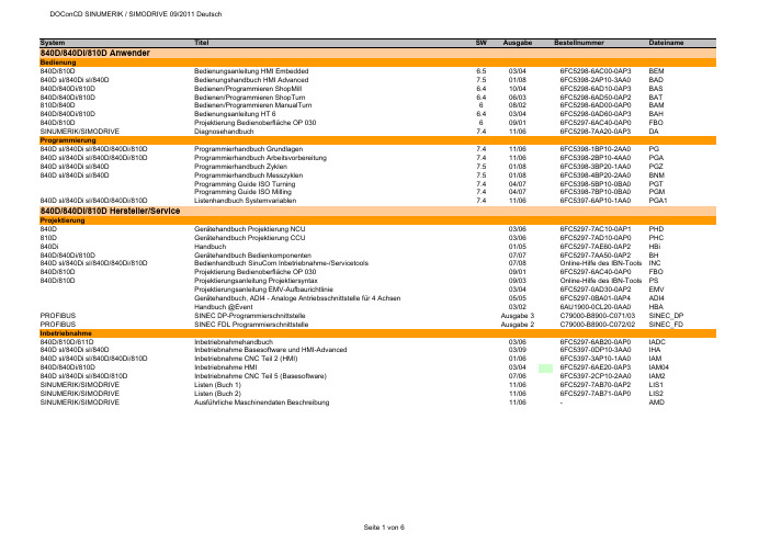
System Titel SW Ausgabe Bestellnummer Dateiname 840D/840Di/810D AnwenderBedienung840D/810D Bedienungsanleitung HMI Embedded 6.503/046FC5298-6AC00-0AP3BEM840D sl/840Di sl/840D Bedienungshandbuch HMI Advanced 7.501/086FC5398-2AP10-3AA0BAD840D/840Di/810D Bedienen/Programmieren ShopMill 6.410/046FC5298-6AD10-0AP3BAS840D/840Di/810D Bedienen/Programmieren ShopTurn 6.406/036FC5298-6AD50-0AP2BAT810D/840D Bedienen/Programmieren ManualTurn608/026FC5298-6AD00-0AP0BAM840D/840Di/810D Bedienungsanleitung HT 6 6.403/046FC5298-0AD60-0AP3BAH840D/810D Projektierung Bedienoberfläche OP 030609/016FC5297-6AC40-0AP0FBO SINUMERIK/SIMODRIVE Diagnosehandbuch7.411/066FC5298-7AA20-0AP3DA Programmierung840D sl/840Di sl/840D/840Di/810D Programmierhandbuch Grundlagen 7.411/066FC5398-1BP10-2AA0PG840D sl/840Di sl/840D/840Di/810D Programmierhandbuch Arbeitsvorbereitung 7.411/066FC5398-2BP10-4AA0PGA840D sl/840Di sl/840D Programmierhandbuch Zyklen 7.501/086FC5398-3BP20-1AA0PGZ840D sl/840Di sl/840D Programmierhandbuch Messzyklen7.501/086FC5398-4BP20-2AA0BNMProgramming Guide ISO Turning7.404/076FC5398-5BP10-0BA0PGTProgramming Guide ISO Milling7.404/076FC5398-7BP10-0BA0PGM840D sl/840Di sl/840D/840Di/810D Listenhandbuch Systemvariablen 7.411/066FC5397-6AP10-1AA0PGA1 840D/840Di/810D Hersteller/ServiceProjektierung840D Gerätehandbuch Projektierung NCU 03/066FC5297-7AC10-0AP1PHD810D Gerätehandbuch Projektierung CCU03/066FC5297-7AD10-0AP0PHC840Di Handbuch01/056FC5297-7AE60-0AP2HBi840D/840Di/810D Gerätehandbuch Bedienkomponenten07/076FC5297-7AA50-0AP2BH840D sl/840Di sl/840D/840Di/810D Bedienhandbuch SinuCom Inbetriebnahme-/Servicetools07/08Online-Hilfe des IBN-Tools INC840D/810D Projektierung Bedienoberfläche OP 03009/016FC5297-6AC40-0AP0FBO840D/810D Projektierungsanleitung Projektiersyntax09/03Online-Hilfe des IBN-Tools PSProjektierungsanleitung EMV-Aufbaurichtlinie03/046FC5297-0AD30-0AP2EMVGerätehandbuch, ADI4 - Analoge Antriebsschnittstelle für 4 Achsen05/056FC5297-0BA01-0AP4ADI4Handbuch @Event03/026AU1900-0CL20-0AA0HBA PROFIBUS SINEC DP-Programmierschnittstelle Ausgabe 3C79000-B8900-C071/03SINEC_DP PROFIBUS SINEC FDL Programmierschnittstelle Ausgabe 2C79000-B8900-C072/02SINEC_FD Inbetriebnahme840D/810D/611D Inbetriebnahmehandbuch03/066FC5297-6AB20-0AP0IADC840D sl/840Di sl/840D Inbetriebnahme Basesoftware und HMI-Advanced03/096FC5397-0DP10-3AA0IHA840D sl/840Di sl/840D/840Di/810D Inbetriebnahme CNC Teil 2 (HMI)01/066FC5397-3AP10-1AA0IAM840D/840Di/810D Inbetriebnahme HMI03/046FC5297-6AE20-0AP3IAM04840D sl/840Di sl/840D/810D Inbetriebnahme CNC Teil 5 (Basesoftware)07/066FC5397-2CP10-2AA0IAM2 SINUMERIK/SIMODRIVE Listen (Buch 1)11/066FC5297-7AB70-0AP2LIS1 SINUMERIK/SIMODRIVE Listen (Buch 2)11/066FC5297-7AB71-0AP0LIS2 SINUMERIK/SIMODRIVE Ausführliche Maschinendaten Beschreibung11/06-AMDFunktionen840D sl/840Di sl/840D/840Di/810D Funktionshandbuch Grundfunktionen11/066FC5397-0BP10-2AA0FB1840D sl/840Di sl/840D/840Di/810D Funktionshandbuch Erweiterungsfunktionen11/066FC5397-1BP10-2AA0FB2840D sl/840Di sl/840D/840Di/810D Funktionshandbuch Sonderfunktionen11/066FC5397-2BP10-2AA0FB3611D/840D/810D Funktionshandbuch Antriebsfunktionen05/106SN1197-0AA80-2AP1FBA840D/840Di/810D Funktionsbeschreibung Werkzeugverwaltung09/056FC5297-6AC60-0AP1FBW802D sl/840D/840D sl/840Di/840Di sl/810D Funktionshandbuch ISO-Dialekte für SINUMERIK03/076FC5297-7BP10-0AA0FBFA840D/611D Funktionshanduch HLA-Modul 03/066SN1197-0AB60-0AP4FBHLA840D/611D Funktionsbeschreibung ANA-MODUL02/006SN1197-0AB80-0AP0FBAN840D/611D Funktionsbeschreibung Safety Integrated03/066FC5297-7AB80-0AP1FBSI840D sl/840Di sl/840D/840Di/810D Funktionsbeschreibung Synchronaktionen11/066FC5397-5BP10-2AA0FBSY840D Funktionsbeschreibung Digitalisieren 07/996FC5297-4AC50-0AP0FBD840D/840Di/810D Funktionsbeschreibung Ferndiagnose03/046FC5297-0AF00-0AP3FBFE840D Funktionsbeschreibung C-PLC-Programmierung03/966FC5297-3AB60-0AP0FBP840D/840Di/810D Funktionsbeschreibung ShopMill 02/056FC5297-6AD80-0AP3FBSP840D/840Di/810D Funktionsbeschreibung ShopTurn03/046FC5297-6AD70-0AP2FBT840D/810D Funktionsbeschreibung ManualTurn08/026FC5297-6AD50-0AP0FBMA840D/810D Funktionsbeschreibung ManualTurn, Ergänzende Informationen07/04-FBMAx802D/802D base lineAnwender802D base line Bedienen und Programmieren, Drehen208/056FC5698-2AA00-1AP4802D_BPD802D Kurzanleitung Drehen111/006FC5698-1AA30-0AP0802DBNKD802D Kurzanleitung ISO-Dialekt Drehen109/016FC5698-1AA60-0AP0802D_ISD802D Bedienen und Programmieren, Fräsen208/056FC5698-2AA10-1AP5802D_BPF802D Kurzanleitung Fräsen111/006FC5298-1AA40-0AP0802DBNKF802D Kurzanleitung ISO-Dialekt Fräsen 109/016FC5698-1AA50-0AP0802D_ISF802D Diagnoseanleitung110/026FC5698-2AA20-0AP1802D_DIA Hersteller/Service802D base line Funktionsbeschreibung11/036FC5697-2AA10-0AP2802D_fb802D base line Inbetriebnahmehandbuch08/056FC5697-2AA00-1AP5802D_IBNGerätehandbuch, ADI4 - Analoge Antriebsschnittstelle für 4 Achsen05/056FC5297-0BA01-0AP4ADI4802S/802C base lineAnwender802S/ 802C base line Bedienen und Programmieren, Drehen408/036FC5598-4AA01-0AP0802SC_BPD 802S/ 802C base line Bedienen und Programmieren, Fräsen408/036FC5598-4AA11-0AP0802SC_BPF802S/ 802C base line Diagnoseanleitung408/036FC5598-4AA21-0AP0802SC_DIA Hersteller/Service802S/802C base line Funktionsbeschreibung08/036FC5597-4AA11-0AP0802SC_FB802C base line Inbetriebnahmeanleitung08/036FC5597-4AA21-0AP0802C_IBN802S base line Inbetriebnahmeanleitung08/036FC5597-4AA01-0AP0802S_IBN SIMODRIVE base line A Start-Up09/046SN1197-0AB21-0BP1802C_IBN_SBLASIMODRIVE611 digital Projektierungshandbuch Umrichter05/086SN1197-0AA00-1AP1PJU611 universal Funktionshandbuch06/116SN1197-0AB20-2AP3FBU611 universal Tausch Ersatzteil07/05A5E00150834FBU_TE611 universal Tausch Ersatzteil HR/HRS12/05A5E00423710FBU_TEH611 analog Inbetriebnahmeanleitung10/006SN1197-0AA60-0AP6IAA611 analog Beschreibung10/006SN1197-0AA30-0AP1BSFunktionsbeschreibung FM-STEPDRIVE/SIMOSTEP02/056SN1197-0AA70-0YP4FBSTSINAMICS S120/SIMODRIVE Systemhandbuch Schaltschrankintegration09/076SL3097-0AT00-0AP0SH1 SIMODRIVE SensorBenutzeranleitung Absolutwertgeber mit PROFIBUS-DP07/056SN1197-0AB10-0YP4BHAProjektierungshandbuch Hohlwellenmesssystem SIMAG H201/116SN1197-0AB31-0AP8PMH2Montageanleitung SIMAG H2 an SIMAG H08/05-SIMAGH2_M1Montageanleitung SIMAG H2 an SIZAG 208/05-SIMAGH2_M2Montageanleitung Zahnradgeber SIZAG 205/086SN1197-0AB00-0YP3SIZAG2_MBetriebsanleitung Gebersysteme ERN 1381.00106/03610.41 334.02ERN1381_BEBetriebsanleitung Gebersysteme ERN 1387 … / S21 / EQN 1325 …01/05610.41 304.02ERN1387_BEBeiblatt Anschlusshaube Hohlwellengeber PROFIBUS DP06/05-SSB_DPHBeiblatt Anschlusshaube Vollwellengeber PROFIBUS DP05/04-SSB_DPVBeiblatt Geberstecker SSI - EnDat06/08-SSB_SSIBeiblatt Geberstecker TTL - HTL- 1Vpp07/04-SSB_TTL Synchronmotoren1FK6Projektierungsanleitung Drehstrom-Servomotoren05/036SN1197-0AD05-0AP0PFK61FK7Projektierungshandbuch Synchromotoren10/056SN1197-0AD06-0AP1PFK71FK7Betriebsanleitung Drehstrom-Servomotoren 1FK7 02. - 1FK7 10. 03/11610.40700.01c1FK7_BE1FK7Betriebsanleitung Getriebemotoren03/05610.40 064.011FK7G_BE1FK7/1FT6Betriebsanleitung Getriebemotoren-Planetengetriebe09/05610.40 072.011FK7GP_BE1FT5Projektierungsanleitung Drehstrom-Servomotoren 05/036SN1197-0AD01-0AP0PFT51FT5Betriebsanleitung Drehstrom-Servomotoren 1FT5 02. -1FT5 04.09/93610.42078.21.a1FT502_BE1FT5Betriebsanleitung Drehstrom-Servomotoren 1FT5 06. -1FT5 13.04/93610.41199.21.c1FT506_BE1FT6Projektierungshandbuch Synchronmotoren 1FT610/056SN1197-0AD02-0AP1PFT61FT6Betriebsanleitung Drehstrom-Servomotoren 1FT6 02. -1FT6 10.07/03610.43 410.211FT602_BE1FT6Betriebsanleitung Drehstrom-Servomotoren 1FT6 13. -1FT6 16.03/07610.43 600.211FT613_BE1FT6Instandhaltungsanleitung Drehstrom-Servomotoren 1FT6 03 - 04 / 06 - 1307/96610.43411.02.a1FT6_IA1FT7Projektierungshandbuch Synchronmotoren 1FT703/106SN1197-0AC13-0AP3PFT71FT7Betriebsanleitung Synchronmotoren 1FT705/11610.40075.01c1FT7_BE1FE1Projektierungshandbuch Synchron-Einbaumotoren09/086SN1197-0AC00-1AP0PFE11FE1Montagehandbuch Synchron-Einbaumotoren10/10610.43000.011FE1_M1FE1Betriebsanleitung Spannungs-Begrenzungs-Modul VPM20008/09A5E00302261B1FE1_VPM200_BE 1FE1Betriebsanleitung Spannungs-Begrenzungs-Modul VPM200 DYNAMIK08/09A5E00777655A1FE1_VPM200D_BE 1FE1Betriebsanleitung Spannungs-Begrenzungs-Modul VPM12008/09A5E00302281B1FE1_VPM120_BE 1PH8Betriebsanleitung Synchron-/Asynchronmotoren 1PH813 und 1PH81605/10610.48006.011PH813_BE1PH8Betriebsanleitung/Montageanleitung Drehstrom-Synchronmotoren 1PH818, 1PH82207/10A5E03029571B AA1PH818S_BE1PH8Betriebsanleitung Drehstrom-Synchronmotoren 1PH818, 1PH82209/09A5E02446774B AB1PH818S_BE0909 2SP1Projektierungshandbuch ECS-Motorspindel11/086SN1197-0AD04-0AP5PMS2SP1Betriebsanleitung ECS-Motorspindel02/116SN1197-0AD14-0AP12SP1_BEAsynchronmotoren1PH2Projektierungsanleitung Asynchronmotoren 10/036SN1197-0AC63-0AP0APH21PH2Betriebsanleitung Drehstrom-Einbaumotoren 04/96610.43 414.021PH2_BE1PH4Projektierungshandbuch Asynchronmotoren04/066SN1197-0AC64-0AP1APH41PH4Betriebsanleitung Asynchronmotoren 1PH405/10610.43093.01e1PH4_BE1PH7Projektierungsanleitung Asynchronmotoren05/046SN1197-0AC65-0AP1APH71PH7Betriebsanleitung Fremdbelüftete Drehstrommotoren 1PH7 10-1611/08610.43 429.211PH7_BE1PH7Betriebsanleitung Drehstrom-Asynchronmotor 1PH71802/08A5E00215737A1PH718_BE 1PH7Betriebsanleitung Drehstrom-Asynchronmotor 1PH72203/08A5E00264361A1PH722_BE 1PH7Betriebsanleitung Drehstrom-Asynchronmotor 1PH72803/08A5E00171047A1PH728_BE 1PH8Betriebsanleitung Asynchronmotoren 1PH808 und 1PH81005/10610.48004.011PH808_BE 1PH8Betriebsanleitung Synchron-/Asynchronmotoren 1PH813 und 1PH81605/10610.48006.011PH813_BE 1PH8Betriebsanleitung Drehstrom-Asynchronmotor 1PH818, 1PH822, 1PH82807/09A5E02605207B AA1PH8_BE1PM6/1PM4Projektierungshandbuch Hohlwellenmotoren08/056SN1197-0AD03-0AP1PPM1PM6Betriebsanleitung Hohlwellenmotoren, luftgekühlt12/05610.40 037.311PM6_BE1PM4Betriebsanleitung Hohlwellenmotoren, flüssigkeitsgekühlt12/05610.40 036.311PM4_BE Linear-/Torquemotoren1FN1Projektierungshandbuch Linearmotoren10/066SN1197-0AB72-0AP0PFN11FN3Projektierungshandbuch Dauerlastmotoren03/086SN1197-0AB74-0AP2PFN3DLM1FN3Projektierungshandbuch Spitzenlastmotoren04/086SN1197-0AB73-0AP1PFN3SLM1FW6Projektierungshandbuch Einbau-Torquemotoren05/096SN1197-0AD00-0AP7PJTM1FW6Betriebsanleitung Einbau-Torquemotoren 1FW606/116SN1197-0AF00-0AP01FW6_BE1FN1/1FN3/1FW6Gerätehandbuch Sensor Module External SME9x11/076SN1197-0AE10-0AP0GH_SME9x Sicherheitshinweise für Direktantriebe01/10-1FN_FW_SH Dezentrale AntriebstechnikPOSMO A Benutzerhandbuch10/076SN2197-0AA00-1AP1POS1 POSMO A Betriebsanleitung Power Management Modul DC-PMM / 24 V04/03-POS1_BE24 POSMO A Betriebsanleitung Power Management Modul DC-PMM / 48 V04/03-POS1_BE48 POSMO A Montageanleitung08/03A5E00158596POS2 POSMO A Montageanleitung "getrennte Variante"12/06A5E00397126Aaf posa_mv POSMO A Montageanleitung Tausch Antriebseinheit 12/01A5E00101611B posa_mta POSMO A/SI Montageanleitung Tausch Getriebe02/04A5E00297127posa_mtg POSMO SI/CD/CA Benutzerhandbuch06/086SN2197-0AA20-1AP4POS3 POSMO SI/CD/CA Montageanleitung Entstörfilter 08/03A5E00245073B-A1poscd_mf POSMO SI/CD/CA Montageanleitung Tausch PROFIBUS–Einheit 07/06A5E00145169 ae poscd_mpe POSMO SI/CD/CA Montage Entstörfilter ECOFAST03/03-poscd_mfe POSMO SI/CD/CA Montageanleitung Tausch PROFIBUS-Einheit ECOFAST07/06A5E00335711 ac poscd_mpee POSMO SI Montageanleitung07/06A5E00282739 ac poss_m POSMO SI Montageanleitung Tausch Lüfter 07/05462 028 0042 00ab poss_mtl POSMO SI Montageanleitung Tausch Antriebseinheit 07/05A5E00145904ac poss_mta POSMO SI Montageanleitung mit PROFIBUS–Einheit ECOFAST07/06A5E00335557 ac poss_mpe POSMO CD/CA Montageanleitung07/06A5E00257954 ad posca_m POSMO CD/CA Montageanleitung mit PROFIBUS–Einheit ECOFAST07/06A5E00335554 ac posca_meMotion Control Information System840D sl/840Di sl/840D/840Di/810D Funktionshandbuch Rechnerkopplung RPC SINUMERIK10/056FC5297-6AD61-0AP1FBR840D sl/840Di sl/840D/840Di/810D Funktionshandbuch NC-Programmmanagement DNC Plant/Cell12/106FC5297-2AE80-0AP3FBDN840D sl/840Di sl/840D/840Di/810D Funktionsbeschreibung NC-Programmmanagement DNC Machine09/036FC5297-1AE81-0AP0FBDM840D sl/840Di sl/840D/840Di/810D Benutzeranleitung Bedienoberfläche "DNC-Machine"07/07-BBDNC 840D sl/840Di sl/840D/840Di/810D Funktionsbeschreibung,Vorbeugende Instandhaltung TPM02/076FC5260-2FX28-0AG3FBTP840D sl/840Di sl/840D/840Di/810D Funktionsbeschreibung TDI Ident Connection06/036FC5297-1AE60-0AP0FBIC840D sl/840Di sl/840D/840Di/810D Bedienungsanleitung Tool Data Information (TDI) 06/076FC5297-6AE01-0AP4BTDI840D sl/840Di sl/840D/840Di/810D Betriebsanleitung ADDM Server Version 6.008/05-BEDMS 840D sl/840Di sl/840D/840Di/810D Betriebsanleitung ADDM Client Version 6.110/07-BEDMC 840D sl/840Di sl/840D/840Di/810D Betriebsanleitung ADDM Agent Version 1.107/05-BEDMA 840D sl/840Di sl/840D/840Di/810D Benutzeranleitung MDA / PDA Maschinenauswertungen08/07-GUIRT 840D sl/840Di sl/840D/840Di/810D Benutzeranleitung MDA Monitor08/07-MonGUI 840D sl/840Di sl/840D/840Di/810D Benutzeranleitung MDA Bedienoberfläche "Projektierung"08/07-PrjGUI840D sl/840Di sl/840D/840Di/810D Benutzeranleitung MDA Werkskalender08/07-WkalGUI 840D sl/840Di sl/840D/840Di/810D Projektierung MDA10/07-PMDA840D sl/840Di sl/840D/840Di/810D Inbetriebnahme MDA Machine10/07-IMDA_M 840D sl/840Di sl/840D/840Di/810D Inbetriebnahme MDA Cell10/07-IMDA_C 840D sl/840Di sl/840D/840Di/810D Inbetriebnahme MDA HMI06/07-IMDA_HMI 840D sl/840Di sl/840D/840Di/810D Inbetriebnahme Datenbankprogramm Oracle für MDA04/05-IMDA_O 840D sl/840Di sl/840D/840Di/810D Funktionsbeschreibung MDA Machine 10/03-FMDA SIMATIC PostionierbaugruppenHandbuch FM 353 für Schrittantrieb08/086ES7353-1AH01-8AG0FM353Handbuch FM 354 für Servoantrieb08/086ES7354-1AH01-8AG0FM354Getting Started Erste Schritte zur Inbetriebnahme FM 354/FM 35304/07-FM354_GSHandbuch FM 357-2 für Servo- bzw. Schrittantrieb01/036ES7357-4AH00-8AG0FM357_2Handbuch FM 453 für Servo- bzw. Schrittantrieb08/086ES7453-3AH00-8AG0FM453Getting Started Erste Schritte zur Inbetriebnahme FM 45304/07-FM453_GS ePS Network Services840D/840Di/810D Installationshandbuch02/08-EPS_IA 840D/840Di/810D Bedienhandbuch11/06-EPS_BH 840D sl/840Di sl/840D/840Di Projektierungshandbuch04/10-EPS_PH 840D sl/840Di sl/840D/840Di Funktionshandbuch12/10-EPS_FH 840D sl/840D Betriebsanleitung eP-Satellite Server12/10-EP_BA 840D/840Di/810D Leistungsbeschreibung ASP Schein01/09-EPS_LB 840D sl/840Di sl/840D/840Di Release Notes12/10-EPS_RNSIMATICSIMATIC S7Getting Started: Erste Schritte und Übungen mit STEP 7 V5.403/06-S7_GS SIMATIC S7Programmieren mit STEP 7 V5.403/06-S7P SIMATIC S7HW konfigurieren und Verbindungen projektieren mit STEP 7 V5.403/06-S7_HW SIMATIC S7-300/400Referenzhandbuch Kontaktplan (KOP)03/06-S7_KOP SIMATIC S7-300/400Referenzhandbuch Funktionsplan (FUP)03/06-S7_FUP SIMATIC S7-300/400Referenzhandbuch Anweisungsliste (AWL)03/06-S7_AWL SIMATIC S7-300/400Referenzhandbuch System- und Standardfunktionen03/06-S7_SFC SIMATIC S7-300Betriebsanleitung CPU 31xC und CPU 31x: Aufbauen06/08-S7_BA31A SIMATIC S7-300Gerätehandbuch CPU 31xC und CPU 31x, Technische Daten06/08-S7_GH31TD SIMATIC S7-300Referenzhandbuch CPU-Daten CPUs 312 IFM bis 318-2 DP10.01-S7300Re2 SIMATIC S7-300Operationsliste CPU Daten: CPUs 312 IFM bis 318-2 DP10.01-S7OP1 SIMATIC S7-300Operationsliste CPU 31xC, CPU 31x06/08-S7OP2 SIMATIC S7-300Technologische Funktionen: CPU 31xC02/07-S7300TF SIMATIC S7-200Systemhandbuch09/07-S7200SH SIMATIC S7-200Systemhandbuch CPU 210Ausgabe 1-S7_C210 SIMATIC Systemhandbuch Kommunikation mit SIMATIC09/06-SSH_Komm SIMATIC HMI Betriebsanleitung Bediengerät Mobile Panel 177 (WinCC flexible)07/05-SBE_MP177 Info/TrainingSystemhandbuch Safety Integrated20056ZB5000-0AA02-0BA1APPL_HBSystemhandbuch Safety Integrated Nachtrag20066ZB5000-0AB01-0BA0APPL_HBNTrainingsunterlage Einfacher fräsen mit ShopMill08/066FC5095-0AA50-0AP2TUSMTrainingsunterlage Einfacher drehen mit ShopTurn04/046FC5095-0AA80-0AP1ST_ein840D/840Di/810D Einsteigeranleitung Fräsen und Drehen 10/036FC5095-0AB00-0AP1SIN_ein840D/840D sl/840Di Handbuch 5 Achs-Bearbeitung05/096FC5095-0AB10-0AP1SIN_WF5 840D/840Di/810D/802D sl Handbuch Werkzeug- und Formenbau (3 Achsen)08/076FC5095-0AB20-0AP0SIN_WF3 SteuerungsübersichtSINUMERIK powerline Funktionsübersichten 2009-BU840D/810D Steuerungsübersicht Fräsen mit ShopMill06/07-SSM840D/810D Steuerungsübersicht Drehen mit ShopTurn04/07-SSTaktualisierte Ausgabeerstmalig auf DOConCD。
i-PAC 10-1Xtratec® – Heptagon milling cutter F4045Table of contentF404501 02 03 04 05 06Product description Results from the market Product range Applications & Target groups Advantages and customers benefits Setting instruction2| April 2010 | VM | Spiegelhalder01 – Product description 产品描述General points 概述Wedge clamping 楔块锁紧DC = 63 – 200 mm DC = 80 – 200 mmNickelized surface 表面镀镍3| April 2010 | VM | Spiegelhalder01 – Product description 产品描述Basic body 刀体• Heptagon Face Milling Cutter, Kappa 45° 七边形面铣刀 Ø 63 (80) - 200 mm apmax = 4 / 6 mm Insert with negative basic shape 负型刀片 14 cutting edges per inserts 14 刃/片 片 Two insert sizes for complete program 2 种刀片尺寸 close pitch for cast iron machining 密齿设计, 密齿设计 适用于铸铁加工• • • • • •4| April 2010 | VM | Spiegelhalder01 – Product description 产品描述Basic body 刀体• wedge clamping of the insert 楔块锁紧– quick insert change 快速更换刀片 – stable insert 装夹稳定• Torx Plus screw– Improved Handling 操作简便 – Higher clamping / unclamping torque 锁紧/松开安全可靠• Hard nickelized surface 表面镀镍处理– Protection against wear and corrosion 抗磨损, 防腐蚀 – Improved chip removal 排屑流畅5| April 2010 | VM | Spiegelhalder01 – Product description 产品描述Insert clamping 刀片锁紧 刀片锁紧6| April 2010 | VM | Spiegelhalder01 – Product description 产品描述Insert clamping 刀片松开 刀片松开7| April 2010 | VM | Spiegelhalder01 – Product description 产品描述The insert 刀片Design DesignInsert tolerance 刀片公差Geometry Index 槽型代码negative basic shap 负型刀片8| April 2010 | VM | Spiegelhalder01 – Product description 产品描述The insert 刀片„PVD hole“• •negative basic shape 负型刀片 Heptagon basic shape with 14 cutting edges 七边形刀片, 14刃 七边形刀片 刃 designation 型号 XNHF.. Insert completely ground (Circumference) 周边磨削刀片 With corner radius 圆角刀片– XNHF070508-… XNHF090612-…• •• •With secondary cutting edge 副切削刃刀片– XNHF0705ANN- … (1,1 mm) XNHF0906ANN-… (1,4 mm)9| April 2010 | VM | Spiegelhalder01 – Product description 产品描述The insert 刀片XNHF0705ANN-D…XNHF070508-D…10| April 2010 | VM | Spiegelhalder01 –Product description产品描述Insert geometries刀片槽型•D27 The stable one稳定型–for unfavourable machining conditions适用于不理想工况–maximum cutting edge stability切削刃最稳定–high feed rates高进给–10°rake angle前角•D57 The universal one通用型–for medium machining conditions用于中等工况–universal application for most materials适用多数工件材料–10°rake angle前角•D67 The easy cutting one轻快型–for good machining conditions用于良好工况–low cutting forces切削抗力小–medium feed rates中等进给–10°rake angle前角Machining example加工案例F4045.B40.160.Z20.06Work pieces工件Periphery•Work piece工件–12,8 Liter and 14,8 Liter Diesel motor blocks12.8升和14.8升柴油机缸体•Material材料–EN-GJV-400 (GGV400)cast iron with vermiculargraphite蠕墨铸铁•Machine机床–Heller MCH 400DActual situation现状•Tool刀体–F4033.B.160.Z20.06•Insert刀片–SNGX1205ANN-F27 WKP25•Parameter参数–a p= 3-4 mm–v c= 185 m/min–f z= 0,36 mm–v f= 2650 mm/min•Tool life刀具寿命–56 Components工件•Remarks备注–Machining of the head deck– 2 passes走刀–dry干铣WALTER solution•Tool刀体–F4045.B40.160.Z20.06•Insert刀片–XNHF090616-D27 WKP25•Parameter参数–a p= 8 mm–v c= 200 m/min–f z= 0,25 mm–vf = 1990 mm/min•Tool life刀具寿命–90 components工件•Remarks备注– 1 pass走刀–Saved 84 seconds in cycle time per component每个零件节省84 秒Result 结果•Machining costs 加工成本–-44%–Saving 节省–108.891$ ≈80.726€•Tool life 刀具寿命–+ 60%–From 56 to 90 components 从56 件提高到90 件153045607590F4045F4033T o o l l i f e [p i e c e s]03 –Program range bodies刀体产品系列03 –Program range inserts刀片产品系列04 -Application areas& Target groups应用领域•For all cast materials所有铸铁材料加工•Applications应用–Face milling, roughing平面铣削, 粗加工–Mass production大批量生产–Transfer line专机线–stable machining center稳定的加工中心•Main target groups主要行业–General mechanical engineering通用机械行业–Automobile industry and its suppliers汽车行业及其零部件供应商–Energy industry能源行业04 -Application areas & Target groups 应用领域Overview grades for the machining of cast iron 铸铁加工材质综述ToughnessW e a r r e s i s t a n c e05 –Benefits for the customer客户获益•Low cutting tool costs降低刀具成本–Due to fourteen cutting edges per insert由于每个刀片有14 刃•High chip removal volume提高材料去除率–even on low-powered machines即使在低功率机床上–Low power consumption due to the high-positive geometry大前角槽型降低功率消耗–high feed rate due to close pitch version密齿设计提高进给•High process reliability提高工艺可靠性–Due to stable indexable inserts (negative basic shape)负型刀片, 加工稳定–large support of insert on the body刀体上的刀片支撑面大Xtra tec Heptagon milling cutter F4045 Setting instruction安装指南06 –Setting instruction F4045安装指南•Required parts要求部件:–Torx screwdriver Torx 螺丝刀–Spanner扳手–Inserts刀片–F4045 milling cutter, including thescrews and wedges刀体, 包括螺钉和楔块Bonding agent (not fat) 06 –Setting instruction F4045安装指南•Step 1:–Slide the wedge, as shown in the picture on the screwdriver. Place the sum screw on the tip of the screwdriver.先将楔块放入扳手, 并将放上螺钉, 注意方向.•Step 2:–Screw the wedge and the sum screw in the thread. Use the spanner to hold the wedge in position.将楔块和螺钉旋入刀体, 用固定扳手将楔块定位–XNHF0705.. : SW8–XNHF0906.. : SW1006 –Setting instruction F4045安装指南•Step 3:–Once the wedge is screwed in farenough to place him like shown in thepicture on the right.确保楔块旋入足够长度, 将其按照右图所示放置.•Step 4:–Now you can insert the insert into yourset position. Hold the insert firmly whiletightening the sum screw. The wedge ismoving in the right position as soon asyou start to bolt and clamps the insertin the correct position.现在可以将刀片放入刀片槽. 推紧刀片, 旋入螺钉. 当你开始在正确位置锁紧刀片的时候,楔块也将自动旋转到正确的位置.06 –Competitors竞争对手ISCAR F45WG/NM•Kappa 44,3°•two different pitches•one insert size•Octagon negative•16 cutting edges •designation ON.U080608..•Ic= 20,2 mm•ap = 5,5 mm06 –Competitors竞争对手Coromant CoroMill365•Kappa 65°(30°)•two different pitches•one insert size•square negative•8 cutting edges•designation R365-1505ZNE..•Ic= 15 mm•ap = 4,5 (6,1) mm06 –Competitors竞争对手Kennametal Hexacut •Kappa 45°(60°)•one pitch•one insert size•Hexagon negative•12 cutting edges •designation HN.X0905…•Ic= 15,88 mm•ap = 6,5 (8) mm •secondary c. e. 1,3 mm06 –Competitors竞争对手Kennametal Dodeka•Kappa 45°•one pitch•one insert size•hexagon negative•12 cutting edges •designation HNGJ0905AN…•Ic= 15,88 mm•ap = 4,5 mm•secondary c.e. 1,8 mm06 – Competitors 竞争对手 Mitsubishi AHX• • • • • • • • • Kappa 40° two pitches one insert size Heptagon negative 14 cutting edges designation NNMU200608.. Ic = 20 mm ap = 6 mm secondary c.e. 1 mm31| April 2010 | VM | Spiegelhalder07 - Typical work pieces 典型零件Cylinderhead 缸盖Rotor hub 轮毂Manifolt 排气管Engin block 缸体32| April 2010 | VM | Spiegelhalder07 - Typical work pieces 典型零件Differential case 箱体Differential case 箱体Inlet 进气管33| April 2010 | VM | SpiegelhalderThank you.。