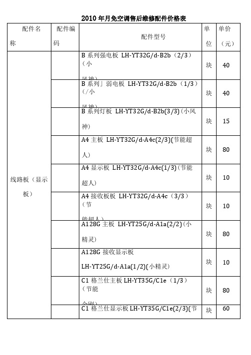
EX245-SPR2-X35_EN_060125
- 格式:pdf
- 大小:1.08 MB
- 文档页数:56


伟肯变频器用户手册安装和运行前,请务必遵照如下的起动和运行快速指南操作,并依次完成其中11个操作步骤。
如有任何问题,请与当地经销商联系。
快速指南1. 检查产品是否与定单相符,见第3章。
2. 进行任何调试前,请仔细阅读第1章中的安全规程。
3. 进行机械安装前,请根据第5章的说明检查外部环境条件和变频器周边的最小间距。
4. 按第6章的说明检查电机电缆、主电源电缆、主电源熔断器的规格和电缆的连接情况。
5. 根据第5章中的安装说明进行安装。
6. 根据§6.1.1中的说明检查控制电缆规格及接地系统。
7. 根据第7章中的说明使用控制面板。
8. 所有的参数都有工厂设定的缺省值。
为了确保正确运行,请检查下列电机铭牌数据和参数组P2.1中相应的参数设置。
见§8.3.2。
• 电机额定电压P2.1.6• 电机额定频率P2.1.7• 电机额定转速P2.1.8• 电机额定电流P2.1.9• 电机功率因数P2.1.10所有的参数说明见多目标控制应用手册。
9. 阅读第8章,按照调试步骤进行操作。
10. 至此,可以开始使用Vacon NXL变频器了。
11. 在本手册的结尾,您会看到有关默认I/O,控制面板菜单,监控值,故障代码和基本参数的快速帮助。
违反上述操作步骤所造成的任何损失,Vacon Plc概不负责。
目录VACON NXL用户手册目录1 安全指导2 EU认证3 收货4 技术数据5 安装6 电缆和接线7 控制面板8 调试9 故障跟踪10 选件卡OPT-AA的描述11 选件卡OPT-AI的描述VACON NXL多目标控制应用手册vacon • 3Vacon China电话: +86-10-51280006 传真: +86-10-65813733 24小时支持热线: +86-137******** Email :***************.cn关于VACON NXL 用户手册和多目标控制应用手册恭喜您选择了Vacon NXL 变频器所提供的平滑控制!用户手册将为您提供有关Vacon NXL 变频器的安装,调试和操作的必要信息。

en55024标准名称
EN 55024是欧洲电子设备用电磁兼容性标准的一个重要名称。
它规定了电子设备在电磁环境中的性能要求,以确保设备在遇到电磁干扰时能正常工作,同时不会对其它设备产生干扰。
EN 55024标准适用于各种类型的电子设备,包括计算机、通信设备、家用电器、工业设备等。
根据这一标准,电子设备应具备抵抗电磁场干扰、抵抗电静电放电、抵抗快速瞬变干扰等能力。
根据EN 55024标准的要求,电子设备应该通过各种测试,以验证其在特定的电磁环境中的表现。
这些测试包括:
1. 抗传导干扰测试:验证设备是否能够抵抗来自电源线和信号线的传导干扰;
2. 抗辐射干扰测试:验证设备是否能够抵抗来自电磁场中的辐射干扰;
3. 静电放电测试:验证设备是否能够抵抗来自静电放电的干扰;
4. 快速瞬变测试:验证设备是否能够抵抗来自突然的电压和电流变化引起的干扰。
通过遵循EN 55024标准,设备制造商可以确保其产品在电磁环境中能够正常运行,并且不会对其他设备造成干扰。
这对于确保电子设备的可靠性和互通性至关重要。
总结起来,EN 55024标准为电子设备的电磁兼容性提供了统一的要求和测试方法,以确保设备在电磁环境中的稳定性和可靠性。
制造商和用户都应该密切遵守这一标准,以确保设备在使用过程中不会受到电磁干扰的影响。


How to OrderOptionOptionPiping direction Part no.Bracket Panel mountPanel mount + Front protection coverRear portedRear portedBottom ported Rear portedBottom ported Rear portedBottom portedZS-24-A ZS-24-D ZS-35-A ZS-35-C ZS-35-B ZS-35-F ZS-35-EFor vacuum/compound pressureFor positive pressure 80ISE 02N 80ZSE 02N –0.1 to 1 MPa –0.1 to 2 MPaRated pressure range8080H 0 to –101 kPa –100 to 100 kPaRated pressure range8080FNPN open collector 1 output PNP open collector 1 output NPN open collector 2 outputs PNP open collector 2 outputsNPN open collector 2 outputs + Analog voltage output/Auto-shift switching PNP open collector 2 outputs + Analog voltage output/Auto-shift switching NPN open collector 2 outputs + Analog current output/Auto-shift switching PNP open collector 2 outputs + Analog current output/Auto-shift switchingInput/OutputN P A B R T S VNote) Fixed unit ISE80H: MPaOthers : MPa, kPaWith unit display switching function Fixed SI unit Note)Initial value psiOption 1NilMPOption 3Note) All texts in both English and JapaneseOperating Note)manual b (Booklet)—b (CD-ROM)Calibration certificate ———Nil Symbol YWb (Booklet)—b (CD-ROM)Calibrationcertificateb b b Symbol K T R PipingR1/4(M5 female threaded)Rear portedBottom portedNPT1/4(M5 female threaded)G1/4(M5 female threaded)Rc1/8URJ1/4TSJ1/402N02F02R1/4(M5 female threaded)NPT1/4(M5 female threaded)Rc1/8URJ1/4TSJ1/402LN02L C01A2B2C01L A2L B2LNoneWith bracketRear portedBottom portedBottom portedOption 2NilABPanel mountWith bracket Note)Rear portedBottom portedPanel mount + Front protection coverRear portedCDNote) Rear ported onlyTable 1Made to OrderNote) Not applicable to the rated pressure range 0 to 2MPa specification. Refer to page 743 for detail.Wetted parts: Stainless steel 316L Lead wire length 3 m Restrictor installed fittingSymbolSpecifications-X500 Note)-X501-X510ZS-24-AZS-35-AZS-24-DZS-35-CZS-35-BZS-35-FZS-35-EM MMade to OrderRefer to Table 1 below.Operating Note)manual ®2-Color Display Digital Pressure Switch For General FluidsSeries ZSE80/ISE80732。


EN60335标准一览表BS EN 60335-2-27-1997家用电器和类似用途电器的安全规范.特殊要求.暴露于紫外线和红外辐射的皮肤Specification for safety of household and similar electrical appliances - Particular requirements - Skin exposure to ultraviolet and infrared radiationBS EN 60335-2-28-1996家用和类似电器的安全.电动缝纫机的特殊要求Specification for safety of household and similar electrical appliances - Particular requirements - Particular requirements for sewing machinesBS EN 60335-2-29-1997家用和类似用电气设备的安全规范.特殊要求.蓄电池充电器Specification for safety of household and similar electrical appliances - Particular requirements - Battery chargersBS EN 60335-2-30-1997家用和类似用途电器的安全规范.房间加热器的特殊要求Specification for safety of household and similar electrical appliances - Particular requirements - Room heatersBS EN 60335-2-31-1997家用和类似用途电器的安全规范.炉罩的特殊要求Specification for safety of household and similar electrical appliances - Particular requirements - Range hoodsBS EN 60335-2-32-1996家用和类似用途电器安全规范.特殊要求.按摩器Specification for safety of household and similar electrical appliances - Particular requirements for massage appliancesBS EN 60335-2-33-1992家用和类似用途电器安全规范.第2部分:特殊要求.第33节:咖啡碾和咖啡磨碎器Specification for safety of household and similar electrical appliances - Particular requirements - Coffee mills and coffee grindersBS EN 60335-2-34-2000家用和类似用途电器的安全规范.特殊要求.电机压缩机的特殊要求Specification for safety of household and similar electrical appliances - Particular requirements - Particular requirements for motor-compressorsBS EN 60335-2-35-1998家用和类似用途电器的安全规范.瞬时水加热器的特殊要求Specification for safety of household and similar electrical appliances - Particular requirements for instantaneous water heatersBS EN 60335-2-36-2000家用和类似用途电气设备的安全规范.特殊要求.商用电烹调炉灶、烘箱、炉架及炉架元件的特殊要求Specification for safety of household and similar electrical appliances - Particular requirements - Particular requirements for commercial electric cooking ranges, ovens, hobs and hob elementsBS EN 60335-2-37-2000家用和类似用途电气设备的安全规范.特殊要求.商用电深油煎锅的特殊要求Specification for safety of household and similar electrical appliances - Particular requirements - Particular requirements for commercial electric deep fat fryersBS EN 60335-2-38-2000家用和类似用途电气设备的安全规范.特殊要求.商用电平煎锅及其烤架的特殊要求Specification for safety of household and similar electrical appliances - Particular requirements - Particular requirements for commercial electric griddles and griddle grillsBS EN 60335-2-39-2000家用和类似用途电气设备的安全规范.商用多用途电平锅的特殊要求Specification for safety of household and similar electrical appliances - Particular requirements for commercial electric multi-purpose cooking pansBS EN 60335-2-40-1998家用电器和类似用途电器的安全规范.特殊要求.电加热泵,空气调节器和减湿器Specification for safety of household and similar electrical appliances - Particular requirements - Electrical heat pumps, air-conditioners and dehumidifiersBS EN 60335-2-41-1996家用和类似用途电气设备的安全规范.温度不超过35℃的液体泵的特殊要求Specification for safety of household and similar electrical appliances - Particular requirements - Pumps for liquids having a temperature not exceeding 35 ?BS EN 60335-2-42-2000家用和类似用途电气设备的安全规范.特殊要求.商用强制对流电炉、蒸汽锅和蒸汽对流烘炉的特殊要求Specification for safety of household and similar electrical appliances - Particular requirements - Particular requirements for commercial electric forced convection ovens, steam cookers and steam-convection ovensBS EN 60335-2-43-1997家用和类似电器的安全规格.衣服烘干器和毛巾架的特殊要求Specification for safety of household and similar electrical appliances - Particular requirements - Clothes dryers and towel railsBS EN 60335-2-44-1998家用电器和类似用途电器的安全规范.特殊要求.电熨斗Specification for safety of household and similar electrical appliances - Particular requirements - IronersBS EN 60335-2-45-1997家用和类似用途电器的安全规范.便携式电热器和类似用途器具的特殊要求Specification for safety of household and similar electrical appliances - Particular requirements - Portable heating tools and similar appliancesBS EN 60335-2-47-2000家用和类似用途电气设备的安全规范.特殊要求.商用电蒸煮锅的特殊要求Specification for safety of household and similar electrical appliances - Particular requirements - Particular requirements for commercial electric boiling pansBS EN 60335-2-48-2000家用和类似用途电气设备的安全规范.特殊要求.商用电烤架和电烤箱的特殊要求Specification for safety of household and similar electrical appliances - Particular requirements - Particular requirements for commercial electric grillers and toastersBS EN 60335-2-49-2000家用和类似用途电气设备的安全规范.特殊要求.商用电加热柜的特殊要求Specification for safety of household and similar electrical app liances - Particular requirements - Particular requirements for commercial electric hot cupboardsBS EN 60335-2-50-2000家用和类似用途电气设备的安全规范.特殊要求.商用电隔水炖锅的特殊要求Specification for safety of household and similar electrical appliances - Particular requirements - Particular requirements for commercial electric bains-marieBS EN 60335-2-51-1997家用和类似用途电气设备的安全规范.特殊要求.加热和供水装置用固定循环泵Specification for safety of household and similar electrical appliances - Particular requirements - Stationary circulation pumps for heating and service water installationsBS EN 60335-2-52-1996家用和类似电器的安全.特殊要求.口腔卫生用具的特殊要求Specification for safety of household and similar electrical appliances - Particular requirements - Particular requirements for oral hygiene appliancesBS EN 60335-2-53-1997家用和类似用途电气设备的安全规范.特殊要求.桑拿浴加热装置Specification for safety of household and similar electrical appliances - Particular requirements - Sauna heating appliancesBS EN 60335-2-54-1997家用和类似用途电气器具的安全规格.用液体的表面清洁器的特殊要求Specification for safety of household and similar electrical appliances - Particular requirements - Surface-cleaning appliances employing liquidsBS EN 60335-2-55-1997家用及类似用途电气设备的安全规范. 养鱼池和花园池塘用电气设备的特殊要求Specification for safety of household and similar electrical appliances - Particular requirements - Electrical appliances for use with aquariums and garden pondsBS EN 60335-2-56-1997家用和类似用途电器的安全规格.特殊要求.放映机和类似设备Specification for safety of household and similar electrical appliances - Particular requirements - Projectors and similar appliancesBS EN 60335-2-58-1997家用和类似用途电气器具的安全规格.商业电子洗碗机的特殊要求Specification for safety of household and similar electrical appliances - Particular requirements - Commercial electric dishwashing machinesBS EN 60335-2-59-1998家用电器和类似电器的安全规范.特殊要求.杀虫器Specification for safety of household and similar electrical appliances - Particular requirements - Insect killersBS EN 60335-2-60-1998家用和类似用途电气设备的安全规范.特殊要求.涡流浴池Specification for safety of household and similar electrical appliances - Particular requirements - Whirlpool bathsBS EN 60335-2-61-1996家用和类似电器的安全规范.蓄热式房间加热器的特殊要求Specification for safety of household and similar electrical appliances - Particular requirements - Thermal storage room heatersBS EN 60335-2-62-1997家用和类似电器的安全规范.特殊要求.商用电冲洗池Specification for safety of household and similar electrical appliances - Particular requirements - Commercial electric rinsing sinksBS EN 60335-2-63-1993家用和类似用途电器的安全.商业用电动烧水锅炉和液体加热器的特殊要求Specification for safety of household and similar electrical appliances - Particular requirements - Commercial electric water boilers and liquid heatersBS EN 60335-2-64-2000家用及类似用途电气设备的安全规范.特殊要求.厨房商用电机的特殊要求Specification for safety of household and similar electrical appliances - Particular requirements - Commercial electric kitchen machinesBS EN 60335-2-65-1996家用和类似电器的安全.第2部分第65节:空气清洁器的特殊要求Specification for safety of household and similar electrical appliances - Particular requirements - Air-cleaning appliancesBS EN 60335-2-66-1996家用和类似用途电器的安全.特殊要求.水床加热器Specification for safety of household and similar electrical appliances - Particular requirements - Water-bed heatersBS EN 60335-2-67-1999家用和类似用途电气设备的安全规范.特殊要求.工业和商业用途的地板处理机和地板清洗机的特殊要求Specification for safety of household and similar electrical appliances - Particular requirements - Particular requirements for floor treatment and floor cleaning machines, for industrial and commercial useBS EN 60335-2-68-1999家用和类似用途电气设备的安全规范.特殊要求.工业和商业用喷雾吸出式装置的特殊要求Specification for safety of household and similar electrical appliances - Particular requirements - Particular requirements for spray extraction appliances, for industrial and commercial useDIN EN 60335-2-69-2001家用和类似电气装置的安全.第2-69部分:工业和商业用的干和湿真空清洁器包括动力刷的特殊要求Safety of household and similar electrical appliances - Part 2-69: Particular requirements for wet and dry vacuum cleaners, including power brush, for industrial and commercial use (IEC 60335-2-69:1997, modified + A1:2000); German version EN 60335-2-69:1DIN EN 60335-2-70-1997家用及类似用途电器的安全.第2部分:挤奶机的特殊要求Safety of household and similar electrical appliances - Part 2: Particular requirements for milking machines (IEC 60335-2-70:1993); German version EN 60335-2-70:1996DIN EN 60335-2-71-1997家用及类似用途电器的安全.第2部分:繁殖和饲养动物用的电子加热器的特殊要求Safety of household and similar electrical appliances - Part 2: Particular requirements for electrical heating appliances for breeding and rearing of animals (IEC 60335-2-71:1993, modified); German version EN 60335-2-71:1995DIN EN 60335-2-72-2001家用和类似用途电器的安全.第2-72部分:工业和商业地板处理用自动机械的特殊要求Safety of household and similar electrical appliances - Part 2-72: Particular requirements for automatic machines for floor treatment for commercial and industrial use (IEC 60335-2-72:1995, modified + A1:2000); German version EN 60335-2-72:1998 + A1:2000DIN EN 60335-2-73-1997家用及类似用途电器的安全.第2部分:固定浸入式加热器的特殊要求Safety of household and similar electrical appliances - Part 2: Particular requirements for fixed immersion heaters (IEC 60335-2-73:1994, modified); German version EN 60335-2-73:1996DIN EN 60335-2-74-1997家用及类似用途电器的安全.第2部分:便携浸入式加热器的特殊要求Safety of household and similar electrical appliances - Part 2: Particular requirements for portable immersion heaters (IEC 60335-2-74:1994); German version EN 60335-2-74:1996DIN EN 60335-2-75-1997家用和类似用途电器的安全第2-75部分:商用售卖机的特殊要求DIN EN 60335-2-76-2002家用和类似用途电器的安全性.第2-76部分:电牧栏增能器的特殊要求Safety of household and similar electrical appliances - Part 2: Particular requirements for electric fence energizers (IEC 60335-2-76:1997, modified + A1:1999) German version EN 60335-2-76:1999 + A1:2001DIN EN 60335-2-77-2001家用和类似用途电气设备的安全.第2-77部分:非专业人员操纵的交流电源剪草机的特殊要求Safety of household and similar electrical appliances - Part 2-77: Particular requirements for pedestrian controlled mains-operated lawnmowers (IEC 60335-2-77:1996, modified); German version EN 60335-2-77:2000BS EN 60335-2-78-1997家用和类似电器的安全规格.户外烤肉架的特殊要求Specification for safety of household and similar electrical appliances - Particular requirements - Outdoor barbecuesBS EN 60335-2-79-1998家用和类似用途电气设备的安全规范.特殊要求.工业用和商业用高压清洁器和蒸汽清洁器的特殊要求Specification for safety of household and similar electrical appliances - Particular requirements - Particular requirements for high pressure cleaners and steam cleaners for industrial and commercial useBS EN 60335-2-80-1997家用电器和类似电器的安全规范.特殊要求.风扇Specification for safety of household and similar electrical appliances - Particular requirements - FansBS EN 60335-2-81-1998家用电器和类似电器的安全规范.特殊要求.脚暖器和加热垫Specification for safety of household and similar electrical appliances - Particular requirements - Foot warmers and heating matsBS EN 60335-2-82-2000家用和类似用途电气设备的安全规范.服务设备和娱乐设备的特殊要求Specification for safety of household and similar electrical appliances - Particular requirements for service machines and amusement machinesBS EN 60335-2-832000 家用和类似用途电器的安全.屋顶排水用加热集水沟的特殊要求Specification for safety of household and similar electrical appliances - Particular requirements –Heated gullies for roof drainageBS EN 60335-2-84-1999家用和类似用途电气设备的安全规范.特殊要求.卫生间的特殊要求Specification for safety of household and similar electrical appliances - Particular requirements - Particular requirements for toiletsBS EN 60335-2-85-1998家用和类似用途电器的安全规范.特殊要求.织物蒸气熨斗的特殊要求Specification for safety of household and similar electrical appliances - Particular requirements for fabric steamersBS EN 60335-2-86-2001家用和类似用途电器的安全规范.电捕捞设备的特殊要求Specification for safety of household and similar electrical appliances - Particular requirements for electric fishing machinesBS EN 60335-2-87-1999家用和类似用途电气设备的安全规范.特殊要求.电动打晕动物设备的特殊要求Specification for safety of household and similar electrical appliances - Particular requirements - Particular requirements for electric animal-stunning equipmentBS EN 60335-2-88-1997家用电器和类似电器的安全规范.特殊要求.用在加热,通风,空调系统的加湿器Specification for safety of household and similar electrical appliances - Particular requirements - Humidifiers intended for use with heating, ventilation, or air-conditioning systemsBS EN 60335-2-90-1998家用电器和类似电器的安全规范.特殊要求.商用微波炉Specification for safety of household and similar electrical appliances - Particular requirements - Commercial microwave ovensDIN EN 60335-2-95-2002家用和类似用途电器的安全性.第2-95部分:住宅用垂直移动汽车库门驱动住宅的特殊要求Safety of household and similar electrical appliances - Part 2-95: Particular requirements for drives for vertically moving garage doors for residential use (IEC 60335-2-95:1998, modified); German version EN 60335-2-95:2001DIN EN 60335-2-96-2002 家用和类似用途电器的安全规范.室内加热用软片型加热元件的特殊要求Specification for safety of household and similar electrical appliances - Particular requirements for flexible sheet heating elements for room heatingDIN EN 60335-2-97-2001家用和类似电气装置的安全.第2-97部分:滚动百叶窗,凉棚和遮帘驱动的特殊要求。

SPECIFICATIONS13Models 7520DT, 7530DT, 7540DT, 7550DT and 7564SAFunctional SpecificationsINPUTVoltage 115/230 VAC 15, Single Phase, User selection Frequency 50/60 Hz 5Fuse6.3 Amp 250V Slo-Blo for 7550DT and 7564SA 5 Amp 250V Slo-Blo for 75/20/30/40DTDIELECTRIC WITHSTAND TEST MODEOutput Rating5 KV @ 40 mA for 7550DT and 7564SA, 5 KV @ 20mA for 75/20/30/40DT6 KV @ 10 mA DC for 75/30/40/50DT and 7564SAOutput AdjustmentRange:0 - 5 KV AC 0 - 6 KV DCResolution: 1 volt/step Accuracy:(2 of setting 5 volts) Ramp-HI 12mA peak maximum, ON/OFF selectableCharge-LORange:0.0 - 350.0A DC or Auto setHI-Limit AC Range:0.00 - 40.00 mA for 7550DT and 7564SA, 0.00 - 20.00 mA for 75/20/30/40DT Resolution: 0.01 mA/step Accuracy: (2 of setting 2 counts) DC Range:0 - 9999AResolution: 1A/stepAccuracy:(2 of setting 2 counts) LO-Limit AC Range:0.000 - 9.999 mA Resolution: 0.001 mA/stepAccuracy: (2 of setting 2 counts) DC Range:0.0 - 999.9 AResolution: 0.1A/stepAccuracy:(2 of setting 2 counts) Arc Detection Range:1 - 9Failure DetectorAudible and VisualRecycledEquipment(410)email:***************************1981SPECIFICATIONS14Voltage Display Range: 0.00 - 6.00 KV Full Scale0.00 - 5.00 KV Full Scale for 7520DT onlyResolution: 10 volt/stepAccuracy: (2 of reading 2 counts)Current Display Auto RangeAC Range 1: 0.000mA - 3.500mAResolution: 0.001mA/stepRange 2: 3.00 - 40.00 mA for 7550DT and 7564SA,3.00 - 20.00 mA for 75/20/30/40DTResolution: 0.01 mA/stepDC Range 1: 0.0 A - 350.0 AResolution: 0.1A/stepRange 2: 300 A - 3500 AResolution: 1A/stepRange 3: 3000 A - 9990 AResolution: 10A/stepAccuracy: All Ranges (2 of reading 2 counts)DC Output Ripple 4**********************,ResistiveLoad Discharge Time 200 msMaximum CapacitiveLoad DC Mode1uF < 1KV0.75uF < 2KV0.5uF < 3KV0.08uF < 4KV0.04uF < 5KV0.01uF < 6KVAC Output Wave Form Sine Wave, Crest Factor = 1.3 - 1.5Output Frequency Range: 60 or 50 Hz, User SelectionAccuracy: 1%Output Regulation (1 of setting 5 volts) from no load to full load Dwell Timer Range: 0, 0.3 - 999.9 sec (0 = Constant)Resolution: 0.1 sec incrementsAccuracy: (0.1% + 0.05 sec)Ramp Timer Range: AC 0.1 - 999.9 secDC 0.4 - 999.9 secResolution: 0.1 sec incrementsAccuracy: (0.1% + 0.05 sec)RecycledEquipment(410)email:***************************SPECIFICATIONS15Ground Continuity For 75/20/30/40/50DT Current : DC 0.1 A 0.01A, fixedMax. ground resistance : 1 0.1, fixed Ground Fault Interrupt GFI Trip Current: HV Shut Down Speed: 450 A max (AC or DC)< 1msINSULATION RESISTANCE TEST MODE Model 75/30/40/50DT, 7564SAOutput VoltageRange:100 - 1000 Volts DC Resolution: 1 volt/step Accuracy:(2 of reading 2 volts) Short Circuit Current Maximum: 12mA peak Voltage DisplayRange: 0 - 1000 VResolution: 1 volt/stepAccuracy:(2 of reading 2 counts) Resistance DisplayRange: 1 - 9999 M (4 Digit, Auto Ranging)Resolution:500VDC 1000VDC M M M 0.001 1.000 - 5.388 1.000 - 9.999 0.01 1.40 - 53.88 2.80 - 99.99 0.1 14.0 - 538.8 28.0 - 999.9 1104 - 9999280 - 9999Accuracy:(2 of reading 2 counts) at test voltage 500 - 1000V and 1 - 1000 M(8 of reading 2 counts) at test voltage 500 - 1000V and 1000 - 9999 M(8 of reading 2 counts) at test voltage 100 - 500V and 0 - 1000 MCharge-LO Range: 0.000 - 3.500A or Auto Set HI-Limit Range: 0 - 9999 M (0 = Off) LO-Limit Range: 1 - 9999 MDelay TimerRange: 0, 0.5 - 999.9 sec (0 = Constant) Resolution: 0.1 sec/stepAccuracy:(0.1% + 0.05 sec)Ground Fault InterruptGFI Trip Current:HV Shut Down Speed:450 A max (AC or DC) < 1msRecycledEquipment(410)email:***************************SPECIFICATIONS16GROUND BOND TEST MODE Model 7564SA onlyOutput Voltage Range: 3.00 - 8.00 Volts AC (Open Circuit Limit) Resolution: 0.01 volt/stepAccuracy: (2 % of Setting + 0.03V ) O.C. Condition Output Frequency Range: 60 or 50 Hz, User Selection Accuracy: 1%Output CurrentRange: 3.00 - 30.00 Amps AC Resolution: 0.01 Amp/stepAccuracy :(2 % of Setting + 0.02 A) Current DisplayRange: 0.00 - 30.00 Amps Resolution: 0.01 Amp/stepAccuracy:(3 % of Reading + 0.03 A) Resistance DisplayRange: 0 - 600 m Resolution: 1 m /stepAccuracy:(2 % of Reading + 2 m ) HI-LimitRange: 0 - 600 m for 3 - 10 A 0 - 150 m for 3 - 30 A Resolution: 1 m /stepAccuracy:(2 % of Setting + 2 m ) LO-LimitRange: 0 - 600 m for 3 - 10 A 0 - 150 m for 3 - 30 A Resolution: 1 m /stepAccuracy:(2 % of Setting + 2 m ) Dwell TimerRange: 0, 0.5 - 999.9 sec (0 = Constant) Resolution: 0.1 sec/step Accuracy:(0.1% + 0.05 sec)Milliohm OffsetMax. Offset Capability: 200 mResolution: 1 m / stepAccuracy:(2 % of Setting + 2 m )RecycledEquipment(410)email:***************************SPECIFICATIONS17GENERAL SPECIFICATIONSPLC Remote Control Input - Test, Reset, Recall memory 1, 2 and 3Output - Pass, Fail, Test-in-ProcessMemory Allows storage of up to 50 groups different test programsand 8 step/each memory. Step is not available on 7520DT SecurityProgrammable password lockout capability to avoid unauthorized access to test set-up program. LCD Contrast Setting 9 ranges set by the numeric keys on the front panel. Buzzer Volume Setting 10 ranges set by the numeric key on the front panel.Calibration Software and adjustments are made through front panel. Mechanical Bench or rack mount with tilt up front feet. Dimension7540DT, 7550DT and 7564SA:(W x H x D) 17 x 5.8 x 20.3 in. (432 x 147 x 515 mm) 7520DT and 7530DT:(W x H x D) 17 x 5.8 x 12 in. (432 x 147 x 305 mm)Weight7564SA without scanner 52.5 lbs (24 Kgs) 7564SA with built-in scanner 57.0 lbs (26 Kgs) 7550DT without scanner 50.5 lbs (23 Kgs) 7550DT with built-in scanner 55.0 lbs(25 Kgs) 7540DT with 4 port scanner 39.6 lbs (18 Kgs) 7540DT with 8 port scanner41.8 lbs(19 Kgs) 7530DT scanner not available 24.8 lbs (11.27 Kgs) 7520DT scanner not available 24.8 lbs(11.27 Kgs)Scanner Port Two Port Maximum including the built-in scanner. Not available on 7520DT, 7530DT and 7540DT.Scanner Built-in OptionHigh Voltage x 4 Ports (7540DT only)High Voltage x 8 Ports (75/40/50DT and 7564SA) Ground Bond x 8 Ports (7564SA only)RecycledEquipment(410)email:***************************。

EUROPEAN STANDARD NORME EUROPÉENNE EUROPÄISCHE NORM EN 355 May 2002ICS 13.340.99Supersedes EN 355:1992English versionPersonal protective equipment against falls from a height -Energy absorbersEquipement de protection individuelle contre les chutes de hauteur - Absorbeurs d'energie Persönliche Schutzausrüstung gegen Absturz -FalldämpferThis European Standard was approved by CEN on 12 March 2002.CEN members are bound to comply with the CEN/CENELEC Internal Regulations which stipulate the conditions for giving this European Standard the status of a national standard without any alteration. Up-to-date lists and b bliographical references concerning such national standards may be obtained on application to the Management Centre or to any CEN member.This European Standard exists in three official versions (English, French, German). A version in any other language made by translation under the responsibility of a CEN member into its own language and notified to the Management Centre has the same status as the official versions.CEN members are the national standards bodies of Austria, Belgium, Czech Republic, Denmark, Finland, France, Germany, Greece, Iceland, Ireland, Italy, Luxembourg, Malta, Netherlands, Norway, Portugal, Spain, Sweden, Switzerland and United Kingdom.EUROPEAN COMMITTEE FOR STANDARDIZATIONC O M I TÉE U R O PÉE NDE N O R M A LI S A T I O NEUR OPÄIS C HES KOM ITEE FÜR NOR M UNGManagement Centre: rue de Stassart, 36 B-1050 Brussels© 2002 CEN All rights of exploitation in any form and by any means reservedworldwide for CEN national Members.Ref. No. EN 355:2002 EEN 355:2002 (E)Contentspage Foreword (3)1Scope (4)2Normative references (4)3Terms and definitions (4)4Requirements (5)4.1Design and ergonomics (5)4.2Materials and construction (5)4.3Static preloading (5)4.4Dynamic performance (5)4.5Static strength (5)4.6Marking and information (5)5Test methods (5)5.1Static preloading test (5)5.1.1Apparatus (5)5.1.2Method (5)5.2Dynamic performance test (6)5.2.1Apparatus (6)5.2.2Method (6)5.3Static strength test (7)5.3.1Apparatus (7)5.3.2Method (7)6Marking (7)7Information supplied by the manufacturer (7)8Packaging (8)Annex ZA (informative) Clauses of this European Standard addressing essential requirements or other provisions of EU Directives (9)Bibliography (10)2EN 355:2002 (E)ForewordThis document EN 355:2002 has been prepared by Technical Committee CEN/TC 160 "Protection against falls from a height including working belts", the secretariat of which is held by DIN.This European Standard shall be given the status of a national standard, either by publication of an identical text or by endorsement, at the latest by November 2002, and conflicting national standards shall be withdrawn at the latest by November 2002.This document supersedes EN 355:1992. This new edition contains the old text of the standard and incorporates some urgent amendments that are intended to give additional information and clarify inconsistencies. A comprehensive revision of the standard will follow at a later stage.This document has been prepared under a mandate given to CEN by the European Commission and the European Free Trade Association, and supports essential requirements of EU Directive(s).For relationship with EU Directive(s), see informative annex ZA, which is an integral part of this document. According to the CEN/CENELEC Internal Regulations, the national standards organizations of the following countries are bound to implement this European Standard: Austria, Belgium, Czech Republic, Denmark, Finland, France, Germany, Greece, Iceland, Ireland, Italy, Luxembourg, Malta, Netherlands, Norway, Portugal, Spain, Sweden, Switzerland and the United Kingdom.3EN 355:2002 (E)1 ScopeThis European Standard specifies the requirements, test methods, marking, information supplied by the manufacturer and packaging for energy absorbers. Energy absorbers conforming to this European Standard are used as elements or components either integrated in a lanyard, an anchor line or a full body harness or in combination with one of them.Combinations of an energy absorber and a lanyard are sub-systems constituting one of the fall arrest systems covered by EN 363, when combined with a full body harness specified in EN 361.Fall arresters are specified in EN 353-1, EN 353-2 and EN 360.2 Normative referencesThis European Standard incorporates by dated or undated reference, provisions from other publications. These normative references are cited at the appropriate places in the text, and the publications are listed hereafter. For dated references, subsequent amendments to or revisions of any of these publications apply to this European Standard only when incorporated in it by amendment or revision. For undated references, the latest edition of the publication referred to applies (including amendments).EN 354:2002, Personal protective equipment against falls from a height – Lanyards.EN 362, Personal protective equipment against falls from a height – Connectors.EN 363:2002, Personal protective equipment against falls from a height - Fall arrest systems.EN 364:1992, Personal protective equipment against falls from a height - Test methods.EN 365:1992, Personal protective equipment against falls from a height - General requirements for instructions for use and for marking.3 Terms and definitionsFor the purposes of this European Standard, the following terms and definitions apply.3.1energy absorberelement or a component of a fall arrest system, which is designed to dissipate the kinetic energy developed during a fall from a height [EN 363]3.2lanyardconnecting element or component of a fall arrest system. A lanyard may be of synthetic fibre rope, wire rope, webbing or chain [EN 363]3.3length of energy absorber including a lanyardtotal length L t in metres from one load bearing point to the other load bearing point, measured in an unloaded but taut condition of the energy absorber including lanyard [EN 363]3.4braking forcemaximum force F max in kilonewtons, measured at the anchor point or the anchor line during the braking period of the dynamic performance test [EN 363]4EN 355:2002 (E) 3.5arrest distancevertical distance H in metres, measured at the mobile load bearing point of the connecting sub-system from the initial position (onset of the free fall) to the final position (equilibrium after the arrest), excluding the displacements of the full body harness and its attachment element [EN 363]4 Requirements4.1 Design and ergonomicsThe general requirements for the design and ergonomics are specified in 4.1 of EN 363:2002.4.2 Materials and constructionIf an energy absorber is incorporated in a lanyard (i.e. the energy absorber cannot be removed without mutilating the lanyard, or without the use of a special dedicated tool), the lanyard shall conform to 4.2 and 4.3 of EN 354:2002. Connectors for energy absorbers shall conform to EN 362.4.3 Static preloadingWhen tested as described in 5.1 the permanent extension caused by activation of the energy absorber after preloading with 2 kN shall not be greater than 50 mm.4.4 Dynamic performanceWhen tested as described in 5.2 with a rigid steel mass of 100 kg or a torso dummy of 100 kg mass, the braking force F max shall not exceed 6 kN and the arrest distance H shall be H < 2 L t + 1,75 m, depending on the total length L t of the energy absorber including lanyard.4.5 Static strengthWhen tested as described in 5.3 with a force of 15 kN, the fully developed energy absorber shall withstand the static strength test without tearing or rupture.4.6 Marking and informationMarking of the energy absorber shall be in accordance with clause 6.Information shall be supplied with the energy absorber in accordance with clause 7.5 Test methods5.1 Static preloading test5.1.1 ApparatusThe static preloading test apparatus shall conform to 5.3.1 of EN 364:1992.5.1.2 MethodThe static preloading test shall be conducted as described in 5.3.2 of EN 364:1992. The permanent extension shall be measured at the point of activation of the energy absorber.5EN 355:2002 (E)65.2 Dynamic performance test5.2.1 ApparatusThe dynamic performance test apparatus shall conform to 4.2, 4.4, 4.5 and 4.6 of EN 364:1992.5.2.2 Method5.2.2.1 Energy absorber as a componentIf the energy absorber is a component, the dynamic performance test shall be conducted as specified in 5.3.4.1 ofEN 364:1992 with a rigid steel mass of 100 kg.Figure 1 - Example of an energy absorber as a component5.2.2.2 Energy absorber integral with a lanyardIf the energy absorber is incorporated in a lanyard, the dynamic performance test shall be conducted as specified in5.3.4.2 of EN 364:1992 with a rigid steel mass of 100 kg, raising the mass to its maximum height and without using anadditional chain lanyard.Figure 2 - Example of an energy absorber integral with a lanyard5.2.2.3 Energy absorber integral with a full body harnessIf the energy absorber is incorporated in a full body harness, the dynamic performance test shall be conducted as specified in 5.3.4.3 of EN 364:1992 with a torso dummy of 100 kg mass.EN 355:2002 (E)5.3 Static strength test5.3.1 ApparatusThe static strength test apparatus shall conform to 4.1 of EN 364:1992.5.3.2 MethodThe static strength test shall be conducted as described in 5.3.6 of EN 364:1992.6 MarkingMarking on the energy absorber shall conform to 2.2 of EN 365:1992 and any text shall be in the languages of the country of destination. In addition to conforming to 2.2 of EN 365:1992 the marking shall include the following:a)on the energy absorber, a pictogram to indicate that users shall read the information supplied by themanufacturer (see figure);b)the maximum length allowed of the energy absorber including lanyard;c)the model/type identification mark of the energy absorber;d) the number of this European Standard, i.e. EN 355.7 Information supplied by the manufacturerThe information supplied by the manufacturer shall be provided in the languages of the country of destination. It shall conform to 2.1 of EN 365:1992 and in addition shall include at least advice or information as follows:a)that the total length of a sub-system with an energy absorber including lanyard, terminations and connectorsshall not exceed 2 m (e.g. connector plus lanyard plus energy absorber plus connector);b)the characteristics required for a reliable anchor point;c)on how to connect to a reliable anchor point, to a full body harness and to other components of a fall arrestsystem;d)on how to ensure the compatibility of any components to be used in conjunction with the energy absorber,e.g. by reference to other European Standards;e)the necessary minimum clearance below the feet of the user, in order to avoid collision with the structure orground in a fall from the height. With a mass of 100 kg and a fall factor two situation (worst case) the clearance is the arrest distance H (see 3.5) plus an extra distance of 1 m;f)the material from which the energy absorber is made;7EN 355:2002 (E)g)on limitations of the materials in the product or hazards which may affect its performance, e.g. temperature,the effect of sharp edges, chemical reagents, electrical conductivity, cutting, abrasion, UV degradation, other climatic conditions;h)that before and during use, consideration should be given as to how any rescue could be safely andefficiently carried out;i)that the product should only be used by a trained and/or otherwise competent person or the user should beunder the direct supervision of such a person;j)on how to clean the product, including disinfection, without adverse effect;k)if information exists, the expected lifespan of the product (obsolescence) or how this may be determined;l)on how to protect the product during transportation;m)on the meaning of any markings on the product;n)the model/type identification mark of the energy absorber;o)the number of this European Standard, i.e. EN 355.8 PackagingEnergy absorbers shall be supplied wrapped, but not necessarily sealed, in a material that provides some resistance against the penetration of moisture.8EN 355:2002 (E)9Annex ZA(informative)Clauses of this European Standard addressing essential requirements orother provisions of EU DirectivesThis European Standard has been prepared under a mandate given to CEN by the European Commission and the European Free Trade Association and supports essential requirements of EU Directive 89/686/EEC.WARNING : Other requirements and other EU Directives may be applicable to the product(s) falling within the scope of this European Standard.The following clauses of this European Standard are likely to support requirements of Directive 89/686/EEC, Annex II:EU-Directive 89/686/EEC, Annex IIClauses of this standard 1.1Design principles 4.1 and 4.21.3.2Lightness and design strength 4.51.4Information supplied by the manufacturer 72.10PPE for connection to another, external complementary device 72.12PPE bearing one or more identification or recognition marks directly orindirectly relating to health and safety6 and 73.1.2.2Prevention of falls from height 4 to 8Compliance with the clauses of this European Standard provides one means of conforming to the specific essential requirements of the Directive concerned and associated EFTA regulations.EN 355:2002 (E)10BibliographyEN 353-1, Personal protective equipment against falls from a height – Part 1: Guided type fall arresters including a rigid anchor line.EN 353-2, Personal protective equipment against falls from a height - Guided type fall arresters including a flexible anchor line.EN 360, Personal protective equipment against falls from a height - Retractable type fall arresters.EN 361, Personal protective equipment against falls from a height - Full body harnesses.。


提供动力。
探索今天的伊顿。
我们提供:• 方案• • •动及动力总成解决方案马达控制设备命令和控制设备终端保护产品自动化和驱动产品134MOEM 市场综合样本目录2马达和线路控制设备伊顿拥有超过百年的接触器研发和制造经验,为用户提供至3185A 的线路控制解决方案,并提供不同系列的产品以满足用户的的多种要求Xstart 系列接触器:全球化的产品,提供包括UL 在内的主流认证,最高达3185安培(AC-1)的产品:• 独特的CT 型励磁机构,功耗更小;• 115A 以上集成电子线路板,降低功耗同时工作电压幅度更宽;• 580A 以上真空灭弧,应对严苛使用环境,业界最长预期寿命;• 提供本地化的XstartC 系列(认证情况请咨询当地销售办事处)。
D 系列接触器:本地化的产品,提供最高到500A 的高效控制和保护方案,应用于泵、风机、压缩机等场合,提供功能全面的辅助触点和宽幅的控制线圈电压选项。
• 齐全的线圈控制电压,185A 以上更提供交直流通用产品;• 全系列内置辅助触点• 百万次以上电气寿命• 使用温度-20 °C ~ +55 °CE 系列接触器:全球最小的电磁接触器之一,有效地利用空间,可靠性增强,材料使用更高效。
E 系列接触器额定值可至AC-3, 95A@400V ,最高工作电压高达660V ,体积小巧,却提供强大的性能。
• 百万次以上电气寿命• 690V 绝缘额定值• 最多可加装6个辅助触点模块• 常用交流控制电压及直流24VDC 线圈1马达控制设备目录电机控制产品 xStart C 接触器式继电器DILA..C 接触器DILM..C 过载继电器ZB..C电动机保护断路器PKZMC 电机控制产品 D 系列接触器 XTCD 热过载继电器 XTOD 电气行业解决方案 Eline 控制继电器 XTRG 接触器 XTCG热过载继电器 XTOD/XTOG电机控制产品 xStart C电机控制产品 D 系列电气行业解决方案Eline1接触器式继电器DILA..C目录系统概览 . . . . . . . . . . . . . . . . . . . . . . . . . . . . . . . . . . . . . . . . . . . . . . . . . . . . . . . . . . . . . . . . . . . . .本体DILA..C . . . . . . . . . . . . . . . . . . . . . . . . . . . . . . . . . . . . . . . . . . . . . . . . . . . . . . . . . . . . . . . . . .辅助触点模块 . . . . . . . . . . . . . . . . . . . . . . . . . . . . . . . . . . . . . . . . . . . . . . . . . . . . . . . . . . . . . . . .附件 . . . . . . . . . . . . . . . . . . . . . . . . . . . . . . . . . . . . . . . . . . . . . . . . . . . . . . . . . . . . . . . . . . . . . . . . .操作电压 . . . . . . . . . . . . . . . . . . . . . . . . . . . . . . . . . . . . . . . . . . . . . . . . . . . . . . . . . . . . . . . . . . . . .特性曲线,触点行程图 . . . . . . . . . . . . . . . . . . . . . . . . . . . . . . . . . . . . . . . . . . . . . . . . . . . . . . . .技术数据 . . . . . . . . . . . . . . . . . . . . . . . . . . . . . . . . . . . . . . . . . . . . . . . . . . . . . . . . . . . . . . . . . . . . .尺寸 . . . . . . . . . . . . . . . . . . . . . . . . . . . . . . . . . . . . . . . . . . . . . . . . . . . . . . . . . . . . . . . . . . . . . . . . .4极触点多种组合约定发热电流(I th )16A 交流与直流操作的产品尺寸相同直流操作的产品内置浪涌抑制器••••接触器式继电器DILA..C35791112131911接触器式继电器DILA..C说明121接触器式继电器DILA..C系统概览31接触器式继电器DILA..C系统概览4系统概览本体AC 或DC 操作电磁系统AC DC 可以扩展到8对触点反向互锁触点模块化系统螺钉连接和卡装手指接触防护螺钉端子第5页起抑制电路用于直流操作接触器式继电器的保护电路(所有直流型均内置)用于交流操作接触器式继电器的保护电路第32页起辅助触点模块23, 42或4极反向互锁触点第7页起124 – 400V, 50, 60, 50/60 Hz0.8 – 1.1 × U c 24 VA/3.4 VA 24 – 220 V DC0.8 – 1.1 × U c 于24 V :0.7 – 1.3 × U c 无附加辅助触点模块环境温度+40°C 3W/3W1接触器式继电器DILA..C本体5接线方式:螺钉端子触点N/O = 常开N/C = 常闭带反向互锁触点的本体额定工作电流AC – 15220 V230 V240 VI e约定发热电流,敞开,于60°CI th代码序号触点序号380 V400 V415 VI e1本体DILAC-XHI(V)...DILAC-XHI(V)...DILAC-XHI(V)...DILA-40C(220-230V50Hz)114842DILA-31C(220-230V50Hz)114852DILA-22C(220-230V50Hz)114862DILA-40C(24VDC)114847DILA-31C(24VDC)114857DILA-22C(24VDC)1148671件1件1件可以组合辅助触点模块标准包装说明AC 操作型号订货号操作电压220-230V50HzDC 操作型号订货号操作电压24VDC附件1 抑制器2 辅助触点模块操作电压页数32711触点编号,符合EN 50011线圈端子标记,符合EN 50005直流操作的接触器式继电器具有一个内置的保护电路。
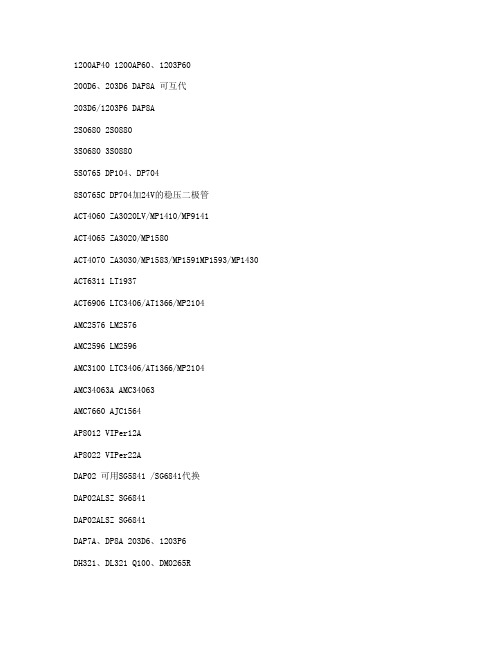
1200AP40 1200AP60、1203P60200D6、203D6 DAP8A 可互代203D6/1203P6 DAP8A2S0680 2S08803S0680 3S08805S0765 DP104、DP7048S0765C DP704加24V的稳压二极管ACT4060 ZA3020LV/MP1410/MP9141ACT4065 ZA3020/MP1580ACT4070 ZA3030/MP1583/MP1591MP1593/MP1430 ACT6311 LT1937ACT6906 LTC3406/AT1366/MP2104AMC2576 LM2576AMC2596 LM2596AMC3100 LTC3406/AT1366/MP2104AMC34063A AMC34063AMC7660 AJC1564AP8012 VIPer12AAP8022 VIPer22ADAP02 可用SG5841 /SG6841代换DAP02ALSZ SG6841DAP02ALSZ SG6841DAP7A、DP8A 203D6、1203P6DH321、DL321 Q100、DM0265RDM0465R DM/CM0565RDM0465R/DM0565R 用cm0565r代换(取掉4脚的稳压二极管)DP104 5S0765DP704 5S0765DP706 5S0765DP804 DP904FAN7601 LAF0001LD7552 可用SG6841代(改4脚电阻)LD7575PS 203D6改1脚100K电阻为24KOB2268CP OB2269CPOB2268CP SG6841改4脚100K电阻为20-47KOCP1451 TL1451/BA9741/SP9741/AP200OCP2150 LTC3406/AT1366/MP2104OCP2160 LTC3407OCP2576 LM2576OCP3601 MB3800OCP5001 TL5001OMC2596 LM2596/AP1501PT1301 RJ9266PT4101 AJC1648/MP3202PT4102 LT1937/AJC1896/AP1522/RJ9271/MP1540SG5841SZ SG6841DZ/SG6841DSM9621 RJ9621/AJC1642SP1937 LT1937/AJC1896/AP1522/RJ9271/MP1540STR-G5643D STR-G5653D、STR-G8653DTEA1507 TEA1533TEA1530 TEA1532对应引脚功能接入THX202H TFC719THX203H TFC718STOP246Y TOP247YVA7910 MAX1674/75 L6920 AJC1610VIPer12A VIPer22A[audio01]ICE2A165(1A/650V.31W);ICE2A265(2A/650V.52W);ICE2B0565(0.5A/650V.23W):ICE2B165(1A/650V.31W);ICE2B265(2A/650V.52W);ICE2A180(1A/800V.29W);ICE2A280(2A/800.50W).KA5H0365R, KA5M0365R, KA5L0365R, KA5M0365RN# u) t! u1 W1 B) R, PKA5L0365RN, KA5H0380R, KA5M0380R, KA5L0380R1、KA5Q1265RF/RT(大小两种体积)、KA5Q0765、FSCQ1265RT、KACQ1265RF、FSCQ0765RT、FSCQ1565Q这是一类的,这些型号的引脚功能全都一样,只是输出功率不一样。


en 60335-2-29 英文标准EN 60335-2-29 is a British Standard that specifies the safety requirements for electrical appliances for household and similar purposes. This standard specifically focuses on the safety requirements for electric heating appliances, such as electric radiators, electric blankets, and electric heating pads.The standard covers various aspects of safety, including protection against electric shock, mechanical hazards, and fire hazards. It also includes requirements for insulation, temperature control, and control devices.Some of the specific requirements outlined in EN 60335-2-29 include:1. Protection against electric shock: The standard specifies requirements for insulation, grounding, and protective measures to prevent electric shock to users.2. Mechanical hazards: It includes requirements for construction, stability, and protection against moving parts to prevent injury to users.3. Fire hazards: The standard outlines requirementsfor materials used in the construction of the appliances to ensure they are not prone to ignition or contribute to the spread of fire.4. Temperature control: It specifies requirements for temperature limiters and control devices to prevent overheating and potential fire hazards.5. Control devices: The standard includes requirements for switches, timers, and othercontrol devices to ensure their safety and reliability.6. Marking and instructions: EN 60335-2-29 also covers requirements for marking and instructions to provide users with clear guidance on the safe and proper use of the appliances.It is important for manufacturers, retailers, and consumers to adhere to this standard to ensure the safety of electrical heating appliances in households and similar environments. Compliance with EN 60335-2-29 helps to minimize the risk of electric shock, fire, and other hazards associated with these appliances.。
No. EX##-OMJ1011SI UnitEX245-SPR2-X35Digital Input ModuleEX245-DX1-X36Digital Output ModuleEX245-DY1-X371. Safety (4)2. Product Summary (8)2.1. Feature (8)2.2. Structure (9)3. General Specifications (10)4. Valve Manifold (11)5. Installation (12)5.1. Mounting (12)5.2. Wiring (14)6. Commissioning (16)6.1. Switch setting (16)6.2. Configuration (19)6.3. Parameterisation (21)6.4. Connection to the SIEMENS PLC S7 (23)7. Diagnosis (27)7.1. Setting the diagnostic mode (27)7.2. Standard diagnostic information (29)7.3. Extended diagnostic Information (31)7.4. Diagnostic usage when connected to the SIEMENS PLC S7 (36)8. SI Unit - EX245-SPR2-X35 (39)8.1. Parts and description (39)8.2. Specifications (40)8.3. LED indicators (41)8.4. Block diagram (43)9. Digital Input Module - EX245-DX1-X36 (44)9.1. Parts and description (44)9.2. Specifications (45)9.3. Wiring (46)9.4. Process data (46)9.5. LED indicators (47)9.6. Block diagram (47)10. Digital Output Module - EX245-DY1-X37 (48)10.1. Parts and description (48)10.2. Specifications (49)10.3. Wiring (50)10.4. Process data (50)10.5. LED indicators (51)10.6. Block diagram (51)11. Dimensions (52)11.1.VQC2000 manifold (52)11.2. VQC4000 manifold (53)12. Troubleshooting (54)12.1. EX245-SPR2-X35 (54)12.2. EX245-DX1-X36 (55)12.3. EX245-DY1-X37 (55)This manual contains essential information to prevent possible injury and damage to users and others, and property, and to ensure correct handling.Please confirm understanding the definition of the following messages (signs) before going on to read the text, and always follow the instructions.Also read carefully the instruction manual of relevant equipment or apparatus before use.♦Operator♦ This manual has been written for those who have knowledge of machinery and apparatus that use pneumatic equipment and have full knowledge of assembly, operation and maintenance of such equipment.♦ Please read this manual carefully and understand it before assembling, operating or providing maintenance to the product.♦Usage Restrictions♦ This product is designed for use in general equipment for factory automation. Never use this product with equipment or apparatus that directly concerns human lives*1, or which malfunction or failure can cause a huge loss.*1: Equipment or apparatus that directly matters human life means the following:•Medical equipment such as life support systems or equipment used in operating rooms.•Compulsory equipment required by law such as the Fire Prevention Law, Construction Law and etc.•Equipment or apparatus that conforms with those mentioned above.♦ Contact our sales department when the product is planned to be used for the system*2 including equipment that concerns itself with the safety of persons or that seriously affects the public. This usage needs special consideration*3.*2: The system including equipment that concerns itself with the safety of persons or that seriously affects the public means the following:•Nuclear reactor control systems in nuclear power plants, safety protection systems or othersystems important for safety in nuclear power facilities•Driving control systems of mass transportation systems, and flight control systems•Equipment or apparatus that comes into contact with foods or beverages*3: Special consideration means discussing usage with our engineers to establish a safe system designed as fool-proof, fail-safe, redundant and etc.♦ Special consideration of safety or maintainability should be taken to prevent hazard or loss caused by a failure or malfunction that is likely to occur in certain probability due to environmental stress (deterioration).The special consideration means fully review of the equipment or apparatus in design stage and to establish a backup system in advance such as a redundant system or fail-safe system.NOTE♦ Follow the instructions given below when handling the product:Otherwise a risk of damage or operating failure could result.♦ The instructions on selection (installation, wiring, environment of use, adjustment, operation and maintenance) described below must also be followed.∗Product specifications•Operate the product with the specified voltage.Operation with a voltage beyond specifications could cause malfunction or damage of the product.•Reserve a space for maintenance.Be sure to keep space for maintenance when designing layout of the product.•Do not remove labels.Otherwise maintenance error and misreading of an operation manual could cause damage or malfunction. It may also result in nonconformity to safety standards.♦ Precautions on handling∗Installation•Do not drop, hit or apply excessive shock to the product.•Follow the specified tightening torque on installation.Excessive tightening torque can break screws.∗Wiring•Do not bend the cables, or apply excessive force by placing heavy objects on them.Wiring with bending stress or tensile stress can cause breakage of the cables.•Connect wires and cables correctly.Incorrect wiring can damage the product depending on condition of the wiring.•Do not connect wires while the power is on.Otherwise it can damage the product causing damage or malfunction.•Do not lay wires or cables with power cable or high-voltage cable in the same wiring route.Otherwise the wires to the product can be interfered with noise or induced surge voltage from power lines or high-voltage lines causing malfunction.Lay the wires to the product and each device separate from those for power lines or high- voltage lines.•Verify the insulation of wiring.Poor insulation (interference with other circuit, poor insulation between terminals, etc.) canintroduce excess voltage or current to the product or device causing damage.•Take proper measurements against noise by noise filter etc. when the product is incorporated in equipment or devices.Otherwise interference from noise can cause malfunction.•Low safety voltage (SELV/PELV in accordance with EN 60950) must be used for all power and signal voltages.∗Environment•Select the proper type of protection according to the environment of operation.IP65 protection is achieved when the following conditions are met.(1) By connecting the product properly with the communication line and power cable with M12connectors at both ends, and(2) By installing the product and manifold valves properly.Use suitable cover, etc. when installing in an environment where water always splashes onthe product.NOTE•Take sufficient shielding measures when the product is installed in the following places.Insufficient measures can cause malfunction or failure.Verify the effect of the measures after installation of the product in equipment or devices:(1) A place where noise due to static electricity is generated(2) A place where electric field strength is high(3) A place where there is radioactive irradiation(4) A place near power line(5) A place where water splashes on the product•Do not use the product near by a place where electric surges are generated.Internal circuit elements of the product can deteriorate or break when equipment generating a large surge (electromagnetic lifter, high frequency induction furnace, motor, etc.) is located near the product. Provide surge protection, and avoid interference.•Use the product equipped with surge absorber when a surge-generating load such as a relay or solenoid valve is driven directly.Direct drive of a surge-generating load can damage the product.•Prevent foreign matter such as remnant of wires from entering the product.Take proper measures for the remnant not to enter the product in order to prevent failure ormalfunction.•Do not expose the product to vibration or impact.Otherwise failure or malfunction could be caused.•Keep within the specified ambient temperature range.Otherwise failure or malfunction could be caused.•Do not use the product in a place where temperature suddenly changes even if it stays within the specified range.•Do not expose the product to heat radiation from a heat source located nearby.Otherwise malfunction could be caused.∗Adjustment and Operation•Use precision screwdriver with small flat blade when setting DIP switch and rotary switch.∗Maintenance•Before performing maintenance, make sure to turn off the power supply, stop supplied air, release the residual air in the piping into the atmosphere, and verify that the pneumatic system is open to the air.Otherwise an unexpected operation of a system component can occur.•Perform maintenance and check regularlyOtherwise an unexpected malfunction of the system can occur due to a malfunction of theproduct.•Perform a proper functional check.Stop operation when an abnormality is observed such that the device does not work properly.Otherwise an unexpected malfunction of the system component can occur.•Do not use solvents such as benzene, thinner or other to clean the product.It can damage the surface of the body and erase the indication on the body.Use a soft cloth to remove stains. For heavy stains, use a cloth soaked with diluted neutraldetergent and fully squeezed, then wipe up the stains again with a dry cloth.2.1. FeatureThis SI Unit represents a PROFIBUS DP slave for SMC pneumatic valves. It is also designed for digital and analogue data control by connecting compatible EX245 modules. They can be used within rugged industrial environments, especially within the automotive plants.The SI Unit has following properties:(1) IP65 protection(2) Up to 32 solenoid valves(3) Up to 128 digital inputs(4) Up to 64 digital outputs independent of solenoid valves(5) Up to 8 modules (limited by the total current consumption)(6) Integrated diagnostic and protection function(7) Galvanically isolated power supplies (PROFIBUS DP, US1 for logic / sensors, US2 for valves /loads, US3 and 4 for external loads)(8) Free module configurationCompatible EX245 modules:・EX245-DX1-X36 (16 digital inputs)・EX245-DY1-X37 (8 digital outputs)2.2. StructureNo. ComponentsFunction 1 SI UnitFieldbus and valve interface and supply voltage to modules 2 Digital input moduleSupply voltage to sensors and input digital data 3 Digital output moduleOutput to electric loads 4 End plateEnd plate of module 5 Solenoid valves Operate pneumatic devicesFig. 2-1 System structure 2. Digital input module(EX245-DX1-X36)3. Digital output module(EX245-DY1-X37)4. End plate (EX245-EA2-X50)5. Solenoid valves1. SI Unit(EX245-SPR2-X35)Table. 3-1 EX245 series general specificationsItem SpecificationRated voltage 24 VDC1 msec. or lessAllowable instantaneouselectrical stopProtection class IP65 (when fully installed or fitted with protective cover)(comply with IEC 60529)Applicable standard CE Marking *Withstand voltage 500 VAC 1 min. (between FE and all accessible terminals) Insulation resistance 10 MΩ or more(500 VDC is given between FE and all accessible terminals) Ambient temperature Operation: -5 °C to 50 °CStorage: -20 °C to 60 °CAmbient humidity 35% to 85% RH (non-condensing)Vibration resistance 5 Hz to 9 Hz (constant amplitude) 1.75 mm9 Hz to 150 Hz (constant acceleration) 4.9 m/s22 hours for each direction X, Y and Z(comply with IEC 61131-2)Impact resistance 147 m/s2 is given 3 times for each direction X, Y and Z(comply with IEC 61131-2)Operating environment No corrosive gas*Note: EMC directive (89/336/EEC)EN 61000-6-2/2001, EN 55011/1998+A1+A2EX245 product series can use the following valve manifold:・VQC1000 / 2000 / 4000・SV1000 / 2000 / 3000 / 4000・VSR8-4/8-2, VSS8-4/8-2Refer to catalogue and technical operation manual for details of solenoid valves, manifolds, etc. Contact SMC sales for its compatibility with other solenoid valves.5.1. MountingCautionTo prevent manifold components being damaged, apply the recommended tightening torque.Mount the manifold using the 8 mounting positions on the base with screws.Required screws are as follows:① 2 x M5 (End plate: torque = 1.5 N⋅m)② 2 x M5 (SI Unit: torque = 1.5 N⋅m)③ 4 x M4 or M5 (Valve manifold: refer to valve manifold catalogue)Fig. 5-1 Required screwsAll manifolds are mounted using 8 screws (except VQC4000 which uses 7 screws).5.1.1. Valve manifold connectionConnect the valve manifold with the 2 screws on the SI Unit.Fig. 5-2 Valve manifold connectionCautionFor protection rating of IP65 to be ensured, apply the recommended tightening torque and make sure that the O-ring are positioned correctly on the screw.5.1.2. Module connectionConnect the modules with the 2 modular adaptor assemblies and a joint assembly.① 2 x Modular adaptor assembly (torque = 1.3 N⋅m)② 1 x Joint assemblyFig. 5-3 Module connectionCaution・For protection rating of IP65 to be ensured, modular adaptor assemblies and joint assembly must be installed between each module correctly.・To prevent the modules and assemblies being damaged, apply the recommended tightening torque.5.2. WiringCautionTo prevent damage, all voltages to the SI Unit must be turned off (i.e. de-energized) before the modules are installed or removed.Wire the grounding cable, Bus cables and Power cable.① M5, FE terminal screw (torque = 1.5 N ⋅m) ② M12, Bus connector (IN) ③ M12, Bus connector (OUT) ④7/8”, Power connectorFig. 5-4 Screw and connector allocation5.2.1. Bus / Power connectionThe Bus (OUT) is used for looping through connections. If the bus cable is not looped through, cover the Bus (OUT) with a dummy cap so that a protection rating of IP65 is ensured.Caution・ For reasons of EMC a secure connection to the cable shield must be established on the Bus /(IN / OUT) and Power.・ Power and bus lines must be installed correctly.・ To prevent components of the EX245 from being damaged, the supply lines for the electronicsand for the load voltage must be protected externally with a fuse.③②④IN OUTRemarksN.C. 1 1 N.C. Not usedBus_A 2 2 Bus_APROFIBUS A (galvanically isolated) N.C. 3 3 N.C.Not usedBus_B 4 4 Bus_BPROFIBUS B (galvanically isolated)Shield5 5 ShieldShieldFig. 5-5 Pin allocation of Bus connectorPin Remarks 1 0 V (US2) 2 0 V (US1) 3 FE 4 24 V (US1) 5 24 V (US2)Fig. 5-6 Pin allocation of Power connector5.2.2. FE terminalThe SI Unit must be connected to FE (Functional Earth) to divert electromagnetic interference. Connect to the grounding cable with FE terminal screw on the SI Unit.The other end of the grounding cable should be terminated to ground potential.5.2.3. Sensor / Load connectionRegarding the wiring of each module, refer to following section:・ EX245-DX1-X36: 9.3, page-46 ・ EX245-DY1-X37: 10.3, page-50IN / PinsOUT / Sockets6.1. Switch settingThe switches are located inside the SI Unit, behind the Function switch cover on the front.Using the DIP / rotary switches:・ Unscrew the cover and hinge it upwards.・ The DIP / rotary switches can be adjusted with a small flat-blade screwdriver. The points of thearrows on the rotary switches should be aligned with the required numbers.・ Tighten the cover again, making sure that the seals are positioned correctly. (torque = 0.3 N ⋅m)Fig. 6-1 Accessing the DIP / rotary switches6.1.1. Setting the PROFIBUS addressSet the PROFIBUS address with the switches. Valid addresses are 1 to 125. Set the hundreds with DIP switch, the tens with the left-hand rotary switch and the units with the right-hand rotary switch. Changing address will not take effect until the SI Unit has been powered OFF and then back ON again.Fig. 6-2 Switches for setting the PROFIBUS addressHundreds Tens UnitsSwitch setting Value Switch setting Value Switch setting ValueON 1OFF 00 to 9 0 to 9 0 to 90 to 9Tens Units O N 1 2 3Diagnostic modePROFIBUS addressMaximum number of valvesPROFIBUS networkOFF ON ModeADDRESSx100 x10 x14Termination6.1.2. Setting the maximum number of valvesSelect the maximum number of valves connected with the SI Unit. Changing this setting will not take effect until the SI Unit has been powered OFF and then back ON again.Fig. 6-3 Switch for setting the maximum number of valves6.1.3. Setting the diagnostic modeThe SI Unit supports three diagnostic modes. Changing this setting will not take effect until the SI Unit has been powered OFF and then back ON again.Switch settingNo. 2 No. 3Mode DescriptionOFF OFF Mode 1Extended diagnostic information consists of only simpledevice-related diagnostic data.OFF ON Mode 2Extended diagnostic information consists of detaileddevice-related diagnostic data.ON OFF Mode 3Extended diagnostic information consists of device-related,module-related and channel-related diagnostic data.Fig. 6-4 Switches for setting the diagnostic modeSwitch settingDescriptionON Max. 32 coils. OFF Max. 16 coils.Maximum number of valvesDiagnostic mode6.1.4. Setting the PROFIBUS network terminationThe end nodes on a PROFIBUS network must be terminated to avoid reflections on the bus lines.The SI Unit is equipped with a switch to enable termination. If the SI Unit is the end node on the network, the termination should be set to ON.ON OFF OFFFig. 6-5 Switch for setting the PROFIBUS network termination Switch Setting DescriptionON Termination is enabled.OFF Termination is disabled.6.2. ConfigurationThe EX245-SPR2-X35 is a modular station that consists of several modules. Setup your DPmaster’s software to reflect the configuration of your system.6.2.1. GSD file and symbol filesIn order to configure the EX245-SPR2-X35 with your DP master’s software the appropriate GSD file is required. In addition to slave-typical entries (ID Number, Revision, etc.), the GSD file alsocontains a selection of identifiers.In order to represent the EX245-SPR2-X35 in your DP master’s software the appropriate symbol files is required.Current GSD file and symbol files can be found on the Internet under PROFIBUS International: ・URL: ・GSD file: SMC_1410.gsd・Symbol files: EX245_2N.dib (standard case)EX245_2D.dib (diagnostic case)EX245_2S.dib (special operating mode)6.2.2. Module identifierEach module has its own identifier.Table. 6-1 Overview of identifier for EX245-SPR2-X35DP identifierModule name Occupied bytesSiemens IEC 61158 Valves (32 coils) 4 bytes 32DO 23hValves (16 coils) 2 bytes 16DO 21hbytes 16DI 11h EX245-DX1-X36 2byte 8DO 20h EX245-DY1-X37 16.2.3. Configuration stepsEnter the identifiers corresponding to the actual module layout in your configuration programaccording to the following steps. If the configuration does not match the actual layout, theconnection to the DP master cannot be established.Configuration steps:・Enter the identifier of “Valves (32 coils)” or “Valves (16 coils)” as Module 0, according to switch setting for maximum number of valves (refer to 6.1.2, page-16).・Enter the identifiers of all modules that are connected on the left hand side of the SI Unit (max. 8 modules).Fig. 6-6 Example of assignment of module numbers6.3. ParameterisationThe parameters associated with a PROFIBUS DP slave consist of standard parameters which all slaves must have, and other user-settable parameters which can be specified to change thebehavior of the slave (user parameters). Generally, users are allowed to set user parameters only.6.3.1. System parametersThe EX245-SPR1-X35 has the following system parameters.Table. 6-2 System parametersParameters Range of values Default MeaningUS1 Diagnosis EnableDisable Enable When this parameter is enabled, thesystem generates a diagnosticevent if it detects that US1 hasdropped.US2 Diagnosis EnableDisable Disable When this parameter is enabled, thesystem generates a diagnosticevent if it detects that US2 hasdropped.US3 Diagnosis EnableDisable Disable When this parameter is enabled, thesystem generates a diagnosticevent if it detects that US3 hasdropped.US4 Diagnosis EnableDisable Disable When this parameter is enabled, thesystem generates a diagnosticevent if it detects that US4 hasdropped.6.3.2. Module parameters6.3.2.1. Module parameters for valvesThe “Valves (32 coils)” has the following module parameters:Table. 6-3 Module parameters of Valves (32 coils) Name Range of values Default MeaningHold/Clear: Valve Output 0 ClearHoldClearHold/Clear: Valve Output 1 ClearHoldClear… … …Hold/Clear: Valve Output 31 ClearHoldClearWhen a bus fault occurs, the outputcan be made to react in either of thefollowing ways:Clear: Clear outputHold: Hold last stateThe “Valves (16 coils)” has the following module parameters.Table. 6-4 Module parameters of Valves (16 coils) Name Range of values Default MeaningHold/Clear: Valve Output 0 ClearHoldClearHold/Clear: Valve Output 1 ClearHoldClear… … …Hold/Clear: Valve Output 15 ClearHoldClearWhen a bus fault occurs, the outputcan be made to react in either of thefollowing ways:Clear: Clear outputHold: Hold last state6.3.2.2. Module parameters for EX245-DX1-X36The EX245-DX1-X36 has no module parameters that you can set.6.3.2.3. Module parameters for EX245-DY1-X37The EX245-DY1-X37 has the following module parameters.Table. 6-5 Module parameters of EX245-DY1-X37 Name Range of values Default MeaningHold/Clear: Digital Output 0 ClearHoldClearHold/Clear: Digital Output 1 ClearHoldClear… … …Hold/Clear: Digital Output 7 ClearHoldClearWhen a bus fault occurs, the outputcan be made to react in either of thefollowing ways:Clear: Clear outputHold: Hold last state6.4. Connection to the SIEMENS PLC S7This section guides the user through the most important steps by means of a worked example. It illustrates how to correctly set up the master software “SIMATIC STEP 7 Version 5.3” to reflect the slave units configuration.6.4.1. Install the GSD fileThe GSD file for the EX245-SPR2-X35 must be installed into the “STEP 7”. There are two possible procedures for installing the file.6.4.1.1. Procedure A - Before starting the STEP 7・Copy the GSD file into the folder “…\Siemens\Step7\S7data\gsd”.・Copy the symbol file into the folder “…\Siemens\Step7\S7data\nsbmp”.・Start the STEP 7 program.・The EX245-SPR2-X35 module will automatically be entered into the folder “Additional Field Devices\Valves\SMC EX Series” of the dialogue window “Hardware Catalog”.6.4.1.2. Procedure B - After starting the STEP 7・Open the dialogue window “HW Config”.・Select the menu “Option > Install new GSD file”.・Select the GSD file from the subsequent dialogue box and confirm with OK.・Copy the bitmap file into the “…\Siemens\Step7\S7data\nsbmp” folder.・The EX245-SPR2-X35 module will automatically be entered into folder “Additional Field Devices\Valves\SMC EX Series” of the dialogue window “Hardware Catalog”.Fig. 6-7 EX245-SPR2-X35 module in Hardware Catalog6.4.2. Station selection・Drag the folder “EX245-SPR2-X35” onto the PROFIBUS line on the DP master (drag & drop).The dialogue window “Properties - PROFIBUS Interface” appears.・Select the address identical to the selected setting of switches in the node and confirm with OK.The symbol “EX245-SPR2-X35” appears on the PROFIBUS line.Fig. 6-8 Station selection of the EX245-SPR2-X356.4.3. ConfigurationFill in the configuration table with the modules that are present in your hardware ensuring thenumbers correspond to those allocated earlier.・Select the symbol “EX245-SPR2-X35” to be configured in the dialogue window “HW Config”.・Select the module in the dialogue window “Hardware Catalog”. Drag it onto the same line as slot1 in the configuration table.・Repeat this step for further modules. Drag these onto the next free line.Fig. 6-9 Configuration of the EX245-SPR2-X356.4.4. Parameterisation6.4.4.1. Setting of system parameters・Double click the symbol “EX245-SPR2-X35” on the PROFIBUS line. The dialogue window “Properties - DP Slave” appears.・Select the tab “Parameter Assignment”. The list with the parameters and the present active values will be displayed.・Click the value of the parameter you wish to modify. A dropdown list with the possible values will open up.・Modify the value by clicking and confirm with OK.Fig. 6-10 System parameters of the EX245-SPR2-X356.4.4.2. Setting of module parameters・Double click in the configuration table on the line of the module you wish to edit. The dialogue window “Properties - DP Slave” appears.・Continue as described in system parameters (above).Fig. 6-11 Module parameters of the Valve (32 coils)The slave diagnostics conform to IEC 61784-1:2002 Ed1 CP 3/1. The following sections describe what the slave diagnostics cover.7.1. Setting the diagnostic modeThe SI Unit supports three diagnostic modes. Changing this setting will not take effect until the SI Unit has been powered OFF and then back ON again.Switch setting No. 2 No. 3ModeDescriptionOFF OFF Mode 1Extended diagnostic information consists of only simple device-related diagnostic data.OFF ON Mode 2Extended diagnostic information consists of detaileddevice-related diagnostic data.ON OFF Mode 3Extended diagnostic information consists of device-related,module-related and channel-related diagnostic data.Fig. 7-1 Switch for setting the diagnostic modeFig. 7-2 Diagnostic possibilitiesDiagnostic mode7.1.1. Overview of diagnostic bytes Mode 1Table. 7-1 Overview of extended diagnostic bytes Mode 1 Byte Description Explanation0 to 5 Standard diagnostic information Specified by PROFIBUS DP standard6 Device-related diagnostic header Fixed 03h7 Device-related diagnostic byte 1 General diagnostic byte 18 Device-related diagnostic byte 2 General diagnostic byte 27.1.2. Overview of diagnostic bytes Mode 2Table. 7-2 Overview of extended diagnostic bytes Mode 2 Byte Description Explanation0 to 5 Standard diagnostic information Specified by PROFIBUS DP standard6 Device-related diagnostic header Fixed 0Dh7 Device-related diagnostic byte 1 General diagnostic byte 18 Device-related diagnostic byte 2 General diagnostic byte 29 Device-related diagnostic byte 3 Valve coils 0-15 diagnostics10 Device-related diagnostic byte 4 Valve coils 16-31 iagnostics11 Device-related diagnostic byte 5 Module 1 diagnostic byte12 Device-related diagnostic byte 6 Module 2 diagnostic byte13 Device-related diagnostic byte 7 Module 3 diagnostic byte14 Device-related diagnostic byte 8 Module 4 diagnostic byte15 Device-related diagnostic byte 9 Module 5 diagnostic byte16 Device-related diagnostic byte 10 Module 6 diagnostic byte17 Device-related diagnostic byte 11 Module 7 diagnostic byte18 Device-related diagnostic byte 12 Module 8 diagnostic byte7.1.3. Overview of diagnostic bytes Mode 3Table. 7-3 Overview of extended diagnostic bytes Mode 3 Byte Description Explanation0 to 5 Standard diagnostic information Specified by PROFIBUS DP standard6 Device-related diagnostic header Fixed 02h7 Device-related diagnostic byte 1 General diagnostic byte 18 Module-related diagnostic header Fixed 43h9 Module-related diagnostic byte 1 The relevant module has a diagnosticmessage10 Module-related diagnostic byte 2 The relevant module has a diagnosticmessage11 Channel-related diagnostic 1 (Module X) Contains module number12 Channel-related diagnostic 2 (Module X) Channel number and input / output13 Channel-related diagnostic 3 (Module X) Fault type and channel type14 Channel-related diagnostic 1 (Module Y) Contains module number15 Channel-related diagnostic 2 (Module Y) Channel number and input / output16 Channel-related diagnostic 3 (Module Y) Fault type and channel type… … …35 Channel-related diagnostic 1 (Module Z) Contains module number36 Channel-related diagnostic 2 (Module Z) Channel number and input / output37 Channel-related diagnostic 3 (Module Z) Fault type and channel type。