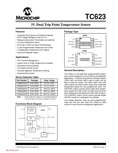
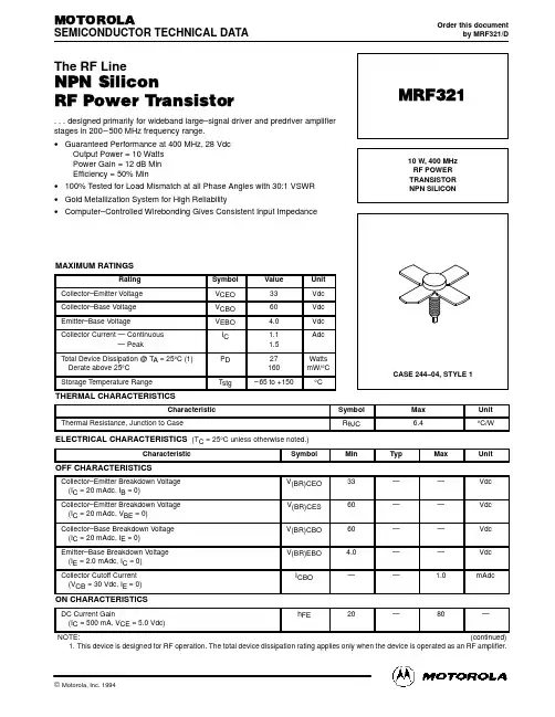
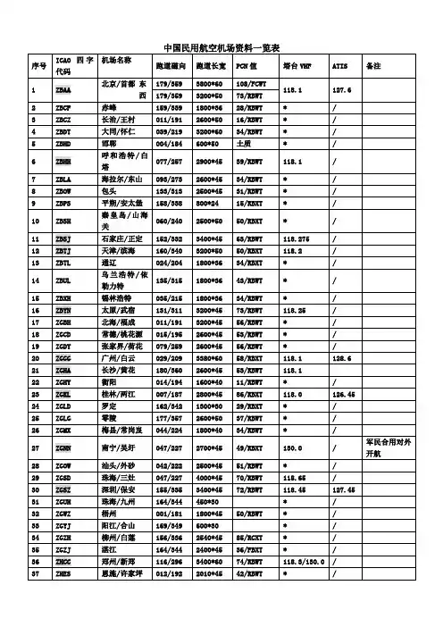
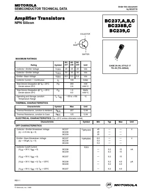
TC244资料
- 格式:pdf
- 大小:471.48 KB
- 文档页数:19
TC244
786-×488-PIXEL CCD IMAGE SENSOR
SOCS016B – NOVEMBER 1989 – REVISED DECEMBER 1991
Copyright © 1991, Texas Instruments Incorporated
2-1POST OFFICE BOX 655303 • DALLAS, TEXAS 75265•High-Resolution, Solid-State Image Sensorfor NTSC Color TV Applications•8-mm Image-Area Diagonal, CompatibleWith 1/2” Vidicon Optics•755 (H) x 242 (V) Active Elements inImage-Sensing Area•Advanced On-Chip Signal Processing•Low Dark Current•Electron-Hole Recombination Antiblooming•Dynamic Range . . . More Than 70 dB•High Sensitivity•High Photoresponse Uniformity•High Blue Response•Single-Phase Clocking•Separate Outputs for Each Color (RGB)•Solid-State Reliability With No ImageBurn-in, Residual Imaging, ImageDistortion, Image Lag, or Microphonics description
The TC244 is a frame-transfer charge-coupled device (CCD) image sensor designed for use in single-chip colorNTSC TV applications. The device is intended to replace the 1/2-inch vidicon tube in applications requiring smallsize, high reliability, and low cost.
The image-sensing area of the TC244 is configured into 242 lines with 786 elements in each line. Twenty-nineelements are provided in each line for dark reference. The blooming protection incorporated into the sensor isbased on recombining excess charge with charge of opposite polarity in the substrate. This antiblooming isactivated by supplying clocking pulses to the antiblooming gate, which is an integral part of each image-sensingelement.
The sensor is designed to operate in an interlace mode, electronically displacing the image-sensing elementsby one-half of a vertical line during the charge integration period in alternate fields, effectively increasing thevertical resolution and minimizing aliasing. The single-chip color-sensing capability of the TC244 is achievedby laminating a striped color filter with RGB organization on top of the image-sensing area. The stripes areprecisely aligned to the sensing elements, and the signal charge columns are multiplexed during the readoutinto three separate registers with three separate outputs corresponding to each individual color.
This MOS device contains limited built-in gate protection. During storage or handling, the device leads should be shorted togetheror the device should be placed in conductive foam. In a circuit, unused inputs should always be connected to SUB. Under nocircumstances should pin voltages exceed absolute maximum ratings. Avoid shorting OUTn to ADB during operation to preventdamage to the amplifier. The device can also be damaged if the output terminals are reverse-biased and an excessive current isallowed to flow. Specific guidelines for handling devices of this type are contained in the publication Guidelines for HandlingElectrostatic-Discharge-Sensitive (ESDS) Devices and Assemblies available from Texas Instruments.SUB 1IAG 2ABG 3ADB 4OUT3 (B) 5OUT2 (G) 6OUT1 (R) 7AMP GND 8CDB 9SUB 1020 SUB19 IAG18 ABG17 SAG16 SRG315 SRG214 SRG113 NC12 TRG11 IDBDUAL-IN-LINE PACKAGE(TOP VIEW)
NC – No internal connection
PRODUCTION DATA information is current as of publication date.Products conform to specifications per the terms of Texas Instrumentsstandard warranty. Production processing does not necessarily includetesting of all parameters.元器件交易网www.cecb2b.comTC244
786-×488-PIXEL CCD IMAGE SENSOR
SOCS016B – NOVEMBER 1989 – REVISED DECEMBER 1991
2-2POST OFFICE BOX 655303 • DALLAS, TEXAS 75265description (continued)
A gated floating-diffusion detection structure with an automatic reset and voltage reference incorporated on-chipconverts charge to signal voltage. The signal is further processed by a low-noise, state-of-the-art correlatedclamp-sample-and-hold circuit. A low-noise, two-stage, source-follower amplifier buffers the output andprovides high output-drive capability.
The TC244 is built using TI-proprietary virtual-phase technology, which provides devices with high blueresponse, low dark signal, good uniformity, and single-phase clocking.
The TC244 is characterized for operation from –10°C to 45°C.
functional block diagram
Dark Reference Elements
Clearing DrainAmplifiers
OUT2 (G)OUT3 (B)ADBABGIAG2
3
4
5
6
7OUT1 (R)
8AMP GNDCDB9SRG3
SRG2
SRG1
TRGIDB
12141516SAG17ABGIAG
1819
Storage AreaBlooming ProtectionImage Area WithTop Drain
11 DummyElementsGates, and Serial RegistersMultiplexer, Transfer11
detailed description
The TC244 consists of four basic functional blocks: (1) the image-sensing area, (2) the image-storage area,(3) the multiplexer block with serial registers and transfer gates, and (4) the low-noise signal-processingamplifier block with charge-detection nodes. The location of each of these blocks is identified in the functionalblock diagram.元器件交易网www.cecb2b.com