HPS丝杠样本
- 格式:pdf
- 大小:976.02 KB
- 文档页数:9

VERINS HYDRAULIQUES DETECTION MAGNETIQUEDouble EffetSERIE VBMJoints ISOPression de service: 250 barAlésages: 25 à 80 mCARACTERISTIQUES GENERALESEXTREMITE DE TIGE∅ Alésage 25 32 40 50 63 80 ∅ MM (∅ Tige)16 18 22 28 36 45 LM 20 20 25 30 40 50 M M10 M12 M16 M20 M27 M33 NF M10 M12 M16 M20 M27 M33 K13 16 20 24 32 40TARAUDEEFILETEEVBM TYPE M1VBM TYPE M2Possibilités de montagePression>160bar avec clavetage Pression>160bar sans clavetage∅ Alésage25 32 40 50 63 80∅ MM (Ø Tige)16 18 22 28 36 45L*+ course ±1mm, 52 65 71 82 91 104C o u r s e m i n i15 15 15 15 20 25C o u r s e m a x i100 100 100 100 100 100125100160A 657585B 17 20 23 27 25 32C.H11 10 12 12 15 20 2417132110.5D 8.510.512095765563E 50G 11 11 11 12 17 20759512063H 4555I* 26 27 27 30 41 47ΦJ 1/4" 1/4" 1/4" 1/4" 1/2" 1/2"K 13 16 20 24 32 40M M8 M10 M10 M12 M16 M20MP 16 20 20 24 32 35N 33 38 40 44 50 60PC 2 3 3 5 5 7Y 7 10 10 10 14 14N o t a:E n c a s d e c o u r s e s>100m m,p r ièr e d e n o u s c o n s u l t e r.VBM TYPE M3VBM TYPE M12Possibilités de montagePression>160bar avec clavetage Pression>160bar sans clavetage∅Alésage25 32 40 50 63 80∅ MM (∅Tige)16 18 22 28 36 45L*+ Course ±1mm, 52 65 71 82 91 104C o u r s e m i n i15 15 15 15 20 25C o u r s e m a x i100 100 100 100 100 10016010012575A 6585B1 21 25 27 29 32 39C.H11 10 12 12 15 20 2417211310.510.5D 8.5761209563E 5055G1 8 10 10 13 16 2175951206355H 45I* 26 27 27 30 41 47K 13 16 20 24 32 40M M8 M10 M10 M12 M16 M20MP 16 20 20 24 32 35N 33 38 40 44 50 6012.712.711 11 12.7O+0.2 11PC 2 3 3 5 5 7T 4 4 4 5 6 6J o i n t s t o r i q u e s R6 R6 R6 R7 R7 R7 Y 7 10 10 10 14 14N o t a:E n c a s d e c o u r s e>100m m,p r ièr e d e n o u s c o n s u l t e r.VBM TYPE M4VBM TYPE M5VBM TYPE M8VBM TYPE M9N o t a:E n c a s d e c o u r s e>100m m,p r ièr e d e n o u s c o n s u l t e r.∅ Alésage 25 32 40 50 63 80 ∅ MM (∅ Tige)16 18 22 28 36 45 L*+ Course ±1mm, 52 65 71 82 91 104 C o u r s e m i n i15 15 15 15 15 15 C o u r s e m a x i100 100 100 100 100 100A 65 75 85 100 125 160D 8.5 10.5 10.5 13 17 21E 50 55 63 76 95 120F 30 35 40 45 65 80H 45 55 63 75 95 120K 13 16 20 24 32 40M M8 M10 M10 M12 M16 M20MP 16 20 20 24 32 35 O+0.211 11 11 12.7 12.7 12.7∅Q 3X6 3X6 5X10 6X10 8X10 10X10T 4 4 4 5 6 6 J o i n t s t o r i q u e s R6 R6 R6 R7 R7 R7 Y 7 10 10 10 14 14V 29 33 37 44 55 70X 8 9 10 11 15 18VBM TYPE M6VBM TYPE M7 VBM TYPE M10VBM TYPE M11N o t a:E n c a s d e c o u r s e s>100m m,p r ièr e d e n o u s c o n s u l t e r.∅ Alésage25 32 40 50 63 80 ∅ MM (∅Tige)16 18 22 28 36 45 L*+ Course ±1mm, 52 65 71 82 91 104 C o u r s e m i n i15 15 15 15 15 15 C o u r s e m a x i100 100 100 100 100 100A 65 75 85 100 125 160B 17 20 23 27 25 32D 8.5 10.5 10.5 13 17 21E 50 55 63 76 95 120F 30 35 40 45 65 80G 11 11 11 12 17 20H 45 55 63 75 95 120ΦJ 1/4" 1/4" 1/4" 1/4" 1/2" 1/2"K 13 16 20 24 32 40 M M8 M10 M10 M12 M16 M20 MP 16 20 20 24 32 35 Y 7 10 10 10 14 14TABLEAU DES FORCESForces développées en poussant (daN),Pression (bar),∅AlésageSection alésagecm²80 100 160 200 25025 4.90 392 490 784 980 1225 32 8.04 644 800 1286 1608 2100 40 12.56 1004 1256 2009 2512 3140 50 19.63 1570 1963 3140 3926 4970 63 31.17 2493 3117 4987 6234 7792 80 50.26 4020 5026 8041 10052 12565Forces développées en tirant (daN),Pression (bar),∅Alésage∅TigeSection annulaire cm²80 100 160 200 25025 16 2.90 232 290 464 580 725 32 18 5.50 440 550 880 1100 1375 40 22 8.76 700 876 1401 1752 2190 50 28 13.48 1078 1348 2156 2696 3370 63 36 20.99 1680 2099 3358 4198 5247 80 45 34.36 2748 3436 5497 6872 8590DETECTION MAGNETIQUE BMF305BMF 305 KCaractéristiques techniques pour le détecteur magnétique BMF 305 KPNP contact a fermeture / communicationpositiveIntensité de communication nominaleH nRated operating field strength H n 1,2 kA/m Intensité de travail H aAssured operating field strength H a≥2 kA/mHystérésis Hysteresis ≤45% de H nDérive thermique du point d’enclTemperature drift ≤0,3%/°C Tension d’emploi U BSupply voltage U B 10…30 V DCChute de tension Ud pour I e ≤100 mA Voltage drop U d for I e ≤100 mA ≤3.1 V Tension d’isolement nominale U i Rated insulation voltage U i 75 V DC Courrant admissible permanent I aRated operational current I a200 mA Courant à vide I 0 dét/non détNo-load supply current ≤30 mA/≤10 mACourant résiduel I rOff-state current I r≤80µA Protection contre les inversions depolarité Protected against polarity reversalYes Protection contre les courts-ciruits Short circuit protection Yes Capacité de charge admissible Load capacitance ≤1 µF Température ambiante T a Ambient temperature range T a-25…+70°C Catégorie d’utilisation Utilization categories DC 13 Degré de protection Degree of protection IP67 Matériau du boîtier Housing material LCPType de raccordement Type of connectionConnecteurCable with connector Connecteur proposéConnectorBKS-S 48 PU05C o n n e c t e u r d r o i t “B K S 48” 3 m d e c a b l e m o u l é d a n s l a m a s s eCOMMENT COMMANDERSERIE 250b a r VBM ALESAGE Indiquer le diamètre en mm25,32,40,50,63,80***P l a n d e p o s e c l a v e téM1 M2 M3 M12FIXATION ETALIMENTATIONP l a n d e p o s e l o n g i t u d i n a lM4 M5 M6 M7 M8 M9 M10 M11EXTREMITE DE TIGE FiletéeTaraudéeFTETANCHEITE Joint standard Buna N + 80°C max 1 M O D I F I C A T I O N Préciser toute modification ou options S C O U R S E1m m Indiquer la course réelle en mm (voir tableau)***D E T E C T E U R M A G N E T I Q U E P o s i t i o n P1 P2N o t a:E n c a s d e c o u r s e>100m m,p r ièr e d e n o u s c o n s u l t e r.ATTENTION !!!Afin d’éviter toute erreur de contact, aucun champ magnétique extérieur supérieur à 1Ka/m ne doit entourer le cylindre. Ancun matériau ferrique ne doit se trouver directement à proximité des capteurs magnétiques. Prévoir des protections contre les copeaux ferriques. La température ambiante ne doit pas être supérieure à + 70°C.。
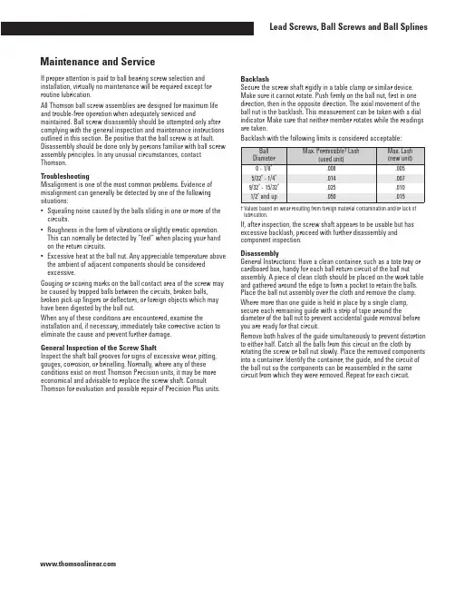
If proper attention is paid to ball bearing screw selection and installation, virtually no maintenance will be required except for routine lubrication.All Thomson ball screw assemblies are designed for maximum life and trouble-free operation when adequately serviced and maintained. Ball screw disassembly should be attempted only after complying with the general inspection and maintenance instructions outlined in this section. Be positive that the ball screw is at fault. Disassembly should be done only by persons familiar with ball screw assembly principles. In any unusual circumstances, contact Thomson.TroubleshootingMisalignment is one of the most common problems. Evidence of misalignment can generally be detected by one of the following situations:•Squealing noise caused by the balls sliding in one or more of the circuits.•Roughness in the form of vibrations or slightly erratic operation. This can normally be detected by “feel” when placing your hand on the return circuits.•Excessive heat at the ball nut. Any appreciable temperature above the ambient of adjacent components should be considered excessive.Gouging or scoring marks on the ball contact area of the screw may be caused by trapped balls between the circuits, broken balls, broken pick-up fingers or deflectors, or foreign objects which may have been digested by the ball nut.When any of these conditions are encountered, examine the installation and, if necessary, immediately take corrective action to eliminate the cause and prevent further damage.General Inspection of the Screw ShaftInspect the shaft ball grooves for signs of excessive wear, pitting, gouges, corrosion, or brinelling. Normally, where any of these conditions exist on most Thomson Precision units, it may be more economical and advisable to replace the screw shaft. Consult Thomson for evaluation and possible repair of Precision Plus units.BacklashSecure the screw shaft rigidly in a table clamp or similar device. Make sure it cannot rotate. Push firmly on the ball nut, first in one direction, then in the opposite direction. The axial movement of the ball nut is the backlash. This measurement can be taken with a dial indicator. Make sure that neither member rotates while the readings are taken.Backlash with the following limits is considered acceptable:† Values based on wear resulting from foreign material contamination and/or lack of lubrication.If, after inspection, the screw shaft appears to be usable but has excessive backlash, proceed with further disassembly and component inspection.DisassemblyGeneral Instructions: Have a clean container, such as a tote tray or cardboard box, handy for each ball return circuit of the ball nut assembly. A piece of clean cloth should be placed on the work table and gathered around the edge to form a pocket to retain the balls. Place the ball nut assembly over the cloth and remove the clamp. Where more than one guide is held in place by a single clamp, secure each remaining guide with a strip of tape around the diameter of the ball nut to prevent accidental guide removal before you are ready for that circuit.Remove both halves of the guide simultaneously to prevent distortion to either half. Catch all the balls from this circuit on the cloth by rotating the screw or ball nut slowly. Place the removed components into a container. Identify the container, the guide, and the circuit of the ball nut so the components can be reassembled in the same circuit from which they were removed. Repeat for each circuit.General Description Array A Thomson ball screw is a force and motion transfer device belonging to the family of power transmission screws. It replaces sliding friction of the conventional power screw with the rolling friction of bearing balls. The balls circulate in hardened steel races formed by concave helical grooves in the screw and nut. All reactive loads between the screw and nut are carried by the balls which provide the only physical contact between these members.As the screw and the nut rotate relative to each other, the balls are diverted from one end and carried by ball guides to the opposite end of the nut. This recirculation permits unrestricted travel of the nut in relation to the screw.Method I:Ball nuts using a deflector return system are identified by threaded deflector studs extending through holes in the nut and the guide clamp. Lock nuts on the deflector studs are used to secure the clamps that hold the guides in place.Method II:Ball nuts with pick-up fingers are identified by the finger projections integral with the guide. In this method, capscrew fasteners are used to fasten the clamp that holds the guide in place. Pick-up Finger Method:Refer to the Component Inspection section. Deflector Method:To remove the deflectors from the ball nut assembly, remove the ball nut from the screw shaft. The ball nut must be rotated since the deflectors engage loosely in the screw ball grooves and act as a thread. The deflectors now can be removed from the opposite ends of the ball nut so that you can use them forreference during component inspection.Component Inspection and ReplacementBalls: If there is more than one circuit in the ball nut, count the balls in each of the separate containers to be sure each has the same number (within a variation of three balls). Check random samples (about 1/4 of the balls for a circuit) for the following:•True roundness, with a .0001 in. maximum variation.•Signs of scuffing or fish scaling.•More than .0001 in. diameter variation between balls of the same circuit.Where the random sampling shows balls out of round, signs of scuffing or variation of diameter in excess of .0001 in., or short count in any circuit, all balls in the unit must be replaced with a complete set of new balls. Ball kits are available from Thomson.To ensure proper operation and long life of the serviced assembly, it is imperative that the diameters of all the replacement balls do not vary in excess of .00005 in. If Thomson kits are not used for service, make sure the balls meet the above specification. (Note: Use only chrome alloy steel balls, Grade 25 or better. Carburized balls or carbon steel balls will not provide adequate life.) See Ball Chart table.Deflectors:Examine the ends of the deflectors for wear or brinelling. Wear can be determined by comparison with the unused ends of the two outside deflectors. Since these ends have not been subjected to wear from balls, they are in a like-new condition. Where wear or brinelling is evident, it is best to replace the deflectors with new ones. Pick-up Fingers: Inspect the pick-up fingers, which consist of short extensions at the end of the guides. Replace with new guides if a ball brinell impression appears on the tip. Remove any burrs on the fingers. If the guides were distorted during removal, replace with new guides. Ball Nut:Inspect the internal threads of the ball nut for signs of excessive wear, pitting, gouges, corrosion, spalling, or brinelling in the ball groove area. On large ball nuts, running the tip of your finger along the groove which is accessible will enable you to detect a secondary ridge in the ball groove area when wear is excessive or brinelling has occurred. (The extended lead of a mechanical pencil can also be used as a groove probe.) If inspection indicates any of these flaws, the ball nut assembly should be replaced.Wipers:Prolonged use and environmental conditions will generally determine the condition of wipers. After cleaning wipers, reassemble over the screw shaft to determine whether a snug fit is maintained over the complete contour of the screw shaft. Any loose fitting or worn wipers should be replaced. Wiper kits are available for Thomson ball screws.Note: If the assemblies have had extended use, it is recommended that all low cost items be replaced with new parts (i.e., balls, guides, deflectors, clamps). These can be ordered by simply referring to the assembly part number purchased.ReassemblyCleaning: Clean all components with a commercial solvent and dry thoroughly before reassembly.Deflector Method: Where the ball nut is equipped with deflectors, install these and secure temporarily by running the lock nuts down the studs and tightening.General Instructions: Position the ball nut on the screw shaft. Ball nuts with deflectors have to be screwed on. Other ball nuts will slide on. Using dowels with an O.D. approximately equal to the diameter of the balls, center the ball nut grooves with the shaft grooves by inserting dowels into each of the ball nut return circuit holes.Remove the second dowel from one end. With the ball return holes up, fill the circuit with balls from the container corresponding to that circuit. Turning the screw in the ball nut will help to feed the balls into the groove. When the circuit is full, the balls will begin to lift the end dowel from its position. To be sure there are no voids, lightly tap the top bearing ball and see if the end dowel moves.The remaining ball in the container should fit into one of the halves of the return guide with space for about three to six left.Note: There must be some free space in the ball circuit so the balls will roll and not skid. Do not try to add extra balls into the circuit. Place a dab of bearing grease at each end of the half return guide to hold the balls in place. Now, take the other half of the return guide and place it over the half guide you have filled with balls and insert two ends of the ball guide into the respective hole in the ball nut. Seat by tapping gently with a rawhide or plastic mallet.Note: Where more than one ball circuit must be filled in the ball nut, tape the ball return circuit to the ball nut to prevent accidental removal. Repeat the filling procedure for the remaining circuits. With all ball circuits filled and all return guides in place, secure the return guides with the retaining clamp.CAUTION: Care should be taken to ensure that balls are not accidentally trapped between circuits in units having pick-up fingers. In deflector units, the deflectors will fill this space.Inspection: Wrap tape around the ball grooves at the ends of the screw shaft to prevent the ball nut from rolling off. Now inspect the assembly for free movement of the ball nut along the entire stroke. There should be no binding, squeal, or roughness at any point. Reducing Backlash: Backlash can be reduced by replacing all the balls with a larger size. If the diameters of the bearing balls are increased by .001 in., backlash is decreased by .003 in. (Ball kits are available for these applications.)Ball Chart (Grade 25 or Better)240Inspection and Existing Preload Check: Whenever possible, the complete ball screw assembly should be removed from the machine prior to a thorough inspection. Preliminary screw inspection can be made while the unit is still in the machine. Preload can be determined by measuring movement of the nut in respect to the screw shaft. Clamp an indicator to the screw shaft with its probe resting on the face of the nut. Apply a load to the machine carriage in both directions. Be sure that the screw cannot rotate or move axially. Any measurable backlash between the ball nut and screw is an indication that preload does not exist. (See Figure 18.)If no backlash exists, proceed further as outlined to determine whether proper preload remains in the unit. Existing preload, Wp, can be determined by measuring torque, Tp, using the following formula: Wp =Tp.007where:Wp = Preload force, in lb.Tp = Torque, in lb-in. (due to preload only) Note: The above check is to determine preload only, and does not take into account torque due to seal drag or operating load.Torque can be measured by means of a spring scale mounted to any projection on the ball nut or by means of a lever or rod secured to the ball nut. In taking this measurement, be sure the exact lever arm distance is measured. (See Figure 18.) This measurement (inch) multiplied by the scale reading (lb.) equals Tp (torque lb-in.). Existing preload can now be determined using the above formula.Preload adjustment of a Precision ball screw (Figure 18) requires no disassembly. Possible removal of the ball nut from the machine housing may be necessary to expose the adjusting nut. Disassembly: If in doubt about disassembly of preloaded ball nuts, contact Thomson Application Engineering. If the unit is to be disassembled for general repair, follow the steps previously outlined in this section.If being disassembled for preload adjustment, follow the guidelines except remove only one-half of the ball nut assembly to an arbor. If a standard arbor is not available, one can be made from a piece of shafting or tubing with a diameter approximately .005 inch less than the root diameter of the ball grooves in the screw shaft. Both halves of the ball nut will come apart as soon as the last ball in the nut is free of the grooves in the screw shaft. It is not necessary to remove the other half from the screw.Preload Adjustment: The adjusting nut unit in Figure 18 can be adjusted to the desired preload with the use of additional shims. To make further adjustment, loosen the set screw lock located on the periphery of the lock nut. Use a spanner wrench to rotate the adjusting nut to the desired setting. Recheck the preload.For all other standard units in Figure 18, a shim increase of .001 inch will, as a general rule, increase preload by 500 to 1,000 lb. This varies depending upon screw size; therefore, some judgement and trial and error may be necessary before the desired preload is achieved. Preload force, Wp, can be determined by measuring torque, Tp, after the desired preload has been established using the following formula: Tp = .007 x Wpwhere:Tp = torque, lb-in. (due to preload only)Wp = preload force, lb.This section is intended to provide basic necessary information to properly service and maintain Thomson ball screws. Other forms of preloaded units may be encountered which have been designed for particular applications. Please contact Thomson Application Engineering for other specific information.Figure 18。

丝杠计算选型手册
丝杠计算选型手册是一种重要的工具,用于指导用户如何选择合适的丝杠规格,以确保满足特定的应用需求。
以下是丝杠计算选型手册中的一些主要内容:
1. 丝杠选型基础:介绍丝杠的种类、特点和应用范围,帮助用户了解不同丝杠的适用场景。
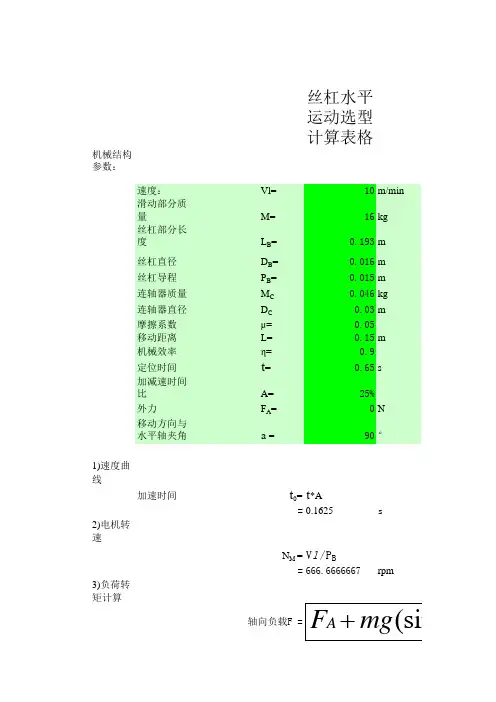
2. 丝杠参数计算:根据丝杠的规格参数,如导程、转速、载荷等,进行丝杠的计算和选型。
这部分内容需要详细介绍如何根据实际需求计算丝杠参数,并选择合适的规格。
3. 丝杠强度和刚度校核:对所选丝杠进行强度和刚度校核,以确保其能够承受工作载荷而不发生损坏。
这部分内容需要介绍如何进行校核,并提供相应的计算公式和图表。
4. 丝杠摩擦性能:介绍丝杠的摩擦性能参数,如摩擦系数、润滑方式等,以帮助用户了解丝杠在实际运行中的摩擦状况。
5. 丝杠寿命预测:根据丝杠的工作条件和使用环境,对其寿命进行预测,以便用户了解其使用寿命。
6. 丝杠安装和维护:介绍丝杠的安装和维护方法,包括安装前的准备、安装步骤、维护和保养等,以确保丝杠的正常运行和使用寿命。
7. 丝杠案例分析:通过实际案例的分析,帮助用户更好地理解丝杠的计算选型过程,并为其提供实际应用中的参考。
总之,丝杠计算选型手册旨在为用户提供全面、实用的指导,以帮助他们正确选择合适的丝杠规格,并确保其满足实际应用需求。
如果您需要更详细的信息,建议您参考专业机构或厂家提供的丝杠计算选型手册。
滚珠丝杠样本滚珠丝杠是一种高精度传动组件,一般应用于机床、汽车、航空航天、机器人等领域。
而滚珠丝杠样本是指供应商或制造商向客户提供的产品样本,主要作用是展示产品的特性、精度、质量等方面的参数,帮助客户选择适合自身需求的产品。
滚珠丝杠样本的种类滚珠丝杠样本的种类大致可以分为以下几类:1. 组件式样本:由滚珠丝杠主体、母杆、弹性元件等组成,客户可以直接拿到不同规格、不同类型的滚珠丝杠组件进行比较、测试。
2. 整机式样本:由滚珠丝杠、支架、电机、控制器等组成,客户可以直接操作、体验整个机器的性能和工作状态。
3. 静态展示样本:一般应用于展会、展览等场合,展示滚珠丝杠的结构、工作原理、优点等,客户可以通过观察和咨询了解产品。
4. 样品演示视频:随着科技的发展,越来越多的供应商开始提供样品演示视频,客户可以通过视频了解产品的外观、细节、工作效果等。
滚珠丝杠样本的作用滚珠丝杠样本的作用主要有以下几方面:1. 展示产品的特性及质量:通过不同类型的滚珠丝杠样本,客户可以了解产品的特性、精度及质量等方面的参数,帮助客户选择合适的产品。
2. 帮助客户了解产品的工作原理及性能:对于不熟悉滚珠丝杠工作原理的客户,供应商可以通过特制的静态展示样本或演示视频等方式,让客户更好地了解产品的性能及工作原理。
3. 加强客户对产品的信任感:通过提供可靠的滚珠丝杠样本,客户可以更好地了解产品的品质和可靠性,从而加强客户对产品的信任感,促进订单的成交。
4. 提高销售额:通过展示高质量的滚珠丝杠样本,能够吸引更多客户前来咨询和购买产品,从而有效提高供应商的销售额。
滚珠丝杠样本的制作滚珠丝杠样本的制作需要注意以下几点:1. 样本必须符合实际产品的标准:滚珠丝杠样本必须符合实际产品的规格、工艺、质量等标准,否则可能会误导客户,造成不良后果。
2. 样本的质量要保证:滚珠丝杠样本的质量要保证,主体部分要使用优质材料,精度要达到客户需要的要求,不能出现明显的误差或瑕疵。
国标丝杆的规格参数
国标丝杆是一种机械元件,主要用于传递旋转运动和直线运动之
间的转换,在工程机械、机器人等领域得到广泛应用。
根据国家标准,通常将丝杆的规格参数划分为以下几个方面:
1. 规格型号:丝杆的规格型号通常由螺距、丝径以及丝杆长度
来确定。
例如,M8*1.25-1000表示螺距为1.25mm,丝径为8mm,长度
为1000mm的丝杆。
2. 精度等级:丝杆的精度等级通常包括C3、C5、C7和C10等级,C3等级为精度最高的等级,C10等级为精度最低的等级。
这些等级主
要取决于丝杆的制造工艺和材料。
3. 工作载荷:丝杆的工作载荷指的是最大承受力,通常以公斤
或牛顿表示。
工作载荷的大小与丝杆的规格型号、材料以及制造工艺
等有关。
4. 转动阻力:丝杆的转动阻力取决于丝杆材料、润滑方式、使
用环境等多种因素。
5. 寿命:丝杆的寿命主要与丝杆的材料、精度等级、润滑方式
以及使用环境有关。
通常以公里或小时计算。
总的来说,选择合适的规格和参数的丝杆,可以确保机械设备的
正常工作和长寿命。
滚珠丝杠样本滚珠丝杠是一种常见的机械传动元件,广泛应用于各个领域的机械设备中。
它通过滚珠与螺纹杆的配合来实现转动运动或线性运动的传递。
为了确保滚珠丝杠的质量和性能达到要求,需要进行样本测试以评估其机械性能和使用寿命。
本文将介绍滚珠丝杠样本的测试方法和评估指标。
一、样本选择样本选择是滚珠丝杠测试的首要步骤。
从生产批次中随机选择一定数量的滚珠丝杠作为样本,确保样本的代表性和可靠性。
样本应该具有相似的性能参数和规格,以确保测试结果的可比性。
二、外观检查首先,对滚珠丝杠样本进行外观检查。
检查外观是否完整,有无明显的缺陷或磨损,如裂纹、凹陷或划痕等。
外观检查是评估滚珠丝杠质量的第一步,确保样本的基本完好。
三、尺寸测量接下来,对滚珠丝杠样本进行尺寸测量。
主要包括螺纹杆的直径、导轨的距离、滚珠直径等关键尺寸的测量。
测量时需要使用精确的测量工具,并按照规定的方法和标准进行测量。
尺寸测量结果将用于后续的性能测试和评估。
四、运动平稳性测试运动平稳性是评估滚珠丝杠性能的重要指标之一。
运动平稳性测试可以通过装配样本到测试装置上,并进行空载或负载的转动运动来进行。
观察滚珠丝杠运动过程中是否有异常,如噪声、振动或卡滞等。
运动平稳性测试结果将反映滚珠丝杠的转动精度和稳定性。
五、承载能力测试承载能力是滚珠丝杠的另一个关键性能指标。
承载能力测试可以通过施加一定载荷到样本上,并观察其变形或应力情况来进行。
测试时需要确定合适的载荷大小和测试时间,以保证测试结果准确可靠。
承载能力测试结果将用于确定滚珠丝杠的最大负载能力和安全工作范围。
六、回转精度测试回转精度是滚珠丝杠线性运动的重要指标之一。
回转精度测试可以通过将样本装配到测试装置上,以一定速度和距离进行正反转动,并记录回转过程中的误差情况来进行。
测试时需要使用精密的测量工具和装置,并按照标准的测试方法进行操作。
回转精度测试结果将用于评估滚珠丝杠的运动精度和重复性。
七、使用寿命测试使用寿命是评估滚珠丝杠可靠性和耐久性的重要指标。
丝杠规格什么是丝杠?丝杠是一种用于转换旋转运动和直线运动的机械传动装置。
它通常由一个螺纹轴和一个带有螺纹的螺母组成。
通过旋转螺纹轴,螺母可以沿着螺纹轴的轴向移动,实现直线运动。
丝杠的应用丝杠广泛应用于各种机械设备和工业领域,例如机床、自动化设备、升降平台等。
它们被用来提供精确的线性运动,使机械设备能够快速、准确地完成各种任务。
丝杠规格的重要性丝杠规格对于机械设备的性能和运行效果至关重要。
不同规格的丝杠具有不同的特点和适用范围。
在选择合适的丝杠规格时,需要考虑以下几个关键因素:1. 螺距螺距是指螺纹轴上单位长度内的螺纹数量。
螺距越大,同样的旋转角度下,螺母在轴向上的移动距离就越大,速度也就越快。
根据实际需求确定螺距大小,以满足所需的速度和精确度。
2. 导程误差导程误差是指螺纹轴与螺母之间的偏差量。
导程误差越小,丝杠的精确度就越高。
在选择丝杠规格时,需要根据机械设备的精度要求来确定导程误差的允许范围。
3. 轴径和螺纹剖面轴径和螺纹剖面是丝杠规格的另外两个重要参数。
轴径越大,丝杠的承载能力越强。
选择合适的螺纹剖面可以提高丝杠的效率和耐久性。
如何选择合适的丝杠规格?选择合适的丝杠规格需要考虑机械设备的具体要求和应用场景。
以下是一些选择丝杠规格的基本步骤:1. 确定线性运动需求首先需要确定机械设备需要实现的线性运动需求,包括所需的速度、精度和承载能力等。
2. 确定螺距和导程误差根据线性运动需求,确定合适的螺距和导程误差范围。
螺距的选择将直接影响运动速度,导程误差的选择将影响运动精度。
3. 确定轴径和螺纹剖面根据机械设备的承载要求和运动效率要求,选择合适的轴径和螺纹剖面。
较大的轴径可以提高丝杠的承载能力,合适的螺纹剖面可以提高丝杠的效率和耐久性。
总结丝杠规格是机械设备中的重要参数,影响着设备的性能和运行效果。
选择合适的丝杠规格需要考虑螺距、导程误差、轴径和螺纹剖面等因素,并根据机械设备的具体需求来确定。
正确选择丝杠规格将有助于提高设备的运动速度、精确度和承载能力,提高生产效率和产品质量。
丝杆垫片规格尺寸表一、引言丝杆垫片是一种常用的密封材料,广泛应用于机械设备、汽车、航空航天等领域。
为了确保垫片的质量和可靠性,制定了丝杆垫片的规格尺寸表,以便生产和使用过程中的准确选择。
二、丝杆垫片规格尺寸表下面是一份常见的丝杆垫片规格尺寸表,其中包括垫片的外径、内径、厚度等参数。
1. 型号:G1/4- 外径:15mm- 内径:9.5mm- 厚度:1.5mm2. 型号:G3/8- 外径:19mm- 内径:12.5mm- 厚度:2mm3. 型号:G1/2- 外径:24mm- 内径:16.5mm- 厚度:2.5mm4. 型号:G3/4- 外径:30mm - 内径:20.5mm - 厚度:3mm 5. 型号:G1- 外径:38mm - 内径:25.5mm - 厚度:3.5mm 6. 型号:G1 1/4 - 外径:45mm - 内径:32mm - 厚度:4mm 7. 型号:G1 1/2 - 外径:52mm - 内径:38mm - 厚度:4.5mm 8. 型号:G2- 外径:65mm - 内径:51mm - 厚度:5mm以上为部分丝杆垫片规格尺寸表,实际应用中还有更多尺寸可供选择。
三、选择丝杆垫片的注意事项在选择丝杆垫片时,需要根据具体的使用环境和要求来确定合适的规格尺寸。
以下是一些选择垫片的注意事项:1. 温度要求:根据使用环境的温度,选择适用于该温度范围的垫片材料和尺寸。
2. 压力要求:根据系统的工作压力,选择合适的垫片材料和厚度,以确保密封效果。
3. 化学性质:如果丝杆垫片会接触到特定化学物质,需选择耐腐蚀性能好的垫片材料。
4. 耐磨性要求:如果丝杆垫片会有较大的摩擦和磨损,需选择耐磨性好的垫片材料和合适的厚度。
5. 安装空间:根据安装空间的限制,选择合适尺寸的垫片,确保安装顺利进行。
四、丝杆垫片的材料选择丝杆垫片的材料也是选择的重要因素,常见的材料有橡胶、塑料、金属等。
根据不同的应用场景和要求,选择合适的材料可以提高垫片的使用寿命和密封效果。