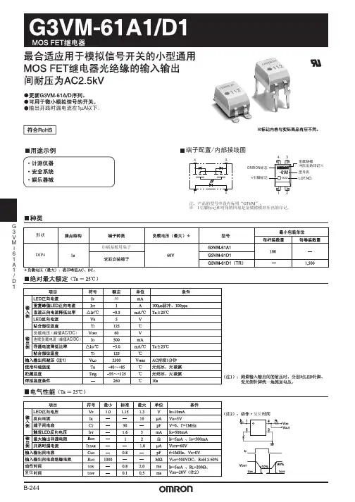
欧姆龙继电器G7S_E
- 格式:pdf
- 大小:231.79 KB
- 文档页数:4
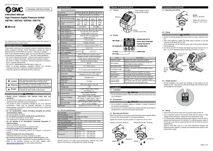
Instruction ManualHigh Precision Digital Pressure Switch ISE70G / ISE75G / ISE76G / ISE77GThe intended use of the pressure switch is to measure the pressure of fluid and to provide an output signal.These safety instructions are intended to prevent hazardous situations and/or equipment damage. These instructions indicate the level of potential hazard with the labels of “Caution,” “Warning” or “Danger.”They are all important notes for safety and must be followed in addition to International Standards (ISO/IEC) *1), and other safety regulations. *1)ISO 4414: Pneumatic fluid power - General rules relating to systems. ISO 4413: Hydraulic fluid power - General rules relating to systems.IEC 60204-1: Safety of machinery - Electrical equipment of machines. (Part 1: General requirements)ISO 10218-1: Manipulating industrial robots -Safety. etc.∙ Refer to product catalogue, Operation Manual and Handling Precautions for SMC Products for additional information. ∙ Keep this manual in a safe place for future reference.CautionCaution indicates a hazard with a low level of risk which, ifnot avoided, could result in minor or moderate injury.WarningWarning indicates a hazard with a medium level of riskwhich, if not avoided, could result in death or serious injury.DangerDanger indicates a hazard with a high level of risk which, ifnot avoided, will result in death or serious injury.Warning∙ Always ensure compliance with relevant safety laws and standards.∙ All work must be carried out in a safe manner by a qualified person in compliance with applicable national regulations.∙ This product is class A equipment intended for use in an industrial environment. There may be potential difficulties in ensuring electromagnetic compatibility in other environments due to conducted or radiated disturbances.∙ Do not disassemble, modify (including changing the printed circuit board) or repair. An injury or failure can result.∙ Do not operate the product outside of the specifications. Do not use for flammable or harmful fluids.Fire, malfunction or damage to the product can result.∙ Do not operate in an atmosphere containing flammable or explosive gases.Fire or an explosion can result.This product is not designed to be explosion proof. ∙ If using the product in an interlocking circuit:Provide a double interlocking system, for example a mechanical system.∙ Check the product for correct operation.Otherwise malfunction can result, causing an accident.∙ Do not touch terminals and connectors while the power is on. Otherwise electric shock, malfunction or product damage can result. ∙ Refer to the operation manual on the SMC website (URL: https:// ) for more safety instructions.2 Specifications2.1 General specifications2.2 IO-Link specifications IO-Link type Device IO-Link versionV1.1Communication speed COM2 (38.4 kbps) Min. cycle time2.3 msProcess data lengthInput Data: 2 byte, Output Data: 0 byte On request data comms. Available Data storage function Available Event function Available Vendor ID 131 (0x0083)Device IDISE70G-*-L2-* : 309 (0x0135) ISE75G-*-L2-* : 320 (0x0140) ISE76G-*-L2-* : 321 (0x0141) ISE77G-*-L2-* : 322 (0x0142)Special products (-X) might have specifications different from those shown in this section. Contact SMC for specific drawings.3.13.2 Display4 Installation4.1 InstallationWarning∙ Do not install the product unless the safety instructions have been read and understood. 4.2 EnvironmentWarning∙ Do not install in a location subject to vibration or impact in excess of the product’s specifications.∙ Do not mount in a location exposed to radiant heat that would result in temperatures in excess of the product specification.4.3 Mounting with BracketMount the bracket to the product using mounting screws supplied (M4x6 L (2 pcs)) then set the product in the required position.Tighten the bracket mounting screws to a torque of 0.76 ±0.1 N•m. Bracket A (Part No. ZS-50-A) Bracket B (Part No. ZS-50-B)4.44.5 PipingCaution∙ Before connecting piping make sure to clean up chips, cutting oil, dust etc.∙ After hand tightening, tighten the fitting using a spanner on the flat surfaces of the fitting (24 mm A/F).∙ When tightening, do not hold the upper part of the product (display) with the spanner.∙ For Rc1/4 and NPT1/4 threads the tightening torque must be 8 to 12 N•m. For G1/4 thread the tightening torque must be 4 to 5 N•m.4.6 Display Rotation∙ During installation, the upper part (display) of the product can be rotated by 336°. Take care as rotating the display with excessive force will damage the end stopper.4.7 Wiring∙ Connections should be made with the power supply turned off.∙ Use a separate route for the product wiring and any power or high voltage wiring. Otherwise, malfunction may result due to noise.∙ If a commercially available switching power supply is used, be sure to ground the frame ground (FG) terminal. If a switching power supply is connected, noise will be superimposed and will not meet the product specifications.Insert a noise filter such as a line noise filter/ferrite between the switching power supplies or change the switching power supply to the series power supply.ORIGINAL INSTRUCTIONSSpanneUpper part of productProduct No. ISE70G ISE75GISE76GISE77GApplicable fluid Fluids and Gases (non corrosive)P r e s s u r eRated pressure range 0 to 1.00 MPa 0 to 2.00 MPa 0 to 5.00 MPa 0 to 10.0 MPa Display / set pressurerange-0.105 to 1.050MPa-0.105 to 2.100 MPa -0.25 to 5.25 MPa -0.50 to10.50 MPa Minimum setting unit 0.001 MPa 0.01 MPa Proof pressure 3.0 MPa 5.0 MPa 12.5 MPa 30 MPaE l e c t r i c a lPower supply as switch output device 12 to 24 VDC ±10% with 10% Voltage ripple or less (p-p) Power supply as IO-Link device 18 to 30 VDC, including 10%voltage ripple (p-p)Current consumption 35 mA or less Protection Polarity protectionA c c u r a c yDisplay accuracy ±2% F.S.±1 digit (at ambient 25±3 o C)Repeatability±0.5% F.S.Temp. characteristics(25 o C standard) ±3% F.S.±5% F.S.S w i t c h o u t p u tOutput type NPN or PNP open collector output. Output mode Hysteresis mode, window comparator mode, error or switch output OFF.Switch operation Normal or reversed output.Max. Load current 80 mA Max. Applied voltage 30 V (NPN output)Internal voltage drop (Residual voltage) 1.5 V or less (Load current 80 mA) Delay time2.0 ms or less (for anti-chatter function:variable at 0 to 60 s / 0.01 step)Hysteresis or Window comparator mode Variable from 0 Short circuit protection ProvidedD i s p l a yUnits MPa, kPa, kgf/cm 2, bar, psiDisplay type LCDNumber of displays 3-screen display (Main display,sub display x 2)Display colour Main display: Red/Green, Sub display: OrangeNumber of display digitsMain display: 4 digits (7-segments) Sub display: 4 digits (Upper 1 digit 11-segments, 7-segments for other) Operation lightLED is ON when switch output is ON(OUT1, OUT2: Orange) Digital filterVariable from 0 to 30 s / 0.01 stepOrifice(Part no. ZS-48-A)Tighten the orifice to a torque of 1.5 ±0.1 N•m.Power supply / Output connector (M12 plug)Fitting(24 mm across flats)Part DescriptionOperation Light Displays the switch operating condition Main display Displays pressure measurement values and error codes (2 colour display). Sub display (left) Displays items (Orange)Sub display (right) Displays set values, peak and bottom values. (Orange)UP button Increases mode and ON/OFF set values. DOWN button Decreases mode and ON/OFF set values. SET button Changes the mode and confirms the settings. IO-Link status indicator light Displays OUT1 output communication status (SIO mode, start-up mode, operation mode) and the presence of communication data.Product code is displayed for 3 seconds∙ How to use connectorAlign the cable connector key groove with the product connector key to insert and rotate the knurled part of the connector.Connect the wires of the lead wire to the M12 connector as shown below. M12 Connector (code A)1) When used as a switch output device No. Name Colour Function 1 DC(+) Brown 12 to 24 VDC 2 OUT2 White Switch output 2 3 DC(-) Blue 0 V 4 OUT1 Black Switch output 12) When used as an IO-Link device No. Name Colour Function 1 L+ Brown 18 to 30 VDC 2 DO White Switch output 2 3 L- Blue 0 V4C/QBlackCommunication data (IO-Link) / Switch output 1 (SIO)Power is suppliedDefault settingsWhen the pressure exceeds the set value, the switch will be turned ON. When the pressure falls below the set value by the amount of hysteresis or more, the switch will be turned OFF.The default setting is to turn ON the pressure switch when the pressure reaches the centre of the atmospheric pressure and upper limit of the rated pressure range. If this condition is acceptable, then keep these settings.∙ 3 step setting mode (hysteresis mode)In 3 step setting mode, the set value (P_1 or n_1) and hysteresis (H_1) can be changed. Set the items on the sub display (set value or hysteresis) using the UP and DOWN button. When changing the set value, follow the operation below. The hysteresis setting can be changed in the same way.(1) Press the SET button once whenthe item to be changed is shown on the sub display. The set value on the sub display will start flashing.(2) Press the UP or DOWN button tochange the set value.When the UP and DOWN buttons are pressed and held simultaneously for 1 second or longer, the set value is displayed as [- - -], and the set value will be the same as the current pressure value automatically (snap shot function).Afterwards, it is possible to adjust the value by pressing the UP or DOWN button.(3) Press the SET button to complete the setting.The Pressure switch turns on within a set pressure range (from P1L to P1H) during window comparator mode. Set P1L, the lower limit of the switch operation, and P1H, the upper limit of the switch operation and WH1 (hysteresis) following the instructions given above.(When reversed output is selected, the sub display (left) will indicate [n1L] and [n1H].)∙ Set OUT2 in the same way.∙ Setting of the normal/reverse output switching and hysteresis/window comparator mode switching are performed using the function selection mode [F 1] OUT1 setting and [F 2] OUT2 setting.8 Simple Setting mode(1) Press and hold the SET button between 1 and 3 seconds inmeasurement mode. [SEt] is displayed on the main display. When the button is released while in the [SEt] display, the current pressure value is displayed on the main display, [P_1] or [n_1] is displayed on the sub display (left), and the set value is displayed on the sub display (right) (Flashing).(2) Change the set value using the UP and DOWN button,and press the SET button to set the value. Then, the setting moves to hysteresis setting. (The snap shot function can be used).(3) Change the set value with the UP or DOWN button,to the delay time of the switch output. (The snap shot function can be used).(4) The delay time of the switch output can be selected by pressing theUP or DOWN button at the ON and OFF point of the switch output. Delay time setting can prevent the output from chattering.The delay time can be set in the range 0.00 to 60.00 sec. in 0.01 sec. increments.(5) Press the SET button for less than 2 seconds to complete the OUT1setting. [P_2] or [n_2] is displayed on the sub screen (left). Continue with setting OUT2.Press and hold the SET button for 2 seconds or longer to complete the setting. The product will return to measurement mode. ∙ In window comparator mode, set P1L, the lower limit of the switch operation, and P1H, the upper limit of the switch operation, WH1 (hysteresis) and dtH / dtL (delay time) following the instructions given above. (when reversed output is selected, the sub display (left) will indicate [n1L] and [n1H]). ∙ Set OUT2 in the same way.9 Function Selection modeIn measurement mode, press the SET button between 3 and 5 seconds to display [F 0]. Select to display the function to be changed [F□□].Press and hold the SET button for 2 seconds or longer in function selection mode to return to measurement mode.*: Some products do not have all of the functions. If a function is not available or selected due to configuration of other functions, [- - -] is displayed on the sub display.10 Other Settings∙ Peak / Bottom value displayThe max. (min.) pressure from when power is supplied is detected and monitored. The value can be displayed on the sub display by pressing the UP or DOWN button in measurement mode. ∙ Snap Shot functionThe current pressure value can be stored to the switch output ON/OFF set point. When the set value and hysteresis are set, press the UP and DOWN button for 1 s or longer simultaneously. Then the set value of the sub display (right) shows [---], and the values corresponding to the current pressure values are automatically displayed. ∙ Zero-clear functionIn measurement mode, when the UP and DOWN buttons are pressed for 1 s or longer simultaneously, the main display shows [---] and then will reset to zero. The display will return to measurement mode automatically. ∙ Refer to the operation manual on the SMC website (URL: https// ) for further details of how to set these and other functions.11 Maintenance11.1 General MaintenanceCaution∙ Not following proper maintenance procedures could cause the product to malfunction and lead to equipment damage.∙ If handled improperly, compressed air can be dangerous.∙ Maintenance of pneumatic systems should be performed only by qualified personnel.∙ Before performing maintenance, turn off the power supply and be sure to cut off the supply pressure. Confirm that the air is released to atmosphere.∙ After installation and maintenance, apply operating pressure and power to the equipment and perform appropriate functional and leakage tests to make sure the equipment is installed correctly.How to reset the product after power cut or forcible de-energizing The setting of the product will be retained as it was before a power cut or de-energizing. The output condition is also basically recovered to that before a power cut or de-energizing, but may change depending on the operating environment.Therefore, check the safety of the whole installation before operating the product. If the installation is using accurate control, wait until the product has warmed up (approximately 10 to 15 minutes).12 Troubleshooting12.1 Error Indication If the error cannot be reset after the above measures are taken, or errorsother than the above are displayed, please contact SMC.13 Limitations of Use13.1 Limited warranty and Disclaimer/Compliance Requirements Refer to Handling Precautions for SMC Products.14 Product DisposalThis product shall not be disposed of as municipal waste. Check your local regulations and guidelines to dispose this product correctly, in order to reduce the impact on human health and the environment.15 ContactsRefer to or www.smc.eu for your local distributor/importer.URL : https:// (Global) https://www.smc.eu (Europe) SMC Corporation, 4-14-1, Sotokanda, Chiyoda-ku, Tokyo 101-0021, JapanSpecifications are subject to change without prior notice from the manufacturer. © 2021 SMC Corporation All Rights Reserved. Template DKP50047-F-085MPress the SET button once Press the SET button for 1 to 3 s Press the SET button for 3 to 5 s [3 step setting mode]Set value orhysteresis[Simple setting mode]Set value, hysteresis and delay time[Function selection mode]Change the function settings[Other settings]∙Zero clear ∙Snap lock ∙Key Lock。
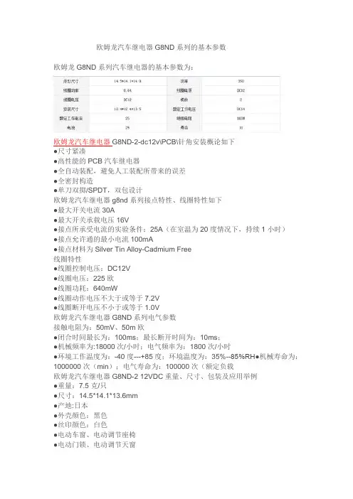
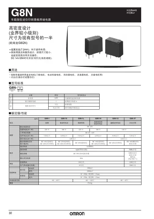
欧姆龙汽车继电器G8ND系列的基本参数欧姆龙G8ND系列汽车继电器的基本参数为:欧姆龙汽车继电器G8ND-2-dc12v\PCB\针角安装概论如下●尺寸紧凑●高性能的PCB汽车继电器●全自动装配,避免人工装配所带来的误差●全密封构造●单刀双掷/SPDT,双包设计欧姆龙汽车继电器g8nd系列接点特性、线圈特性如下●最大开关电流30A●最大开关承载电压16V●接点所承受电流的实验条件:25A(在室温为20度情况下,持续1小时)●接点允许通的最小电流100mA●接点材料为Silver Tin Alloy-Cadmium Free线圈特性●线圈控制电压:DC12V●线圈电压:225欧●线圈功耗:640mW●线圈动作电压不大于或等于7.2V●线圈断开电压不小于或等于1.0V欧姆龙汽车继电器G8ND系列电气参数接触电阻为:50mV、50m欧●闭合时间最长为:100ms;最长断开时间为:10ms;●机械频率为:18000次/小时;电气频率为:1800次/小时●环境工作温度为:-40度---+85度;环境温度为:35%--85%RH●机械寿命为:1000000次(min);电气寿命为:100000次(额定负载欧姆龙汽车继电器G8ND-2 12VDC重量、尺寸、包装及应用举例●重量:7.5克/只●尺寸:14.5*14.1*13.6mm●产地:日本●外壳颜色:黑色●丝印颜色:白色●电动车窗、电动调节座椅●电动门锁、电动调节天窗●车载冰箱●车载电气系统智能接线盒和模块的应用包装:1200只/箱管装(批量使用时,定货时需按1200的整数倍定)欧姆龙汽车电子向客户提供多种优质的汽车电子产品。
车窗自动升降系统、自动门锁、继电器等高性能产品,为提供安全、舒适的汽车生活做出贡献。
我们致力于技术的开发,生产新型的汽车电子组件,为实现更安全、更便利、更环保的人性化汽车社会而努力。
公司是欧姆龙一级代理商,价格优势明显,质量有保证,有大量库存,供货期短。
欢迎新老客户来电查询联系人:1 3 5 2 0 1 1 5 8 9 1 传0 1 0- 8 0 1 1 5 5 5 5转7 5 9 7 1 13F88L-RS173G3IV-PLKEB45P53G3JV-MANUAL3G3JZ-AB0223G3MV-A4075(YES)3G3MZ-A2004-ZV23G3MZ-A2007-ZV23G3MZ-A2015-ZV23G3MZ-A2055-ZV23G3RV-B418K-ZV13G3RV-B422K-ZV13G3RV-B4900-ZV13G3RX-A4220-Z43767-0010 MC374005-3066 UM5-3066C200H-ATT01C200H-BC101-V2C200H-CP114C200H-DA001C200H-DA002C200H-ID218C200H-ID501C200H-NC111C200H-OD501C200H-TS001C200HW-COM01C200HW-COM05-EV1C200HW-DRM21-V1C200HW-NC213C500-CE405CJ1W-OD263CP1W-20EDT1(Q)CP1W-40EDT1CPM1A-20EDT1CPM1A-40CDT-A-V1 CPM2A-20CDR-DCPM2A-20CDT-DCPM2A-30CDR-DCQM1-ID211CQM1-ME04RCQM1H-PLB21CRT1-AD04CS1D-CPU44SCS1H-CPU66HCS1H-CPU67HCS1W-BAT01CS1W-BI033CS1W-CN224CS1W-OC201CS1W-PDC55CS1W-SCU31-V1D4N-212GDRT1-232C2DRT2-AD04E2E-X10D1S DC12-24 2ME3X-DAC21-S 2ME5AZ-C3E5AZ-Q3E5AZ-R3E5CN-Q2HBT AC100-240 (Q)E5CN-R2HBT AC100-240 (Q)E5CN-R2T AC100-240 (Q)E5CZ-Q2 AC100-240E5CZ-R2MT AC100-240E5EZ-C3E6C2-CWZ6C 1024P/R 2M BY OMSG3JA-C425B AC100-240 FOR CHINA G3JA-C430B AC100-240 FOR CHINA G3JA-C437B AC100-240 FOR CHINA G3JA-D420B AC100-240 FOR CHINA G3JA-D425B AC100-240 FOR CHINA G3JA-D432B AC100-240 FOR CHINA G3JA-D451B AC100-240 FOR CHINA G3PB-535B-2N-VD DC12-24H5CN-XCN AC100-240H5F-BMKS2P DC12MKS3P-5 DC48MPT-CN550NS10-TV01B-V2R7A-CNB01S-ZR7A-CNB01SB-ZR7A-CNZ01C-ZR7D-AP04HR7D-AP08HR7D-BP01H-ZR7D-BP02H-ZR7D-BP02HH-ZR7D-BP04H-ZR7D-ZP01HR7D-ZP02HR7M-A40030-S1R7M-A75030-S1R7M-Z10030-S1ZR7M-Z20030-S1ZR88A-CNG01SB-ZR88D-GN01H-ML2-ZR88D-GN02H-ML2-ZR88D-GN04H-ML2-ZR88D-GN08H-ML2-ZR88D-GN10H-ML2-ZR88D-GN15H-ML2-ZR88D-GN20H-ML2-ZR88D-GN50H-ML2-ZR88D-GN75H-ML2-ZR88D-GT50H-ZR88D-GT75H-ZR88D-WN08H-ML2R88D-WN10H-ML2R88M-G10030H-BS2-Z R88M-G10030H-ZR88M-G1K020H-S2-Z R88M-G1K020H-ZR88M-G1K020T-BS2-Z R88M-G1K020T-S2-Z R88M-G1K020T-ZR88M-G1K030H-BS2-Z R88M-G1K030H-S2-Z R88M-G1K030H-ZR88M-G1K030T-S2-Z R88M-G1K520H-BS2-Z R88M-G1K520H-S2-Z R88M-G1K520H-ZR88M-G1K520T-BS2-Z R88M-G1K520T-S2-Z R88M-G1K520T-ZR88M-G1K530H-S2-Z R88M-G1K530T-S2-Z R88M-G20030H-BS2-Z R88M-G20030T-BS2-Z R88M-G20030T-S2-Z R88M-G2K010H-S2-Z R88M-G2K010H-ZR88M-G2K010T-S2-Z R88M-G2K010T-ZR88M-G2K020H-BS2-Z R88M-G2K020H-S2-Z R88M-G2K020H-ZR88M-G2K020T-S2-ZR88M-G2K030H-S2-Z R88M-G2K030T-S2-Z R88M-G3K010H-BS2-Z R88M-G3K010H-S2-Z R88M-G3K010H-ZR88M-G3K010T-S2-Z R88M-G3K020H-BS2-Z R88M-G3K020H-S2-Z R88M-G3K020H-ZR88M-G3K020T-S2-Z R88M-G3K020T-ZR88M-G3K030H-BS2-Z R88M-G3K030H-S2-Z R88M-G3K030H-ZR88M-G40030H-B-ZR88M-G40030H-BS2-Z R88M-G40030H-ZR88M-G40030T-BS2-Z R88M-G40030T-S2-Z R88M-G4K020H-BS2-Z R88M-G4K020H-S2-Z R88M-G4K020T-S2-Z R88M-G4K030H-BS2-Z R88M-G4K030H-S2-Z R88M-G4K510H-BS2-Z R88M-G4K510H-S2-Z R88M-G4K510T-S2-Z R88M-G5K020H-BS2-ZR88M-G5K030H-BS2-ZR88M-G5K030H-S2-ZR88M-G6K010H-BS2-ZR88M-G6K010H-S2-ZR88M-G75030H-BS2-ZR88M-G75030T-BS2-ZR88M-G75030T-S2-ZR88M-G7K515H-BS2-ZR88M-G7K515H-S2-ZR88M-G7K515T-S2-ZR88M-G90010T-S2-ZR88M-GP10030H-ZR88M-GP40030H-ZR88M-W10030T-S1SH-001-01MSH-001-03MSH-001-05MSH-001-10MV400-W23 3MV400-W24 3MWLCA32-41ZR-RX20A-CHROZR-RX40A-CHROZR-XRB1ZR-XRE1我公司是欧姆龙一级代理商,价格优势明显,质量有保证,有大量库存,供货期短。
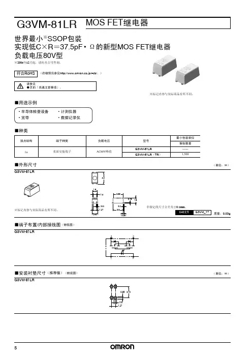
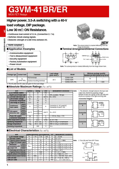
G3VM-41BR/ER Higher power, 3.5-A switching with a 40-Vload voltage, DIP package.Low 30 mΩ ON Resistance.•Continuous load current of 3.5 A. (Connection C: 7 A)•Switches minute analog signals.•Dielectric strength of 2,500 Vrms between I/O.■Application Examples■Terminal Arrangement/Internal Connections■List of Models*The AC peak and DC value are given for the load voltage.RoHS compliant Note: The actual product is marked differently from theimage shown here.•Communication equipment•Test & Measurement equipment•Security equipment•Factory Automation equipment•Power circuitOMRON logoNote: The actual product is marked differently from the image shown here. Package type Contact form TerminalsLoad voltage(peak value) *ModelMinimum package quantityNumber per stick Number per tape and reel DIP61a(SPST-NO)PCB terminals40 VG3VM-41BR50---Surface-mounting terminalsG3VM-41ERG3VM-41ER (TR)---1,50012G3VM-41BR/ERMOS FET RelaysG3VM-41BR/ER■Recommended Operating ConditionsUse the G3VM under the following conditions so that the Relay will operate properly.■Engineering Data■Safety Precautions•Refer to "Common Precautions" for all G3VM models.ItemSymbol MinimumTypical MaximumUnit Load voltage (AC peak/DC)V DD ------32V Operating LED forward current I F 51025mA Continuous load current (AC peak/DC)I O ------ 3.5AOperating temperatureTa−20 --- 65 °CLED forward current vs.Ambient temperatureContinuous load current vs.Ambient temperatureLED forward current vs.LED forward voltageContinuous load current vs.On-state voltageOn-state resistance vs.Ambient temperatureTrigger LED forward current vs. Ambient temperatureTurn ON, Turn OFF time vs.LED forward currentTurn ON, Turn OFF time vs.Ambient temperatureCurrent leakage vs.Ambient temperatureAmbient temperature Ta (°C)L E D f o r w a r d c u r r e n t I F (m A )I F - Ta03010204050-40100806040200-20I O - Ta-4010080 60 40 20-2000105Ambient temperature Ta (°C)C o n t i n u o u s l o a d c u rr e n t I O (A )I F - V FLED forward voltage V F (V)L E D f o r w a r d c u r r e n t I F (m A )0.0100.51 1.52I O - V ON-0.1-0.050.050.1-4-2-3-102134On-state voltage V ON (V)C o n t i n u o u s l o a d c u r r e nt I O (A )R ON - Ta30010204050Ambient temperature Ta (°C)O n -s t a t e r e s i s t a n c e R O N (m Ω)I FT - Ta-40-2010080604020012Ambient temperature Ta (°C)T r i g g e r L E D f o r w a r d c u r r e n t I F T (m A )t ON , t OFF - I F1011000.010.1110100LED forward current I F (mA)T u r n O N , T u r n O F F t i m e t O N , t O F F (m s )t ON , tOFF - Ta-40-20100806040200.011001010.1Ambient temperature Ta (°C)T u r n O N , T u r n O F F t i m e t O N , t O F F (m s)I LEAK - Ta-40-20100806040200.011001010.1Ambient temperature Ta (°C)C u r r e n t l e a k a g e I L E A K (n A )■Dimensions(Unit: mm) Note: The actual product is marked differently from theimage shown here.PCB Dimensions (Bottom View)Actual Mounting Pad Dimensions(Recommended Value, Top View)Note: The actual product is marked differently from the image shown here.+0.1−0.05PCB TerminalsWeight: 0.4 gSurface-mounting TerminalsWeight: 0.4 g• Application examples provided in this document are for reference only. In actual applications, confirm equipment functions and safety before using the product.• Consult your OMRON representative before using the product under conditions which are not described in the manual or applying the product to nuclear control systems, railroad systems, aviation systems, vehicles, combustion systems, medical equipment, amusement machines, safety equipment, and other systems or equipment that may have a serious influence on lives and property if used improperly. Make sure that the ratings and performance characteristics of the product provide a margin of safety for the system or equipment, and be sure to provide the system or equipment with double safety mechanisms.Cat. No. K138-E1-020412(0412)(O)Note: Do not use this document to operate the Unit. OMRON CorporationELECTRONIC AND MECHANICAL COMPONENTS COMPANY Contact: /ecb。
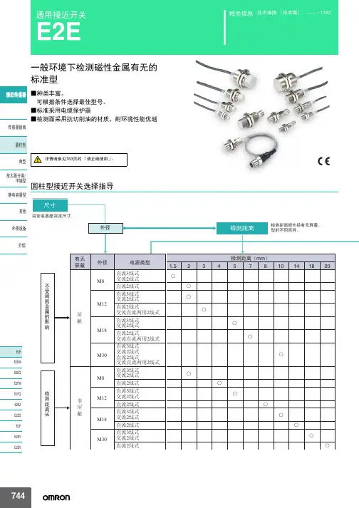
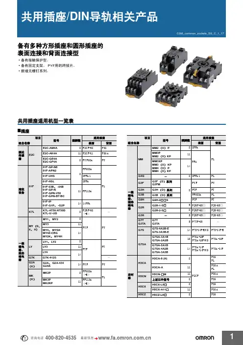
产品线 ..............................F-30共通注意事项 ..................350/后-7技术指南 (465)相关信息安全继电器单元G9S最适合向欧洲出口用设备的门开关紧急停止开关的紧急停止电路•通过小型安全继电器的开发,实现了2极型宽22.5mm 、3极型宽67.5mm 、5极型宽90mm 的纤细化。
•备有标准型和延迟断开单元。
•可以通过LED 确认内藏继电器的动作。
•实现手指保护构造。
•取得欧洲EN 标准、BIA 的认证。
•2极型中DIN 导轨安装和螺钉安装均可。
请参见414页「请正确使用」型号结构■型号标准G9S-□□□□-□□□① ② ③ ④ ⑤①接点结构(安全输出)2:2a 接点3:3a 接点5:5a 接点②接点结构(延迟断开输出)0:无2:2a 接点③接点结构(辅助输出)0:无1:1b 接点④输入结构无标记:可以1ch 、2ch 输入1:1ch 输入2:2ch 输入⑤延迟断开时间无标记:延迟断开时间无T01:1秒T04:4秒T10:10秒T015:1.5秒T05:5秒T30:30秒T03:3秒T06:6秒种类●标准型*辅助接点为1b 接点。
●选击注.所有型号的辅助接点都是1b 接点。
极数额定电压主接点输入ch 数型号2极DC 24V 2a1ch G9S-20012chG9S-20023极 *DC 24V 3a 1ch 、2ch 共用G9S-301AC 24V AC100V AC120V AC200V AC240V 5极 *DC 24V 5a G9S-501AC 24V AC100V AC120V AC200V AC240V极数额定电压主接点延迟断开接点输入ch 数延迟断开 时间型号3极DC 24V 3a 2a1ch 、2ch 共用1秒1.5秒3秒4秒5秒6秒10秒30秒G9S-321-T01 G9S-321-T015G9S-321-T03G9S-321-T04G9S-321-T05G9S-321-T06G9S-321-T10G9S-321-T30AC 24VAC100V AC120V AC200V AC240V额定值/性能■额定值●操作部注.温度+23℃时的数值。
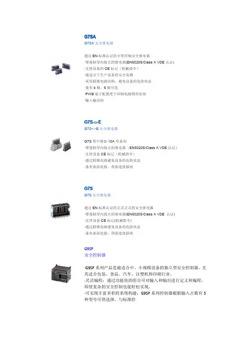
G7SA安全继电器通过EN 标准认证的小型纤细型安全继电器・带强制导向接点的继电器。
(EN50205/Class A VDE 认证)・备有机械的CE 标记(机械指令)。
・ 采用联锁电路结构,避免机械的危险状态。
・备有4极、6极产品。
・ 便于绘制PWB 图形的端子配置。
・输入输出间加强绝缘。
异极间也有一部分加强绝缘。
■型号标准■种类G7SA-□A □B①②①a 接点极数②b 接点极数2:2a 接点1:1b 接点3:3a 接点2:2b 接点4:4a 接点3:3b 接点5:5a 接点●安全继电器插座安全继电器G 7S A■额定值■安全继电器插座的特性■性能●开关部(接点部)注2.动作特性为线圈温度+23℃时的数值。
注3.最大连续容许电压为使用环境温度为+23℃时的最大值。
*1.P7SA-1□F 在+55~+85℃的环境中的连续通电电流6A 请按0.1A/℃来减小。
*2.测量条件:用DC500V 兆欧表测量,测量部位和耐压项目相同。
注.P7SA-1□F-ND (DC24V )请在环境温度为-25~+55℃的环境中使用。
*1. 测量条件:由DC5V1A 电压下降法测得。
*2. 测量条件:额定电压操作 环境温度条件:+23℃不包括振动时间。
*3. 响应时间为线圈电压OFF 后,到a 接点 OFF 为止的时间。
*4. 测量条件:用DC500V 兆欧表来测量, 测量部位和耐压项目相同。
*5. 3极表示31-32或33-34,4极表示43-44, 5极表示53-54,6极表示63-64。
*6. 使用插座(P7SA )时,线圈接点间/异极间 为AC2500V ,50/60Hz 1min 。
*7. 寿命的条件为环境温度+15~+35℃、环境 湿度25~75%RH 时的数值。
*8. 该数值是开关频率300次/min 时的数值。
*9. 70~85℃下,额定通电电流6A 请按0.1A/度减 小。
注.左边为初期时的值。
安全继电器G7S A■外形尺寸(单位:mm )●安全继电器G7SA-3A1B G7SA-2A2B端子配置/内部连接图 (BOTTOM VIEW)印刷基板加工图 (BOTTOM VIEW)尺寸公差为±0.1。
供应欧姆龙继电器G2R-2 DC24,G2R-1-SN DC24,G2R-1-SND DC24产品名称: G2R产品介绍:Power Relay畅销机种,新款式G2R型● 1极10A,2极5A凡用Power Relay● 接点耐电压5000V,耐突波(surge)电压10000V之安全设计● AC/DC型机种类丰富,(有部分取得CE标志)产品类别:控制柜用G2R-1-E DC24G2R-2-S AC220(Q)G2R-2-SN DC48(Q)G2R-1 DC24 BY OMBG2R-2 DC24 BY OMBG2R-24 DC48 BY OMBG2R-14 AC100/(110) BY OMBG2R-24 DC110 BY OMBG2R-1-S DC24(S) BY OMBG2R-1-SN DC24(S) BY OMBG2R-1-SN AC110(S) BY OMBG2R-1-SND DC24(S) BY OMBG2R-1-SN AC220(S) BY OMB供应欧姆龙继电器G2A-432A AC100/110,G2A-432A DC24产品名称: G2A-434产品介绍:G2A型的塑料密封型?由于是密封结构,因此即使在有粉尘等的环境中也能发挥比闭锁型更稳定的性能?继电器机构部位的部件都经过退火处理,降低内部气体的产生?和金属密封继电器相比,价格便宜产品类别:控制柜用产品名称: G2A产品介绍:用于发挥高接触可靠性的4极的时序控制?采用提卡延时方式,实现高使用寿命稳定的质量?和MY4型系列在安装上有互换性?带有可以确认动作的动作显示机构。
还有动作显示灯内藏型产品产品类别:控制柜用G2A-432A AC100/110G2A-432A AC200/220G2A-432A DC24G2A-432A-N AC100/110G2A-432A-N DC24欧姆龙继电器MY2NJ DC24,MY2NJ DC100/110产品名称: MY产品介绍:小型Power Relay种类由顺序作用到Power型式之泛用继电器等级提高● 型式系列有动作显示灯内藏型,高容量型,二级体内藏型等● 额定操作电压(AC100/110,AC110/120,AC200/220,AC220/240) (DC100/110) ●取得UL、CSA认定及电气用品取缔法标准品● 3极、4极电弧标准装备● 耐电压AC2000V产品类别:控制柜用MY2-D DC24MY2N-D2 DC48MY2N-CR AC100/110MY2N DC24 BY OMZMY2J DC12 BY OMZMY2J AC24 BY OMZMY2J AC100/110 BY OMZMY2J AC200/220 BY OMZMY2J DC24 BY OMZMY2J DC48 BY OMZMY2J AC220/240 BY OMZMY2NJ DC24 BY OMZMY2NJ DC48 BY OMZMY2NJ AC24 BY OMZMY2NJ AC100/110 BY OMZ MY2NJ AC110/120 BY OMZ MY2NJ AC220/240 BY OMZ MY2NJ AC6 BY OMZMY2NJ DC100/110 BY OMZ MY2NJ-D2 DC24 BY OMZMY2NJ-CR AC220/240 BY OMZ MY3N AC100/110MY3N AC200/220MY3N DC24MY3N-D2 DC24MY4-D DC24MY4N AC100/110MY4N-D2 DC12MY4ZN-D2 DC24MY4N-CR AC100/110MY4J AC24 BY OMZMY4J AC100/110 BY OMZMY4J AC200/220 BY OMZMY4J DC24 BY OMZMY4NJ DC12 BY OMZMY4NJ DC24 BY OMZMY4NJ AC24 BY OMZMY4NJ AC100/110 BY OMZ MY4NJ AC110/120 BY OMZ MY4NJ AC220/240 BY OMZ MY4NJ-D2 DC24 BY OMZMY4NJ-CR AC220/240 BY OMZMY4N AC220/240 BY OMBMY4J AC200/220 BY OMBMYA-LA12 AC200/220MY2K DC24MY2N-D2 DC24 (S)MY2N-D2 DC100/110 (S)MY2N-CR AC220/240 (S)MY2N-CR AC200/220 (S)MY4N DC24 (S)MY4N-D2 DC24 (S)MY4N-CR AC220/240 (S)MY4N-CR AC200/220 (S)欧姆龙其它型号产品欢迎来电查询!!谢谢供应欧姆龙继电器MM2P,MM2XPN,MM4P,MM4XP产品名称: MM产品介绍:Power Relay接点安定信赖及长寿命Power继电器● 安装配线简单,使用容易● 接点构成丰富,直流负载开关用,露出型依用途可选择● 机械寿命500万次,电机寿命(额定负载时)50万次,长寿命● 二极体内藏型及电力辅助继电器,依(TEC-174D)标准,种类丰富产品类别:控制柜用MM2P AC220MM2P DC200/220MM2XP AC220MM2XP DC24MM2XP DC100/110MM2XP DC200/220MM2XP-D DC24MM2XPN DC24MM4P AC220MM4P DC200/220MM4XP AC220MM4XP DC24MM4XP DC100/110MM4XP DC200/220MM4PN DC200/220MM4XKP DC200/220供应欧姆龙继电器MK2P-I,MK3P-S,MK3P5-S,MK2PN-2-I产品名称: MK(超级MK)产品介绍:(SUPER MK) 小型Power RelayMK型高容量型,8脚型Power Relay● 开关容量10A(AC250V、DC28V) 高容量● 标准品动作表示机构内藏● 标准品UL、CSA、SEV、DEMKO、NEMKO、SEMKO、VDE/IEC规格(TüV认定)取得产品类别:控制柜用MK2P-I AC110 BY OMIMK2P-I AC220 BY OMIMK2P-I DC24 BY OMIMK2PN-2-I DC24 BY OMIMK3PA DC24MK3P-I AC110 BY OMIMK3P-I AC220 BY OMIMK3P-I DC24 BY OMIMK3P-S DC24 BY OMIMK3P5-S DC24 BY OMI供应欧姆龙继电器LY2NJ DC24,LY4NJ AC110/120产品名称: LY产品介绍:POWER开关之小型泛用继电器● 取得UL、CSA、SEV及LR,VDE规格认定及电器用品取缔法标准品● 电弧遮断标准装备● 耐电压2000V● 追加二级体内藏型● 1,2极额定操作电压AC(100/110,10/120,200/220,220/240) (DC100/110) ● 3、4极定操作电压AC(100/110,200/220) (DC100/110)产品类别:控制柜用LY2N AC24LY2N DC24LY2N DC100/110LY2N-D2 DC24LY2ZN-D2 DC24LY2N-CR AC200/220LY2N-CR AC110/120LY2N-CR AC220/240LY2N AC220/240 BY OMILY2J AC100/110 BY OMILY2J AC200/220 BY OMILY2J AC220/240 BY OMILY2J DC24 BY OMILY2J DC48 BY OMILY2NJ AC100/110 BY OMILY2NJ AC110/120 BY OMILY2NJ AC200/220 BY OMILY2NJ AC220/240 BY OMILY2NJ DC12 BY OMILY2NJ DC24 BY OMILY2NJ DC100/110 BY OMILY3N-D2 DC24LY4N AC200/220LY4-D DC24LY4N-D2 DC24LY4J DC24 BY OMILY4NJ AC100/110 BY OMILY4NJ AC110/120 BY OMILY4NJ AC200/220 BY OMILY4NJ DC100/110 BY OMILY4NJ DC24 BY OMI产品类别:控制柜用产品名称: G2RS 多用途继电器产品介绍:纤细而节省空间的电源插件继电器·现已支持可锁测试按钮·内置机械操作指示装置·提供了铭牌·AC型配备了线圈断开自诊断功能(LED型)·高开关容量(1极:10A)·环境友好(无镉、无铅)·广泛支持各类插座产品类别:控制柜用产品名称: G7K产品介绍:带有手动按钮的小型机械锁定式闭锁型继电器·实现了高71mm、宽42.5mm、进深48.5mm的小型化,且质量轻,仅为175g. ·置位、复位通过脉冲信号迅速应答·接点采用镀金,具有高接触可靠性·请使用本公司PTF14A(LY4继电器用)的插座·以功率用辅助继电器(JEC-174D)为标准的设计。
^ F u j i E l e c t r i c C o ., L t d .(2) 按裝方向和空間 (3) 捧裝螺釘和開孔 (4) 電纜通孔電路連接 -------(1 )主回路連接 (2) 控制回路連接(3) 外部制動電阻單元〔選件〕的連接 (4) 根本原理接線圖鐽盤面板 -----------------(1)部件名稱及功能 (1) 鐽盤面板的控制方法 (2) 顯示和鍵的操作 運行 ---- 一 -------- -- '(2) 運行前的檢查 (3) 試運行的檢查要點 (4) 選擇操作方法 (5) 設定數據碼(6) 控制回路的連接和操作(6 )高級操作5数_1^:- ----------- 絲,a ) 功能碼表b ) 功能説明c ) 跳閘記錄的核查方法d )監視鏈接運行的功能設定e ) ----------------- 聯合鍵接操作的功能設定 @護和檢查 --------------- * 檢查項目* 定期更換零件 *測量要點和儀表檢查及排除故障一--5 81)標準技術規範a. 外形尺寸b.應用的配線和設備(4〗_子功能 (5)控制原理框圖富士電機 富士逆變器Fuji Inverters FVR-G7S-EXm a x .1>替1|譲通過該鍵可讀寫每個功能的數據。
當在圖形顯示器上設定數據時,圖形顯示器顯示的數據也可寫入。
感謝您購買富士 F V R _ G 7 S 逆變器。
富士逆變器採用3 2位數字信號處理器〔D S P) ,獲得了多功能和至高的性能。
本手冊包括在逆變器以及有關設備內’提供最終用戸使用’務請確認隨機附有本手冊。
•交貨後應檢査的項目收到您訂購的逆變器時,請檢查以下各項:1核對銘牌確認其規範與所訂購的一致。
2檢查逆變器裝運中有否受損。
如對於逆變器有任何問題,請與經銷該逆變器的單位聯系。
銘牌②④⑤ ⑦-4^ 7 汰■在X/. SOURCE ' :3(i> 200>23D y ; 50/60H z O U T P U T .; 3A①適配的電動機004—>0.4kw 008—>0.75 kw015-^1.5kw022^2.2kw 040~>4.0kw 055->5.5kw 075^7.5kw 110->11 kw 150-^15kw 185^18.5kw 220^22kw②③④ 電源系列相數:30 3相 2EX — 200V 系列 4EX -^400V 系歹電壓範圍200 ~ 230V -» AC200V 系列 380 ~ 460V -» AC400V 系列⑤頻率:50/60 H z' • '丨•:⑥額定輸出電流 .备G 200V 系歹}|.. dA-^UU4(U.4I<W) 5A-^008(0.75kw) 8A-^015(1.5kw) 11A-^022(2.2kw) 17A->040(4.0k w ) 25A ^055(5.5k w ) 33A -^075(7.5kw) 46A ^110(11 k w ) 59A —>150(15k w) 74A->185(18.5kw) 87A ^220(22k w )A C 400V 系列 2.5A ^008(0.75k w ) 3.7A -^015(1.5k w ) 5.5A -^022(2.2k w ) 9.0A ^040(4.0k w ) 13A —055(5.5k w ) 18A ^075(7.5k w ) 24A ^110(11k w ) 30A -^150(15k w ) 39A -^185(18.5k w ) 45A -^220(22k w )⑦輸出頻率範圍:0.2〜400 H z⑧生產序號罩蓋...接線端子蓋板通風罩 引線板 操作面板 散熱片 按裝螺孔 罩_巻輝絲 接線端子蓋螺絲 銘牌冷卻風昆〔但 F V R 0 0 4〜0 0 8型除外〕橡據襯圈〔附件〕罩蓋接線端子蓋板 通M3 引線板 操作面板 散熱片 按裝螺孔 罩盖螺絲 接線端子盍螺絲 銘牌 冷卻風局 電解質電容器 橡膠襯圈〔附件)霞:FVR110 〜220G7S-2 EX FVR110 〜220G7S-4 EX結構及拆裝F V R —G 7 S 系列逆變器的特點除冷卻風扇外,是全封閉結抗惡劣環境能力。