威图Smart样本2015
- 格式:pdf
- 大小:1.74 MB
- 文档页数:20
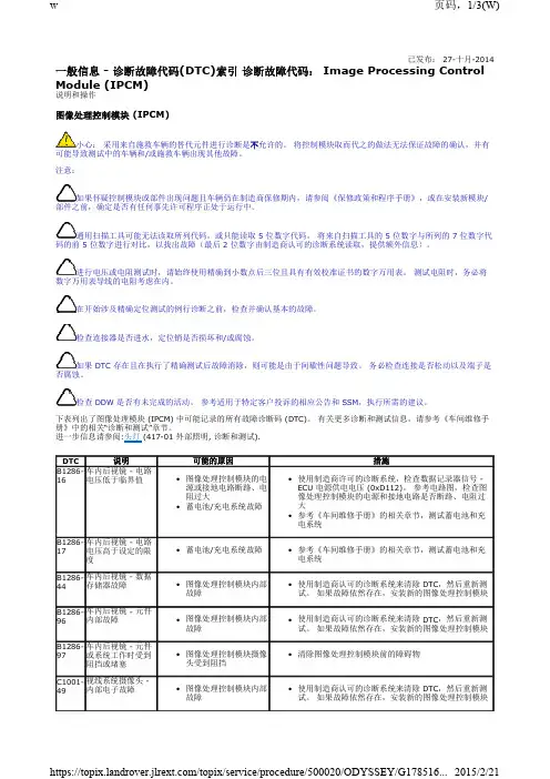
已发布: 27-十月-2014一般信息 - 诊断故障代码(DTC)索引 诊断故障代码: Image Processing Control Module (IPCM)说明和操作图像处理控制模块(IPCM)小心: 采用来自施救车辆的替代元件进行诊断是不允许的。
将控制模块取而代之的做法无法保证故障的确认,并有可能导致测试中的车辆和/或施救车辆出现其他故障。
注意:如果怀疑控制模块或部件出现问题且车辆仍在制造商保修期内,请参阅《保修政策和程序手册》,或在安装新模块/部件之前,确定是否有任何事先许可程序正处于运行中。
通用扫描工具可能无法读取所列代码,或只能读取 5 位数字代码。
将来自扫描工具的 5 位数字与所列的 7 位数字代码的前 5 位数字进行对比,以找出故障(最后 2位数字由制造商认可的诊断系统读取,提供额外信息)。
进行电压或电阻测试时,请始终使用精确到小数点后三位且具有有效校准证书的数字万用表。
测试电阻时,务必将数字万用表导线的电阻考虑在内。
在开始涉及精确定位测试的例行诊断之前,检查并确认基本的故障。
检查连接器是否进水,定位销是否损坏和/或腐蚀。
如果 DTC 存在且在执行了精确测试后故障消除,则可能是由于间歇性问题导致。
务必检查连接是否松动以及端子是否腐蚀。
检查 DDW 是否有未完成的活动。
参考适用于特定客户投诉的相应公告和 SSM ,执行所需的建议。
下表列出了图像处理模块 (IPCM) 中可能记录的所有故障诊断码 (DTC)。
有关更多诊断和测试信息,请参考《车间维修手册》中的相关“诊断和测试”章节。
进一步信息请参阅:头灯 (417-01 外部照明, 诊断和测试). DTC说明可能的原因措施B1286-16车内后视镜 - 电路电压低于临界值图像处理控制模块的电源或接地电路断路、电阻过大•蓄电池/充电系统故障•使用制造商许可的诊断系统,检查数据记录器信号 -ECU 电源供电电压 (0xD112)。
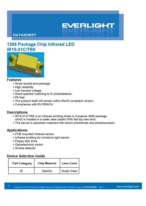
1 1206 Package Chip Infrared LED IR15-21C/TR8Features․Small double-end package ․High reliability․Low forward voltage․Good spectral matching to Si photodetector ․Pb free․The product itself will remain within RoHS compliant version. ․Compliance with EU REACHDescriptions․IR15-21C/TR8 is an infrared emitting diode in miniature SMD package which is molded in a water clear plastic With flat top view lens.․The device is spectrally matched with silicon photodiode and phototransistor.Applications․PCB mounted infrared sensor․Infrared emitting for miniature light barrier ․Floppy disk drive․Optoelectronic switch ․Smoke detector2Package DimensionsNotes: 1.All dimensions are in millimeters2.Tolerances unless dimensions ±0.1mm3.Suggested pad dimension is just for reference onlyPlease modify the pad dimension based on individual need3Notes: *1: Soldering time ≦5 seconds.45Typical Electro-Optical Characteristics Curves6 Precautions For Use1. Over-current-proofCustomer must apply resistors for protection, otherwise slight voltage shift will cause big current change (Burn out will happen). 2. Storage2.1 Do not open moisture proof bag before the products are ready to use.2.2 Before opening the package, the LEDs should be kept at 10℃~30℃ and 90%RH or less. 2.3 The LEDs suggested be used within one year.2.4 After opening the package, the devices must be stored at 10°C~30°C and 60%RH, and usedwithin 168 hours (floor life). If unused LEDs remain, it should be stored in moisture proof packages.2.5 If the moisture absorbent material (desiccant material) has faded or unopened bag hasexceeded the shelf life or devices (out of bag) have exceeded the floor life, baking treatment is required.2.6 If baking is required, refer to IPC/JEDEC J-STD-033 for bake procedure or recommend the following conditions:96 hours at 60°C ± 5°C and < 5 % RH (reeled/tubed/loose units) 3. Soldering Condition3.1 Pb-free solder temperature profile3.2 Reflow soldering should not be done more than two times. 3.3 When soldering, do not put stress on the LEDs during heating. 3.4 After soldering, do not warp the circuit board.7 4.Soldering IronEach terminal is to go to the tip of soldering iron temperature less than 350℃ for 3 seconds within once in less than the soldering iron capacity 25W. Leave two seconds and more intervals, and do soldering of each terminal. Be careful because the damage of the product is often started at the time of the hand solder. 5.RepairingRepair should not be done after the LEDs have been soldered. When repairing isunavoidable, a double-head soldering iron should be used (as below figure). It should be confirmed8Note : The tolerances unless mentioned are ±0.1mm, Unit: mm9 Label Form SpecificationCPN: Customer’s Production Number P/N : Production Number LOT No: Lot Number QTY: Packing Quantity HUE: Peak Wavelength CAT: RanksREF: Reference MSL-X: MSL LevelMade In: Manufacture placeNotes1. Above specification may be changed without notice. EVERLIGHT will reserve authority on material change for above specification.2. The graphs shown in this datasheet are representing typical data only and do not show guaranteed values.3. When using this product, please observe the absolute maximum ratings and the instructionsforuse outlined in these specification sheets. EVERLIGHT assumes no responsibility for any damage resulting from use of the product which does not comply with the absolute maximum ratings and the instructions included in these specification sheets.4. These specification sheets include materials protected under copyright of EVERLIGHT. Reproduction in any form is prohibited without the specific consent of EVERLIGHT.5. This product is not intended to be used for military, aircraft, automotive, medical, life sustaining or life saving applications or any other application which can result in human injury or death.Please contact authorized Everlight sales agent for special application request.。
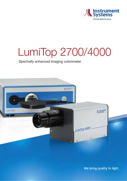
LumiTop 2700/4000 Spectrally enhanced imaging colorimeter\\ L ab specs meet production speedThe LumiTop 2700/4000 combines the accuracy of Instrument Systems’ well-known spectroradiometers CAS 140CT/D with the obvious advantages of imaging colorimetry. Principle: Fast and accurate With the help of a polarization insensitive, three-way beam splitter, the LumiTop 2700/4000 mergesan RGB CCD/CMOS camera anda flicker diode with the high-end spectroradiometer of the CAS series. This innovative design allows for simultaneous measurements of all components, which may result in significant time-savings.At the same time, the extremely accurate spectral information of the spectroradiometer measurement is used as reference for the camera measurement. This guarantees spectroradiometric accuracy across the whole 2D image.As a result, the LumiTop 2700/4000 not only performs fast 2D measurements with unprecedented accuracy but also offers all the advantages of classical imaging colorimetry. Perfect for productionBecause of this combination, theLumiTop 2700/4000 is perfectfor use in display productionlines or quality control, where thebenefits and capabilities of both,the accurate spot measurement ofspectroradiometers and the lateralresolution of camera measurementsare highly valued.All-in-one solutionMany different test applications cannow be organized in a single teststation:y M easurement of luminance andcolory E valuation of color and luminanceuniformity or Mura effectsy C ontrast measurementy A nalysis of white balance or colorgamuty F licker and luminance modulationmeasurementy A nalysis of the acquired spectraEasy to integrate intoproduction linesThe LumiTop 2700/4000 isintegrated in Instrument Systems’comprehensive new software…LumiSuite”, which comes witha user-friendly GUI for laboratoryapplications and a powerfulsoftware development kit for easyimplementation into any productionline. The spectra measured asreference for the camera can beanalyzed in more detail usingInstrument Systems’ well-knownsoftware SpecWin Pro.Independent of displaytechnologyDue to the high absolute accuracyof the CAS spectroradiometer thatis used as reference during eachmeasurement, the performanceof the solution is excellent for anydisplay technology (or any otherhomogeneous samples). Moreoverno golden sample or user calibrationsare needed. This makes the solutionparticularly favorable when OLEDs orother narrow-banded light sourceshave to be investigated where classicalimaging colorimeters based on XYZfilter technologies reach their limits.ModularityThe LumiTop 2700/4000 is designedas a modular accessory to thespectroradiometers CAS 140CT or D.Thus the same spectroradiometerscan also be used with the telescopicoptics TOP 150 or TOP 200 or viceversa.1)Inclusive lens and fiber exit.2)Without CAS, with mode mixer.3)E xternal neutral density filters on the lens (OD 0.3/0.6/0.9) are available for increasingthe upper measurement limit or measuring modulated light sources.4)L ower measurement limit based on a signal to noise ratio of 10:1 for maximumexposure time (60 seconds LumiTop 2700 / 10 seconds LumiTop 4000). Uppermeasurement limit based on a signal level < 80 % for a white (non-modulated) LED light source using for minimum exposure time (1 ms LumiTop 2700 / 27 µs LumiTop 4000).5)T ypical value for maximum deviation over the FOV relative to the CAS spot;calculated for an image with 16 pixels (LumiTop 2700) / 21 pixels (LumiTop 4000) cropped at each edge and 10 by 10 pixels (LumiTop 2700) / 13 by 13 pixels(LumiTop 4000) binning (34 averages) immediately after calibration with reference used for flat-field correction.6)2σ of repeated measurements of one instrument (white LED, L ≈ 100 cd/m2,autoexposure).7)R NU (response non-uniformity) is defined as 99.7 % percentile of the deviationof the mean image value; calculated for an image with 16 pixels (LumiTop 2700) /21 pixels (LumiTop 4000) cropped at each edge and 10 by 10 pixels (LumiTop 2700) /13 by 13 pixels (LumiTop 4000) binning (34 averages) immediately after calibrationwith reference used for flat-field correction.8)T ime between beginning of two subsequent measurements using the SDK;determined with a camera exposure time of 20 ms and CAS exposure time of200 ms for a white LED (L ≈ 500 cd/m2). Depends mainly on PC processingcapability.9)L ower measurement limit based on a signal to noise ratio of 10:1 for maximum exposuretime of 65 s. Upper measurement limit based on a signal level < 80 % for a white (non-modulated) LED light source using an optical density filter OD4 and minimum exposure time (10 ms CAS 140CT / 4 ms CAS 140D). Values valid for CAS 140CT with 100 µm and CAS 140D with 250 µm slit width.10)I mmediately after calibration relative to calibration standard.11)I mmediately after calibration.12)M aximum deviation from average of repeated CAS measurements with a linearpolarized light source and varying polarization angle.13)L ≈ 150 cd/m2, 30 Hz, 10 % sine wave.14)2σ of repeated measurements of one instrument.15)Distance between DUT and front plate of LumiTop.\\Technical specificationsWe bring quality to light.Instrument Systems GmbH Kastenbauerstr. 281677 Munich, Germany ph: +49 (0)89 45 49 43-58 fax: +49 (0)89 45 49 43-11 info@ b _L u m i T o p _e n _V 1.3Instrument Systems is continually working on the further development of its products. Technical changes, errors and misprints do not justify claims for damages. For all other purposes, our Terms and Conditions of Business shall be applicable.。
2015年IF(国际工业设计论坛)学生设计奖评选出了一批优秀的获奖作品,这些设计作品涵盖了从工业设计到产品设计等多个领域,展现了当代学生设计师的创新思维和设计能力。
本文将对2015年IF学生设计奖的获奖作品进行介绍,带领读者一窥这些优秀设计作品的精彩之处。
一、设计作品名称:智能家居控制器获奖等级:金奖设计团队:XXX大学设计学院设计理念:该智能家居控制器采用了人性化、智能化的设计理念,通过手机App远程控制家中的灯光、空调和安防系统,使用户能够随时随地轻松管理家居设备。
该控制器还具有自动学习功能,能够根据用户的习惯自动调节家居设备,提升用户的居家体验。
二、设计作品名称:可折叠自行车获奖等级:银奖设计团队:XXX大学交通工程学院设计理念:该可折叠自行车结合了高强度材料与创新的折叠结构,使自行车在保证牢固性的同时能够轻便易携带。
设计团队注重用户体验,通过人性化设计,让用户可以在城市间便捷地使用自行车,同时也减少了对环境的污染。
三、设计作品名称:多功能办公桌获奖等级:铜奖设计团队:XXX大学建筑设计学院设计理念:该多功能办公桌融合了书架、显示器支架和充电插座等功能于一体,满足了现代办公人员对办公桌多功能的需求。
设计团队在材料选择和结构设计上精益求精,使办公桌外观简约大方,功能完善。
四、设计作品名称:儿童座椅获奖等级:优秀奖设计团队:XXX艺术设计学院设计理念:该儿童座椅在材料选择上注重环保,采用了可降解材料进行制造,符合现代家长对儿童产品的环保需求。
设计团队还对座椅的外观进行了可爱温馨的设计,吸引了孩子的注意,增强了使用体验。
五、设计作品名称:智能健身手环获奖等级:优秀奖设计团队:XXX大学电子工程学院设计理念:该智能健身手环集成了心率监测、步数统计、睡眠监测等多种功能,通过手机App实时同步数据,为使用者提供全面的健康数据分析。
设计团队注重产品的舒适性和便携性,通过精心的材料选择和人体工程学设计,使手环佩戴舒适,便于随身携带。
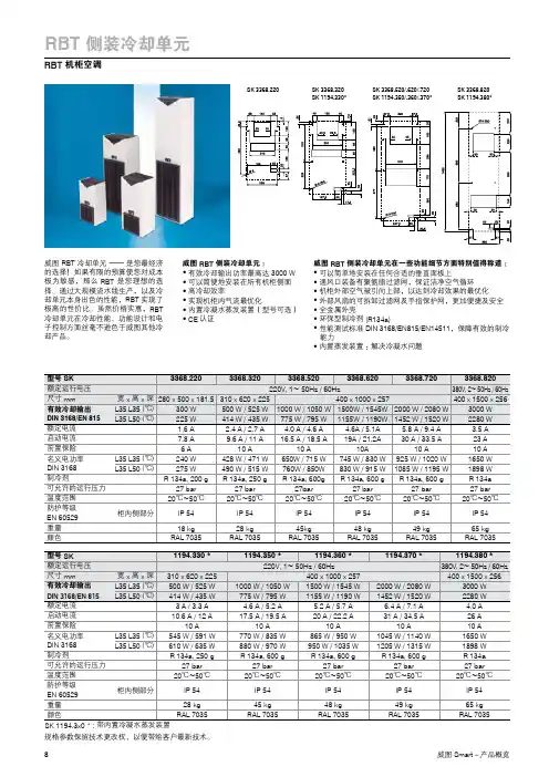
RBT 侧装冷却单元RBT 机柜空调威图 RBT 冷却单元 —— 是您最经济的选择!如果有限的预算使您对成本极为敏感,那么 RBT 是您理想的选择。
通过大规模流水线生产,以及冷却单元本身出色的性能,RBT 实现了极高的性价比。
虽然价格实惠,RBT 冷却单元在冷却性能、功能设计和电子控制方面丝毫不逊色于威图其他冷却产品。
威图 RBT 侧装冷却单元:● 有效冷却输出功率最高达 3000 W ● 可以简便地安装在所有机柜侧面● 高冷却效率● 实现机柜内气流最优化● 内置冷凝水蒸发装置(型号可选)● CE 认证威图 RBT 侧装冷却单元在一些功能细节方面特别值得称道:●可以简单地安装在任何合适的垂直面板上● 通风口装备有聚氨脂过滤网,保证洁净空气循环● 机柜外部空气被引向上部,以达到冷却效果的最优化● 外部风扇的可拆卸过滤网及手指保护网,更加便捷及安全● 全金属外壳● 环保型制冷剂 (R134a)● 性能测试标准 DIN 3168/EN815/EN14511,保障有效的制冷能力● 内置蒸发装置:解决冷凝水问题规格参数保留技术更改权,以便带给客户最新技术。
SK 3368.220SK 3368.320SK 1194.330*SK 3368.820SK 1194.380*SK 3368.520/.620/.720SK 1194.350/.360/.370*Compact 冷却单元威图Compact 机柜空调系列: ● 极高的性价比● 外观为RAL7035颜色,与柜体保持一致● 超薄设计,安装方式可以选择外挂式和嵌入式两种● 宽泛电源范围,单向电源和三相电源型号均可选择● 控制器为数码显示及按键操作,温度显示和高低温等报警显示● 显示器和控制器一体化,无电控板,更耐恶劣的工作环境● 所有型号都通过第三方性能测试认证,符合DIN 3168/EN815/EN14511标准,制冷能力及性能安全可靠● 环保型制冷剂 (R134a)● 标配中英文使用说明书● CE 认证● 常备库存,快速发货● 可选配置:内置蒸发装置,解决冷凝水问题(型号见下表最后一项)Compact 机柜空调SK337022XSK337022XSK337032XSK337032XSK337072XSK337072XSK337042X SK337042X SK337052X SK337052X SK337062XSK337062X规格参数保留技术更改权,以便带给客户最新技术。
SUNNY TRIPOWER15000TL / 20000TL / 25000TLS T P 15000T L -30 / S T P 20000T L -30 / S T P 25000T L -30Efficient• Maximum efficiency of 98.4%• Yield increase without installation effort due to integrated shade management SMA ShadeFixFlexible• DC input voltage of up to 1000 V • Multistring capability for optimum system design • Optional displayInnovative• Cutting-edge grid management func-tions with Integrated Plant Control • Reactive power available 24/7 (Q on Demand 24/7)Safe• DC surge arrester (SPD type II) can be integratedSUNNY TRIPOWER 15000TL / 20000TL / 25000TLThe versatile specialist for large-scale commercial plants and solar power plantsThe Sunny Tripower is the ideal inverter for large-scale commercial and industrial plants. Not only does it deliver extraordinary high yields with an efficiency of 98.4%, but it also offers enormous design flexibility and compatibility with many PV modules thanks to its multistring capabilities and wide input voltage range.The future is now: the Sunny Tripower comes with cutting-edge grid management functions such as Integrated Plant Control, which allows the inverter to regulate reactive power at the point of common coupling. Separate con-trollers are no longer needed, lowering system costs. Another new feature—reactive power provision on demand (Q on Demand 24/7).Intelligent service with SMA Smart ConnectedSMA SMART CONNECTEDThe integrated service for ease and comfort SMA Smart Connected* is the free monitoring of the inverter via the SMA Sunny Portal. If there is an inverter fault, SMA proactively informs the PV system operator and the installer. This saves valuable working time and costs.With SMA Smart Connected, the installer benefits from rapid diagnoses by SMA. They can thus quickly rectify the fault and score points with the customer thanks to the attraction of additional services.* Details: see document “Description of Services – SMA SMART CONNECTED”AccessoryRS485 interface DM-485CB-10DC surge arrester Typ II, inputs A and B DCSPD KIT3-10Power Control Module PWCMOD-10Multifunction relay MFR01-10● Standard features ○ Optional features — Not available Data at nominal conditions Status: 03/2020Technical DataSunny Tripower15000TL Sunny Tripower 20000TL Sunny Tripower 25000TLInput (DC)Max. generator power 27000 Wp 36000 Wp 45000 Wp DC rated power 15330 W 20440 W 25550 W Max. input voltage1000 V1000 V 1000 VMPP voltage range / rated input voltage 240 V to 800 V / 600 V 320 V to 800 V / 600 V 390 V to 800 V / 600 VMin. input voltage / start input voltage 150 V / 188 V 150 V / 188 V 150 V / 188 V Max. input current input A / input B33 A / 33 A 33 A / 33 A 33 A / 33 A Number of independent MPP inputs / strings per MPP input 2 / A:3; B:3 2 / A:3; B:3 2 / A:3; B:3Output (AC)Rated power (at 230 V, 50 Hz)15000 W 20000 W 25000 WMax. AC apparent power 15000 VA20000 VA 25000 VAAC nominal voltage 3 / N / PE; 220 V / 380 V 3 / N / PE; 230 V / 400 V 3 / N / PE; 240 V / 415 VAC voltage range180 V to 280 V AC grid frequency / range50 Hz / 44 Hz to 55 Hz 60 Hz / 54 Hz to 65 HzRated power frequency / rated grid voltage 50 Hz / 230 VMax. output current / Rated output current29 A / 21.7 A 29 A / 29 A 36.2 A / 36.2 APower factor at rated power / Adjustable displacement power factor 1 / 0 overexcited to 0 underexcitedTHD≤ 3%Feed-in phases / connection phases 3 / 3Effi ciency Max. effi ciency / European Effi ciency 98.4% / 98.0%98.4% / 98.0%98.3% / 98.1%Protective devicesDC-side disconnection device●Ground fault monitoring / grid monitoring ● / ●DC surge arrester (Type II) can be integrated○DC reverse polarity protection / AC short-circuit current capability / galvanically isolated ● / ● / —All-pole sensitive residual-current monitoring unit●Protection class (according to IEC 62109-1) / overvoltage category (according to IEC 62109-1)I / AC: III; DC: IIGeneral dataDimensions (W / H / D)661 / 682 / 264 mm (26.0 / 26.9 / 10.4 inch)Weight61 kg (134.48 lb)Operating temperature range −25 °C to +60 °C (−13 °F to +140 °F)Noise emission (typical)51 dB(A)Self-consumption (at night) 1 WTopology / cooling conceptTransformerless / OpticoolDegree of protection (as per IEC 60529)IP65Climatic category (according to IEC 60721-3-4)4K4H Maximum permissible value for relative humidity (non-condensing)100%Features / function / Accessories DC connection / AC connection SUNCLIX / spring-cage terminalDisplay○Interface: RS485, Speedwire/Webconnect○ / ●Data interface: SMA Modbus / SunSpec Modbus ● / ●Multifunction relay / Power Control Module○ / ○Shade management SMA ShadeFix / Integrated Plant Control / Q on Demand 24/7● / ● / ●Off-Grid capable / SMA Fuel Save Controller compatible ● / ●Guarantee: 5 / 10 / 15 / 20 years ● / ○ / ○ / ○Certifi cates and permits (more available on request)* D oes not apply to all national appendices of EN 50438AS 4777, BDEW 2008, C10/11, CE, CEI 0-16, CEI 0-21, CNS 15382, CNS 15426, DEWA 2.0, DK1, DK2, EN 50549-1, EN 50549-2, G99/1, EN 50438:2013*, IEC 60068-2-x, IEC 61727, IEC 62109-1/2, IEC 62116, IS 16221-1/2, IS 16169, MEA 2013, NBR 16149, NEN EN 50438, NRS 097-2-1, PEA 2013, NTS, PPC, RD 1699/413, RD 661/2007, Res. n°7:2013, RfG compliant,SI4777, TOR generator, UTE C15-712-1, VDE 0126-1-1, VDE-AR-N 4105, VDE-AR-N 4110,VFR 2014Type designationSTP 15000TL-30STP 20000TL-30STP 25000TL-30SMA Solar Technology S T P 15-25T L -30-D S -e n -40 S M A a n d S u n n y T r i p o w e r a r e r e g i s t e r e d t r a d e m a r k s o f S M A S o l a r T e c h n o l o g y A G . S U N C L I X i s a r e g i s t e r e d t r a d e m a r k o f P H O E N I X C O N T A C T G m b H & C o . K G . P r i n t e d o n F S C p a p e r . A l l p r o d u c t s a n d s e r v i c e s d e s c r i b e d a n d a l l t e c h n i c a l d a t a a r e s u b j e c t t o c h a n g e , e v e n f o r r e a s o n s o f c o u n t r y -s p e c i f i c d e v i a t i o n s , a t a n y t i m e w i t h o u t n o t i c e . S M A a s s u m e s n o l i a b i l i t y f o r t y p o g r a p h i c a l a n d o t h e r e r r o r s . F o r t h e l a t e s t i n f o r m a t i o n , p l e a s e v i s i t w w w .S M A -S o l a r .c o m .Professional PV system monitoring, management and data display。
STPTIC-15L2C4WLCSP 3 solder barsPTICRF1Features•High power capability •5:1 tuning range •High linearity (48x)•High quality factor (Q)•Low leakage current•Compatible with high voltage control IC (STHVDAC series)•RF tunable passive implementation in mobile phones to optimize antenna radiated performance•Available in wafer level chip scale package:–WLCSP package 0.75 x 0.72 x 0.32 mm •ECOPACK ®2 compliant componentApplications•Cellular antenna open loop tunable matching network in multi-band GSM/WCDMA/LTE mobile phone •Open loop tunable RF filtersDescriptionThe ST integrated tunable capacitor offers excellent RF performance, low power consumption and high linearity required in adaptive RF tuning applications. Thefundamental building block of PTIC is a tunable material called Parascan™, which is a version of barium strontium titanate (BST) developed by Paratek microwave.BST capacitors are tunable capacitors intended for use in mobile phone application and dedicated to RF tunable applications. These tunable capacitors are controlled through an extended bias voltage ranging from 1 to 24 V. The implementation of BST tunable capacitor in mobile phones enables significant improvement in terms of radiated performance making the performance almost insensitive to the external environment.Parascan is a trademark of Paratek Microwave Inc.Parascan™ tunable integrated capacitorSTPTIC-15C4DatasheetSTPTIC-15C4STPTIC-15C4 characteristics 1STPTIC-15C4 characteristicsTable 1. Absolute maximum ratings (limiting values)1.Class 1B defined as passing 500 V, but fails after exposure to 1000V ESD pulse.Table 2. Recommended operating conditionsTable 3. Representative performance (T amb = 25 °C otherwise specified)1.Measured at low frequency2.F 1 = 894 MHz, F 2 = 849 MHz, P 1 = +25 dBm, P 2 = +25 dBm, 2f 1 - f 2 = 939 MHz3.IP3 and harmonics are measured in the shunt configuration in a 50 Ω environment4.850 MHz, P IN = +34 dBm5.One or both of RF IN and RF OUT must be connected to DC ground, using the HVDAC turbo mode. Transition time for tunerbetween Cmin. to 90% of Cmax. or Cmax. to 90% of Cmin. include MIPI order work time (trig with last MIPI CLK).1.1RF measurementsFigure 3. Harmonic power versus bias voltage (shunt)Figure 4. Harmonic power versus bias voltage (series)STPTIC-15C4RF measurementsFigure 5.Third order intercept point (IP3)STPTIC-15C4RF measurements2Package informationIn order to meet environmental requirements, ST offers these devices in different grades of ECOPACK®packages, depending on their level of environmental compliance. ECOPACK® specifications, grade definitionsand product status are available at: . ECOPACK® is an ST trademark.2.1WLCSP 3 solder bars package informationFigure 8. WLCSP 3 solder bars package outlineBottom view(balls up)Top view(balls down)Side view Table 4. WLCSP 3 solder bars package dimensionsSTPTIC-15C4Package informationSTPTIC-15C4WLCSP 3 solder bars package informationFigure 9. Recommended PCB land pattern for WLCSP 3 solder bars package Copper pads Solder stencilTable 5. Dimensions2.2Packing informationFigure 10. Tape and reel outlineTable 6. Pocket dimensionsFigure 11. MarkingTop view (balls down)Bottom view (balls up)STPTIC-15C4Packing informationSTPTIC-15C4Reflow profileTable 7. Pinout description1.When connected in shunt, please connect RF2 (B2 ball) to GND2.3Reflow profileFigure 12. ST ECOPACK® recommended soldering reflow profile for PCB mountingNote:Minimize air convection currents in the reflow oven to avoid component movement.Table 8. Recommended values for soldering reflow3Evaluation boardFigure 14.Layer 1 and layer 4Figure 15. Layer 2 and layer 3RFinRFoutDC BiasSerie RFinRFoutDC BiasSHUNTSTPTIC-15C4Evaluation board4Ordering informationFigure 16. Ordering information schemeST PTIC - 15 L 2 C4ST MicroelectronicsPTICParascan™ tunableIntegrated capacitorCapacitorvalueLinearityF: Standard (x24)G: Standard (x24)L: High (x48)PackageTuning15 = 1.5 pF27 = 2.7 pF33 = 3.3 pF39 = 3.9 pF47 = 4.7 pF56 = 5.6 pF68 = 6.8 pF82 = 8.2 pFM6 : QFNC5 : WLCSP400 µm coating1 = 4/1 tuning2 = 5/1 tuningProduct familyManufacturer-C4 : WLCSP3 solder barsTable 9. Ordering informationOrdering informationRevision historyTable 10. Document revision historyIMPORTANT NOTICE – PLEASE READ CAREFULLYSTMicroelectronics NV and its subsidiaries (“ST”) reserve the right to make changes, corrections, enhancements, modifications, and improvements to ST products and/or to this document at any time without notice. Purchasers should obtain the latest relevant information on ST products before placing orders. ST products are sold pursuant to ST’s terms and conditions of sale in place at the time of order acknowledgement.Purchasers are solely responsible for the choice, selection, and use of ST products and ST assumes no liability for application assistance or the design of Purchasers’ products.No license, express or implied, to any intellectual property right is granted by ST herein.Resale of ST products with provisions different from the information set forth herein shall void any warranty granted by ST for such product.ST and the ST logo are trademarks of ST. All other product or service names are the property of their respective owners.Information in this document supersedes and replaces information previously supplied in any prior versions of this document.© 2018 STMicroelectronics – All rights reservedSTPTIC-15L2C4。