数字频率合成器的外文翻译
- 格式:doc
- 大小:104.00 KB
- 文档页数:19
频率合成技术DDS介绍—AD系列常用的频率合成技术(FS, Frequency Synthesis)有模拟锁相环、数字锁相环、小数分频锁相环(fractional-N PLL Synthesis)等,直接数字合成(Direct Digital Synthesis-DDS)是近年来新的FS技术。
1.频率合成技术的发展现状由于直接数字频率合成器采用全数字方式实现频率合成,它直接对参考正弦时钟进行抽样和数字化,然后通过数字计算技术进行频率合成。
因此,它具有其它频率合成方法无法比拟的优点,频率转换速度快、频率分辨率高、输出相位连续、可编程、全数字化易于集成、体积小、功耗低等。
直接数字频率合成器在现代电子器件、通信技术、医学成像、无线、PCS/PCN 系统、雷达、卫星通信等众多领域得到了各方应用。
2.DDS与模拟PLL性能比较(1)输出分辨率小只要相位累加器的位宽足够大,参考时钟频率足够小,则分辨率可以很小:AD9850(参考时钟频率fc=125MHz)的相位累加器为32位,分辨率0.03Hz;AD9830(参考时钟频率fc=50MHz)的相位累加器为32位,分辨率0.012Hz;AD9852(参考时钟频率fc=300MHz)的相位累加器为48位,分辨率1*10-6Hz。
相反,模拟锁相环的合成器的分辨率为1KHz,它缺乏数字信号处理的固有特性。
(2)输出频率变换时间小一个模拟锁相环的频率变换时间主要是它的反馈环处理时间和压控振荡器的响应时间,通常大于1ms。
整片DDS合成器的频率变换时间主要是DDS的数字处理延迟,通常为几十个ns(AD9850最小43ns)。
(3)调频范围大一个负反馈环的带宽输出参考频率决定了模拟锁相环的稳定的调频范围;整片的DDS合成器是不受稳定性的影响的,在整个Nyquist频率范围内是可调的。
(4)相位噪声DDS优于PLL的最大优势就是它的相位噪声。
由于数字正弦信号的相位与时间成线形关系,整片的DDS输出的相位噪声比它的参考时钟源的相位噪声小。
直接数字频率合成器原理直接数字频率合成器(Direct Digital Frequency Synthesizer,简称DDFS)是一种用于产生高精度、稳定的频率信号的电子设备。
它通过数字电路实现频率的直接合成,可以产生任意频率的信号,并且具有快速调谐、高精度以及低相位噪声等优点。
本文将介绍DDFS的工作原理及其在实际应用中的重要性。
一、工作原理DDFS的核心组成部分是相位累加器(Phase Accumulator)、频率控制字(Frequency Control Word)和查表器(Look-up Table)。
相位累加器通过不断累加频率控制字的值,从而产生一个随时间线性增加的相位值。
查表器中存储了正弦波的采样值,通过查表器可以根据相位值得到对应的正弦波样本。
最后,通过数模转换器将数字信号转换为模拟信号输出。
具体来说,DDFS的工作原理如下:1. 频率控制字:频率控制字是一个二进制数,用于控制相位累加器的累加速度。
频率控制字的大小决定了相位累加器每个时钟周期累加的值,从而决定了输出信号的频率。
2. 相位累加器:相位累加器是一个寄存器,用于存储当前的相位值。
相位累加器的值会在每个时钟周期根据频率控制字的大小进行累加。
相位累加器的位数决定了相位的分辨率,位数越多,相位分辨率越高,输出信号的频率分辨率也越高。
3. 查表器:查表器中存储了一个周期内的正弦波样本值(或余弦波样本值),通过查表器可以根据相位累加器的值得到对应的正弦波样本值。
4. 数模转换器:数模转换器将数字信号转换为模拟信号输出。
通常使用的是高速数模转换器,能够将数字信号以高速率转换为模拟信号输出。
二、应用领域DDFS在许多领域中都有广泛的应用,其中包括通信、雷达、测量、音频处理等。
1. 通信领域:在通信系统中,DDFS被广泛应用于频率合成器、频率调制器和频率解调器等模块中。
通过DDFS可以快速、精确地合成所需的信号频率,实现高速数据传输和频谱分析等功能。
直接数字频率合成芯片-概述说明以及解释1.引言1.1 概述在概述部分,我们将介绍直接数字频率合成芯片的基本概念和作用。
直接数字频率合成芯片(Direct Digital Frequency Synthesizer,DDS)是一种用于产生不同频率信号的集成电路。
基于数字信号处理技术,DDS 芯片可以精确地生成各种频率和相位的信号。
相较于传统的模拟频率合成方法,DDS芯片具有更高的稳定性、精度和灵活性。
DDS芯片的工作原理基于数学算法和数字信号处理技术。
通过将数字信息转换为模拟信号输出,DDS芯片可以产生具有精确频率和相位的信号波形。
其核心部件包括相位积累器、数字控制振荡器和数模转换器。
相位积累器负责积累相位信息,数字控制振荡器则通过控制相位积累器的速率来实现不同频率信号的生成。
最后,数模转换器将数字信号转换为模拟信号输出。
直接数字频率合成芯片具有广泛的应用领域。
在通信系统中,DDS芯片被广泛应用于频率合成器、频率调制器、信号发生器等设备中。
其高精度和频率可调性使其成为无线通信、雷达、医学成像以及科学研究等领域的重要组成部分。
此外,DDS芯片还可以用于频率跟踪和频率锁定的系统中,提供更好的稳定性和精度。
总而言之,直接数字频率合成芯片通过数字信号处理技术实现高稳定性、精确性和灵活性的频率合成。
它在通信系统、科学研究和医学成像等领域具有广泛的应用前景。
随着科技的不断进步,我们可以期待直接数字频率合成芯片在未来的发展中发挥更重要的作用。
1.2 文章结构本文的结构主要分为引言、正文和结论三个部分。
在引言部分,我们将概述直接数字频率合成芯片,解释其基本原理和应用领域,并阐述本文的目的。
接着,在正文部分,首先我们将详细介绍直接数字频率合成芯片的原理,包括其工作原理、数字信号处理流程以及关键技术。
其次,我们将探讨直接数字频率合成芯片的应用领域,包括通信、雷达、电子音乐等方面,并论述其在各个领域中的优势和局限性。
最后,在结论部分,我们将总结直接数字频率合成芯片的优势,包括其高精度、灵活性强以及节省硬件开销等方面,并展望其未来的发展方向,包括对数字信号处理算法的优化、功耗降低以及更广泛的应用领域等方面的潜力。
DDS(DirectDigitalSynthesizer)直接数字式频率合成器1. 什么叫DDS直接数字式频率器DDS(Direct Digital Synthesizer),实际上是⼀种分频器:通过编程频率控制字来分频系统(SYSM CLOCK)以产⽣所需要的频率。
DDS 有两个突出的特点,⼀⽅⾯,DDS⼯作在数字域,⼀旦更新频率控制字,输出的频率就相应改变,其跳频速率⾼;另⼀⽅⾯,由于频率控制字的宽度宽(48bit 或者更⾼),频率分辨率⾼。
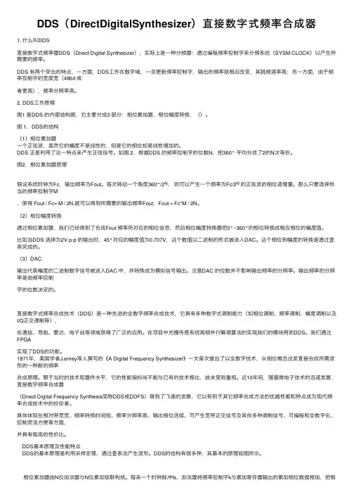
2. DDS⼯作原理图1 是DDS 的内部结构图,它主要分成3 部分:相位累加器,相位幅度转换,()。
图 1,DDS的结构(1)相位累加器⼀个正弦波,虽然它的幅度不是线性的,但是它的相位却是线性增加的。
DDS 正是利⽤了这⼀特点来产⽣正弦信号。
如图 2,根据DDS 的频率控制字的位数N,把360° 平均分成了2的N次等份。
图2,相位累加器原理假设系统时钟为Fc,输出频率为Fout。
每次转动⼀个⾓度360°/2N,则可以产⽣⼀个频率为Fc/2N的正弦波的相位递增量。
那么只要选择恰当的频率控制字M,使得 Fout / Fc= M / 2N,就可以得到所需要的输出频率Fout,Fout = Fc*M / 2N。
(2)相位幅度转换通过相位累加器,我们已经得到了合成Fout 频率所对应的相位信息,然后相位幅度转换器把0°~360°的相位转换成相应相位的幅度值。
⽐如当DDS 选择为2V p-p 的输出时,45°对应的幅度值为0.707V,这个数值以⼆进制的形式被送⼊DAC。
这个相位到幅度的转换是通过查表完成的。
(3)DAC输出代表幅度的⼆进制数字信号被送⼊DAC 中,并转换成为模拟信号输出。
注意DAC 的位数并不影响输出频率的分辨率。
输出频率的分辨率是由频率控制字的位数决定的。
直接数字式频率合成技术(DDS)是⼀种先进的全数字频率合成技术,它具有多种数字式调制能⼒(如相位调制、频率调制、幅度调制以及I/Q正交调制等),在通信、导航、雷达、电⼦战等领域获得了⼴泛的应⽤。

数字频率合成器设计实例数字频率合成器设计实例数字频率合成器(Digital Frequency Synthesizer)是一种能够产生不同频率信号的设备。
它通过使用数字技术和数学算法来合成所需的频率,具有高精度和稳定性。
在本文中,我们将逐步介绍数字频率合成器的设计过程。
1. 设定所需频率范围:首先,确定所需合成的频率范围。
这取决于具体应用,例如音频处理、无线通信等。
假设我们的频率范围为1Hz到10kHz。
2. 确定采样率:采样率是指每秒钟对信号进行采样的次数。
根据香农抽样定理,采样率应大于信号最高频率的两倍。
在我们的例子中,最高频率为10kHz,因此选择采样率为至少20kHz。
3. 选择数字信号处理器(DSP):为了实现数字频率合成器,我们需要选择一种适合的DSP芯片。
DSP芯片能够高效地执行数字信号处理任务,例如信号生成和滤波。
选择一款性能强大且易于编程的DSP 芯片,以满足所需的合成要求。
4. 设计频率控制模块:频率控制模块是数字频率合成器的核心部分,用于生成所需频率的数字信号。
它通常由相位锁定环(PLL)和数字控制振荡器(NCO)组成。
a. 相位锁定环(PLL):PLL是一种控制系统,通过比较输入信号的相位和参考信号的相位差异来产生所需频率的输出信号。
通过调整参考信号的频率和相位,PLL可以实现精确的频率合成。
b. 数字控制振荡器(NCO):NCO是一种可编程振荡器,能够生成具有可变频率的数字信号。
通过调整输入的控制参数,NCO能够实现不同频率的信号合成。
5. 编程实现:根据DSP芯片的编程手册和软件开发工具,编写相应的代码实现频率控制模块。
通过配置PLL和NCO的参数,以及设置合适的参考信号,实现所需频率的合成。
6. 验证和调试:使用示波器或频谱分析仪等测试工具,验证合成的频率是否符合要求。
如果发现频率偏差或其他问题,可以通过调整PLL和NCO的参数来进行调试和校准。
7. 优化和改进:根据实际应用需求和反馈,对数字频率合成器进行优化和改进。
本科毕业设计(论文)外文翻译译文学生姓名:王惠院(系):电子工程学院仪器系专业班级:测控0701指导教师:刘选朝完成日期: 20 11 年 3 月 7 日咨询应用工程师- 33关于直接数字频率合成器的问题作者Eva Murphy]Colm Slattery]什么是直接数字频率合成器?直接数字频率合成器(DDS)是一种产生模拟波形(通常是正弦波)的仪器,这种仪器是生成一个数字形式的时变信号,然后执行数字到模拟的转换。
因为用一个DDS设备操作主要是数字形式,所以它可以提供输出频率之间的快速转换,较高的频率分辨率并且可以在一个宽频带上进行操作。
随着设计和工艺技术的进步,现在的DDS器件都非常小巧,在低功率下也可以工作。
为什么我们要使用直接数字频率合成器(DDS)?难道就没有其他产生频率的简单方法吗?能够准确地产生和控制各种频率和轮廓的波形的能力已成为一个通用于多个行业重要要求。
在通信系统中能否利用良好的杂散性提供低相位噪声可变频率的活跃来源,或仅产生用于工业或生物医学测试设备的应用的频率刺激,便利、简洁和低成本是重要的设计考虑因素。
频率产生的多种可能性对设计师来说是开放的,从锁相回路(PLL)——极高频率合成的基础技术,到以数模转换器(DAC)的动态编制程序输出来产生低频任意波形。
但是DDS技术迅速在解决频率(或波形)产生的通信和工业应用要求上得到接受,因为单芯片集成电路器件可以简单的产生可编程模拟输出波形,具有较高的分辨率和精度。
此外,在这两种工艺技术和设计的不断改进也使得成本和功耗较从前降低了许多。
例如,AD9833——基于DDS的可编程波形发生器(图1)在V的电压下工作工作具有25 MHz的时钟,消耗的最大功率为30毫瓦。
图1 单片波形发生器使用直接数字频率合成器(DDS)的主要优点有哪些?像AD9833 之类的DDS器件都可通过一个高速串行外设接口(SPI)进行编程,并且只需要一个外部时钟来生成简单的正弦波。
附录2:外文原文,译文Modulating Direct Digital Synthesizer In the pursuit of more complex phase continuous modulation techniques, the control of the output waveform becomes increasingly more difficult with analog circuitry. In these designs, using a non-linear digital design eliminates the need for circuit board adjustments over yield and temperature. A digital design that meets these goals is a Direct Digital Synthesizer DDS. A DDS system simply takes a constant reference clock input and divides it down a to a specified output frequency digitally quantized or sampled at the reference clock frequency. This form of frequency control makes DDS systems ideal for systems that require precise frequency sweeps such as radar chirps or fast frequency hoppers. With control of the frequency output derived from the digital input word, DDS systems can be used as a PLL allowing precise frequency changes phase continuously. As will be shown, DDS systems can also be designed to control the phase of the output carrier using a digital phase word input. With digital control over the carrier phase, a high spectral density phase modulated carrier can easily be generated.This article is intended to give the reader a basic understanding of a DDS design, and an understanding of the spurious output response. This article will also present a sample design running at 45MHz in a high speed field programmable gate array from QuickLogic.A basic DDS system consists of a numerically controlled oscillator (NCO) used to generate the output carrier wave, and a digital to analog converter (DAC) used to take the digital sinusoidal word from the NCO and generate a sampled analog carrier. Since the DAC output is sampled at the reference clock frequency, a wave form smoothing low pass filter is typically used to eliminate alias components. Figure 1 is a basic block diagram of a typical DDS system generation of the output carrier from the reference sample clock input is performed by the NCO. The basic components of the NCO are a phase accumulator and a sinusoidal ROM lookup table. An optional phase modulator can also be include in the NCO design. This phase modulator will add phase offset to the output of the phase accumulator just before the ROM lookup table. This will enhance the DDS system design by adding the capabilities to phase modulate the carrier output of the NCO. Figure 2 is a detailed block diagram of a typical NCO design showing the optional phase modulator.FIGURE 1: Typical DDS System.FIGURE 2: Typical NCO Design.To better understand the functions of the NCO design, first consider the basic NCO design which includes only a phase accumulator and a sinusoidal ROM lookup table. The function of these two blocks of the NCO design are best understood when compared to the graphical representation of Euler’s formula ej wt = cos( wt) + jsin( wt). T hegraphical representation of Euler’s formula, as shown in Figure 3, is a unit vector rotating around the center axis of the real and imaginary plane at a velocity of wrad/s. Plotting the imaginary component versus time projects a sine wave while plotting the real component versus time projects a cosine wave. The phase accumulator of the NCO is analogous, or could be considered, the generator of the angular velocity component wrad/s. The phase accumulator is loaded, synchronous to the reference sample clock, with an N bit frequency word.This frequency word is continuously accumulated with the last sampled phase value by an N bit adder. The output of the adder is sampled at the reference sample clock by an N bit register. When the accumulator reaches the N bit maximum value, the accumulator rolls over and continues. Plotting the sampled accumulator values versus time produces a saw tooth wave form as shown below in Figure 3. FIGURE 3 Euler’s Equation Represented GraphicallyThe sampled output of the phase accumulator is then used to address a ROM lookup table of sinusoidal magnitude values. This conversion of the sampled phase to a sinusoidal magnitude is analogous to the projection of the real or imaginary component in time. Since the number of bits used by the phase accumulator determines the granularity of the frequency adjustment steps, a typical phase accumulator size is 24 to 32 bits. Since the size of the sinusoidal ROMtable is directly proportional to the addressing range, not all 24 or 32 bits of the phase accumulator are used to address the ROM sinusoidal table. Only the upper Y bits of the phase accumulator are used to address the sinusoidal ROM table, where Y < N bits and Y is typically but not necessarily equal to D, and D is the number of output magnitude bits from the sinusoidal ROM table.Since an NCO outputs a carrier based on a digital representation of the phase and magnitude of the sinusoidal wave form, designers have complete control over frequency, phase, and even amplitude of the output carrier. By adding a phase port and a phase adder to the basic NCO design, the output carrier of the NCO can be M array phase modulated where M equals the number of phase port bits and where M is less than or equal to the Y number of bits used to address the sinusoidal ROM table. For system designs that require amplitude modulation such as QAM, a magnitude port can be added to adjust the sinusoidal ROM table output. Note that this port is not shown in Figure 2 and that this feature is not demonstrated in the sample QuickLogic FPGA design. Finally, frequency modulation is a given with the basic NCO design. The frequency port can directly adjust the carrier output frequency. Since frequency words are loaded into the DDS synchronous to the sample clock, frequency changes are phase continuous.Although DDS systems give the designer complete control ofcomplex modulation synthesis, the representation of sinusoidal phase and magnitude in a non-linear digital format introduces new design complexities. In sampling any continuous-time signal, one must consider the sampling theory and quantization error.To understand the effects of the sampling theory on a DDS system, it is best to look at the DDS synthesis processes in both the time and frequency domain. As stated above, the NCO generates a sinusoidal wave form by accumulating the phase at a specified rate and then uses the phase value to address a ROM table of sinusoidal amplitude values. Thus, the NCO is essentially taking a sinusoidal wave form and sampling it with the rising or falling edge of the NCO input reference sampling clock. Figure 4 shows the time and frequency domain of the NCO processing. Note that this representation does not assume quantization.Based on the loaded frequency word, the NCO produces a set of amplitude output values at a set period. The frequency domain representation of this sinusoid is an impulse function at the specified frequency. The NCO, however, outputs discrete digital samples of this sinusoid at the NCO reference clock rate. In the time domain, the NCO output is a function of the sampling clock edge strobes multiplied by the sinusoid wave form producing a train of impulses at the sinusoid amplitude. In the frequency domain, the sampling strobes of the reference clock produce a train of impulses at frequencies of K times theNCO clock frequency where K = ... - 1, 0, 1, 2 .... Since the sampling clock was multiplied by the sinusoid in the time domain, the frequency domain components of the sinusoid and the sampling clock need to be convolved to produce the frequency domain representation of the NCO output.The frequency domain results are the impulse function at the fundamental frequency of the sinusoid and the alias impulse functions occurring at K times the NCO clock frequency plus or minus the fundamental frequency. The fundamental and alias component occur at: K*Fclk - FoutK*Fclk + FoutWhere K = ... -1, 0 , 1, 2 ..... and K = 0 is the NCO sinusoid fundamental frequencyFout is the specified NCO sinusoid output frequencyFclk is the NCO reference clock frequencyFIGURE 4 NCO Output Representation Time and Frequency Domain The DAC of the DDS system takes the NCO output values and translates these values into analog voltages. Figure 4 shows the time and frequency domain representations of the DAC processing starting with the NCO output. The DAC output is a sample and hold circuit that takes the NCO digital amplitude words and converts the value into an analog voltage and holds the value for one sample clock period. The timedomain plot of the DAC processing is the convolution of the NCO sampled output values with a pulse of one sample clock period. The frequency domain plot of the sampling pulse is a sin(x)/x function with the first null at the sample clock frequency. Since the time domain was convolved, the frequency domain is multiplied. This multiplication dampens the NCO output with the sin(x)/x envelope. This attenuation at the DAC output can be calculated as follows and a sample output spectrum is shown in Figure 5:Atten(F) = 20log[(sin(pF/Fclk)/pF/Fclk)] Where F is the output frequency Fclk is the sample clock frequencyFIGURE 5: DAC Output Representation in Time and Frequency Domain Aside from the sampling theory, the quantization of the real values into digital form must also be considered in the performance analysis of a DDS system. The spurious response of a DDS system is primarily dictated by two quantization parameters. These parameters are the phase quantization by the phase accumulator and the magnitude quantization by the ROM sinusoidal table and the DAC.As mentioned above, only the upper Y bits of the phase accumulator are used to address the ROM lookup table. It should be noted, however, that using only the upper Y bits of the phase accumulator introduces a phase truncation. When a frequency word containing a non-zero value in the lower (N-Y-1:0) bits is loaded into the DDS system, the lowernon-zero bits will accumulate to the upper Y bits and cause a phase truncation. The frequency at which the phase truncation occurs can be calculated by the following:Ftrunc = FW(N-Y- 1:0)/2N-Y* Fclk.A phase truncation will periodically (at the Ftrunc rate) phase modulate the output carrier forward 2p/28 to compensate for frequency word granularity greater than 2Y. The phase jump caused by the accumulation of phase truncated bits produces spurs around the fundamental.These spurs are located plus and minus the truncation frequency from the fundamental frequency and the magnitude of the spurs will be - 20log(2Y)dBc. A sample output of a phase truncation spur is shown in Figure 5.In a typical NCO design, the ROM sinusoidal table will hold a ¼ sine wave (0 , p/2) of magnitude values. The ROM table is generated by taking all possible phase value addresses and map to a real magnitude sine value rounded to the nearest D bits. Thus, the maximum error output is ±- ½ LSB giving a worst case spur of -20log(2D)dBc.Like the NCO ROM table, a DAC quantizes the digital magnitude values. A DAC, however, outputs an analog voltage corresponding to the digital input value. When designing the NCO sinusoidal ROM table, one should take some empirical data on the DAC linearity to betterunderstand the interaction between the ROM table and the DAC. The quantization for a DAC is specified against an ideal linear plot of digital input versus analog output. Two linearity parameters, differential and integral linearity, are used to specify a DAC’s p erformance.Differential linearity is the output step size from bit to bit. A DAC must guarantee a differential linearity of a maximum 1 LSB. When an input code is increased, the DAC output must increase. If the DAC voltage does not increase versus an increase digital input value, the DAC is said to be missing codes. Thus, a 10 bit DAC that has a differential linearity of greater that 1 LSB is only accurate to 9 or less bits. The number of accurate output bits will specify the DDS spurious performance as -20log(2dl) where dl is the number differential linear bits..Integral linearity is a measure of the DAC’s overall linear performance versus an ideal linear straight line. The straight line plot can be either a “best straight line” where DC offsets are pos sible at both the min and max outputs of the DAC, or the straight line can cross the end points of the min and max output values. A DAC will tend to have a characteristic curve that is traversed over the output range. Depending on the shape and symmetry (symmetry about the half way point of the DAC output) of this curve, output harmonics of the DDS fundamental output frequency will be produced. As these harmonics approach andcross the Nyquist frequency of Fclk/2, the harmonics become under sampled and reflect back into the band of interest, 0 to Fclk/2. This problem is best illustrated by setting the NCO output to Fclk/4 plus a slight offset. The third harmonic will fall minus 3 folds the small offset from the fundamental and the second harmonic will cross the Nyquist frequency by 2 folds the small offset leaving a reflected image back in the band of interest A sample plot of this frequency setup is shown in Figure 5.Other DAC characteristic that will produce harmonic distortion is any disruption of the symmetry of the output wave form such as a different rise and fall time. These characteristics can typically be corrected by board components external to the DAC such as an RF transformer, board layout issues, attenuation pads etc.Given the complexities of the DDS system, engineers should consider implementing the design using separate devices for the numerically controlled oscillator, the digital to analog converter, and the low pass filter. This approach allows for signal observation at many points in the system, yet is compact enough to be practical as an end-solution. Alternatively, the discrete implementation can serve as a prototyping vehicle for a single-chip mixed signal ASIC.The author developed a version of the design using a Harris HI5721 evaluation board for the DAC. The NCO at the heart of the DDS design,and a random generator to test signal modulation, was implemented into about 65% of a QuickLogic field programmable gate array (FPGA). This FPGA, a QL16x24B 4000-gate device, was chosen for its high performance, ease-of-use, and powerful development tools.The NCO design included following:Developed in Verilog with the 8 bit CLA adder schematiccaptured and net listed to Verilog32 bit frequency word input32 phase accumulator pipelined over 8 bits8 bit phase moudulation word input8 bit sine ROM look-up tableThe design was described mostly in Verilog, with an 8 bit carry look ahead adder modified from QuickLogic’s macro library netlisted to Verilog. The whole design cycle was less than four days (two days to describe the design and a day and a half to prototype the hardware). Everything worked perfectly the first time, with the design running at an impressive 45MHz as predicted by the software simulation tools.Plots used in the article to illustrate DDS performance parameters were provided from the test configuration.Figure 6 below shows the external IO interface to the NCO design .The function of each signal is described in the following table.Signal Function TableFigure 6: The External IO InterfaceTop LevelThe top level of the NCO design instantiates the functional blocks of the NCO design and the PN generator block.PN GeneratorThis module is not part of the NCO design but is used to produce a sample random data pattern to modulate the carrier output. This module uses the PNCLK input to clock two Gold code 5 bit PN generators. The outputs of the PN generators are IDATA and QDATA outputs.The lower level block of this NCO design consist of a synchronous frequency word input register, a synchronous phase word input register, a 32 bit pipe lined phase accumulator, an 8 bit phase adder, and a sin lockup table. A detailed description of each of the NCO blocks and thePN generator are provided in the following sections.Load Frequency WordThe load frequency word block is a synchronizing loading circuit. The FREQWORD[31:0] input drives a the data input to the 32 bit fwreg register that is sampled on the rising edge of the FWWRN write strobe. The FWWRN strobe also drives the data input to a metastable flip flop fwwrnm that is used in conjunction with a synchronous register fwwrns to produce a FWWRN rising edge strobe. This rising edge strobe loadp1 is then piped for an additional 3 clock cycles producing the load strobes loadp2, loadp3, and loadp4. The load strobes are used to signal when to update the synchronous pipe line 8 bit registers pipefw1, pipefw2, pipefw3, and pipefw4 to the sampled frequency word content. The pipe line registers are concatenated to produce the 32 bit synchronous frequency word output SYNCFREQ[31:0] that is staggered to compensate for the 32 bit pipe lined phase adder.Phase Word AccumulatorThe phase accumulator block is a 32 bit accumulator that is pipe lined in 8 bit sections. This module instanciates a schematic captured carry lock ahead CLA adder that has a carry in and carry out port. The synchronous frequency word, staggered to match the pipe lined accumulator, is loaded into the B input of the CLA adders. The sum output of the CLA adders are registered in the pipe registered with theoutput tied back to the A input of the CLA adders. The carry output of the CLA adders is registered in the pipec registers with the output tied to the next most significant CLA adder carry input. The most significant sum output register pipe4 is assigned to the PHASE output port giving a phase value quantized to 8 bits. A digital sine and cosine value is also calculated from the pipe4 register and brought out of the chip as SIN and COS.Load Phase WordThe load phase word block is a synchronizing loading circuit. The PHASEWORD[7:0] input drives the data input to the 32 bit pwreg register that is sampled on the rising edge of the PWWRN write strobe. The PWWRN strobe also drives the data input to a metastable flip flop pwwrnm that is used in conjunction with a synchronous register pwwrns to produce a FWWRN rising edge strobe. This rising edge strobe load is used to signal when to update the synchronous phase word register phswd. The phswd register is assigned to the synchronous phase word output SYNCPHSWD[7:0].Phase ModulatorThe phase modulator block is used to phase offset the phase accumulator 8 bit quantized output with the synchronous phase word from the load phase word block. This module instantiates a CLA adder with the A input tied to the synchronous phase output and the B inputtied to the phase accumulator output. The sum output of the adder is registered in the mphsreg register and assigned to the MODPHASE output port. A modulated version of the sine and cosine values are calculated and brought out of the chip as MSIN and MCOS.Sine LockupThis module takes the modulated phase value form the phase modulator block and translated the quantized 8 bit value into a sine wave form amplitude value quantized to 8 bits. The translation from phase to amplitude is performed by a sine ROM table that in instantiated in this module. The ROM table is reduced to a ¼ of the symmetrical sine wave form and the MSB of the sine wave form is equivalent to the modulated phase module performs the calculations to reconstruct a complete period of the sine wave form f rom the ¼ representation of the ROM table and the MSB of the modulated phase input. To better understand the processing of this module, consider the following. The modulated phase value is a 0 to 2p value quantized to 8 bits 2p/28. The quantized value for p/2, p, 3p/2, and 2p are 0x3F, 0x7F, 0xBF, and 0xFF. The amplitude values for 0 to p/2 is stored in the ROM table. The amplitude values for p/2 to p are the ROM table output in the reverse order. The amplitude values for p to 3p/2 are the same output as the amplitude value from 0 to p/2 with the output from the ROM table inverted. Finally the amplitude value for 3p/2 to 2p are the same as for pto 3p/2 with the ROM table accessed in reverse.This module manages the address values to the ROM table and the amplitude outputs to form the complete period of the sine wave form. The first process of generating the sine wave function is the addressing of the ROM table such that phase angles p/2 to p and 3p/2 to 2p are addressed in the reverse order. Reverse addressing is accomplished by simply inverting the ROM table address input vector. The phase modulated address input is inverted when the MODPHASE[6] is one and is then registered in the phaseadd register. The phase address is used to address the ROM sine table with the output registered in the qwavesin_ff register. To construct the negative amplitude values of the sine wave form, the MSB of the modulate phase word input is registered twice in modphase_msb1_ff and modphase_msb2_ff, compensating for the two cycle latency of the phaseadd and qwavesin_ff registers. The delayed MSB bit is used to invert the ROM table output when one. The altered ROM table output and the invert of the delayed modulated phase word MSB are finally registered in by the dac_ff register and then assigned to the DACOUT output port.Sine ROM TableThis module is the sine wave form ROM table. This table converts the phase word input to a sine amplitude output. To conserve area, only ¼ of the symmetrical sine wave form is stored in the ROM. The sine valuesstored in this table are the 0 to p/2 unsigned values quantized to 8 bits. Thus, the ROM table requires a 6 bit phase address input and outputs a 7 bit amplitude output. The sinlup module processes the phase and amplitude values to produce a complete sine period.Dan Morelli has over 9 years of design and management experience. His areas of expertise include spread spectrum communications (involving GPS, TDRSS, and , PC chip set and system architecture, cell library development (for ECL devices) and ASIC development. He has been published and has multiple patents awarded and pending. Dan currently works for Accelent Systems Inc., an electronic design consulting company, where he is a founder and the VP of Engineering.数字频率合成器在探讨许多复杂的相位持续的调制技术中,对模拟电路中输出波形的操纵已经愈来愈困难。
南京理工大学电子线路课程设计直接数字频率合成器D D S(题名和副题名)(学号)指导教师姓名姜萍老师学院电子工程与光电技术学院年级2012级专业名称通信工程论文提交日期2014.12摘要直接数字信号合成器(DDS)是一种从相位概念出发直接合成所需要波形的新的频率合成技术。
与传统的频率合成器相比,DDS具有低成本、低功耗、高分辨率和快速转换时间等优点。
本文使用DDS的方法设计一个任意频率的正弦信号发生器,具有频率控制、相位控制、测频、切换波形、动态显示、使能开关以及AM调制等功能。
利用QuartusII7.0中VHDL语言完成计算机设计、仿真等工作,然后使用由Altera公司开发的Cyclone III 系列EP3C25F324C8实验箱实现电路,用示波器观察输出波形。
本文使用模块化的设计理念,将整体电路分为9个子模块设计,分别为:分频模块、频率预置与调节模块、频率累加寄存模块、相位预置与调节模块、相位累加寄存模块、sin函数波形存储模块、余弦波方波三角波锯齿波波形选择模块、测频与译码显示模块、AM调制模块。
其后,本文给出了本实验的计算机仿真图与示波器输出图,并进行结果分析。
最后在文末给出了本实验所设计的电路的使用说明书。
关键词:直接数字信号合成器、DDS、AM调制、VHDL、测频AbstractDirect digital synthesizer (DDS) is a new technology of frequency synthesis ,which comes from the concept of the phase, to directly synthetize the required waveform . Compared with the traditional frequency synthesizer, DDS has the advantages of lower cost, lower power consumption, higher resolution and faster switching time etc..DDS method is used to design a direct digital synthesizer to synthetize the sin function of any frequency in this paper, with functions of frequency control, phase control frequency measurement, waveform switching, dynamic display, switch enable and AM modulation. Using VHDL language in the QuartusII7.0, we complete the design, simulation and other works by computer, and then use the EP3C25F324C8 experimental box of Cyclone III series developed by the Altera to implement the design, and finally observe the output waveform in oscilloscope.In this paper, the modular design concept is used, and the whole circuit is divided into 9 sub module design, respectively is: frequency division module, frequency adjusting module, frequency cumulative and register module, phase presetting and adjusting module, phase cumulative and register module, sin function waveform memory module, cos wave, square wave, triangle wave, sawtooth waveform selection module, frequency measurement and decoding display module, the AM modulation module.Then, the computer simulation diagram and the output of the oscilloscope graphs of this experiment is given in this paper, followed by the results analysis. Finally, we give the experimental instructions of the circuit design at the end of the paper.Keywords: direct digital synthesizer, DDS, AM modulation, VHDL, frequency measurement目录摘要 (2)Abstract (3)1 绪论 (7)1.1 DDS的发展概况 (7)1.2 选题背景及意义 (7)1.3 课题研究现状 (8)1.4 本文主要工作 (8)2 实验平台Cyclone III EP3C25F324C5 (10)2.1 Cyclone III (10)2.1.1 Cyclone III 系列产品介绍 (10)2.1.2 Cyclone III EP3C25F324C5 开发板原理图 (11)3 DDS基本原理总电路图 (12)3.1 DDS的基本结构 (12)3.2 DDS的基本原理 (12)3.3 DDS总电路封装图 (14)3.4 本章小结 (16)4 DDS各子模块设计原理 (17)4.1 分频模块 (17)4.1.1 48分频子模块 (18)4.1.2 1000分频子模块 (19)4.1.3 0.5分频子模块 (20)4.2 频率预置与调节模块 (21)4.3 频率累加寄存模块 (22)4.3.1 12位累加器子模块 (23)4.3.2 12位寄存器子模块 (24)4.4 相位预置与调节模块 (25)4.5 相位累加与寄存模块 (25)4.5.1 12位累加器子模块 (26)4.5.2 12位寄存器子模块 (26)4.6 sin波形存储模块 (27)4.6.1 sin_rom子模块 (27)4.6.2 10位寄存器子模块 (28)4.7 余弦波、方波、三角波、锯齿波波形选择模块 (29)4.7.1 cos_rom、rect_rom、square_rom、sawtooth_rom波形存储子模块 (29)4.7.2 波形4选1输出子模块 (30)4.7.3 10位寄存器子模块 (31)4.8 测频与译码显示模块 (31)4.8.1 10进制计数器子模块 (32)4.8.2 测频子模块 (33)4.8.3 译码显示子模块 (34)4.9 AM调制模块 (36)4.9.1 载波产生子模块 (37)4.9.2 调制波乘法与加法子模块 (38)4.9.3 载波乘法子模块 (39)4.9.4 已调波与调制波二选一显示子模块 (40)5 DDS调试仿真与下载 (42)5.1 DDS仿真 (42)5.2 AM调制仿真 (43)5.3 DDS管脚设定与下载运行 (44)6 DDS示波器结果显示 (46)7 DDS使用说明书 (49)8 结论 (50)8.1 论文工作总结 (50)8.2 论文工作展望 (50)致谢 (51)参考文献 (52)1绪论1.1D DS的发展概况DDS是直接数字式频率合成器(Direct Digital Synthesizer)的英文缩写。

/dzdgdq/jsqy/40028.shtml/view/229432.htm?fr=ala0_1/view/38405.htm?fr=ala0_1_1直接数字式频率合成器DDS2010-04-25 18:06直接数字频率合成技术(Direct DigitalFrequencySynthesis,即DDFS,一般简称DDS)是从相位概念出发直接合成所需波形的一种新的频率合成技术。
DDS的工作原理是以数控振荡器的方式,产生频率、相位可控制的正弦波(SineWave)。
电路一般包括基准时钟、频率累加器、相位累加器、幅度/相位转换电路、D/A转换器和低通滤波器(LPF)。
其中,频率累加器对输入信号进行累加运算,产生频率控制数据(Frequency Data或相位步进量Phase Increment)。
相位累加器由N位全加器和N位累加寄存器级联而成,对代表频率的二进制码进行累加运算,是典型的反馈电路,产生累加结果Y。
幅度/相位转换电路实质是一个波形存储器(WaveformMemory),以供查表使用。
读出的数据送入D/A转换器和低通滤波器。
具体工作过程如下:每来一个时钟脉冲Fclk,N位加法器将频率控制数据X与累加寄存器输出的累加相位数据相加,把相加后的结果Y送至累加寄存器的输入端。
累加寄存器一方面将在上一时钟周期作用后所产生的新的相位数据反馈到加法器的输入端,以使加法器在下一时钟的作用下继续与频率控制数据X相加;另一方面,将这个值作为取样地址值送入幅度/相位转换电路(即波形存储器),幅度/相位转换电路根据这个地址值输出相应的波形数据。
最后,经数/模转换(D/AConverter)和低通滤波器(LowPass Filter)将波形数据转换成所需要的模拟波形。
相位累加器在基准时钟的作用下,进行线性相位累加,当相位累加器累加满量时就会产生一次溢出,这样就完成了一个周期,这个周期也就是DDS合成信号的一个频率周期。

毕业设计(论文)外文文献翻译文献、资料英文题目:文献、资料来源:文献、资料发表(出版)日期:院(部):专业:通信工程班级:姓名:学号:指导教师:翻译日期: 2017.02.14锁相技术译文翻译英文原名:High Speed Digital Hybrid PLL Frequency Synthesizer译文:高速数字混合锁相环频率合成器To get the high-speed, it is necessary to prepare the precise synchronization of the complicated design.In 2001, H. G. Ryu proposed a simplified structure of the DDFS (direct digital frequency synthesizer)-driven PLL for the high switching speed [2].However, there is a problem that the speed of the whole system is limited by PLL.Y. Fouzar proposed a PLL frequency synthesizer of dual loop configuration using frequency-to-voltage converter (FVC) [3].It has a fast switching speed by the PD (phase detector), FVC using output signal of VCO and the proposed coarse tuning controller.However, H/W complexity is increased for the high switching speed.Also, it shows the fast switching characteristic only when the FVC works well.Another method is pre-tuning one which is called DH-PLL in this study [4].It has very high speed switching property, but H/W complexity and power consumption are increased due to digital look-up table (DLT) which is usually implemented by the ROM including the transfer characteristic ofVCO(voltage controlled oscillator).For this reason, this paper proposes a timing synchronization circuit for the rapid frequency synthesis and a very simple DLT replacement digital logic block instead of the complex ROM type DLT for high speed switching and low power consumption. Also, the requisite condition is solved in the proposed method. The fast switching operation at every the frequency synthesis process is verified by the computer circuit simulation.II.DH-PLL synthesizerAs shown in Fig.1, the open-loop synthesizer is a direct frequency synthesis type that VCO 要得到高运行速度,事先做好复杂设计的精确同步是必要的。
基于FPGA的直接数字频率合成技术设计直接数字频率合成(DirectDigitalFraquencySyn-thesis 即DDFS,一般简称DDS)是从相位概念出发直接合成所需波形的一种新的频率合成技术。
它在相对带宽、频率转换时间、相位连续性、正交输出、高分辨率以及集成化等一系列性能指标方面已远远超过了传统频率合成技术。
当累加器的N很大时,最低输出频率可达Hz、mHz 甚至μHz。
也就是说:DDS的最低合成频率接近于零频。
如果fc为50MHz, 那么当N为48位时,其分辨率可达179nHz。
转换时间最快可达10ns的量级,这都是传统频率合成所不能比拟的。
但它的不足之处是最高工作频率会受限、噪声和杂波不够理想。
本设计采用ALTERA公司的FPGA芯片EP1K30TC-144来实现DDS技术。
EP1K30芯片属ALTERA公司的ACEX系列,该系列是ALTERA公司着眼于通信、音频处理及类似场合应用而推出的FPGA器件系列芯片,它采用0.22/0.18微米混合工艺,密度从10000门到100000门。
所有ACEX系列器件均兼容64bit、66MHz的PCI,并支持锁相环电路。
ACEX1K采用查找表(LUT)和EAB(嵌入式阵列块)相结合的结构,可用来实现存储器、专用逻辑功能和通用逻辑功能,每个EBA能提供4096比特的存储空间,每个LE包含4个输入LUT、一个可编程的触发器、进位链和一个层叠链。
合理运用进位链能够提高系统运行速度。
EP1K30TC-144的最大系统门数为119000,它有1728个逻辑宏单元数和5个嵌入式阵列块,最大可提供2kB的ROM/RAM位,因而可完全满足DDS设计的要求。
1DDS的实现过程图1为DDS系统的基本原理图,图中的相位累加器由N位全加器和N位累加寄存器级联而成,可对频率控制字的2进制码进行累加运算,是典型的反馈电路,产生的累加结果的高M位作为ROM查找表的取样地址值,而此查找表中储存了一个周期的正弦波幅度值。
直接数字频率合成器(Direct Digital Frequency Synthesizer )是一种基于全数字技术,从相位概念出发直接合成所需波形的一种频率合成技术。
是一种新型的频率合成技术.具有相对带宽大,频率转换时间短,分辨力高,相位连续性好等优点,很容易实现频率,相位和幅度的数控调制,广泛应用于通讯领域.实验要求利用QuartusII 软件和SmartSOPC 实验箱设计一个频率及相位均可控制的具有正弦和余弦输出的直接数字频率合成器(Direct Digital Frequency Synthesizer 简称DDFS 或DDS )。
DDS 主要由频率预置与调节电路、累加器、波形存储器、D/A 转换器、低通滤波器构成。
其组成原理如下图所示:图 DDS 基本结构图(1)频率预置与调节电路作用:实现频率控制量的输入;不变量K 被称为相位增量,也叫频率控制字。
频率控制字的值可以由EDA 实验系统提供的若干个开关直接输入,也可以由一个外部开关控制计数器产生相应的频率控制字。
(2)累加器图 累加器原理图累加器原理图如图所示,它由N 位加法器N 位寄存器构成。
每来一个时钟,加法器就将频率控制字K 与累加相位数据相加,相加的结果有反馈送至寄存器的数据输出端,以使加法器在下一个时钟脉冲的作用下继续与频率控制字相加。
这样,相位相加器在每一个时脉冲输入时,把频率控制字累加一次,相位累加器的溢出频率就是DDS 输出的信号频率。
由于相位累加器为N 位,相当于把正弦信号在相位上的精度定为N 位(N 的取值范围一般为24-32),所以分辨率为1/ 2N ,若系统基准时钟频率为c f ,频率控制字K 为1,则DDS 输出最小频率为o f =c f /2N ;DDS 输出的最高频率由 Nyquist 采样定理决定,即c f /2(K 的最大值为2N-1);若K 为B ,则输出频率为:o f =B ×c f / 2N 。
频率合成器(CSYN)在现在通讯中,要求系统能够提供⾜够的信道,移动台也需要能根据系统的控制变换⾃⼰的⼯作频率,这就需要提供多个信道的频率信号。
将⼀个频率或多个频率变换成另⼀个或多个所需要的频率信号技术叫频率合成。
⼿机采⽤带锁相环的频率合成器。
⼿机频率合成器作⽤:是为发射和接受单元提供变频所需的本振信号,采⽤锁相环技术来稳定频率,它是从时钟基准电路获得频率基准。
利⽤频率合成器改变本振频率,那么为什么要改呢,因为⼿机是移动的,但移动到另外⼀个⼩区时,为⼿机服务的⼩区就变成另外频率,所以⼿机必须要改变⾃⼰的接受和发射频率。
频率合成器的种类:1、直接频率合成。
2、锁相频率合成(PLL)3、直接数字频率合成(DDS)下⾯重点说⼀下PLL电路结构及功能。
频率合成器两⼤作⽤:1、稳定VCO频率。
2、改变VCO频率。
Fo(输出频率)= Fi(参考频率)*N(⼏次分频)1、差考振荡OSC作⽤:在⼿机中,⼀般采⽤基准频率时钟VCO组件,输出频率是13MHZ或26MHZ,其振荡电路受逻辑电路提供的AFC(⾃动频率控制)信号控制,来保证⼿机与系统时间同步。
该频率不但给频率合成器提供参考信号,还给逻辑电路提供信号,如果该部件出现故障,⼿机⽆法开机。
2、鉴相器(PD)实际上是⼀个相位⽐较器,将VCO信号的相位变化转为电压变化。
输出的是脉动直流信好,经LPF滤除⾼频成分后去控制VCO.它的类型有:1、正弦波相位检波器,属于模拟电路。
2、脉冲取样保持相位⽐较器,属于数字电路。
3、低通滤波器它是⼀个RC电路,将⾼频成分滤除。
4、压控振荡器(VCO)它是⼀个电压/频率转换器,将PD输出的相位电压信号的变化转换成频率的变化,其关键器件是变容⼆极管(变容⼆极管是利⽤反偏电压变化,导致结电容变化,反偏电压与结电容是反⽐关系,从⽽改变频率)5、分频器(DIV)就是将输⼊的频率降成某⼀频率。
Fi=Fo*N,N就是N分频,⼀般由T触发器来实现。
数控频率合成器摘要:频率合成是指对一个高精度高稳定度的标准信号频率,经过一系列算术运算,产生有相同稳定度和精确度的大量离散频率的技术。
频率合成器是从一个或多个参考频率中产生多种频率的器件。
关键词:数字控制器;频率合成器;伪码发生器;频率显示器abstract: frequency synthesis refers to a high accuracy and high stability of frequency standard signal, through a series of arithmetic operations, have the same stability and accuracy of the large number of discrete frequency technology. frequency synthesizer is a device to generate a variety of frequencies from one or more reference frequency.key words: digital controller; frequency synthesizer; pseudo code generator; frequency display中图分类号:文献标识码: a文章编号:2095-2104(2012)01-0020-02一.选题背景在现代电子学的各个领域,常常需要高精度且频率可方便调节的信号源。
尤其是随着通信业的发展,频道的分布日趋密集,要求有高精度、高稳定度的通信频率。
为解决这个难题,人们提出频率合成器的方案。
频率合成技术是产生频率源的一种现代化手段,它已广泛应用于通信、导航、电子侦察、干扰与反干扰、遥控遥测及现代化仪器仪表中。
二.制作过程(一)概述整个电路由电源、数字信号标频源、数字控制器、伪码发生器,锁相式数字频率合成器和频率显示器组成。
直接数字频率合成器外文翻译文献(文档含中英文对照即英文原文和中文翻译)- 1 -All About Direct Digital Synthesi sWhat is Direct Digital Synthesis?Direct digital synthesis (DDS) is a method of producing an analog waveform —usually a sine wave —by generating a time-varying signal in digital form and then performing a digital-to-analog conversion. Because operations within a DDS device are primarily digital, it can offer fast switching between output frequencies, fine frequency resolution, and operation over a broad spectrum of frequencies. With advances in design and process technology, today’s DDS devices are very compact and draw little power. Why would one use a direct digital synthesizer (DDS)? Aren’t there other methods for easily generating frequencies?The ability to accurately produce and control waveforms of various frequencies and profiles has become a key requirement common to a number of industries. Whether providing agile sources of low-phase-noise variable-frequencies with good spurious performance for communications, or simply generating a frequency stimulus in industrial or biomedical test equipment applications, convenience, compactness, and low cost are important design considerations.Many possibilities for frequency generation are open to a designer, ranging from phase-locked-loop (PLL)-based techniques for very high-frequency synthesis, to dynamic programming of digital-to-analog converter (DAC) outputs to generate arbitrary waveforms at lower frequencies. But the DDS technique is rapidly gaining acceptance for solving frequency- (or waveform) generation requirements in both communications and industrial applications because single-chip IC devices can generate programmable analog output waveforms simply and with high resolution and accuracy.Furthermore, the continualimprovements in both processtechnolog y and design have resultedin cost and power consumptionlevels that were previouslyunthinkably low. For example, the AD9833, a DDS-based programmable waveform generator (Figure 1), operating at 5.5 V with a25-MHz clock, consumes a maximum power of 30 milliwatts.What are the main benefits of using a DDS?Figure 1. The AD9833-a one-chip waveform generator.- 2 -DDS devices like the AD9833 are programmed through a high speed serial peripheral-interface (SPI), and need only an external clock to generate simple sine waves. DDS devices are now available that can generate frequencies from less than 1 Hz up to 400 MHz (based on a 1-GHz clock). The benefits of their low power, low cost, and single small package, combined with their inherent excellent performance and the ability to digitally program (and re-program) the output waveform, make DDS devices an extremely attractive solution —preferable to less-flexible solutions comprising aggregations of discrete elements.What kind of outputs can I generate with a typical DDS device?DDS devices are not limited to purelysinusoidal outputs. Figure 2 shows thesquare-, triangular-, and sinusoidal outputsavailable from an AD9833.How does a DDS device create a sinewave?Here’s a breakdown of the internalcircuitry of a DDS device: its maincomponents are a phase accumulator, ameans of phase-to-amplitude conversion(often a sine look-up table), and a DAC.These blocks are represented in Figure 3.A DDS produces a sine wave at a given frequency. The frequency depends on two variables, the reference-clock frequency and the binar y number programmed into the frequency register (tuning word).The binary number in thefrequency register providesthe main input to the phaseaccumulator. If a sine look-uptable is used, the phaseaccumulator computes a phase (angle) address for the look-up table, which outputs the digital value of amplitude —corresponding to the sine of that phase angle —to the DAC. The DAC, in turn, converts that number to a corresponding value of analog voltage or current. To generate aFigure 2. Square-, triangular-, and sinusoidal outputs from a DDS.Figure 3. Components of a direct digital synthesizer.fixed-frequency sine wave, a constant value (the phase increment—which is determined bythe binary number) is added to the phase accumulator with each clock cycle. If the phaseincrement is large, the phase accumulator will step quickly through the sine look-up tableand thus generate a high frequency sine wave. If the phase increment is small, the phaseaccumulator will take many more steps, accordingly generating a slower waveform.What do you mean by a complete DDS?The integration of a D/A converter and a DDS onto a single chip is commonly knownas a complete DDS solution, a property common to all DDS devices from ADI.Let’s talk some more about the phase accumulator. How does it work?Continuous-time sinusoidal signals have a repetitive angular phase range of 0 to2 .The digital implementation is no different. The counter’s carry function allows thephase accumulator to act as a phase wheel in the DDS implementation.To understand this basic function, visualize the sine-wave oscillation as a vector rotatingaround a phase circle (see Figure 4). Each designated point on the phase wheel correspondsto the equivalent point on a cycle of a sinewave. As the vector rotates around the wheel,visualize that the sine of the angle generates acorresponding output sine wave. Onerevolution of the vector around the phasewheel, at a constant speed, results in onecomplete cycle of the output sine wave. Thephase accumulator provides the equallyspaced angular values accompanying theFigure 4. Digital phase wheel. vector’s linear rotation around the phasewheel. The contents of the phase accumulator correspond to the points on the cycle of theoutput sine wave.The phase accumulator is actually a modulo- M counter that increments its storednumber each time it receives a clock pulse. The magnitude of the increment is determinedby the binary-coded input word (M). This word forms the phase step size betweenreference-clock updates; it effectively sets how many points to skip around the phase wheel.The larger the jump size, the faster the phase accumulator overflows and completes its- 3 -- 4 -equivalent of a sine-wave cycle. The number of discrete phase points contained in the wheel is determined by the resolution of the phase accumulator (n), which determines the tuning resolution of the DDS. For an n = 28-bit phase accumulator, an M value of 0000...0001 would result in the phase accumulator overflowing after 28 reference-clock cycles (increments). If the M value is changed to 0111...1111, the phase accumulator will overflow after only 2 reference-clock cycles (the minimum required by Nyquist). This relationship is found in the basic tuning equation for DDS architecture:nC out f M f 2⨯= where:fOUT = output frequency of the DDSM = binary tuning wordfC = internal reference clock frequency (system clock)n = length of the phase accumulator, in bitsChanges to the value of M result in immediate and phase-continuous changes in the output frequency. No loop settling time is incurred as in the case of a phase-locked loop.As the output frequency is increased, the number of samples per cycle decreases. Since sampling theory dictates that at least two samples per cycle are required to reconstruct the output waveform, the maximum fundamental output frequency of a DDS is fC/2. However, for practical applications, the output frequency is limited to somewhat less than that, improving the quality of the reconstructed waveform and permitting filtering on the output.When generating a constant frequency, the output of the phase accumulator increases linearly, so the analog waveform it generates is inherently a ramp.Then how is that linear output translated into a sine wave?A phase -to - amplitude lookup table is used to convert the phase-accumulator’sinstantaneous output value (28 bits for AD9833)—with unneeded less-significant bitseliminated by truncation —into the sine-wave amplitude information that is presented to the (10 -bit) D/A converter. TheDDS architecture exploits the symmetrical nature of a sineFigure 5. Signal flow through the DDS architecture.wave and utilizes mapping logic to synthesize a complete sine wave fromone-quarter-cycle of data from the phase accumulator. The phase-to- amplitude lookup table generates the remaining data by reading forward then back through the lookup table. This is shown pictorially in Figure 5.What are popular uses for DDS?Applications currently using DDS-based waveform generation fall into two principal categories: Designers of communications systems requiring agile (i.e., immediately responding) frequency sources with excellent phase noise and low spurious performance often choose DDS for its combination of spectral performance and frequency-tuning resolution. Such applications include using a DDS for modulation, as a reference for a PLL to enhance overall frequency tunability, as a local oscillator (LO), or even for direct RF transmission.Alternatively, many industrial and biomedical applications use a DDS as a programmable waveform generator. Because a DDS is digitally programmable, the phase and frequency of a waveform can be easily adjusted without the need to change the external components that would normally need to be changed when using traditional analog-programmed waveform generators. DDS permits simple adjustments of frequency in real time to locate resonant frequencies or compensate for temperature drift. Suchapplications include using a DDS in adjustable frequency sources to measure impedance (for example in an impedance-based sensor), to generate pulse-wave modulated signals for micro-actuation, or to examine attenuation in LANs or telephone cables.What do you consider to be the key advantages of DDS to designers of real-world equipment and systems?Today’s cost- competitive, high - performance, functionally integrated DDS ICs are becoming common in both communication systems and sensor applications. The advantages that make them attractive to design engineers include:• digitally controlled micro-hertz frequency-tuning and sub-degree phase-tuning capability,• extremely fast hopping speed in tuning output frequency (or phase); phase - continuous frequency hops with no overshoot/undershoot or analog-related loop settling-time anomalies,- 5 -- 6 - • the digital architecture of DDS eliminates the need for the manual tuning and tweaking related to component aging and temperature drift in analog synthesizer solutions, and • the digital control interface of the DDS architecture facilitates an environment where systems can be remotely controlled and optimized with high resolution under processor control.How would I use a DDS device for FSK encoding?Binary frequency-shift keying (usually referred to simply as FSK) is one of thesimplest forms of data encoding. The data is transmitted by shifting the frequency of a continuous carrier to one of two discrete frequencies (hence binary). One frequency, f1, (perhaps the higher) is designated as the mark frequency (binary one) and the other, f0, as the space frequency (binary zero). Figure 6 shows an example of the relationship between the mark-space data and the transmitted signal.This encoding scheme is easilyimplemented using a DDS. The DDSfrequency tuning word, representing theoutput frequencies, is set to theappropriate values to generate f0 and f1as they occur in the pattern of 0s and 1sto be transmitted. The user programs thetwo required tuning words into the device before transmission. In the case of the AD9834, two frequency registers areavailable to facilitate convenient FSK encoding. A dedicated pin on the device (FSELECT) accepts the modulating signal and selects the appropriate tuning word (or frequency register). The block diagram in Figure 7 demonstrates a simple implementation of FSK encoding.And how about PSK coding?Phase-shift keying (PSK) is anothersimple form of data encoding. In PSK, thefrequency of the carrier remains constantand the phase of the transmitted signal is variedtoconvey the information.Figure 6. FSK modulation. Figure 7. A DDS-based FSK encoder.Of the schemes to accomplish PSK, the simplest-known as binary PSK (BPSK)—uses just two signal phases, 0 degrees and 180 degrees. BPSK encodes 0 phase shift for a logic 1 input and 180 phase shift for a logic 0 input. The state of each bit is determined according to the state of the preceding bit. If the phase of the wave does not change, the signal state stays the same (low or high). If the phase of the wave reverses (changes by 180 degrees), then the signal state changes (from low to high, or from high to low).PSK encoding is easily implemented with DDS ICs. Most of the devices have a separate input register (a phase register) that can be loaded with a phase value. This value is directly added to the phase of the carrier without changing its frequency. Changing the contents of this register modulates the phase of the carrier, thus generating a PSK output signal. For applications that require high speed modulation, the AD9834 allows the preloaded phase registers to be selected using a dedicated toggling input pin (PSELECT), which alternates between the registers and modulates the carrier as required.More sophisticated forms of PSK employ four- or eight- wave phases. This allows binary data to be transmitted at a faster rate per phase change than is possible with BPSK modulation. In four-phase modulation (quadrature PSK or QPSK), the possible phase angles are 0, +90, –90, and 180 degrees; each phase shift can represent two signal elements. The AD9830, AD9831, AD9832, and AD9835 provide four phase registers to allow complex phase modulation schemes to be implemented by continuously updating different phase offsets to the registers.Can multiple DDS devices be synchronized for, say, I-Q capability?It is possible to use two single DDS devices that operate on the same master clock to output two signals whose phase relationship can then be directly controlled. In Figure 8, two AD9834s are programmed using one reference clock, with the same reset pin being used to update both parts. Using this setup, it is possible to do I-Q modulation.A reset must be asserted after power-upand prior to transferring any data to the DDS.This sets the DDS output to a known phase,which serves as the common reference pointthat allows synchronization of multiple DDS devices. When new data is sent simultaneously Figure 8. Multiple DDS ICs insynchronous mode.- 7 -- 8 -to multiple DDS units, a coherent phase relationship can be maintained, and their relative phase offset can be predictably shifted by means of the phase-offset register. The AD9833 and AD9834 have 12 bits of phase resolution, with an effective resolution of 0.1 degree.[For further details on synchronizing multiple DDS units please see Application Note AN-605.]What are the key performance specs of a DDS based system?Phase noise, jitter, and spurious-free dynamic range (SFDR).Phase noise is a measure (dBc/Hz) of the short-term frequency instability of the oscillator. It is measured as the single-sideband noise resulting from changes in frequency (in decibels below the amplitude at the operating frequency of the oscillator using a 1-Hz bandwidth) at two or more frequency displacements from the operating frequency of the oscillator. This measurement has particular application to performance in the analog communications industry.Do DDS devices have good phase noise?Noise in a sampled system depends on many factors. Reference-clock jitter can be seen as phase noise on the fundamental signal in a DDS system; and phase truncation may introduce an error level into the system, depending on the code word chosen. For a ratio that can be exactly expressed by a truncated binary-coded word, there is no truncation error. For ratios requiring more bits than are available, the resulting phase noise truncation error results in spurs in a spectral plot. Their magnitudes and distribution depends on the code word chosen. The DAC also contributes to noise in the system. DAC quantization orlinearity errors will result in both noise and harmonics. Figure 9 shows a phase noise plot for a typical DDS device —in thiscase an AD9834.What about jitter?Jitteris the dynamic displacement of digital signal edges from their long-termaverage positions, measured in degrees rms. Aperfect oscillator would have risingand falling edges occurring atFigure 9. Typical output phase noise plot for the AD9834. Output frequency is 2MHz and M clock is 50 MHz.precisely regular moments in time and would never vary. This, of course, is impossible, as even the best oscillators are constructed from real components with sources of noise and other imperfections. A high-quality, low-phase-noise crystal oscillator will have jitter of less than 35 picoseconds (ps) of period jitter, accumulated over many millions of clock edgesJitter in oscillators is caused by thermal noise, instabilities in the oscillator electronics, external interference through the power rails, ground, and even the output connections. Other influences include external magnetic or electric fields, such as RF interference from nearby transmitters, which can contribute jitter affe cting the oscillator’s output. Even a simple amplifier, inverter, or buffer will contribute jitter to a signal.Thus the output of a DDS device will add a certain amount of jitter. Since every clock will already have an intrinsic level of jitter, choosing an oscillator with low jitter is critical to begin with. Dividing down the frequency of a high-frequency clock is one way to reduce jitter. With frequency division, the same amount of jitter occurs within a longer period, reducing its percentage of system time.In general, to reduce essential sources of jitter and avoid introducing additional sources, one should use a stable reference clock, avoid using signals and circuits that slew slowly, and use the highest feasible reference frequency to allow increased oversampling.Spurious-Free Dynamic Range (SFDR)refers to the ratio (measured in decibels) between the highest level of the fundamental signal and the highest level of any spurious, signal—including aliases and harmonically related frequency components—in the spectrum. For the very best SFDR, it is essential to begin with a high-quality oscillator.SFDR is an important specification in an application where the frequency spectrum is being shared with other communication channels and applications. If a transmitter’s output sends spurious signals into other frequency bands, they can corrupt, or interrupt neighboring signals.Typical output plots taken from an AD9834 (10-bit DDS) with a 50MHz master clock are shown in Figure10. In (a), the output frequency is exactly 1/3 of the master clock frequency (MCLK). Because of the judicious choice of frequencies, there are no harmonic frequencies in the 25-MHz window, aliases are minimized, and the spurious behavior appears excellent, with all spurs at least 80 dB below the signal (SFDR = 80 dB). The- 9 -- 10 -lower frequency setting in (b) has more points to shape the waveform (but not enough for a really clean waveform), and gives a more realistic picture; the largest spur, at thesecond-harmonic frequency, is about 50 dB below the signal (SFDR = 50 dB).(a) f OUT = 16.667MHz (b) f OUT = 4.8MHz.Figure 10. Output of an AD9834 with a 50MHz master clockDo you have tools that make iteasier to program and predict theperformance of the DDS?The on-line interactive designtool is an assistant for selectingtuning words, given a referenceclock and desired outputfrequencies and/or phases. Therequired frequency is chosen, andidealized output harmonics areshown after an external reconstruction filter has been applied. An example is shown in Figure 11. Tabular data is also provided for the major images and harmonics.How will these tools help me program the DDS?All that’s needed is therequired frequency output andthe system’s reference clockfrequency. The design tool willFigure 11. Screen presentation provided by an interactive design tool. A sinx/x presentation of a typical device output.output the full programming sequence required to program the part. In the example in Figure 12, the MCLK is set to 25 MHz and the desired output frequency is set to 10MHz. Once the update button is pressed, the full programming sequence to program the part is contained in the Init Sequence register.How can I evaluate your DDS devices?All DDS devices have an evaluation board available for purchase. They come with dedicated software, allowing the user to test/evaluate the part easily within minutes of receiving the board. A technical note accompanying each evaluation board contains schematic information and shows best recommended board-design and layout practice.- 11 -关于直接数字频率合成器伊娃墨菲寇斯拉特里什么是直接数字频率合成器?直接数字频率合成器(DDS)是一种通过产生一个以数字形式时变的信号,然后执行由数字至模拟转换的方法。
英文原文Modulating Direct Digital Synthesizer In the pursuit of more complex phase continuous modulation techniques, the control of the output waveform becomes increasingly more difficult with analog circuitry. In these designs, using a non-linear digital design eliminates the need for circuit board adjustments over yield and temperature. A digital design that meets these goals is a Direct Digital Synthesizer DDS. A DDS system simply takes a constant reference clock input and divides it down a to a specified output frequency digitally quantized or sampled at the reference clock frequency. This form of frequency control makes DDS systems ideal for systems that require precise frequency sweeps such as radar chirps or fast frequency hoppers. With control of the frequency output derived from the digital input word, DDS systems can be used as a PLL allowing precise frequency changes phase continuously. As will be shown, DDS systems can also be designed to control the phase of the output carrier using a digital phase word input. With digital control over the carrier phase, a high spectral density phase modulated carrier can easily be generated.This article is intended to give the reader a basic understanding of a DDS design, and an understanding of the spurious output response. This article will also present a sample design running at 45MHz in a high speed field programmable gate array from QuickLogic.A basic DDS system consists of a numerically controlled oscillator (NCO) used to generate the output carrier wave, and a digital to analog converter (DAC) used to take the digital sinusoidal word from the NCO and generate a sampled analog carrier. Since the DAC output is sampled at the reference clock frequency, a wave form smoothing low pass filter is typically used to eliminate alias components. Figure 1 is a basic block diagram of a typical DDS system design.The generation of the output carrier from the reference sample clock input is performed by the NCO. The basic components of the NCO are a phase accumulator and a sinusoidal ROM lookup table. An optional phase modulator can also be include in the NCO design. This phase modulator will add phase offset to the output of the phase accumulator just before the ROM lookup table. This will enhance the DDS system design by adding thecapabilities to phase modulate the carrier output of the NCO. Figure 2 is a detailed block diagram of a typical NCO design showing the optional phase modulator.FIGURE 1: Typical DDS System.FIGURE 2: Typical NCO Design.To better understand the functions of the NCO design, first consider the basic NCO design which includes only a phase accumulator and a sinusoidal ROM lookup table. The function of these two blocks of the NCO design are best understood when compared to the graphical representat ion of Euler’s formula ej wt = cos( wt) + jsin( wt). The graphical representation of Euler’s formula, as shown in Figure 3, is a unit vector rotating around the center axis of the real and imaginary plane at a velocity of wrad/s. Plotting the imaginary component versus time projects a sine wave while plotting the real component versus time projects a cosine wave. The phase accumulator of the NCO is analogous, or could be considered, the generator of the angular velocity component wrad/s. The phase accumulator is loaded, synchronous to the reference sample clock, with an N bit frequency word.This frequency word is continuously accumulated with the last sampled phase value by an N bit adder. The output of the adder is sampled at the reference sample clock by an N bit register. When the accumulator reaches the N bit maximum value, the accumulator rolls over and continues. Plotting the sampled accumulator values versus time produces a saw tooth wave form as shown below in Figure 3.FIGURE 3 Euler’s Equation Re presented GraphicallyThe sampled output of the phase accumulator is then used to address a ROM lookup table of sinusoidal magnitude values. This conversion of the sampled phase to a sinusoidal magnitude is analogous to the projection of the real or imaginary component in time. Since the number of bits used by the phase accumulator determines the granularity of the frequency adjustment steps, a typical phase accumulator size is 24 to 32 bits. Since the size of the sinusoidal ROM table is directly proportional to the addressing range, not all 24 or 32 bits of the phase accumulator are used to address the ROM sinusoidal table. Only the upper Y bits of the phase accumulator are used to address the sinusoidal ROM table, where Y < N bits and Y is typically but not necessarily equal to D, and D is the number of output magnitude bits from the sinusoidal ROM table.Since an NCO outputs a carrier based on a digital representation of the phase and magnitude of the sinusoidal wave form, designers have complete control overfrequency, phase, and even amplitude of the output carrier. By adding a phase port and a phase adder to the basic NCO design, the output carrier of the NCO can be M array phase modulated where M equals the number of phase port bits and where M is less than or equal to the Y number of bits used to address the sinusoidal ROM table. For system designs that require amplitude modulation such as QAM, a magnitude port can be added to adjust the sinusoidal ROM table output. Note that this port is not shown in Figure 2 and that this feature is not demonstrated in the sample QuickLogic FPGA design. Finally, frequency modulation is a given with the basic NCO design. The frequency port can directly adjust the carrier output frequency. Since frequency words are loaded into the DDS synchronous to the sample clock, frequency changes are phase continuous.Although DDS systems give the designer complete control of complex modulation synthesis, the representation of sinusoidal phase and magnitude in a non-linear digital format introduces new design complexities. In sampling any continuous-time signal, one must consider the sampling theory and quantization error.To understand the effects of the sampling theory on a DDS system, it is best to look at the DDS synthesis processes in both the time and frequency domain. As stated above, the NCO generates a sinusoidal wave form by accumulating the phase at a specified rate and then uses the phase value to address a ROM table of sinusoidal amplitude values. Thus, the NCO is essentially taking a sinusoidal wave form and sampling it with the rising or falling edge of the NCO input reference sampling clock. Figure 4 shows the time and frequency domain of the NCO processing. Note that this representation does not assume quantization.Based on the loaded frequency word, the NCO produces a set of amplitude output values at a set period. The frequency domain representation of this sinusoid is an impulse function at the specified frequency. The NCO, however, outputs discrete digital samples of this sinusoid at the NCO reference clock rate. In the time domain, the NCO output is a function of the sampling clock edge strobes multiplied by the sinusoid wave form producing a train of impulses at the sinusoid amplitude. In the frequency domain, the sampling strobes of the reference clock produce a train of impulses at frequencies of K times the NCO clock frequency where K = ... - 1, 0, 1, 2 .... Since the sampling clock was multiplied by the sinusoid in the time domain, the frequency domain components of the sinusoid and the sampling clock need to be convolved to produce the frequency domain representation of the NCO output.The frequency domain results are the impulse function at the fundamental frequency of the sinusoid and the alias impulse functions occurring at K times the NCO clock frequency plus or minus the fundamental frequency. The fundamental and alias component occur at:K*Fclk - FoutK*Fclk + FoutWhere K = ... -1, 0 , 1, 2 ..... and K = 0 is the NCO sinusoid fundamental frequencyFout is the specified NCO sinusoid output frequencyFclk is the NCO reference clock frequencyFIGURE 4 NCO Output Representation Time and Frequency DomainThe DAC of the DDS system takes the NCO output values and translates these values into analog voltages. Figure 4 shows the time and frequency domain representations of the DAC processing starting with the NCO output. The DAC output is a sample and hold circuit that takes the NCO digital amplitude words and converts the value into an analog voltage and holds the value for one sample clock period. The time domain plot of the DAC processing is the convolution of the NCO sampled output values with a pulse of one sample clock period. The frequency domain plot of the sampling pulse is a sin(x)/x function with the first null at the sample clock frequency. Since the time domain was convolved, the frequency domain is multiplied. This multiplication dampens the NCO output with the sin(x)/x envelope. This attenuation at the DAC output can be calculated as follows and a sample output spectrum is shown in Figure 5:Atten(F) = 20log[(sin(pF/Fclk)/pF/Fclk)] Where F is the output frequency Fclk is the sample clock frequencyFIGURE 5: DAC Output Representation in Time and Frequency Domain Aside from the sampling theory, the quantization of the real values into digital form must also be considered in the performance analysis of a DDS system. The spurious response of a DDS system is primarily dictated by two quantization parameters. These parameters are the phase quantization by the phase accumulator and the magnitude quantization by the ROM sinusoidal table and the DAC.As mentioned above, only the upper Y bits of the phase accumulator are used to address the ROM lookup table. It should be noted, however, that using only the upper Y bits of the phase accumulator introduces a phase truncation. When a frequencyword containing a non-zero value in the lower (N-Y-1:0) bits is loaded into the DDS system, the lower non-zero bits will accumulate to the upper Y bits and cause a phase truncation. The frequency at which the phase truncation occurs can be calculated by the following:Ftrunc = FW(N-Y- 1:0)/2N-Y* Fclk.A phase truncation will periodically (at the Ftrunc rate) phase modulate the output carrier forward 2p/28 to compensate for frequency word granularity greater than 2Y. The phase jump caused by the accumulation of phase truncated bits produces spurs around the fundamental.These spurs are located plus and minus the truncation frequency from the fundamental frequency and the magnitude of the spurs will be - 20log(2Y)dBc. A sample output of a phase truncation spur is shown in Figure 5.In a typical NCO design, the ROM sinusoidal table will hold a ¼ sine wave (0 , p/2) of magnitude values. The ROM table is generated by taking all possible phase value addresses and map to a real magnitude sine value rounded to the nearest D bits. Thus, the maximum error output is ±- ½ LSB giving a worst case spur of -20log(2D)dBc.Like the NCO ROM table, a DAC quantizes the digital magnitude values. A DAC, however, outputs an analog voltage corresponding to the digital input value. When designing the NCO sinusoidal ROM table, one should take some empirical data on the DAC linearity to better understand the interaction between the ROM table and the DAC. The quantization for a DAC is specified against an ideal linear plot of digital input versus analog output. Two linearity parameters, differential and integral linearity, are used to specify a DAC’s performance.Differential linearity is the output step size from bit to bit. A DAC must guarantee a differential linearity of a maximum 1 LSB. When an input code is increased, the DAC output must increase. If the DAC voltage does not increase versus an increase digital input value, the DAC is said to be missing codes. Thus, a 10 bit DAC that has a differential linearity of greater that 1 LSB is only accurate to 9 or less bits. The number of accurate output bits will specify the DDS spurious performance as -20log(2dl) where dl is the number differential linear bits..Integral linearity is a measure of the DAC’s overall linear performance versus an ideal linear straight line. The straight line plot can be either a “best straight line” where DC offsets are possible at both the min and max outputs of the DAC, or thestraight line can cross the end points of the min and max output values. A DAC will tend to have a characteristic curve that is traversed over the output range. Depending on the shape and symmetry (symmetry about the half way point of the DAC output) of this curve, output harmonics of the DDS fundamental output frequency will be produced. As these harmonics approach and cross the Nyquist frequency of Fclk/2, the harmonics become under sampled and reflect back into the band of interest, 0 to Fclk/2. This problem is best illustrated by setting the NCO output to Fclk/4 plus a slight offset. The third harmonic will fall minus 3 folds the small offset from the fundamental and the second harmonic will cross the Nyquist frequency by 2 folds the small offset leaving a reflected image back in the band of interest A sample plot of this frequency setup is shown in Figure 5.Other DAC characteristic that will produce harmonic distortion is any disruption of the symmetry of the output wave form such as a different rise and fall time. These characteristics can typically be corrected by board components external to the DAC such as an RF transformer, board layout issues, attenuation pads etc.Given the complexities of the DDS system, engineers should consider implementing the design using separate devices for the numerically controlled oscillator, the digital to analog converter, and the low pass filter. This approach allows for signal observation at many points in the system, yet is compact enough to be practical as an end-solution. Alternatively, the discrete implementation can serve as a prototyping vehicle for a single-chip mixed signal ASIC.The author developed a version of the design using a Harris HI5721 evaluation board for the DAC. The NCO at the heart of the DDS design, and a random generator to test signal modulation, was implemented into about 65% of a QuickLogic field programmable gate array (FPGA). This FPGA, a QL16x24B 4000-gate device, was chosen for its high performance, ease-of-use, and powerful development tools.The NCO design included following:Developed in Verilog with the 8 bit CLA adder schematiccaptured and net listed to Verilog32 bit frequency word input32 phase accumulator pipelined over 8 bits8 bit phase moudulation word input8 bit sine ROM look-up tableThe design was described mostly in Verilog, with an 8 bit carry look ahead addermodified from QuickLogic’s macro library netlisted to Verilog. The whole design cycle was less than four days (two days to describe the design and a day and a half to prototype the hardware). Everything worked perfectly the first time, with the design running at an impressive 45MHz as predicted by the software simulation tools.Plots used in the article to illustrate DDS performance parameters were provided from the test configuration.Figure 6 below shows the external IO interface to the NCO design .The function of each signal is described in the following table.Signal Function TableFREQWORD[31:0] This input is the frequency control word to the NCO. This word controls the phase accumulator rate, and thus, the output frequency of the DACOUT sinusoidal wave form. The output carrier frequency is calculated by the following :PHASEWORD[7:0] This input is the phase modulation control word to the NCO. This word controls the phase offset following the phase accumulator. This phase offset is used to phase modulate the output carrier.FWWRN This input is the low asserted frequency word write strobe. This strobe input registers the FREQWORD input on the rising edge. This strobe can be asynchronous to the SYSCLK.SYSCLK This is the reference system clock input to the NCO. This clock is the sampling clock of the output carrier.PNCLK This input is the pseudo-noise generator clock input. This clock sets the data rate of the I and Q data outputs.RESETN This input is a low asserted global reset. When asserted, the internal phase and frequency word registers are cleared stopping the output carrier at 0 radians.DACOUT[7:0] This output is the sinusoidal DAC amplitude word. This word is valid on the rising edge of the DACCLK. The sinusoidal wave form output is represented by the following :f(t) = sin(2pFout(t) + Pout)DACCLK This output is the DAC clock strobe. This clock is the SYSCLK feed back to an output pin compensating for the latency of the NCO IO pins. The DACOUT amplitude words will be valid on the rising edge of the DACCLK.SIN This output is a single bit digital sine wave output. This sine wave output comes from the MSB of the phase accumulator. The output frequency of this pin is controlled by the frequency word input.COS This output is a single bit digital cosine wave output. This cosine wave output comes form the MSB and next most significant bit of the phase accumulator. The output frequency of this pin is controlled by the frequency word input.MSIN This output is a single bit digital sine wave output. This sine wave output comes from the MSB of the phase modulator. The output frequency of this pin is controlled by the frequency word input and phase offset bythe phase word input. This sine wave output is the same as the SIN output with a phase offset of plus 2p/28 * PHASEWORD.MCOS This output is a single bit digital cosine wave output. This cosine wave output comes form the MSB and next most significant bit of the phase modulator. The output frequency of this pin is controlled by the frequency word input and the phase offset by the phase word input. This cosine wave outputis the same as the COS output with a phase offset of plus 2p/28 * PHASEWORD.IDATA This output is a 25 - 1 pseudo noise random pattern. This output is not a functional part of the NCO design but used to demonstrate phasemodulation using the phase port.QDATA This output is a 25 - 1 pseudo noise random pattern. This output is not a functional part of the NCO design but used to demonstrate phase modulation using the phase port.Figure 6: The External IO InterfaceTop Level (dds.v)The top level of the NCO design instantiates the functional blocks of the NCO design and the PN generator block.PN Generator (pngen.v)This module is not part of the NCO design but is used to produce a sample random data pattern to modulate the carrier output. This module uses the PNCLK input to clock two Gold code 5 bit PN generators. The outputs of the PN generators are IDATA and QDATA outputs.The lower level block of this NCO design consist of a synchronous frequencyword input register, a synchronous phase word input register, a 32 bit pipe lined phase accumulator, an 8 bit phase adder, and a sin lockup table. A detailed description of each of the NCO blocks and the PN generator are provided in the following sections.Load Frequency Word (loadfw.v)The load frequency word block is a synchronizing loading circuit. The FREQWORD[31:0] input drives a the data input to the 32 bit fwreg register that is sampled on the rising edge of the FWWRN write strobe. The FWWRN strobe also drives the data input to a metastable flip flop fwwrnm that is used in conjunction with a synchronous register fwwrns to produce a FWWRN rising edge strobe. This rising edge strobe loadp1 is then piped for an additional 3 clock cycles producing the load strobes loadp2, loadp3, and loadp4. The load strobes are used to signal when to update the synchronous pipe line 8 bit registers pipefw1, pipefw2, pipefw3, and pipefw4 to the sampled frequency word content. The pipe line registers are concatenated to produce the 32 bit synchronous frequency word output SYNCFREQ[31:0] that is staggered to compensate for the 32 bit pipe lined phase adder.Phase Word Accumulator (phasea.v)The phase accumulator block is a 32 bit accumulator that is pipe lined in 8 bit sections. This module instanciates a schematic captured carry lock ahead CLA adder that has a carry in and carry out port. The synchronous frequency word, staggered to match the pipe lined accumulator, is loaded into the B input of the CLA adders. The sum output of the CLA adders are registered in the pipe registered with the output tied back to the A input of the CLA adders. The carry output of the CLA adders is registered in the pipec registers with the output tied to the next most significant CLA adder carry input. The most significant sum output register pipe4 is assigned to the PHASE output port giving a phase value quantized to 8 bits. A digital sine and cosine value is also calculated from the pipe4 register and brought out of the chip as SIN and COS.Load Phase Word (loadpw.v)The load phase word block is a synchronizing loading circuit. The PHASEWORD[7:0] input drives the data input to the 32 bit pwreg register that is sampled on the rising edge of the PWWRN write strobe. The PWWRN strobe also drives the data input to a metastable flip flop pwwrnm that is used in conjunction with a synchronous register pwwrns to produce a FWWRN rising edge strobe. This risingedge strobe load is used to signal when to update the synchronous phase word register phswd. The phswd register is assigned to the synchronous phase word output SYNCPHSWD[7:0].Phase Modulator (phasemod.v)The phase modulator block is used to phase offset the phase accumulator 8 bit quantized output with the synchronous phase word from the load phase word block. This module instantiates a CLA adder with the A input tied to the synchronous phase output and the B input tied to the phase accumulator output. The sum output of the adder is registered in the mphsreg register and assigned to the MODPHASE output port. A modulated version of the sine and cosine values are calculated and brought out of the chip as MSIN and MCOS.Sine Lockup (sinlup.v)This module takes the modulated phase value form the phase modulator block and translated the quantized 8 bit value into a sine wave form amplitude value quantized to 8 bits. The translation from phase to amplitude is performed by a sine ROM table that in instantiated in this module. The ROM table is reduced to a ¼ of the symmetrical sine wave form and the MSB of the sine wave form is equivalent to the modulated phase input.This module performs the calculations to reconstruct a complete period of the sine wave form from the ¼ representation of the ROM table and the MSB of the modulated phase input. To better understand the processing of this module, consider the following. The modulated phase value is a 0 to 2p value quantized to 8 bits 2p/28. The quantized value for p/2, p, 3p/2, and 2p are 0x3F, 0x7F, 0xBF, and 0xFF. The amplitude values for 0 to p/2 is stored in the ROM table. The amplitude values for p/2 to p are the ROM table output in the reverse order. The amplitude values for p to 3p/2 are the same output as the amplitude value from 0 to p/2 with the output from the ROM table inverted. Finally the amplitude value for 3p/2 to 2p are the same as for p to 3p/2 with the ROM table accessed in reverse.This module manages the address values to the ROM table and the amplitude outputs to form the complete period of the sine wave form. The first process of generating the sine wave function is the addressing of the ROM table such that phase angles p/2 to p and 3p/2 to 2p are addressed in the reverse order. Reverse addressing is accomplished by simply inverting the ROM table address input vector. The phase modulated address input is inverted when the MODPHASE[6] is one and is then registered in the phaseadd register. The phase address is used to address the ROM sinetable with the output registered in the qwavesin_ff register. To construct the negative amplitude values of the sine wave form, the MSB of the modulate phase word input is registered twice in modphase_msb1_ff and modphase_msb2_ff, compensating for the two cycle latency of the phaseadd and qwavesin_ff registers. The delayed MSB bit is used to invert the ROM table output when one. The altered ROM table output and the invert of the delayed modulated phase word MSB are finally registered in by the dac_ff register and then assigned to the DACOUT output port.Sine ROM Table (romtab.v)This module is the sine wave form ROM table. This table converts the phase word input to a sine amplitude output. To conserve area, only ¼ of the symmetrical sine wave form is stored in the ROM. The sine values stored in this table are the 0 to p/2 unsigned values quantized to 8 bits. Thus, the ROM table requires a 6 bit phase address input and outputs a 7 bit amplitude output. The sinlup module processes the phase and amplitude values to produce a complete sine period.Dan Morelli has over 9 years of design and management experience. His areas of expertise include spread spectrum communications (involving GPS, TDRSS, and 802.11), PC chip set and system architecture, cell library development (for ECL devices) and ASIC development. He has been published and has multiple patents awarded and pending. Dan currently works for Accelent Systems Inc., an electronic design consulting company, where he is a founder and the VP of Engineering.中文译文数字频率合成器在探讨许多复杂的相位连续的调制技术中,对模拟电路中输出波形的控制已经越来越困难。