cmcc-v2使用说明书
- 格式:docx
- 大小:13.39 KB
- 文档页数:1

CT6M–2P说明书
1、首先确定电源端。
2、如果用接近开关或光电开关,那么开关棕色线(有的为红色)接仪表12V(有的标为VCC或U0),蓝色线接仪表GND(有的标为COM),黑色线接IN端(有的标为CNT)。
如果用两线的机械触点开关,那么这两根线应接在上述的IN和GND端。
计数是一种最简单基本的运算,计数器就是实现这种运算的逻辑电路,计数器在数字系统中主要是对脉冲的个数进行计数,以实现测量、计数和控制的功能,同时兼有分频功能。
计数器是由基本的计数单元和一一些控制门所组成,计数单元则由-系列具有存储信息功能的各类触发器构成,这些触发器有RS触发器、T触发器、D触发器及JK触发器等。
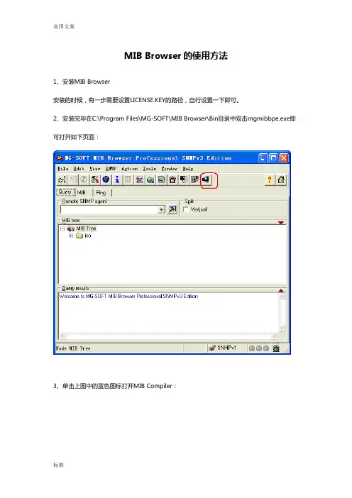
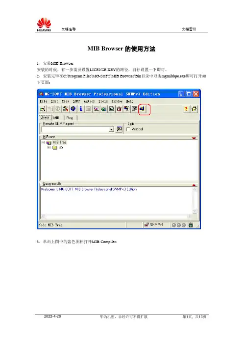
MIB Browser的使用方法1、安装MIB Browser安装的时候,有一步需要设置LICENSE.KEY的路径,自行设置一下即可。
2、安装完毕在C:\Program Files\MG-SOFT\MIB Browser\Bin目录中双击mgmibbpe.exe即可打开如下页面:3、单击上图中的蓝色图标打开MIB Compiler:4、File>>Compile,找到CMCC-MAS.MIB,编译CMCC-MAS.MIB:5、保存编译结果:6、保存完毕,关闭MIB Compiler,回到MIB Browser:选择MIB选项>>单击蓝色的箭头>>Unload all MIB Modules>>然后在MIB Modules中选择“CMCC-MAS”(双击即可load)7、切换到“Query”选项,即可看到CMCC-MAS中定义的节点:8、在Remote SNMP Agent中填入MAS服务器的IP地址:比如我在本机测试,就填入本机的IP地址10.72.85.126。
现场使用时,填入MAS服务器的IP 即可。
9、比如我们想采集MAS服务器的CPULoad信息:选择cpuLoad>>点右键>>ContactContact之后,MASAgent回返回一个sysUpTime。
下图注意两个地方,其一:协议类型是SNMPv1(后面会把它替换为SNMPv2);其二:MAS服务器的MASAgent返回了一个sysUpTime。
如果MAS服务器无法Contact,那么一定时间后MIB Browser会返回TimeOut。
此时需要检查MAS服务器的161端口是否开放,确认MASAgent的“网管平台IP鉴权功能”是否关闭,并检查网络情况。
也可以跟踪MASAgent的日志确认MASAgent是否接收到MIB Browser的GET请求。
10、Contact成功后,就可以发送GET请求了:cpuLoad上点右键>>选择Get采集到的信息如下:CPULoad的信息为7% 其他的信息采集操作类似。
![V2020PCM复用设备使用说明书V2[1][1].20](https://uimg.taocdn.com/84f5c58f51e79b896802269c.webp)
Vango系列V2020 PCM复用设备使用说明书广州市高科通信技术股份有限公司Guangzhou Gaoke Communications Technology Co.,LTD.Vango系列V2020型PCM复用设备使用说明书版本:V2020-06-05-220广州市高科通信技术股份有限公司热情为客户提供全方位的技术支持,用户可与就近的高科办事处联系,也可直接与公司客服部联系。
版权声明广州市高科通信技术股份有限公司版权所有,保留一切权利。
非经本公司书面许可,任何单位和个人不得擅自摘抄、复制本书内容的部分或全部,并不得以任何形式传播。
®为广州市高科通信技术股份有限公司的商标,不得仿冒。
Copyright by Guangzhou Gaoke Communications Technology Company Limited.All rights are reserved.No Part of this document may be reproduced or transmitted in any form or by any means without prior written consent of Guangzhou Gaoke Communications Technology Company Limited.®is the trademarks of Guangzhou Gaoke Communications Technology Company Limited. No the trademarks may be counterfeited.免责声明广州市高科通信技术股份有限公司保留修订本出版物和随时修改本文档内容而不预先通知任何人的权利。
Guangzhou Gaoke Communications Technology Company Limited reserves the right to change the document from time to time at its sole discretion, and not to make the notice to anyone in advance.前言内容简介本使用说明书主要描述V2020 PCM复用设备的功能及使用说明。
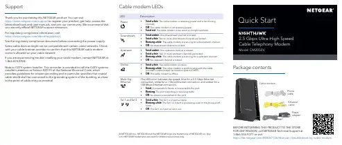
Package contentsPower adapterFOR ANY REASON, call NETGEAR Technical Support at 1-866-534-9377 or visithttps:///000061156/How-can-I-troubleshoot-my-cable-modem .Cable modem LEDsLEDDescriptionPower• Solid white . The cable modem is receiving power and is functioning normally.• Off . The cable modem is not receiving power.•Solid red . The cable modem is too warm and might overheat.Downstream• Solid amber . One downstream channel is locked.• Solid white . Two or more downstream channels are locked.• Blinking white . The cable modem is scanning for a downstream channel.• Off . No downstream channel is locked.Upstream• Solid amber . One upstream channel is locked.• Solid white . Two or more upstream channels are locked.• Blinking white . The cable modem is scanning for a upstream channel.• Off . No upstream channel is locked.Online• Solid white . The cable modem is online.• Blinking white . The cable modem is synchronizing with the cable provider’s cable modem termination system (CMTS).•Off . The cable modem is offline.Multi-Gig EthernetThe LED color indicates the speed: blue for a 2.5 Gbps Ethernetconnection, white for a 1 Gbps Ethernet connection, and amber for a 100 Mbps Ethernet connection.• Solid . A powered-on device is connected to the port.• Blinking . The port is sending or receiving traffic.•Off . No device is connected to this port.Tel 1 and Tel 2• Solid white . The Tel 1 or 2 port is online.• Blinking white . The Tel 1 or 2 port is processing a call or the phone is off-hook.•Off . The Tel 1 or 2 port is not in use.© NETGEAR, Inc., NETGEAR and the NETGEAR Logo are trademarks of NETGEAR, Inc. Any non-NETGEAR trademarks are used for reference purposes only.Thank you for purchasing this NETGEAR product. You can visithttps:///support to register your product, get help, access the latest downloads and user manuals, and join our community. We recommend that you use only official NETGEAR support resources.For regulatory compliance information, visit https:///about/regulatory/.See the regulatory compliance document before connecting the power supply.Some cable devices might not be compatible with certain cable networks. Check with your cable Internet provider to confirm that this NETGEAR cable modem router is allowed on your cable network.If you are experiencing trouble installing your cable modem, contact NETGEAR at 1-866-874-8924.SupportNote to CATV system Installer- This reminder is provided to call the CATV systems installer’s attention to Section 820-93 of the National Electrical Code, whichprovides guidelines for proper grounding and in particular, specifies that coaxial cable shield shall be connected to the grounding system of the building, as close to the point of cable entry as practical.1. Turn off and disconnect existing modems and routers.If you are replacing a modem that is currently connected in your home, unplug the modem and plug the new cable modem into the same outlet.2. Use a coaxial cable to connect the cable port on the cable modem to a cablewall outlet.We recommend that you3. on the cable modem with the phone cable.If you subscribed to two phone lines, connect the other phone to the Tel 2 port.Note: The Tel 2 port only works for a two-phone line subscription.4. Connect the power adapter to the cable modem and plug the power adapterinto an electrical outlet.Coaxial cableStart hereThe cable modem might reset multiple times when it is powered on. 5. Wait for the Online LEDto light solid white.This process might take up to 10 minutes. When the cable modem comes online, the Online LED stops blinking and lights solid white.After 10 minutes, if the Online LED doesn’t light solid, make sure that thecable outlet is working or call your Internet service provider (ISP) to make sure you have service.Note: When the Online LED lights solid, your cable modem is not connected to the Internet yet. You must connect a router or computer to your cable modem and then activate your cable modem with your cable Internet provider.6. Connect a router to your cable modem.c. Connect your computer or mobile device to the router.7. Collect this information about your Internet service and the cable modem:•Your Xfinity account number and the personal information associated with your Xfinity account (you need one of the following): -Mobile phone number-Xfinity user name and password•The following information from the cable modem label:-Model number, which is CM2050V-Serial numberNETGEAR, Inc.350 East Plumeria Drive San Jose, CA 95134, USANETGEAR INTERNATIONAL LTD Floor 1, Building 3University Technology Centre Curraheen Road, Cork, T12EF21, IrelandApril 2020-MAC address-MTA MAC address8. Activate your Internet service:a. Close all web browsers.b. Launch a web browser.You are redirected to the Xfinity self-activation page. If you are not redirected to the Xfinity self-activation page, visit /activate .c. Provide your Xfinity credentials and complete the self-activation process.This process might take up to 10 minutes, during which the cable modem reboots twice.If you’re unable to activate your Xfinity Internet service using the self-activation page, call Xfinity customer service at 1-800-XFINITY (1-800-934-6489).。


无线校园网使用指南项目概况我校无线校园网于2011年8月开始规划实施,按照以下总体要求进行建设:1、采用802.11n标准,达300Mbps,是目前无线校园网中最先进的标准。
2、面向智能终端。
无线校园网可以满足笔记本、平板电脑、智能手机等终端设备上网;上网设备使用的操作系统主要有Windows、Ios、Android等。
目前使用802.1x接入认证,上网设备必须支持这种认证方式。
3、采取密布形式。
在大教室、大会议室等场所,采取无线接入点(AP)密布的形式建设,以满足多用户的接入需求。
4、无线校园网采取校企合作共建的模式,一套硬件设施,支持多个无线网运行。
用户终端将出现教师SSID(ZstuTeacher)、学生SSID(ZstuStudent)、访客SSID(ZstuGuest)、中国移动SSID(C MCC、CMCC-EDU)、中国联通SSID(ChinaUnicom)。
其中ZstuTeacher、ZstuStudent和ZstuGu est为学校管理的无线网。
教师用户免费上内外网。
学生用户免费上校内网,使用学生宿舍帐户上校外网。
访客用户主要是外单位来学校的人员,未通过认证前没有任何访问内外网的权限,但是可以在访客之间交换和共享数据;如需访问校园内网,必须通过VPN帐号认证。
用于访客的VPN帐号由学校网络信息中心统一分发各部门,各部门负责所分配VPN帐号的管理。
中国移动和中国联通等通讯运营商的SSID需要用户个人交纳通讯套餐费用才能获得帐号使用,帐号由通讯运营商分发和管理。
今后若有其他通讯运营商参与我校信息化合作共建项目,无线校园网中也将增加其他通讯运营商的SSID,以供用户使用。
5、统一认证,方便使用。
教师和学生用户使用数字化校园的帐户和密码上无线校园网,第一次使用需要激活一下帐号。
6、统一规划,分步实施。
无线校园网一期工程建设下沙和西城两个校区教学区的无线校园网,后续将建设学生宿舍区的无线校园网。
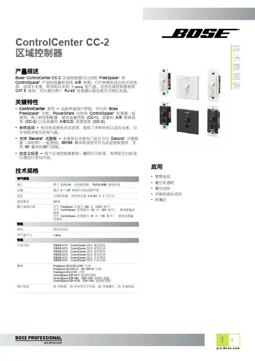
技术数据表ControlCenter CC-2区域控制器产品描述Bose ® ControlCenter CC-2 区域控制器可以控制 FreeSpace ® 和ControlSpace ® 产品的音量和选择 A/B 音源。
它们有黑色或白色可供选择,适用于北美、欧洲和日本的 1-gang 电气盒。
这些区域控制器使用 CAT 5 接线,可以通过两个 RJ-45 连接器以菊花链方式简化连接。
关键特性• ControlCenter 系列 – 远程终端用户界面,可以和 BoseFreeSpace ® 功放、PowerShare 功放和 ControlSpace ® 处理器一起使用。
有三种控制配置,提供音量控制 (CC-1)、音量和 A/B 音源选择 (CC-2) 以及音量和 A/B/C/D 音源选择 (CC-3)。
• 多样选项 – 有白色或黑色可供选择,提供了多种外形以适应北美、日本和欧洲常见的电气盒。
• 支持 Decora ® 式壁板 – 北美和日本版专门设计为与 Decora ® 式壁板盖(未附带)一起使用。
86×86 毫米欧洲型号作为成品壁板提供,支持 60 毫米的螺钉间隔。
• 自定义标签 – 每个区域控制器都有一叠预打印标签,有两张空白标签以便自行添加内容。
技术规格产品代码768938-0110 ControlCenter CC-2 美国黑色768938-0210 ControlCenter CC-2 美国白色768938-2110 ControlCenter CC-2 欧洲黑色768938-2210 ControlCenter CC-2 欧洲白色768938-3110 ControlCenter CC-2 日本黑色768938-3210ControlCenter CC-2 日本白色兼容FreeSpace IZA 2120-LZ/HZ 功放FreeSpace IZA 250-LZ 、IZA-190-HZ 功放FreeSpace DXA 2120 功放ControlSpace ESP-00 II 音频处理器ControlSpace ESP-880、ESP-1240 音频处理器ControlSpace ESP-4120、ESP-1600 音频处理器箱内物品(1) 控制器,(1) 彩色预打印标签,(2) 安装螺钉,(1) 安装指南应用• 零售商店• 餐厅和酒吧• 餐饮场所• 宗教和祷告场所•附属区技术数据表连接面板ControlCenter CC-2区域控制器音量旋钮:线性锥形 10 kΩ 电位器。

© 2020 CommScope, Inc. All rights reserved. | IG-114469-EN (04/20) © 2021 CommScope, Inc. All rights reserved. | IG-114492.1-EN (04/21) To learn more, contact your RUCKUS networking solution provider or visit /analytics.Automates manual tasks. 1.IT can spend a lot of time manually reviewing log files and reports trying to troubleshoot and to glean insight into network operations. But this approach falls apart if the network is generating too much data. Advanced analytics tools automatically process this raw data and deliver it as actionable insight.Mean time to resolution (MTTR) is a key performance metric in many organizations. Network analytics tools can enable faster troubleshooting by providing remediation recommendations based on root cause analysis or by providing granular, client-level detail. Both allow helpdesk tickets to be closed more quickly—keeping them from piling up. 2.Accelerates network and client troubleshooting. IT often finds itself in reactive mode, responding to issues only once they’re affecting a large number of users. Advanced tools can identify network anomalies before they become service-affecting, enabling IT to take action to stop incidents before they happen. Reduces the number of service-affecting incidents. 3.4.Helps IT teams to prioritize. It’s frequently hard to tell which service issues to address first, especially if those service issues are user-reported. Some analytics software can automatically classify service incidents by severity, allowing IT to tackle the most critical issues first, thereby minimizing user-experienced downtime .Monitors network health.5.Without the right tools in place, measuring network performance to SLAs can be a chore, if it can even be done at all. With the right tool in place, IT can define SLA thresholds—and automatically monitor them—so IT knows exactly how users are experiencing the network and whether new changes are having the desired effect.FIVE WAYS advanced network analytics makes life easier for IT teams。
MIB Browser的使用方法1、安装MIB Browser安装的时候,有一步需要设置LICENSE.KEY的路径,自行设置一下即可。
2、安装完毕在C:\Program Files\MG-SOFT\MIB Browser\Bin目录中双击mgmibbpe.exe即可打开如下页面:3、单击上图中的蓝色图标打开MIB Compiler:4、File>>Compile,找到CMCC-MAS.MIB,编译CMCC-MAS.MIB:5、保存编译结果:6、保存完毕,关闭MIB Compiler,回到MIB Browser:选择MIB选项>>单击蓝色的箭头>>Unload all MIB Modules>>然后在MIB Modules中选择“CMCC-MAS”(双击即可load)7、切换到“Query”选项,即可看到CMCC-MAS中定义的节点:8、在Remote SNMP Agent中填入MAS服务器的IP地址:比如我在本机测试,就填入本机的IP地址10.72.85.126。
现场使用时,填入MAS服务器的IP 即可。
9、比如我们想采集MAS服务器的CPULoad信息:选择cpuLoad>>点右键>>ContactContact之后,MASAgent回返回一个sysUpTime。
下图注意两个地方,其一:协议类型是SNMPv1(后面会把它替换为SNMPv2);其二:MAS服务器的MASAgent返回了一个sysUpTime。
如果MAS服务器无法Contact,那么一定时间后MIB Browser会返回TimeOut。
此时需要检查MAS服务器的161端口是否开放,确认MASAgent的“网管平台IP鉴权功能”是否关闭,并检查网络情况。
也可以跟踪MASAgent的日志确认MASAgent是否接收到MIB Browser的GET请求。
10、Contact成功后,就可以发送GET请求了:cpuLoad上点右键>>选择Get采集到的信息如下:CPULoad的信息为7% 其他的信息采集操作类似。
ORDERING DATA: SERIES 5360 PROXIMITY SWITCHESTO ORDER SPECIFY:NOTES:1)2)CORDSETS8-68-7BENEFITS: SERIES 5360 HALL EFFECT SWITCHESBENEFITS■ Series 5360 Hall Effect Switches are available for use on selectedPHD products, making it easy to interface these actuators with various electronic controls.■ Switches have no moving parts or mechanical contacts,providing long switch life and elimination of contact bounce.■ Constant amplitude output is provided for use with most digitallogic systems.■ Low profile integral clamp mounting is easy to adjust over theentire piston travel of the cylinder or actuator.■ Several switches may be mounted to control or initiate anysequence or function.■ Dual LED indicators provide convenient means for positioningand troubleshooting circuits. Green LED shows that power is being received at the switch and amber shows when the switch output is on.■ Available in a Quick Connect model for easy installationand maintenance.Series 5360 Hall Effect Switches are designed specifically to provide an input signal to various types of programmable controllers or logic systems. Since Hall Effect Switches are solid-state, there are no moving parts to wear out. They offer an infinite number of trouble-free operations. Hall Effect Switches operate on DC current only.MODEL NO. 53604 & 53624 - PNP (SOURCE)INPUT - 4.5-24 VDCLOAD CURRENT - 100 mA. MAX.SWITCH HOUSING COLOR - RED(LED’s have been omitted from the schematic for clarity.)MODEL NO. 53603 & 53623 - NPN (SINK)INPUT - 4.5-24 VDCLOAD CURRENT - 20 mA. MAX.SWITCH HOUSING COLOR - YELLOW(LED’s have been omitted from the schematic for clarity.)CABLED MODEL 53603QUICK CONNECT MODEL 53623QUICK CONNECT MODEL 53624CABLED MODEL 53604HALL EFFECT WIRING SCHEMATICSBROWNBLUE BLACKBROWN BLUEBLACKBENEFITS: SERIES 5360 SOLID STATE SWITCHESBENEFITS■Series 5360 Solid State Switches are available for use onselected PHD products, making it easy to interface theseactuators with various electronic controls.■Switches are solid state, having no moving parts or mechanicalcontacts, providing long switch life and elimination ofcontact bounce.■Transient voltage protection.■Constant amplitude output is provided for use with most digitallogic systems.■Reverse polarity protection.■Low profile integral clamp mounting is easy to adjust over theentire piston travel of the cylinder or actuator.■Several switches may be mounted to control or initiate anysequence or function.■Dual LED indicators provide convenient means for positioningand troubleshooting circuits. Green LED shows that power isbeing received at the switch and amber shows when the switchoutput is on.■Available in a Quick Connect model for easy installationand maintenance.Series 5360 Solid State Switches are designed specificallyto provide an input signal to various types of programmablecontrollers or logic systems. Since Solid State Switches have nomoving parts to wear out, they offer an infinite number of trouble-free operations. Solid State Switches operate on DC current only.MODEL NO. 53606 & 53626 - PNP (SOURCE)INPUT - 6-24 VDCLOAD CURRENT - 100 mA. MAX.SWITCH HOUSING COLOR - ORANGE(LED’s have been omitted from the schematic for clarity.) MODEL NO. 53605 & 53625 - NPN (SINK)INPUT - 6-24 VDCLOAD CURRENT - 20 mA. MAX.SWITCH HOUSING COLOR - BLACK(LED’s have been omitted from the schematic for clarity.)CABLED MODEL 53605QUICK CONNECT MODEL 53625QUICK CONNECT MODEL 53626CABLED MODEL 53606SOLID STATE WIRING SCHEMATICSBROWNBLUEBLACKBROWNBLUEBLACK8-88-9DIMENSIONS: SERIES 5360 HALL/SOLID STATE SWITCHESHALL EFFECT AND SOLID STATE SWITCHHALL EFFECT AND SOLID STATE SWITCH WITH MALE QUICK CONNECT7.4][10.2]63549-xx CORDSET WITH FEMALE QUICK CONNECTNUMBERS IN [ ] ARE IN mm–IMPERIAL EQUIVALENTS ARE PROVIDED FOR CONVENIENCEAll dimensions are reference only unless specifically toleranced.8-10[10.2]63549-xx CORDSET WITH FEMALE QUICK CONNECTNUMBERS IN [ ] ARE IN mm – IMPERIAL EQUIVALENTS ARE PROVIDED FOR CONVENIENCEDIMENSIONS: SERIES 5360 REED SWITCHESREED SWITCHREED SWITCH WITH MALE QUICK CONNECTBENEFITS: SERIES 5360 REED SWITCHESBENEFITS■ Series 5360 Reed Switches are available for use on selectedPHD products, making it easy to interface these actuators with various electronic controls.■Low profile integral clamp mounting is easy to adjust over theentire piston travel of the cylinder or actuator.■ Several switches may be mounted to control or initiate anysequence or function.■ An LED indicator provides convenient means for positioningand troubleshooting circuits.■ Available in a Quick Connect model for easy installationand maintenance.■ Special current limit model available for AC applications whereinrush might otherwise damage the switch.Series 5360 Reed Switches are available in either AC or DC models. They are ideal for use as inputs for many types ofsequencers and programmable controllers. In some cases, they can be used to drive some relays or valve solenoids. However, electrical transients (inrush currents or line spikes) associated with inductive or capacitive loads can damage and shorten the life of the switch.NUMBERS IN [ ] ARE IN mm – IMPERIAL EQUIVALENTS ARE PROVIDED FOR CONVENIENCE7.4]* CE certification not applicable to these switch models.All dimensions are reference only unless specifically toleranced.8-11MODEL NO. 53602-2 & 53622-2 - NPN (SINK) OR PNP (SOURCE)INPUT - 4.5-24 VDCPOWER CAPACITY - 4 WATT MAX.LOAD CURRENT - 200 mA. MAX.MODEL NO. 53609-2 & 53629-2INPUT - 110-120 VACSWITCHED POWER - 2.5 WATT MAX.INTERNAL RESISTANCE - 1.5 kOhm SWITCH HOUSING COLOR - GREENCABLED MODEL 53609-2QUICK CONNECT MODEL 53629-2REED WIRING SCHEMATICSCABLED MODEL 53602-2 - NPN (SINK)CABLED MODEL 53602-2 - PNP (SOURCE)QUICK CONNECT MODEL 53622-2 - NPN (SINK)QUICK CONNECT MODEL 53622-2 - PNP (SOURCE)SWITCH HOUSING COLOR - WHITE(Bi-polar LED emits a green light in the Sinking circuit and a red light in the Sourcing circuit.)BROWNBLUEBLACK BROWNBLUEBLACKBROWNBLUEBLACKENGINEERING DATA: SERIES 5360 REED SWITCHESAll dimensions are reference only unless specifically toleranced.。
Package contentsEthernet cablePower adapterBEFORE RETURNING THIS PRODUCT TO THE STORE FOR ANY REASON, call NETGEAR Technical Support at 1-866-534-9377 or visithttps:///000061156/How-can-I-troubleshoot-my-cable-modem.Cable modem LEDsLEDDescriptionPower• Solid green . The cable modem is receiving power and is functioning normally.• Off . The cable modem is not receiving power.•Solid red . The cable modem is too warm and might overheat.Downstream• Solid amber . One downstream channel is locked.• Solid green . Two or more downstream channels are locked.• Blinking green . The cable modem is scanning for a downstream channel.• Off . No downstream channel is locked.Upstream• Solid amber . One upstream channel is locked.• Solid green . Two or more upstream channels are locked.• Blinking green . The cable modem is scanning for a upstream channel.• Off . No upstream channel is locked.Online• Solid green . The cable modem is online.• Blinking green . The cable modem is synchronizing with the cable provider’s cable modem termination system (CMTS).•Off . The cable modem is offline.Ethernet• Solid . A powered-on device is connected to this port.• Blinking . The port is sending or receiving traffic.•Off . No device is connected to this port.© NETGEAR, Inc., NETGEAR and the NETGEAR Logo are trademarks of NETGEAR, Inc. Any non-NETGEAR trademarks are used for reference purposes only.Visit /support to get your questions answered and access the latest downloads.You can also check out our NETGEAR Community for helpful advice at .Customer-owned cable devices might not be compatible with certain cable networks. Check with your cable Internet provider to confirm that this NETGEAR cable device is allowed on your cable network.If you are experiencing trouble installing your cable modem, contact NETGEAR at 1-866-874-8924.Support and CommunityThe following table lists support contact information for cable Internet providers that support your cable modem.Cable Internet ProviderSupport Contact Information Coxhttps:///residential/support/home.html https:///activate 1-888-556-1193Mediacom https:// 1-855-Mediacom (1-855-633-4226)Optimumhttps:///support/contact-us https:///JointInstall 1-877-810-6750Sparklight https:// 1-877-692-2253Spectrumhttps:///contact-us https:// 1-833-267-6094Xfinityhttps:///support/articles/activate-purchased-modem /activate1-800-XFINITY (1-800-934-6489)1. Turn off and disconnect existing modems and routers.If you are replacing a modem that is currently connected in your home, unplug the modem and plug the new cable modem into the same outlet.2. Connect a coaxial cable.Use a coaxial cable to connect the cable port on the cable modem to a cable wall outlet. Make sure that the cable is tightly connected. We recommend that you connect your cable modem directly to a cable wall outlet.Connect the power adapter to the cable modem and plug the power adapter into an electrical outlet.The cable modem might reset multiple times when it is powered on. 4. Wait for the Online LEDto light solid green.This process might take up to 10 minutes. When the cable modem comes online, the Online LED stops blinking and lights solid green for at least a minute.Power adapterCoaxial cableStart hereAfter 10 minutes, if the Online LED doesn’t light solid, make sure that the cable outlet is working, or call your Internet service provider (ISP) to make sure you have service.Note: When the Online LED lights solid, your cable modem is not connected to the Internet yet. You must connect a router or computer to your cable modem, and then activate your cable modem with your cable Internet provider.5. Use an Ethernet cable to connect the LAN port on your cable modem toeither a router or a computer. (The computer must have an Ethernet port.)• Router . Connect the Ethernet cable to the WAN or Internet port on therouter, power on the router, and then connect your computer to the router using WiFi or Ethernet.• 6. • Your cable Internet provider (ISP) account information• Cable modem model number, which is CM500• Cable modem serial number •Cable modem MAC addressNETGEAR, Inc.350 East Plumeria Drive San Jose, CA 95134, USANETGEAR INTERNATIONAL LTD Floor 1, Building 3University Technology Centre Curraheen Road, Cork, T12EF21, IrelandJune 20207. Activate your Internet service:The following table lists the activation contact information for cable Internet providers that support your cable modem. Cable Internet ProviderActivation Contact Cox 1-888-556-1193Mediacom 1-855-Mediacom (1-855-633-4226)Optimum 1-877-810-6750Sparklight 1-877-692-2253Spectrum 1-833-267-6094XfinityVisit /activate and follow the prompts to activateYour ISP’s contact information might change. You can also find the contact information in your monthly Internet service billing statement.Regulatory and LegalFor regulatory compliance information including the EU Declaration of Conformity, visit https:///about/regulatory/.See the regulatory compliance document before connecting the power supply.For NETGEAR’s Privacy Policy, visit https:///about/privacy-policy.By using this device, you are agreeing to NETGEAR’s Terms and Conditions athttps:///about/terms-and-conditions. If you do not agree, return the device to your place of purchase within your return period.Note to CATV system Installer- This reminder is provided to call the CATV systems installer’s attention to Section 820-93 of the National Electrical Code, which provides guidelines for proper grounding and, in particular, specifies that coaxial cable shield shall be connected to the grounding system of the building as close to the point of cable entry as practical.。
Key FeaturesThe SD9366-EH-v2 is the latest professional IR speed dome camera with wiper from VIVOTEK, specifically designed to enhance low light surveillance in large coverage areas. Equipped with 250M IR illuminators and a 30x optical zoom lens, the SD9366-EH-v2 provides a superb low light image in the most challenging situations. The camera also adopts VIVOTEK's Smart IR II technology, Vari-Angle IR. VIVOTEK's Vari-Angle IR provides smooth vari-angle adjustment of the IR illuminators, allowing broad coverage FOV and highly uniform IR intensity while avoiding hot-spots traditionally associated with IR illumination.The SD9366-EH-v2 is the PTZ surveillance camera with IR Illumination to utilize H.265 compression technology. When combined with VIVOTEK's Smart Stream II technology users can obtain bandwidth savings of up to 80%* compared to traditional• H .265 Compression technology • 1080P Full HD CMOS Sensor • 60 fps @ 1080p Full HD • 30x Zoom Lens• 250M IR with Smart IR II (Vari-Angle IR)• 360° Continuous Pan and 220° Tilt• R emovable IR-cut Filter for Day & Night Function • W DR Pro for Unparalleled Visibility in High Contrast Environments • W eather-proof IP66-rated, Vandal-proof IK10 and NEMA 4X-rated Housing • -50°C ~ 55°C Wide Temperature Range for Extreme Weather Conditions • E IS (Electronic Image Stabilization) to Control Image Stability • E asy Cleaning with Built-in WiperH.264. By combining 1080p full HD resolution with H.265, IR illuminators, Vari-Angle IR, WDR, and 30x optical zoom, the SD9366-EH-v2 is able to capture fine details at top-notch quality, 24 hours a day, 7 days a week.VIVOTEK further strengthened the camera performance with an IP66- and NEMA 4X-rated housing to protect the camera against rain, dust, and corrosion. The SD9366-EH-v2 has a wide operating temperature range from -50°C to 55°C, ensuring continuous operation under the most extreme weather conditions and hazardous environments. This makes the SD9366-EH-v2 ideally suited to monitor wide open spaces such as ports, highways, cities, and parking lots where high-level precision is required.* Depending on scene.Without Smart IR IIWith Smart IR IISD9366-EH-v2Speed Dome Network CameraModel SD9366-EH-v2System InformationCPU Multimedia SoC (System-on-Chip) Flash128 MBRAM512 MBCamera FeaturesImage Sensor1/2.8" Progressive CMOSMax. Resolution1920x1080 (2MP)Lens Type30x Optical Zoom, Auto Focus Focal Length f = 4.3 ~ 129 mm (30x zoom) Aperture F1.6 ~ F4.7Iris Type DC-irisField of View 64° ~ 2.3° (Horizontal) 36° ~ 1.3° (Vertical) 73° ~ 2.6° (Diagonal)Shutter Time 1 sec. to 10,000 sec. WDR Technology WDR ProDay/Night YesRemovable IR-cut Filter YesMinimum Illumination *************(Color)************(B/W)0 Lux with IR illumination onPan Speed0.1° ~ 300° / sec. Pan Range360° endlessTilt Speed0.1° ~ 300° / sec. Tilt Range220° (-110° ~ +110°)Preset Locations256 preset locations128 presets per tourPan/Tilt/Zoom Functionalities 48x digital zoom (4x on IE plug-in, 12x built-in), Auto pan mode, Auto patrol modeIlluminators Built-in 850nm IR Illuminators up to 250meters with Smart IR II, IR LED*2Storage Seamless Recording to MicroSD/SDHC/ SDXC card and recording to network-attached storage (NAS)VideoCompression H265, H264, MJPEGMaximum Frame Rate H.265 & H.264: 60 fps @ 1920x1080MJPEG: 30 fps @ 1920x1080Maximum Streams 4 video streams(Up to 9 configurable profiiles)S/N Ratio66 dBDynamic Range130 dBVideo Streaming Adjustable resolution, quality and constantbit rate control, Smart Stream II Image SettingsTime stamp, text overlay, flip and mirror,configurable brightness/contrast/saturation/sharpness, white balance,exposure control, gain, backlightcompensation, privacy masks (Up to 24),scheduled profile settings, defog, 3DNR, EIS,HLCAudioAudio Capability Two-way Audio (full deuplex) Compression G.711, G.726Interface External microphone inputExternal line outputNetworkUsers Live viewing for up to 10 clientsSecurityAccess list, digest authentication, HTTPS ,IEEE 802.1x, Password protection, signedfirmware, Trend Micro IoT Security (bruteforce attack event, cyberattack event,quarantine event), user access log, useraccount managementProtocols802.1X, ARP, Bonjour, CIFS/SMB, DDNS,DHCP, DNS, FTP, HTTP, HTTPS, ICMP, IGMPv3,IPv4, IPv6, NTCIP, NTP, PPPoE, QoS (CoS/DSCP), RTSP/RTP/RTCP, SMTP, SNMP, SSL, TCP/IP, TLS 1.2, UDP, UPnPInterface10 Base-T/100 Base-TX Ethernet (RJ-45)*It is highly recommended to use standardCAT5e & CAT6 cables which are compliantwith the 3P/ETL standard.ONVIF Profile G, S, T supported, specificationavailable at Solution IntegrationVideo Motion Detection Five-window video motion detectionAuto-Tracking Auto-tracking on moving objectVADP Package Trend Micro (3-year free trial), Stratocast Alarm and EventEvent TriggerAudio detection, camera tamperingdetection, cybersecurity events (bruteforce attack event, cyberattack event,quarantine event), digital input, manualtrigger, motion detection, periodicaltrigger, recording notification, SD card lifeexpectancy, system bootEvent ActionEvent notification via audio clip, digitaloutput, email, HTTP, FTP, NAS server, SD card,push notificationFile upload via email, HTTP, FTP, NAS server,SD cardGeneralConnectorsRJ-45 cable connector for 10/100MbpsNetwork/PoE connectionAudio line inputAudio line outputAC/DC 24V power inputDigital input *4Digital output *2RS-485 (Pelco D, Baud rate 2400)* 1LED Indicator System power and status indicatorPower InputAC 24V, DC 24V, PoH/PoE (95W)(Simultaneous Power RedundancySupported)Power ConsumptionAC/DC 24V:Max. 63 W (Heater on) Max. 45 W (Heater off) PoH/PoE (95W):Max. 70 W (Heater on) Max. 51 W (Heater off)Dimensions 237 x 364 mmWeight 7.1 kg (with bracket) 5.7 kg (without bracket)CertificationsEMC: CE, LVD, FCC Class A, VCCI; Safety: UL; Environment: IK10, IP66, NEMA 4X Operating TemperatureStarting Temperature:-40°C ~ 55°C (-40°F ~ 131°F) Working Temperature:-40°C ~ 55°C (-40°F ~ 131°F) (DC 24V) -50°C ~ 55°C (-58°F ~ 131°F) (AC 24V/PoH (95W))*Wiper is functional at 10°C to 55°C (50°F to 131°F)Humidity 98% RH (non-condensing)Warranty36 monthsSystem RequirementsOperating SystemMicrosoft Windows 10/8/7 Mac 10.12 (Chrome only)Web Browser Chrome 58.0 or above Internet Explorer 10/11Other PlayersVLC: 1.1.11 or aboveIncluded AccessoriesPacking ContentsWall mount bracket, I/O cable, screws, waterproof connectors, terminal blocks, quick installation guide, alignment sticker, ground wire, T25 star driver, desiccant bagsDimensionsCompatible AccessoriesCabinetAT-CAS-001AT-CAB-002AT-SUN-002AT-SWH-000Cabinet for SpeedDome Cabinet for HLG PowerSupplySunshield Power Safety KitMounting KitsOthersAM-220AM-529AE-301AJ-001AJ-002AO-007Wall Mount Bracket (standard package)Mounting AdapterWater Tank,24VAC/DC, 0˚C ~ 60˚CUSB Joystick USB Joystick I/O Combo CablePower Adapter24VAC24VDCAA-352HLG-120H-24Outdoor Power Box, 24VAC/144W, IP67, IK10Industrial 24VDC/120W Power Supply, IP67All specifications are subject to change without notice. Copyright © VIVOTEK INC. All rights reserved. Ver. 46F,No.192,Lien-ChengRd.,Chung-Ho,NewTaipeiCity,235,Taiwan,R.O.C.|T:+886-2-82455282|F:+886-2-82455532|E:*****************|W:Compatible Accessories95W PoH/PoEAP-GIC-011A-095AP-GIC-015B-0951xGE 95W PoH/PoE Injector with Surge Protection 12KVOutdoor 1xGE 95W PoH/PoE Injector with Surge Protection 12KV, IP67,IK10。