德菲尔曼操作手册
- 格式:doc
- 大小:6.42 MB
- 文档页数:22
OPERATOR'S MANUALINTERFACE UNITIF-NMEASC MODELwww.furuno.co.jpIMPORTANT NOTICES• This manual is intended for use by readers with a solid knowledge of English.• No part of this manual may be copied or reproduced without written permission.• If this manual is lost or worn, contact your dealer about replacement.• The contents of this manual and equipment specifications are subject to change without notice.• Store this manual in a convenient place for future reference.• FURUNO will assume no responsibility for the damage caused by improper use or modification of the equipment (including software) by an unauthorized agent or a third party.• When it is time to discard this product it must be done according to local regulations for disposal of industrial waste. For disposal in the USA, refer to the Electronics Industries Alliance (http:// /).SAFETY INSTRUCTIONSSAFETY INSTRUCTIONSTABLE OF CONTENTS FOREWORD (v)SYSTEM CONFIGURATION (vi)1.MOUNTING (1)1.1Equipment List (1)1.2Mounting Procedure (1)2.WIRING (2)3.ADJUSTMENTS (4)3.1LEDs and Equipment Status (4)3.2Setting Up NMEA Ports (5)3.3Heading, Pitch and Roll Offsets (8)4.OPERATION (9)5.MAINTENANCE, TROUBLESHOOTING (10)5.1Preventive Maintenance (10)5.2Replacing the Fuse (11)5.3Troubleshooting (11)5.4Self Test (12)5.5Memory Clear (13)SPECIFICATIONS.....................................................................................................SP-1 OUTLINE DRAWING...................................................................................................D-1 INTERCONNECTION DIAGRAM................................................................................S-1FOREWORDA Word to the Owner of the IF-NMEASCCongratulations on your choice of the FURUNO IF-NMEASC Interface Unit. We are confident you will see why the FURUNO name has become synonymous with quality and reliability.For 60 years FURUNO Electric Company has enjoyed an enviable reputation for quality marine electronics equipment. This dedication to excellence is furthered by our extensive global network of agents and dealers.This equipment is designed and constructed to meet the rigorous demands of the marine environ-ment. However, no machine can perform its intended function unless installed, operated and maintained properly. Please carefully read and follow the recommended procedures for installa-tion, operation and maintenance.Thank you for considering and purchasing FURUNO equipment.FeaturesThe IF-NMEASC is a dedicated interface unit for the SC-30 Satellite Compass. It receives NMEA 2000®* format heading, pitch, roll and GPS position data from the SC-30, converts them to NMEA 0183 format data and outputs the converted data to external equipment.• Input port: One NMEA 2000 format port• Four output ports: NMEA 0183x2, AD-10x1, Analog (pitch and roll)x1• Offsets for heading, pitch and roll*: NMEA 2000 is a registered trademark of the National Marine Electronics Association USA.SYSTEM CONFIGURATION1.MOUNTING1.1Equipment List1.2Mounting ProcedureWhen choosing a mounting location for the unit, keep the following points in mind:• Select a location where shock and vibration are minimal.• Locate the unit away from places subject to rain or water splash.• Keep the unit away from exhaust pipes and vents.• Locate the unit out of direct sunlight because of heat that can build up inside its cabinet.• The location should be well ventilated.• Observe the maintenance space mentioned in the outline drawing at the back of this manual and the compass safe distances in the safety instructions.• Fix the unit with four φ3x10 self-tapping screws (supplied).NameType Code No.Qty RemarksInterface Unit IF-NMEASC -1InstallationMaterials CP20-03001001-023-400 1 set • Cable ties (CN-150N, 12 pcs.)• Self-tapping screws (φ3x10, 4 pcs.)Spare PartsSP20-01301001-019-8001 setFuse FGMB 125V 2A (3 pcs.)2.WIRINGOpen the IF unit with your hands, detach the shield cover and connect external equipment, refer-ring to the illustration below and the interconnection diagram. Cables are mainly connected to the unit with WAGO connectors. See the instructions below for how to attach wiring to the connectors. The opener for the WAGO connectors is attached to the inside of the inner cover. Fix cables to their respective cable posts with cable ties (supplied). Run a ground wire (IV-2.0sq., local supply) between the ground terminal and ship's grounding bus. Supply power from breaker on mains switchboard.P o w e r c a b l eJ 8 (A n a l o g )J 7 (S C -30 S e n s o r )J 5 (N M E A 0183)J 4 (N M E A 0183)J 3 (A D -10)G r o u n d t e r m i n a lPower cable: AWG 16-20, and diameter less than 10 mm (JIS* cable DPYC-1.5 or equivalent)Cable postRecommended Cables2. WIRING Cable construction3.ADJUSTMENTS3.1LEDs and Equipment StatusThe six LEDs above the heading indication light, flash or go off according to equipment status.LED state and equipment statusLED LED state and equipment statusGPS ON: Both GPS antennas in the SC-30 are receiving from five or more satel-lites.OFF: One of the GPS antennas is receiving from 3 or fewer satellites. OUTPUT ON: All data is output from the SC-30 normally.Flashing: Motion (heading, roll, pitch) is output (heave is fixed at 0, positionand speed are normal) by dead reckoning.OFF: Heading output is stopped.PROCESSING ON: GPS processor is functioning properly.Flashing: Initializing for GPS.OFF: Not enough satellites received.SENSOR1ON: Rate gyro normal on all three axes.OFF: Rate gyro error.SENSOR2ON: Acceleration sensor normal on all three axes.OFF: Acceleration sensor error.CR33Flashing: Valid NMEA 2000 data is input.ON: No valid NMEA 2000 data is input.OFF: CPU error, or no power.3. ADJUSTMENTS3.2Setting Up NMEA PortsPorts J4 and J5 output data in NMEA 0183 format. Select the data to output from those ports, along with baud rate and output interval. The default settings are as shown in the table below.Default settings for ports 2 and 31.Grasp the cover at its right and left sides, pull the cover outward slightly and then lift the coverto remove it.2.Open the inner cover and turn on the power.On the circuit board, find the heading indication, several LEDs, and four operating buttons. The Heading LED is lit.3.Push the [Menu/Cancel] button several times to light the Sentence LED on the Port 2 line.4.Push the [Enter] button. The Sentence LED starts flashing and the sentence currently select-ed to output from port 2 is shown with a numeric. See the illustration below for numeric and data sentence.5.Push the [+] or [-] button to display the numeric corresponding to the data sentence you wishto output.6.Push the [Enter] button. The sentence LED stops flashing.Port no.SentenceBaud rate (bps)Tx interval (ms)J4 (Port 2)HDT (Heading)4800100J5 (Port 3)ATT (Heading, pitch, roll)HVE (Heave)3840025OUTPUT PROCESSING03OUTPUT PROCESSING0033. ADJUSTMENTS7.Push the [Menu/Cancel] button to light the Bps LED on the Port 2 line.8.Push the [Enter] button. The Bps LED starts flashing and the current bps setting appears.9.Push the [+] or [-] button to select desired baud rate. The choices are 4800, 9600, 19200 and38400 (bps).10.Push the [Enter] button. The bps LED stops flashing.11.Push the [Menu/Cancel] button to light the Output interval LED on the Port 2 line.12.Push the [Enter] button. The Output Interval LED starts flashing and the current output intervalsetting appears.OUTPUT PROCESSING003OUTPUT PROCESSING003OUTPUT PROCESSING003. ADJUSTMENTS13.Push the [+] or [-] button to select desired output interval, referring to the table below.14.Push the [Enter] button. The output interval LED stops flashing.15.Set up Port 3 similar to how you did Port 2.16.Close the inner and outer covers.Sentence numberSentenceOutput interval (ms)4800 bps9600 bps19200 bps38400 bps1HDT 100, 200, 1000, 200025, 100, 200, 1000, 20002HDG 100, 200, 1000, 200025, 100, 200, 1000, 20003HDM 100, 200, 1000, 200025, 100, 200, 1000, 20004ATT, HVE 200, 1000, 2000100, 200, 1000, 200025, 100, 200, 1000, 20005VTG, GGA, ZDA 1000, 20006RMC, ZDA 1000, 20007ATT, HVE 200, 1000, 2000100, 200, 1000, 200025, 100, 200, 1000, 2000GGA, VTG, ZDA1000(<1000), 20001000(<1000), 20008HDT 100, 200, 1000, 200025, 100, 200, 1000, 2000RMC, ZDA1000(<1000), 20003. ADJUSTMENTS3.3Heading, Pitch and Roll OffsetsTurn on the IF unit and wait approx. three minutes for the satellite compass to settle. Then, check that heading, pitch and roll data are reasonable. If not, open the unit and enter appropriate off-set(s).1.Open the cover, referring to step 1 in the previous section for the procedure.2.Open the inner cover.On the circuit board, find the heading display, LED set, and operating buttons. The Heading LED is lit3.Push the [Menu/Cancel] button to light the applicable Offset LED (Heading, Pitch, or Roll) andpush the [Enter] button. The selected LED starts flashing and the display shows current offset for item e the [+] or [-] button to set offset. (You can push and hold down those buttons to speed upthe rate of incrementation.)Range of offsetHeading: ±6°Pitch, Roll: ±10°5.Push the [Enter] button to finish. The display shows current heading, pitch or roll indicationwith offset applied. The selected Offset LED stops flashing.6.Close the inner and outer covers.OUTPUT PROCESSING034.OPERATIONNormally, no operation is required except to power the unit (from the switchboard). The ST-BY LED on the cover is ON, OFF or flashing according to equipment state.Flashing: NMEA 2000 data is inputON: NMEA 2000 data is not inputOFF: Power loss, blown fuse, operation error5.MAINTENANCE, TROUBLE-SHOOTINGThis chapter provides the information for keeping your unit in good working order.5.1Preventive MaintenanceRegular maintenance is important for good performance. Following the procedures in the table be-low will help maintain performancePreventive maintenanceItem Check point RemedyReplace damaged cables.Cabling Visually check cabling forsigns of wear and damage.Ground Check ground wire.Check that ground wire is tightly fastened.Check ground point for corrosion.Cover Cleanliness of cover.Dust can be removed with a soft cloth. Do not usechemical based cleaners to clean the cover, as theycan remove paint and markings and deform the cov-er.5. MAINTENANCE, TROUBLESHOOTING5.2Replacing the FuseThe 2A fuse inside the unit protects it from overcurrent and equipment fault. If the power cannot be turned on, have a qualified technician check the fuse. If the fuse has blown, find out the cause before replacing it. If it blows again, contact your dealer for advice.5.3TroubleshootingThis section provides simple troubleshooting procedures which the user can follow to restore nor-mal operation. If normal operation cannot be restored, do not attempt to check inside the equip-ment. There are no user-serviceable parts inside.Simple troubleshooting proceduresItem TypeCode No,FuseFGMB 125V 2A PBF000-157-479-10Symptom Possible troubleRemedyPower cannot be turned on• Power at switchboard is turned off.• Disconnected or damaged power cable.• Blown fuse.• Check if power is on at switchboard.• Check if power cable is disconnected or damaged.• Have a qualified technician check thefuse.Data is not received from SC-30• Signal cable between the SC-30 and this equipment is dam-aged or disconnected.• SC-30 is no received satellite signal.• Check if sensor cable is disconnect-ed or damaged.• See the SC-30's operator's manual. Data is not received at external equip-ment• Disconnected or damaged in-terconnection cable.• Output settings may be incor-rect.• Check if cable is disconnected or damaged.• Have a qualified technician check the settings.Heading, pitch or roll data is not correct • Offsets entered in this equip-ment may be incorrect.• Have a qualified technician check the settings.5. MAINTENANCE, TROUBLESHOOTING5.4Self TestThe self tests check the equipment for proper operation.Self test 1This test checks the two GPS receivers, output circuit, processor and two sensors for proper op-eration.1.Remove the cover and shield cover from the equipment.2.Press the [Menu/Cancel] button several times to show "- - -.1" on the display. The LED lampsone by one in order, the Output Interval LED in the Port 3 line, and then the equipment goes into the test mode.3.Press the [Enter] button, and the test proceeds as below.• GPS receivers are checked. The GPS lamp lights if the receivers are normal.• Communication between this equipment and the SC-30 is checked. The OUTPUT LED lights if normal.• The CPU memory access is checked. THe PROCESSING LED lights if normal.• The rate gyro is checked. The SENSOR1 LED lights if normal.• The acceleration sensor is checked. The SENSOR2 LED lights if normal.When the test is finished, the nine LEDs below the display flash, and then the display shows "End.1".4.Press the [Enter] button to return to self test 1.5. MAINTENANCE, TROUBLESHOOTING Self test 2This test checks this unit's processor and output for proper operation.1.With the display showing " - - - .1", push the [Menu/Cancel] button. The display shows "- - - 2".2.Press the [Enter] button to start the test.If the results are normal all LEDs light. Then, the nine LEDs below the display flash and the display shows "End.2".3.Press the [Enter] button to return to the self test 2 display.5.5Memory ClearThe memory can be cleared to restore the default settings for the NMEA ports. Note that offsets are not cleared.1.Hold down the [Menu/Cancel] button together with the [+] button until the display shows "-CLR". At this time all Status and Settings LEDs are on.2.Press the [Enter] button to clear the memory and restore all default settings. "END C" appearsupon completion.3.After the memory is cleared, press the [Menu/Cancel] button to show the heading.5. MAINTENANCE, TROUBLESHOOTING This page is intentionally left blank.FURUNO IF-NMEASC SPECIFICATIONS OF INTERFACE UNITIF-NMEASCPORT1 INPUTNMEA 2000*, for data I/O between FURUNO satellite compass SC-30* NMEA 2000 is a registered trademark of the Nationa l MarineElectronics Association.2 OUTPUTPORTNMEA 0183: Two ports (HDT, HDG, HMD, ATT*, HVE*, VTG, GGA,RMC, ZDA)* ATT (heading, pitch, roll) and HVE (heave) are FURUNOproprietary sentences.AD-10: One portAnalog: One port (pitch, roll)3 NMEA 0183 OUTPUT INTERVALHDT, HDG, HDM, ATT, HVE: 25ms, 100 ms, 200 ms, 1 s, 2 sVTG, GGA, RMC, ZDA: 1 s, 2 s4 POWERSUPPLY12-24 VDC: 1.0-0.6 ACONDITIONS5 ENVIRONMENTAL5.1 Ambient Temperature -15°C to +55°C5.2 Humidity Less than 95% at 40°C5.3 Waterproofing IP205.4 Vibration - From 2 Hz to 5 Hz to up to 13.2 Hz with an excursion of ±1 mm ±10%-13.2 Hz to 100 Hz with a constant maximum acceleration of 7 m/s2 COLOR6 COATINGN2.51This page is intentionally left blank.The paper used in this manualis elemental chlorine free.9-52 Ashihara-cho,Nishinomiya, 662-8580, JAPAN。

This Somfy product must be installed by a professional motorization and home automation installer, for whom these instructions are intended.Before installation, check that this product is compatible with the associated equipment and accessories.These instructions describe how to install, commission and use this product.Moreover, the installer must comply with current standards and legislation in the country in which the product is being installed, and inform his customers of the operating and maintenance conditions for the product.Any use outside the sphere of application specified by Somfy is not approved. Such use, or any failure to comply with the instructions given herein will invalidate the warranty, and Somfy refuses to accept liability.Subject to technical modifications.• • • • • * 1. INTRODUCTIONCONTENTS:SDN (RS485) Module for Drapery motors Cat. No. 1811129(shown installed in Glydea ® motor head).3. CONNECTION DIAGRAM4. COMMUNICATION SETTING4800 BAUD 8 DATA BITS ODD PARITY 1 STOP BIT2. SAFETY*Power Plug 120V ACPower Plug 120V ACMotor HeadSDN Pin Out (RS485)Cat5 Cable SDN BusCat5 Cable SDN Bus Motor HeadRJ45 Modular PlugLEDReset Button 1 - Data +2 - Data -3–N/A 4 - Power +5 - Power +6–N/ASDN (RS485) Module for Drapery MotorsINSTALLATION INSTRUCTIONSThe SDN (RS485) module for drapery motors receives Somfy Digital Network TM (SDN) commands and converts them to dry contact motor control commands for Somfy Glydea ® and Irismo™ drapery motors. This allows for integration of Somfy drapery motors into SDN systems. The module requires low voltage power from the SDN bus line.NOTE: It is not recommended to use a Cat5e cable with a boot or strain relief as it will not fit inside the motor casing.Open Somfy Digital Newtork Motor Configuration software.Select the correct COM port.Then click on CONNECT.Click on “Get MTR Addr”. The default address, 103254, will appear if not programmed. When using theLegacy Motor Configuration Software, the default address, ABCDEF, will appear if not programmed.Assign a unique 6 bit hex address to Group 1 consisting of 6 characters using A-F and 0-9. This willthen be used to generate the motor address for the module.NOTE: *Group locations 2 through 6 must be programmed with any Hex address except for FFFFFF or000000. The default group address in these locations is FFFFFF.Up to 5 Group Addresses can also be assigned at this time in locations 2 through 6. These addresseswill be used to receive commands (see fig. 1. at right).Click on “Set”. Allow 10 seconds for data transfer between PC and Control.Click on “Get MTR Addr”. Note this converted address as it will be used to communicate with themodule once installed in a system.Click on “Get” under GROUP ADDRESSES and verify the group addresses are set correctly.Programming is complete. The module can now be installed in a system.1. 2. 3. 4. 5. 6. 7. 8. 9. 10. 6. ASSIGN ADDRESS5. INITIAL SETUPTo generate command strings, download the latest SDN String Calculator software from https:///support/tools/configuration-tools-software . A USB to RS485 converter (#9015260) is required.1. Click on “Group Motor Address”.2. Enter the Motor Address just assigned. Click on “All Commands”.3. Click on “Calculate”. All the command strings will be filled in automatically.4. Only the following commands can be used with the Glydea Motor: UP, STOP and DOWNTo change the Motor Address back to the default (103254), legacy (ABCDEF), press and hold the reset button until the LED turns on.8. RESET TO DEFAULT9. OPERATING PROCEDURE7. GET COMMANDS1. Program control with desired group addresses.2. Connect the SDN to DCT control to the SDN via Cat-5 cable and to the Glydea or Irismo motor via 6 conductor modular cable.3. Send the group command over the SDN (using the motor address programmed in the steps above) to move the motor.To assign motor addresses, download the latest Somfy Digital Network Motor Configuration software from https:///support/tools/configuration-tools-software .If using with legacy ILT systems, download the Legacy Motor Configuration Software version 3.5.6.Initial programming of the module must be completed before installing into an existing SDN or ILT system using the steps below:* Fig. 1Connect the SDN module directly to a Somfy Bus and Sensor Station Power Supply (#1822440).Ensure the appropriate Somfy Digital Network Motor Configuration Software was downloaded and installed on your computer for either LegacyILT systems or SDN systems.Connect the computer running the configuration software to the Power Supply using a USB to a RS485 converter (#9015260).1. 2. 3. A USB to RS485 converter (#9015260) is required© C o p y r i g h t S o m f y S y s t e m s , I n c . 2/2017。


REFLEXW软件使用指南一说明本手册主要用来指导用户如何使用REFLEXW软件,它并不包括所有的细节。
如果需要了解全部细节,请参阅英文版手册。
二安装及打开软件安装软件时,只需点击setup即可。
另外,必须安装软件狗的驱动程序CbnSetup.exe,安装时也是点击即可。
打开软件时,必须将软件狗插到并口上,然后从“开始”→“程序”→“REFLEX”→ “REFLEXW”进入。
当显示出“Projectdirectory”菜单时,即可使用该软件。
(最好在桌面上建立快捷键)。
进入菜单后,建议选择菜单中的“new project”, 出现“enter name of the new project”。
输入任务名(如a1等),点击OK, 进入“Reflex_win”主菜单。
点击“Modules”, 选择各相关模块。
三输入和第一次显示GPR数据下面介绍如何输入和显示GPR数据,我们用MALA公司的RAMAC/GPR数据做例子,用其它数据时仅需改变一些选项即可。
一、输入GPR数据1.进入2D数据分析(2D-dataanalysis)2.用选项File/Open/import(文件/打开/输入)进入import(输入)菜单,此时出现REFLEXWData Import(数据输入)菜单(见右图)3.输入下列参数:input format(输入格式):RAMACoutput format(输出格式):16 bit integer(16 位整数)filename specification(指定文件名):original name(原始名,举例)选择X或Y作为剖面方向(ProfileDirection)及Y或X作为剖面常数(ProfileConstant)选择道增量(traceincrement)和/或坐标(coordinates)是否从原始数据读出(从ControlOption)4.点击选项Convert to Reflex,出现一个文件打开菜单,并在任务目录下出现子目录ASCII。

N EWSAsk Ford Now More Connected with Ford Pass App•Ask Ford is an intuitive global online knowledge base tool for customers•Ask Ford can now be accessed via the new Ford Pass Connected App•Ask Ford brings peace of mind to customersPRETORIA, SOUTH AFRICA, 25 February 2021–Ford’s customer-centric Ask Ford self-service tool continues to evolve following its launch in South Africa during the middle of 2020 and now assists approximately 2 500 customers a month.Available 24 hours a day, seven days a week, Ask Ford makes it possible for customers to ask questions anytime and receive immediate answers that are retrieved directly from Ford systems, owner’s manuals or Ford websites. This intuitive global online knowledge base tool for cus tomers uses the repository’s artificial intelligence (AI) technology to search for the best responses, far beyond the reaches of standard search engines.As an integral part of Ford’s ground-breaking technology is a new update to the Ask Ford tool which now includes the integration of Ford Pass – a new connected app that enables certain vehicle functions to be performed from the owner’s smartphone. Rangers and Everests produced after February 2021 are prepared with the entire Ford Pass functionality, while Rangers and Everests produced after 2017 have reduced connected support, such as vehicle status alerts.The Ford Pass app, available as a free download on IOS and Android devices, now also works in conjunction with Ask Ford, using the app’s built-in search function to troubleshoot genera l vehicle information with just a few clicks. Alternatively, Ask Ford, is easily located by using the magnifying class icon on the https://www.ford.co.za/ website.“In the past customers had to call or email Ford if they had a question but thanks to Ask Ford, they can now self-serve (general questions) at their own leisure,” says Murwan Mahdi, Regional Ask Ford Lead. “Several benefits of Ask Ford is its accuracy and r elevancy of information that is easy to follow and the peace of mind that it brings to customers,” he concludes.Besides its benefits to current or prospective Ford customers, Ask Ford also has specific channels designed to support Ford dealers and FMCSA’s national Customer Relationship Centre (CRC) staff, thereby assisting them in obtaining the most up-to-date and precise information related to specific customer queries.Ask Ford relies on three main tools that assist in finding the information customers are looking for. Firstly, Ford’s comprehensive knowledge repository is searched for the most accurate response. Should the question not be answered from the knowledge repository it will obtain information from the owner’s manual and finally, the system will use the web crawler function through all official Ford sites.“Customers are at the very centre of everything we do at Ford”, says Neale Hill, MD of Ford Motor Company of Southern Africa. “The integration of Ford Pass with the Ask Ford systemclearly demonstrates how we’re constantly able to find new ways to meet these evolving needs more accurately and in a shorter timeframe. We continue to build on these platforms to deliver a complete, easy-to use and intuitive end-to-end interface for our customers.”# # #Read the latest news from Ford South Africa by visiting the Newsroom:https://www.ford.co.za/about-ford/newsroom/# # #About Ford Motor CompanyFord Motor Company (NYSE: F) is a global company based in Dearborn, Michigan. The company designs, manufactures, markets and services a full line of Ford trucks, utility vehicles, and cars –increasingly including electrified versions – and Lincoln luxury vehicles; provides financial services through Ford Motor Credit Company; and is pursuing leadership positions in electrification; mobility solutions, including self-driving services; and connected vehicle services. Ford employs approximately 186,000 people worldwide. For more information regarding Ford, its products and Ford Motor Credit Company, please visit or www.quickpic.co.za - follow us at /FordSouthAfrica , /FordSouthAfrica ,/FordSouthAfrica or /FordSouthAfricaContact(s): Duduzile Nxele FeFord Motor Company of Southern Africa Fo+27 12 842 2337 +2***************fseAndrew LeopoldMeropa Communications+27 11 506 7234*****************.za。
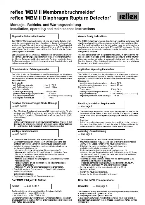
reflex ’MBM II Membranbruchmelder’reflex ’MBM II Diaphragm Rupture Detector’Montage-, Betriebs- und WartungsanleitungInstallation, operating and maintenance instructionsAllgemeine SicherheitshinweiseDer ’MBM II’ Membranbruchmelder ist eine elektrische Schalteinrich-tung, die nur entsprechend den Hinweisen in dieser Anleitung einge-setzt werden darf. Die elektrische Verkabelung und der Anschluss sind von einem Fachmann nach dem gültigen EVU und VDE Vorschriften auszuführen. Vor den Arbeiten an elektrischen Bauteilen ist die Anlage spannungsfrei zu schalten.Das Missachten dieser Anleitung, insbesondere der Sicherheitshinwei-se, kann zur Zerstörung und Defekten am ’MBM II’ Membranbruchmel-der führen, Personen gefährden sowie die Funktion beeinträchtigen. Bei Zuwiderhandlung sind jegliche Ansprüche auf Gewährleistung und Haftung ausgeschlossen.Montage, Inbetriebnahme → auch Seite 2– Die Anschlüsse A1 und A2 sind spannungsfrei geschaltet.– Elektrodenrelais (3) an Wand o. ä. in unmittelbarer Nähe des Gefäßes befestigen. Vorher ist das Gehäuse abzuschrauben.– Kabelverbindungen herstellen, es stehen 4 Kabeleingänge zur Verfügung (Kabel bauseits).Liefergrenze Reflex = Klemmleiste Elektrodenrelais (3)- Klemme Min. mit Stecker 2.2 der Eletrode (2) verbinden. Dazu Stecker 2.2 abziehen, Kabel einstecken und vorher gelöste Schraube im Stecker 2.2 festziehen.- Klemme Max. (Masse) mit Erdungsblech (2.1) verbinden, vorher Kabel abisolieren.- Falls gewünscht, an die Klemmen 11, 12, 14 potenzialfreien Ausgang anschließen.- Klemmen A1 und A2 für Eingangsspannung anschließen.– Empfindlichkeit am Potenziometer (3.3) auf 20 k Ω einstellen (= Werkseinstellung).– Gehäuse anschrauben.– Zuleitungen A1 und A2 mit Spannung versorgen.Der ’MBM II’ ist jetzt in Betrieb.Betrieb → auch Seite 2Der Betrieb ist nur mit angeschraubtem Gehäuse statthaft.– Normalbetrieb : grüne LED leuchtet – Membranbruch : gelbe LED leuchtetMembranbruch kann zu vollständigem Funktionsausfall des Membran-Druckausdehnungsgefäßes führen. Bitte verständigen Sie umgehend Ihren Reflex-Servicedienst.Funktion, Voraussetzungen für die Montage → auch Seite 2– Das Membran-Druckausdehnungsgefäß muss werksseitig für die Montage des ’MBM II’ vorbereitet sein und im unteren Drittel eine Muffe Rp 1/2 (1) besitzen. Ein nachträgliches Einschweißen der Muffe ist unzulässig.– Funktion:Im Falle von Membranbruch wird durch eindringendes Wasser in den Gasraum der elektrische Kontakt zwischen Masse (Erdungsblech 2.1) und Stecker (2.2) hergestellt und ein Signal ausgelöst.Einsatzbereiche, BetriebsparameterDer ’MBM II’ wird zur Signalisierung von Membranbruch bei Membran-Druckausdehungsgefäßen in Heizungs-, Kühl- und Trinkwassersyste-men eingesetzt. Er besteht im wesentlichen aus der Elektrode und dem Elektrodenrelais.Elektrode (2)zul. Betriebstemperatur : t max ≤ 70°C zul. Betriebsüberdruck : p max ≤ 25 bar Elektrodenrelais (3)Spannungsversorgung : 230 V, 50 Hz potenzialfreier Ausgang (Wechsler) : ≤ 250 V Ansprechempfindlichkeit : 5 - 100 k Ω (am Poti einstellbar) Schutzgrad im Gehäuse : IP 65General Safety InstructionsThe ’MBM II’ diaphragm rupture detector is an electrical switchgear that may be exclusively used in accordance with the notes contained her-ein. The electrical cabling and the connection must be performed by a specialist according to the applicable EVU and VDE provisions. Prior to performing any work on electrical components, it must be ensured that the system is not alive.The non-compliance with the present instruction, in particular the no-tes on safety, may lead to the destruction and faults of the ’MBM II’ diaphragm rupture detector, to personal injuries and may affect the function. In case of the violation of such instruction, any and all claims for warranty and liability are excluded.Assembly, Commissioning → also page 2– The connections A1 and A2 are connected off-circuit.– Mount the electrode relay (3) on a wall or similar in the immediate vicinity of the vessel. Unscrew the housing in advance.– Establish the cable connections. Four cable inputs are available (cables to be provided on site).Reflex delivery limit = terminal block electrode relay (3)- Connect the min. terminal with plug 2.2 of the electrode (2). T o do so, disconnect plug 2.2, insert the cable, and fasten the previously released screw in the plug 2.2.- Connect the max. terminal (mass) with the earthing plate (2.1), strip the cable insulation in advance.- If desired, connect a floating output to the terminals 11, 12, 14. - Connect the terminals A1 and A2 for the input voltage.– Set the sensitivity on the potentiometer (3.3) to 20 k Ω (= factory setting).– Fasten the housing with screws.– Supply the feed lines A1 and A2 with power.Now, the ’MBM II’ is operational.Operation → also page 2The operation is only admissible if the housing is fastened with screws.– Regular operation : green LED is on – Diaphragm rupture : yellow LED is onA diaphragm rupture can result in the complete functional failure of the diaphragm expansion vessel. Please contact your Reflex service immediately.Function, Installation Requirements → also page 2– The diaphragm expansion vessel must be prepared on site for the installation of the ’MBM II’ and must provide of a Rp 1/2 (1) sleeve in the lower third. A subsequent welding of the sleeve is not admis-sible.– Function:In the event of a diaphragm rupture, the electrical contact between the mass (earthing plate 2.1) and the plug (2.2) is established by water penetrating into the gas space, and a signal is triggered.Application, Operating ParametersThe ’MBM II’ is used for the signalling of a diaphragm rupture ofdiaphragm expansion vessels in heating, cooling, and drinking water systems. It mainly consists of the electrode and the electrode relay.Electrode (2)permiss. operating temperature : t max ≤ 70°C permiss. operating excess pres. : p max ≤ 25 bar Electrode relay (3) Power supply : 230 V, 50 Hz floating output (change-over cont.) : ≤ 250 V response sensitivity : 5 - 100 k Ω (adjustable on potentiometer ) degree of protection in the housing : IP 65reflex ’MBM II Membranbruchmelder’reflex ’MBM II Diaphragm Rupture Detector’S I 0216A / 03 - 06 T e c h n i s c h e Än d e r u n g e n v o r b e h a l t e n T e c h n i c a l d e t a i l s s u b j e c t t o m o d i f i c a t i o nMontage- und LieferübersichtOverview of the Installation and Delivery1 Rp 1/2 sleeve on the vessel2 Electrode , with vessels which have a constant pre-set pressure sealed into the vessel sleeve (1) in the factory, otherwise enclosed for on-site installation. 2.1 Earthing plate 2.2 detachable plug2.3 Angle3 Electrode relay in the housing3.1 green LED, is on during the regular operation 3.2 yellow LED, is on during in case of a diaphragm rupture3.3 Potentiometer to adjust the response sensitivity 4 Transport protection for the electrode (2), channel section made of foamed material,remove prior to the installationKonformitätserklärungDas Elektrodenrelais ist für den Einsatz im ’MBM II’ geeignet und wird folgenden Normen gerecht:VDE 0435, VDE 0609, VDE 0110, VBG 4, IEC 158-1,IEC 255-0-20, IEC 255-3 & 6, IEC 255-8 & 17, IEC 255-22-1, IEC 255-22-2, IEC 255-5, IEC 801-4, IEC 67.1.5 1 & 18, DIN 46277, IEC 529, DIN 40050, NFC 20010 Zulassungen: UL, CSA Declaration of ConformityThe electrode relay is suited for the deployment in the ’MBM II’ and complies with the following standards:VDE 0435, VDE 0609, VDE 0110, VBG 4, IEC 158-1,IEC 255-0-20, IEC 255-3 & 6, IEC 255-8 & 17, IEC 255-22-1, IEC 255-22-2, IEC 255-5, IEC 801-4, IEC 67.1.5 1 & 18, DIN 46277, IEC 529, DIN 40050, NFC 20010 Approvals:UL, CSANetwork 230 V, 50 Hz6,4 mm x 2,5 mm, NSGAFÖU (bauseits) 6.4 mm x 2.5 mm, NSGAFÖU (on site)2.22.32.141 Muffe Rp 1/2 am Gefäß2 Elektrode , bei Gefäßen mit konstantem Vordruck werksseitig in Behältermuffe (1) eingedichtet, ansonsten beigelegt zur bauseitigen Montage. 2.1 Erdungsblech2.2 abziehbarer Stecker 2.3 Winkel3 Elektrodenrelais im Gehäuse3.1 grüne LED, leuchtet bei Normalbetrieb 3.2 gelbe LED, leuchtet bei Membranbruch 3.3 Potenziometer zur Einstellung der Ansprechempfindlichkeit4 Transportschutz für Elektrode (2), U-Profil aus Schaumstoff, vor derMontage abnehmen33.33.23.1Reflex Winkelmann GmbH + Co. KG Gersteinstraße 1959227 AhlenTelefon: +49 23 82 / 70 69-0Telefax: +49 23 82 / 70 69-588www.reflex.de。
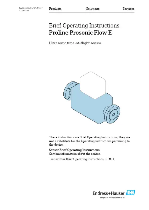
Products Solutions ServicesBrief Operating Instructions Proline Prosonic Flow EUltrasonic time-of-flight sensorThese instructions are Brief Operating Instructions; they are not a substitute for the Operating Instructions pertaining to the device.Sensor Brief Operating Instructions Contain information about the sensor.Transmitter Brief Operating Instructions → 3.KA01329D/06/EN/01.1771382750Proline Prosonic Flow E2Endress+HauserProline Prosonic Flow E Brief Operating Instructions for the deviceEndress+Hauser 3Brief Operating Instructions for the deviceThe device consists of a transmitter and a sensor.The process of commissioning these two components is described in two separate manuals:•Sensor Brief Operating Instructions•Transmitter Brief Operating InstructionsPlease refer to both Brief Operating Instructions when commissioning the device as the contents of the manuals complement one another:Sensor Brief Operating InstructionsThe Sensor Brief Operating Instructions are aimed at specialists with responsibility for installing the measuring device.•Incoming acceptance and product identification •Storage and transport •InstallationTransmitter Brief Operating InstructionsThe Transmitter Brief Operating Instructions are aimed at specialists with responsibility for commissioning, configuring and parameterizing the measuring device (until the first measured value).•Product description •Installation•Electrical connection •Operation options •System integration •Commissioning•Diagnostic informationAdditional device documentationThese Brief Operating Instructions are the Sensor Brief Operating Instructions .The "Transmitter Brief Operating Instructions" are available via:•Internet: /deviceviewer•Smart phone/tablet: Endress+Hauser Operations AppDetailed information about the device can be found in the Operating Instructions and the other documentation:•Internet: /deviceviewer•Smart phone/tablet: Endress+Hauser Operations AppTable of contents Proline Prosonic Flow E4Endress+HauserTable of contents1Document information (5)1.1Symbols used (5)2Basic safety instructions (6)2.1Requirements for the personnel ............................................................62.2Designated use ........................................................................72.3Workplace safety ......................................................................82.4Operational safety ......................................................................82.5Product safety .........................................................................82.6IT security ............................................................................83Incoming acceptance and product identification (9)3.1Incoming acceptance ....................................................................93.2Product identification (10)4Storage and transport (10)4.1Storage conditions ....................................................................104.2Transporting the product (10)5Installation (12)5.1Installation conditions ..................................................................125.2Mounting the measuring device ...........................................................165.3Post-mounting check (17)6Disposal (17)6.1Removing the measuring device ..........................................................176.2Disposing of the measuring device (17)Proline Prosonic Flow E Document information 1 Document information1.1 Symbols used1.1.1 Safety symbols1.1.2 Symbols for certain types of information1.1.3 Electrical symbolsEndress+Hauser5Basic safety instructions Proline Prosonic Flow E6Endress+Hauser1.1.4 Tool symbols1.1.5 Symbols in graphics2Basic safety instructions2.1Requirements for the personnelThe personnel must fulfill the following requirements for its tasks:‣Trained, qualified specialists must have a relevant qualification for this specific function and task.‣Are authorized by the plant owner/operator.‣Are familiar with federal/national regulations.‣Before starting work, read and understand the instructions in the manual andsupplementary documentation as well as the certificates (depending on the application).‣Follow instructions and comply with basic conditions.Proline Prosonic Flow E Basic safety instructionsEndress+Hauser72.2 Designated useApplication and mediaThe measuring device described in these Brief Operating Instructions is intended only for flow measurement of gases.Depending on the version ordered, the measuring device can also measure potentially explosive, flammable, poisonous and oxidizing media.Measuring devices for use in hazardous areas, in hygienic applications or where there is an increased risk due to process pressure, are labeled accordingly on the nameplate.To ensure that the measuring device remains in proper condition for the operation time:‣Keep within the specified pressure and temperature range.‣Only use the measuring device in full compliance with the data on the nameplate and the general conditions listed in the Operating Instructions and supplementary documentation.‣Based on the nameplate, check whether the ordered device is permitted for the intended use in the hazardous area (e.g. explosion protection, pressure vessel safety).‣Use the measuring device only for media to which the process-wetted materials are sufficiently resistant.‣If the measuring device is not operated at atmospheric temperature, compliance with the relevant basic conditions specified in the associated device documentation is absolutely essential: "Documentation" section.‣Protect the measuring device permanently against corrosion from environmental influences.Incorrect useNon-designated use can compromise safety. The manufacturer is not liable for damage caused by improper or non-designated use.L WARNINGDanger of breakage due to corrosive or abrasive fluids!‣Verify the compatibility of the process fluid with the sensor material.‣Ensure the resistance of all fluid-wetted materials in the process.‣Keep within the specified pressure and temperature range.Verification for borderline cases:‣For special fluids and fluids for cleaning, Endress+Hauser is glad to provide assistance in verifying the corrosion resistance of fluid-wetted materials, but does not accept any warranty or liability as minute changes in the temperature, concentration or level of contamination in the process can alter the corrosion resistance properties.Residual risksL WARNINGThe electronics and the medium may cause the surfaces to heat up. This presents a burn hazard!‣For elevated fluid temperatures, ensure protection against contact to prevent burns.Basic safety instructions Proline Prosonic Flow E8Endress+Hauser2.3 Workplace safetyFor work on and with the device:‣Wear the required personal protective equipment according to federal/national regulations.For welding work on the piping:‣Do not ground the welding unit via the measuring device.If working on and with the device with wet hands:‣Due to the increased risk of electric shock, gloves must be worn.2.4 Operational safetyRisk of injury!‣Operate the device in proper technical condition and fail-safe condition only.‣The operator is responsible for interference-free operation of the device.2.5 Product safetyThis measuring device is designed in accordance with good engineering practice to meet state-of-the-art safety requirements, has been tested, and left the factory in a condition in which it is safe to operate.It meets general safety standards and legal requirements. It also complies with the EUdirectives listed in the device-specific EU Declaration of Conformity. Endress+Hauser confirms this by affixing the CE mark to the device.2.6 IT securityWe only provide a warranty if the device is installed and used as described in the Operating Instructions. The device is equipped with security mechanisms to protect it against any inadvertent changes to the device settings.IT security measures in line with operators' security standards and designed to provide additional protection for the device and device data transfer must be implemented by the operators themselves.Proline Prosonic Flow E Incoming acceptance and product identificationEndress+Hauser93Incoming acceptance and product identification3.1Incoming acceptanceA0028673Are the order codes on the delivery note (1)and the product sticker(2) identical?A0028673Are the goods undamaged?A0028673Do the nameplate data match the ordering information on the delivery note?A0028673Is the CD-ROM with the TechnicalDocumentation (depends on deviceversion) and documents present?•If one of the conditions is not satisfied, contact your Endress+Hauser Sales Center.•Depending on the device version, the CD-ROM might not be part of the delivery! The Technical Documentation is available via the Internet or via the Endress+Hauser Operations App .Storage and transport Proline Prosonic Flow E10Endress+Hauser3.2 Product identificationThe following options are available for identification of the measuring device:•Nameplate specifications•Order code with breakdown of the device features on the delivery note •Enter serial numbers from nameplates in W@M Device Viewer(/deviceviewer ): All information about the measuring device is displayed.•Enter the serial number from the nameplates into the Endress+Hauser Operations App or scan the 2-D matrix code (QR code) on the nameplate with the Endress+Hauser Operations App : all the information for the measuring device is displayed.1Example of a nameplate 1Order code2Serial number (Ser. no.)3Extended order code (Ext. ord. cd.)42-D matrix code (QR code)For detailed information on the breakdown of the specifications on the nameplate, see the Operating Instructions for the device .4Storage and transport4.1Storage conditionsObserve the following notes for storage:‣Store in the original packaging to ensure protection from shock.‣Do not remove protective covers or protective caps installed on process connections. They prevent mechanical damage to the sealing surfaces and contamination in the measuring tube.‣Protect from direct sunlight to avoid unacceptably high surface temperatures.‣Store in a dry and dust-free place.‣Do not store outdoors.4.2 Transporting the productTransport the measuring device to the measuring point in the original packaging.Proline Prosonic Flow E Storage and transportEndress+Hauser11Do not remove protective covers or caps installed on process connections. They prevent mechanical damage to the sealing surfaces and contamination in the measuring tube.4.2.1 Measuring devices without lifting lugsL WARNINGCenter of gravity of the measuring device is higher than the suspension points of the webbing slings.Risk of injury if the measuring device slips.‣Secure the measuring device against slipping or turning.‣Observe the weight specified on the packaging (stick-on label).4.2.2 Measuring devices with lifting lugsL CAUTIONSpecial transportation instructions for devices with lifting lugs ‣Only use the lifting lugs fitted on the device or flanges to transport the device.‣The device must always be secured at two lifting lugs at least.4.2.3 Transporting with a fork liftIf transporting in wood crates, the floor structure enables the crates to be lifted lengthwise or at both sides using a forklift.Installation Proline Prosonic Flow E 12Endress+Hauser5Installation 5.1 Installation conditionsNo special measures such as supports are necessary. External forces are absorbed by the construction of the device.5.1.1 Mounting positionMounting locationOrientationThe direction of the arrow on the nameplate helps you to install the sensor according to theflow direction.Install the measuring device in a parallel plane free of external mechanical stress.Proline Prosonic Flow E InstallationEndress+Hauser 13Inlet and outlet runsIf possible, the sensor should be installed upstream from valves, T-pieces, elbows etc. To attain the specified level of accuracy of the measuring device, the below mentioned inlet and outlet runs must be maintained at minimum. If there are several flow disturbances present, the longest specified inlet run must be maintained.For the dimensions and installation lengths of the device, see the "Technical Information"document, "Mechanical construction" section.Installation Proline Prosonic Flow E2Minimum inlet and outlet runs with various flow obstructions190 ° elbow or T-section2Pump3 2 × 90 ° elbow, 3-dimensional4Control valveOutlet runs when installing external devicesIf installing an external device, observe the specified distance.PT Pressure5.1.2 Requirements from environment and processAmbient temperature rangeTransmitter•Prosonic Flow E 100: –25 to +60 °C (–13 to +140 °F)•Prosonic Flow E Heat: –25 to +55 °C (–13 to +131 °F) as per EN 1434environmental class BLocal display Prosonic Flow E 100: –20 to +60 °C (–4 to +140 °F), readability of the displaymay be impaired at temperatures outside the temperature range. Sensor•Prosonic Flow E 100: –25 to +60 °C (–13 to +140 °F)•Prosonic Flow E Heat: –25 to +55 °C (–13 to +131 °F) as per EN 1434environmental class B14Endress+HauserProline Prosonic Flow E Installation Endress+Hauser 15‣If operating outdoors:Avoid direct sunlight, particularly in warm climatic regions.System pressureIt is important that cavitation does not occur, or that gases entrained in the liquids do not outgas. This is prevented by means of a sufficiently high system pressure.For this reason, the following mounting locations are recommended:•At the lowest point in a vertical pipe •Downstream from pumps (no danger of vacuum)Thermal insulationIn the case of some fluids, it is important to keep the heat radiated from the sensor to the transmitter to a low level. A wide range of materials can be used for the required insulation.NOTICEElectronics overheating on account of thermal insulation!‣Observe maximum permitted insulation height of the transmitter neck so that the transmitter head is completely free.tMaximum insulation thickness 2 cm (0.79 in)a Minimum distance from transmitter to insulationInstallation Proline Prosonic Flow E16Endress+Hauser5.2Mounting the measuring device 5.2.1 Required toolsFor transmitter•For turning the transmitter housing: Open-ended wrench8 mm •For opening the securing clamps: Allen key3 mm •For turning the transmitter housing: Open-ended wrench8 mm •For opening the securing clamps: Allen key3 mmFor sensorFor flanges and other process connections: Corresponding mounting tools5.2.2 Preparing the measuring device 1.Remove all remaining transport packaging.2.Remove any protective covers or protective caps present from the sensor.3.Remove stick-on label on the electronics compartment cover.5.2.3 Mounting the measuring device L WARNINGDanger due to improper process sealing!‣Ensure that the inside diameters of the gaskets are greater than or equal to that of the process connections and piping.‣Ensure that the gaskets are clean and undamaged.‣Install the gaskets correctly.1.Ensure that the direction of the arrow on the sensor matches the flow direction of the medium.2.Install the measuring device or turn the transmitter housing so that the cable entries do not point upwards.Proline Prosonic Flow E DisposalEndress+Hauser 175.3 Post-mounting check Is the device undamaged (visual inspection)?Does the measuring device conform to the measuring point specifications?For example:•Process temperature•Process pressure (refer to the section on "Pressure-temperature ratings" in the "Technical Information"document on the CD-ROM provided)•Ambient temperature range•Measuring rangeHas the correct orientation for the sensor been selected → 12?•According to sensor type•According to medium temperature•According to medium properties (outgassing, with entrained solids)Does the arrow on the sensor match the direction of flow of the medium through the piping → 12?Are the measuring point identification and labeling correct (visual inspection)?Is the device adequately protected from precipitation and direct sunlight?Are the securing screw and securing clamp tightened securely? 6Disposal 6.1Removing the measuring device 1.Switch off the device.L WARNINGDanger to persons from process conditions.‣Beware of hazardous process conditions such as pressure in the measuring device, high temperatures or aggressive fluids.2.Carry out the mounting and connection steps from the "Mounting the measuring device"and "Connecting the measuring device" sections in reverse order. Observe the safety instructions.6.2 Disposing of the measuring deviceL WARNINGDanger to personnel and environment from fluids that are hazardous to health.‣Ensure that the measuring device and all cavities are free of fluid residues that are hazardous to health or the environment, e.g. substances that have permeated into crevices or diffused through plastic.Disposal Proline Prosonic Flow E 18Endress+HauserObserve the following notes during disposal:‣Observe valid federal/national regulations.‣Ensure proper separation and reuse of the device components.。
XA00643F-A/00/B2/01.1171158144Safety InstructionsLevelflexFMP54/56/57PROFIBUS PAZone 20/21DIP A20/21 T A , T* IP66en -Document: XA00643F-ASafety instructions for electrical apparatus for explosion-hazardous areas Èä3zh -文档:XA00643F-A爆炸环境中电气仪表的安全指南Èä9Levelflex FMP54/56/57XA00643F-A 2Endress+HauserXA00643F-A Levelflex FMP54/56/57LevelflexFMP54/56/57PROFIBUS PATable of ContentsAssociated documentation . . . . . . . . . . . . . . . . . . . . . . . . . . . . . . . . . . . . . . . . . . . . . . . . 4Supplementary documentation . . . . . . . . . . . . . . . . . . . . . . . . . . . . . . . . . . . . . . . . . . . . . 4Manufacturer's certificates . . . . . . . . . . . . . . . . . . . . . . . . . . . . . . . . . . . . . . . . . . . . . . . . 4Extended order code . . . . . . . . . . . . . . . . . . . . . . . . . . . . . . . . . . . . . . . . . . . . . . . . . . . . 4Safety instructions: General . . . . . . . . . . . . . . . . . . . . . . . . . . . . . . . . . . . . . . . . . . . . . . . 6Safety instructions: Special conditions . . . . . . . . . . . . . . . . . . . . . . . . . . . . . . . . . . . . . . . . 6Safety instructions: Installation . . . . . . . . . . . . . . . . . . . . . . . . . . . . . . . . . . . . . . . . . . . . . 6Temperature tables . . . . . . . . . . . . . . . . . . . . . . . . . . . . . . . . . . . . . . . . . . . . . . . . . . . . . 7Connection data . . . . . . . . . . . . . . . . . . . . . . . . . . . . . . . . . . . . . . . . . . . . . . . . . . . . . . . 7 Endress+Hauser3Levelflex FMP54/56/57XA00643F-A4Endress+HauserAssociated documentation This document is an integral part of the following Operating Instructions:BA01006F/00 (FMP54), BA01009F/00 (FMP56/57)The Operating Instructions pertaining to the device apply.Supplementary documentation Explosion-protection brochure:CP021Z/00The Explosion-protection brochure is available:•In the download area of the Endress+Hauser website: → Download → Advanced → Documentation Code: CP021Z•On the CD for devices with CD-based documentationManufacturer's certificates NEPSI Declaration of Conformity Certificate number:GYJ11.1553XAffixing the certificate number certifies conformity with the standards:•GB3836.1-2010•GB12476.1-2000•GB12476.4-2010, with the following standard under :-IEC61241-0:2004Extended order codeThe extended order code is indicated on the nameplate, which is affixed to the device in such a way that it is clearly visible. Additional information about the nameplate is provided in the associated Operating Instructions.Structure of the extended order code •Basic specificationsThe features that are absolutely essential for the device (mandatory features) are specified in the basic specifications. The number of positions depends on the number of features available. The selected option of a feature can consist of several positions.•Optional specificationsThe optional specifications describe additional features for the device (optional features). The number of positions depends on the number of features available.The features have a 2-digit structure to aid identification (e.g. JA). The first digit (ID) stands for the feature group and consists of a number or a letter (e.g. J = test, certificate).The second digit constitutes the value that stands for the feature within the group (e.g. A = 3.1 material (wetted parts), inspection certificate).More detailed information about the device is provided in the following tables. These tables describe the individual positions and IDs in the extended order code which are relevant to hazardous locations.FMP5x-*************+A*B*C*D*E*F*G*..------------------------------------------------------------------------Device typeBasic specificationsOptional specifications* =PlaceholderAt this position, an option (number or letter) selected from the specification is displayed instead of the placeholders.XA00643F-A Levelflex FMP54/56/57Endress+Hauser 5Device type: FMP54, FMP56, FMP57Basic specificationsOptional specificationsPosition Selected option Description1, 2ApprovalNF Zone 20/21DIP A20/21 T A , T* IP663Power Supply; Output G 2-wire, PROFIBUS PA4Display; Operation A C Without LCD, via communicationLCD SD02, push button + data backup function 5HousingB CDual compartment, 316L (GT18)Dual compartment, Alu coated (GT20)9, 10SealAB (only FMP56)A4 (only FMP57)B3 (only FMP56/57)D1 (only FMP54)D2 (only FMP54)Viton,–30...120 °C Viton,–30...150 °C EPDM, –40...120 °CGraphite, –196...280 °C (XT)Graphite, –196...450 °C (HT)ID Selected option DescriptionMxProbe DesignMBME (only FMP54)Sensor remote, 3 m/9 ft cable, detachable + mounting bracketCoax ground tube multiple punchedLevelflex FMP54/56/57XA00643F-A6Endress+HauserSafety instructions:General•Staff must meet the following conditions for mounting, electrical installation, commissioning and maintenance of the device:-Be suitably qualified for their role and the tasks they perform -Be trained in explosion protection -Be familiar with national regulations•For installation, use and maintenance of the device, users must also observe the requirements stated in the Operating Instructions and the standards:-GB50257-1996: "Code for construction and acceptance of electric device for explosion atmospheres and fire hazard electrical equipment installation engineering".-GB15577-2007: "Safety regulations for dust explosive prevention and protection".-GB12476.2-2006: "Electrical apparatus for use in the presence of combustible dust,Part 1-2: Electrical apparatus protected by enclosures and surface temperature limitation - Selection, installation and maintenance".•Install the device according to the manufacturer's instructions and national regulations.•Do not operate the device outside the specified electrical, thermal and mechanical parameters.•Only use the device in media to which the wetted materials have sufficient durability.•Refer to the temperature tables for the relationship between the permitted ambient temperature for the sensor and/or transmitter, depending on the range of application, and the temperature class.•Modifications to the device can affect the explosion protection and must be carried out by staff authorized to perform such work by Endress+Hauser.•When replacing the probe electronics or opening the connection between the remote cable and the probe, a jumper plug must be used or a short-circuit must be established between the probe contact and the potential equalization conductor to avoid electrostatically charging the probe.•After mounting and connecting the probe, ingress protection of the housing must be at least IP66. Perform the following to achieve the degree of protection: - Screw the cover tight.-Mount the cable entry correctly.Safety instructions:Special conditions Permitted ambient temperature range at the electronics housing: –40 °C ≤ T a ≤ +80 °C.Observe the information in the temperature tables.Safety instructions:Installationå 1A Zone 211Tank; Zone 20, Zone 212Electronics compartment Ex iaD; Electronic insert 3Connection compartment DIP A214Power supply5Potential equalization line 6Potential equalizationXA00643F-A Levelflex FMP54/56/57Endress+Hauser 7•In the case of process connections made of polymeric material or with polymeric coatings, avoid electrostatic charging of the plastic surfaces.•After aligning (rotating) the housing, retighten the fixing screw (see Operating Instructions).•When mounting the device:-Exclude any mechanical damage or friction during the application. -Pay particular attention to flow conditions and tank fittings.•Continuous service temperature of the connecting cable: –40 to ≥ +85 °C; in accordance with the range of service temperature taking into account additional influences of the process conditions (T a,min and T a,max +20 K).•In the event of additional or alternative special varnishing on the housing or other metal parts: -Observe the danger of electrostatic charging and discharge. -Do not rub surfaces with a dry cloth.•Only use certified cable entries or sealing plugs.The metal sealing plugs supplied meet this requirement.•Before operation:-Screw in the cover all the way.-Tighten the securing clamp on the cover.Intrinsic safety•The device can be connected to the Endress+Hauser FXA291 service tool: refer to the Operating Instructions.Temperature tables Èä15Connection dataBasic specification, Position 1, 2 (Approval) = NF Connection compartment DIP A21Electronics compartment Ex i Service interface (CDI)Taking the following values into consideration, the device can be connected to the Endress+Hauser FXA291 service tool or a similar interface:Basic specification, Position 3 (Power Supply; Output) = G TRC [07]Terminal 1 (+), 2 (–)Terminal 3 (+), 4 (–)Power supply:Output PFS:U N = 32 V DC I max = 25 mA U m = 250 V ACU N = 35 V DC I n = 70 mA U m = 250 V ACService interface U i = 7.3 Veffective inner inductance L i = negligible effective inner capacitance C i = negligible U o = 7.3 V I o = 100 mA P o = 160 mWpermitted outer inductance L o = negligible permitted outer capacitance C o = negligibleLevelflex FMP54/56/57XA00643F-A 8Endress+HauserXA00643F-A Levelflex FMP54/56/57LevelflexFMP54/56/57PROFIBUS PA目录相关资料 . . . . . . . . . . . . . . . . . . . . . . . . . . . . . . . . . . . . . . . . . . . . . . . . . . . . . . . . . . . . 10辅助文档 . . . . . . . . . . . . . . . . . . . . . . . . . . . . . . . . . . . . . . . . . . . . . . . . . . . . . . . . . . . . 10制造商证书 . . . . . . . . . . . . . . . . . . . . . . . . . . . . . . . . . . . . . . . . . . . . . . . . . . . . . . . . . . 10扩展订货号 . . . . . . . . . . . . . . . . . . . . . . . . . . . . . . . . . . . . . . . . . . . . . . . . . . . . . . . . . . 10安全指南:概述 . . . . . . . . . . . . . . . . . . . . . . . . . . . . . . . . . . . . . . . . . . . . . . . . . . . . . . 12安全指南:特殊条件 . . . . . . . . . . . . . . . . . . . . . . . . . . . . . . . . . . . . . . . . . . . . . . . . . . . 12安全指南:安装 . . . . . . . . . . . . . . . . . . . . . . . . . . . . . . . . . . . . . . . . . . . . . . . . . . . . . . 12温度表 . . . . . . . . . . . . . . . . . . . . . . . . . . . . . . . . . . . . . . . . . . . . . . . . . . . . . . . . . . . . . . 13连接数据 . . . . . . . . . . . . . . . . . . . . . . . . . . . . . . . . . . . . . . . . . . . . . . . . . . . . . . . . . . . . 13 Endress+Hauser9Levelflex FMP54/56/57XA00643F-A相关资料本文档是下列操作手册的组成部分:BA01006F/00 (FMP54), BA01009F/00 (FMP56/57)应遵守设备的操作手册。

FU TillerOperation Manual ContentsPreface (3)Revision History (4)Glossary (5)Abbreviations (5)Definitions (5)Safety Information (6)Warranty (7)Introduction (8)Enabling FU control (9)Control allowed/not allowed (10)Control handover (11)Take control (11)Release/take control (11)Steering (11)Alarm handling (12)Dimming (12)Alarm speaker and lamp test (13)PrefaceThe Alphatron AlphaPilot MFM system is a type approved heading control system, designed to fit vessels of any size, including high speed crafts.The FU Tiller is part of the AlphaPilot MFM system and is used for steering in manual FU steering mode.•Thoroughly read this operation manual before operating the equipment.•We recommend keeping this manual nearby the equipment to ensure ready access to it.GlossaryThe glossary contains a list of abbreviations and a list of definitions.AbbreviationsAbbreviations as used in this manual are explained in the table below.DefinitionsThe meaning of standard definitions as used in this manual are explained in the table below.Safety InformationThe signal words DANGER, WARNING and CAUTION used in this manual indicate the degree of hazard that may be encountered by the user. These words are defined as follows:DANGER Indicates a hazardous situation which, if not avoided, will result in deathor serious injury. This signal word is limited to the most extremesituations.WARNING Indicates a hazardous situation which, if not avoided, could result in deathor serious injury.CAUTION Indicates a hazardous situation which, if not avoided, could result in minoror moderate injury.The signal word NOTICE used in this manual indicates information considered important but not related to injury. It is typically used to prevent damage to equipment or property.To safely operate this system, the following DANGERS, WARNINGS, and CAUTIONS must be adhered to. Failure to comply with the precautions or with specific dangers, warnings, and cautions elsewhere in this manual violates safety standards of design, manufacture, and intended use of the equipment. ALPHATRON MARINE assumes no liability for the customer's failure to comply with these requirements.WARNING Do not disassemble or modify the equipment. Otherwise, it may cause a fire, or you may suffer an electrical shock.WARNING Immediately turn off the power and disconnect the power supply cable if the equipment is generating any smoke or odour or is overheated. Immediately inform your local service agent of the symptom to have it repaired. Prolonged equipment operation under such a condition can cause a fire or electric shock.WARNING Do not place a container containing liquid on the equipment. Otherwise, it may cause a fire, or you may suffer an electrical shock if knocked over.WARNING When unplugging the instrument, be sure to remove the cord terminal correctly. If the cord is pulled, the cord may get damaged resulting in a fire or an electrical shock.WarrantyTo not to adversely affect the warranty, the following notices must be adhered to.NOTICE Operating personnel must not remove equipment covers. Only personnel trained and certified by ALPHATRON MARINE must make component replacement and internal adjustment.NOTICE Do not disassemble or modify the equipment. Failure to observe this instruction may cause equipment failure, and it will void the warranty.NOTICE Any modification to this equipment without prior written permission from ALPHATRON MARINE will void the warranty.NOTICE Installation of this product shall only be done by a certified installation company approved by either ALPHATRON MARINE or by an official ALPHATRON MARINE distributor. Acting otherwise will void the warranty.NOTICE This product contains no operator serviceable parts. Service and repair shall only be carried out by personnel trained and certified by ALPHATRON MARINE.NOTICE Do not place a container containing liquid on the equipment. The equipment can be damaged if knocked over.NOTICE When cleaning the surface, do not use any organic solvent such as thinner or benzine. Otherwise, the paint and markings on the surface may get damaged. For cleaning the surface, remove the dust and debris and wipe with a clean dry cloth.IntroductionThe FU Tiller is part of the AlphaPilot MFM system and is used for steering in manual FU steering mode. The FU Tiller is typically used in combination with an AlphaPilot MFM control unit.The FU Tiller has 1 handle and multiple buttons:-The alarm speaker button will illuminate when there is an alarm. The button is used to mute the speakers of the FU Tiller and interconnected modules.-Buttons DIM - and DIM + are used to control the brightness level of the FU Tiller and interconnected modules.-Button FU is used to release/take FU control.-The handle is used to steer (step less control).Figure 1: FU TillerEnabling FU controlPush the button FU to enable FU control*. The control mode indicator FU and handle indicator will illuminate, meaning that FU mode is enabled, and that the handle is enabled.*Note that control must be allowed, see subsection ‘Control allowed/not allowed’ on page 10. Note that another active controller may need to allow control handover first, see su bsection ‘Control handover‘ on page 11.Figure 3: FU mode enabledFigure 2: STBY mode enabledControl allowed/not allowedWhen not in control, the FU Tiller is in standby mode and handle is disabled (the control mode indicator STBY is illuminated and the handle indicator is not illuminated). Button FU is illuminated when allowed to take control (see Figure 4 and Figure 5).FU control is steering in manual FU steering mode; therefore, the Mode Switch must be in position MAN (Mode Switch 3 Pos) or AUTO|MAN (Mode Switch 2 Pos).FU control is not allowed when the Mode Switch is in position NFU (Mode Switch 2 Pos & Mode Switch 3 Pos) or AUTO (Mode Switch 3 Pos)).When a non-illuminated button is pushed, the speaker produces 4 short successive beeps to indicate that the operation is not valid.Figure 4: Enabling FU controlnot allowedFigure 5: Enabling FU controlallowedControl handoverIf applicable, handover of control must be allowed first by the active controller to allow the FU Tiller to take control (i.e. enable FU control).The method for control handover is pre-set during commissioning. Two system settings are possible, namely ‘Take control’ or ‘Release/take control’.Take controlAny controller can take control. Control handover allowance is not applicable.Procedure for FU Tiller:-Push the button FU to enable FU control. Control mode indicator FU and the handle indicator will illuminate, meaning that the FU mode and the handle is enabled.Release/take controlAny controller can take control, only when the active controller allows control handover. Procedure for FU Tiller:-Take controlAllow control handover from the active controller (refer to the respective operation manual for the procedure). Button FU will illuminate to indicate that FU control is allowed. Push the button FU to enable FU control. Control mode indicator FU and the handle indicator willilluminate, meaning that the FU mode and the handle is enabled.-Release controlTo allow control handover to another controller, push the button FU, until control modeindicator FU flashes (this indicates that control handover is allowed).NOTE: The FU Tiller stays in control until control is transferred to another controller.NOTE: Control mode indicator FU keeps flashing until control is transferred to anothercontroller. There is no timeout. The speaker produces 3 short successive beeps with 10seconds interval to indicate that the operation is not finished.NOTE: The FU Tiller goes into standby mode when control is transferred to anothercontroller.SteeringIn FU control, the steering gear will move the rudder as per FU value command (rudder angle). Moving the handle to the neutral position will cause the rudder to move to the centre position. Turning the handle farthest to the left will cause the rudder to move to a predefined maximum rudder angle, turning the handle farthest to the right will cause the rudder to move to the predefined maximum rudder angle in the opposite direction.11 | SteeringAlarm handlingThe alarm speaker button is only illuminated when there is an internal alarm. When an alarm occurs, the alarm speaker button will flash in an uninterrupted sequence, and the speaker will beep in an uninterrupted sequence.Figure 6: AlarmactiveThe alarm speaker can be muted via the alarm speaker button.When the alarm (is read and) acknowledged on the AlphaPilot MFM control unit, then the illumination will be constant, and the speaker will be muted (if not muted already via the FU Tiller). When the alarm is accepted (e.g. problem solved), then the illumination on the alarm speaker button will turn off.DimmingButtons DIM - and DIM + are always illuminated (dimmed to a pre-set brightness level) and control is always allowed.Push the button DIM - or DIM + to simultaneously adjust the brightness level of all indicators on the FU Tiller and interconnected modules.12 | Alarm handlingAlarm speaker and lamp testSimultaneously push and hold button DIM - and DIM + to test the alarm speaker and the indicators; The alarm speaker will beep continuously and all indicators (buttons, control mode indicators, and handle indicator) will illuminate continuously, until the buttons are released.13 | Alarm speaker and lamp test。
Operating instruction Translation of the originalThree-way ball valvepneumatic und manual operationTypes 403x413x423x20K I E S E L M A N N G m b HPaul-Kieselmann-Str. 4-10D - 75438 Knittlingen( +49(0) 7043 371-0 • 7 +49(0) 7043 371-125 www.kieselmann.de•****************** Copyright: © KIESELMANN FLUID PROCESS GROUPKIESELMANN GmbH Table of contents Table of contents1General informations (4)1.1Informations for your safety (4)1.2Marking of security instructions (4)1.3General designated use (4)1.4Personnel (4)1.5Modifications, spare parts, accessories (5)1.6General instructions (5)2Safety instructions (6)2.1Intended use (6)2.2General notes (6)2.3General safety instructions (6)3Delivery, transport and storage (8)3.1Delivery (8)3.2Transport (8)3.3Storage (8)4Specification (9)4.1Modular system (9)5Function and operation (10)5.1Description of function (10)5.2Control system and position indication (11)6Commissioning, service and maintenance (12)6.1Commissioning (12)6.1.1Installation instructions (12)6.1.2General welding guidelines (12)6.1.3ATEX - Guidelines (12)6.2Service (13)6.3Cleaning (13)7Technical data (14)8Disassembly and assembly (15)8.1Disassembly (15)8.2Assembly (16)9Drawings and dimensions (17)9.1Control units (17)9.2Drawings (18)9.3Dimensions (20)10Wearing parts (21)10.1Wear parts kit (21)10.2Spare parts list (22)11Classification (23)11.1Structure of Order Number (23)12Appendix (25)12.1Declaration of incorporation (25)4x3x_TWBV_EN3Operating instruction | KIESELMANN GmbH 1 | General informations 4 / 254x3x_TWBV_EN 1General informations1.1Informations for your safetyWe are pleased that you have decided for a high-class KIESELMANN GmbH product. With correctapplication and adequate maintenance, our products provide long time and reliable operation.Before installation and initiation, please carefully read this instruction manual and the security ad-vices contained in it. This guarantees reliable and safe operation of this product and your plant re-spectively. Please note that an incorrect application of the process components may lead to greatmaterial damages and personal injury.In case of damages caused by non observance of this instruction manual, incorrect initiation, hand-ling or external interference, guarantee and warranty will lapse!Our products are produced, mounted and tested with high diligence. However, if there is still areason for complaint, we will naturally try to give you entire satisfaction within the scope of our war-ranty. We will be at your disposal also after expiration of the warranty. In addition, you will also findall necessary instructions and spare part data for maintenance in this instruction manual. If youdon't want to carry out the maintenance by yourself, our KIESELMANN GmbH - service team willnaturally be at your disposal.1.2Marking of security instructionsHints are available in the chapter "safety instructions" or directly before the respective operation in-struction. The hints are highlighted with a danger symbol and a signal word. Texts beside thesesymbols have to be read and adhered to by all means. Please continue with the text and with thehandling at the valve only afterwards.Symbol Signal wordMeaning DANGER Imminent danger which will result severe personal injury ordeath.WARNING Imminent danger which may result severe personal injury ordeath.CAUTION Dangerous situation which may cause slight personal injury ormaterial damages.NOTICE An harmful situation which may result in damages of the productitself or of adjacent vicinity.INFORMATIONMarks application hints and other information which is particu-larly useful.1.3General designated useThe fitting is designed exclusively for the purposes described below. Using the fitting for purposesother than those mentioned is considered contrary to its designated use. KIESELMANN GmbH can-not be held liable for any damage resulting from such use. The risk of such misuse lies entirely withthe user. The prerequisite for the reliable and safe operation of the fitting is proper transportationand storage as well as competent installation and assembly. Operating the fitting within the limitsof its designated use also involves observing the operating, inspection and maintenance instruc-tions.1.4PersonnelPersonnel entrusted with the operation and maintenance of the tank safety system must have thesuitable qualification to carry out their tasks. They must be informed about possible dangers andmust understand and observe the safety instructions given in the relevant manual. Only allow quali-fied personnel to make electrical connections.KIESELMANN GmbH | Operating instruction General informations | 11.5Modifications, spare parts, accessoriesUnauthorized modifications, additions or conversions which affect the safety of the fitting are notpermitted. Safety devices must not be bypassed, removed or made inactive. Only use original spareparts and accessories recommended by the manufacturer.1.6General instructionsThe user is obliged to operate the fitting only when it is in good working order. In addition to the in-structions given in the operating manual, please observe the relevant accident prevention regula-tions, generally accepted safety regulations, regulations effective in the country of installation,working and safety instructions effective in the user's plant.4x3x_TWBV_EN 5 / 25Operating instruction | KIESELMANN GmbH 2 | Safety instructions 6 / 254x3x_TWBV_EN 2Safety instructions2.1Intended useThe Three way ball valve can be used as multiple way valve in the drinks and food industry, thepharmaceuticals and chem. Industry and the bio-technology sector.2.2General notesTo avoid danger and damage, the fitting must be used in accordance with the safety instructionsand technical data contained in the operating instructions.All data are in line with the current state of development. Subject to change as a result of tech-nical progress.2.3General safety instructionsWARNINGRisk of injury by outflowing mediumDismantling the valve or valve assemblies from the plant can cause injuries.–Medias flowing through the leakage drain outlet are to be drained off without splashing into a discharge arrangement.–Carry the disassembling only if when the plant has been rendered pressure-less and freeof liquid and gas.WARNINGRisk of injury by moving partsDo not grab into the valve when the actuator is pressurized. Limbs can be crushing or amputating.–Remove the control air line before dismantling.–Ensure that the actuator is unpressurized.WARNINGRisk of injury by pre-stressed pressure spring.The pneumatic-mechanical actuator is spring-loaded. When disassembling the actuator, compon-ents that jump out may cause injuries.–Multiturn actuator are maintenance-free and therefore do not need to be opened!WARNINGATEX - GuidelinesIf the valve or the plant is operated in a potentially explosive atmosphere, the valid ATEX directive ofthe EC and the installation instructions in this operating manual must be observed.CAUTIONTo avoid air leaking, only use pneumatic connection parts that have an O-ring seal facing the evensurface.CAUTION Before starting the system, the entire pipeline system must be thoroughly cleaned.KIESELMANN GmbH | Operating instruction Safety instructions | 24x3x_TWBV_EN7 / 25 CAUTION Steps should be taken to ensure that no external forces are exerted on the fitting.Operating instruction | KIESELMANN GmbH 3 | Delivery, transport and storage 8 / 254x3x_TWBV_EN 3Delivery, transport and storage3.1Delivery•Immediately after receipt check the delivery for completeness and transport damages.•Remove the packaging from the product.•Retain packaging material, or expose of according to local regulations.3.2TransportCAUTIONRisk of injury and damage to the productDuring the transport the generally acknowledged rules of technology, the national accident preven-tion regulationsand company internal work and safety regulations must be observed.3.3StorageDamage to the product due to improper storage!Observe storage instructionsavoid a prolonged storageRecommendation for longer storageWe recommend regularly checking the product and the prevailing storage conditions during long storage times.•To avoid damage to seals and bearings,–products up to DN 125 / OD 5 inch should be stored horizontally for maximum 6 months.–products larger than DN 125 / 5 inch, should be stored in the upright position with the actu-ator on top.•Don't store any objects on the products.•Protect the products for wetness, dust and dirt.•The product should be stored in a dry and well ventilated room at a constant temperature (op-timal indoor temperature: 25 C ±5 ; indoor humidity data 70% ±5%).•Protect seals, bearings and plastic parts for UV light and ozone.KIESELMANN GmbH | Operating instruction Specification | 4 4Specification4.1Modular systemHand lever4x3x_TWBV_EN9 / 25Operating instruction | KIESELMANN GmbH 5 | Function and operation 10 / 254x3x_TWBV_EN 5Function and operation5.1Description of functionThe Three way ball valve is a distribution valve with the function of the valve is the opening or clos-ing of several pipes to divert the flow. The possible assembly-line ways in dependence of the stopfunctions linked with it are shown in the table as valve positions.Valve positions L - ball AC BA CB Valve positions T -ball AC B A C B A C BA CB Functional description for valves with manual operationWhen actuating a fitting manually, the respective switching position will be locked in place in the fi-nal position. The desired valve position can be positioned in 90° steps by a rotary movement bymeans of a hand lever strength in a swivelling angle of 360 °.Before operation, unlock the final position lock by lifting the notch lever against the hand lever. Byletting go of the notch lever in the respective final position the spring-loaded notch lever will latchback by itself to the final position lock.Description of function for pneum. valvesBy means of a pneum. multiturn actuator, the valve ball is rotated by a 90° rotary movement.KIESELMANN GmbH | Operating instruction Function and operation | 5Description of function for pneum. valvesThe valve opens and closes by way of a pneum. multiturn actuator with a rotary movement of 90°.normal closed (NC)•pneum. OPERATED •not pneum. OPERATED opens the valvespring force closes the valvenormal open (NO)•pneum. OPERATED •not pneum. OPERATED closes the valvespring force opens the valvedouble acting (DA)•pneum. OPERATED the valve opens or closes according to control5.2Control system and position indicationRetrofitting to end position feedback for manually operated valvesBy replacing the hand lever and the catch disc the valve can be retrofitted for end position feedback (proximity switch).Conversion from manual operation to pneumatic actuationBy a simple retrofitting operation the valve can be converted to pneumatic actuation. The rotary ac-tuator for this purpose is supplied complete with fitting device. The following actuators are avail-able, depending on the desired actuating function.Position indicator with sensor mounting for feedback signal.The actuator is equipped with a proximity switch mounting (sensor mounting) and a position indica-tion. When inductive proximity initiators M 12x1 are installed, the current "Open" or "Shut" position can be interrogated. By screwing the proximity initiator to the limit position the required switching gap for the signal transmission is established.. When the valve is closed the position indication is oriented vertically to the direction of valve passage. When the valve is open it is oriented parallel to the valve passage.Feedback unit -optional-Optionally, modular valve control head systems can be installed to the actuator for reading and ac-tuating valve positions. The standard version is a closed system with SPS or ASI-bus switch-onelectronics, and integrated 3/2-way solenoid valves. For tough operating conditions we recommend employing a high-grade steel cover.6 | Commissioning, service and maintenanceOperating instruction | KIESELMANN GmbH 6Commissioning, service and maintenance6.1Commissioning6.1.1Installation instructionsFor ball valves without leakage outlet, the installation position is without importance.Ball valves with leakage outlet must always be installed vertically to ensure that outflow of leakage,or of cleaning medium, from the valve is such that no residue will remain inside the valve.For valves which are to be welded in on both sides, a releasable connection has to be fitted into thepipework to allow dismounting (maintenance).6.1.2General welding guidelinesSealing elements integrated in weld components must generally be removed prior to welding. Toprevent damage, welding should be undertaken by certified personnel (EN ISO 9606-1). Use the TIG(Tungsten Inert Gas) welding process.CAUTIONDamage and injuries due to high temperature supplyTo avoid a distortion of the components, all welding parts must be welded to stress-relieved.Allow all components to cool before assembling.Damage due to impuritiesImpurities can cause damage to the seals and seals area.Clean inside areas prior to assembly.6.1.3ATEX - GuidelinesFor valves or plants/installations that are operated in the ATEX area, sufficient bonding (grounding)must be ensured (see valid ATEX Guidelines EG).KIESELMANN GmbH | Operating instruction Commissioning, service and maintenance | 66.2ServiceReplacement of sealsTo achieve optimal maintenance cycles, the following points must be observed!–When replacement of seals, all product-contacting seals should be replaced.–Only original spare parts may be installed.Maintenance intervalThe maintenance intervals depend on the operating conditions "temperature, temperature-intervals,medium, cleaning medium, pressure and opening frequency". We recommend replacing the seals 2-year cycle.The user, however should establish appropriate maintenance intervals according to thecondition of the seals.Lubricant recommendationEPDM; HNBR; NBR; FKM; k-flex-Klüber Paraliq GTE703*Silicone-Klüber Sintheso pro AA2*Thread-Interflon Food**) It is only permitted to use approved lubricants, if the respective fitting is used for the produc-tion of food or drink. Please observe the relevant safety data sheets of the manufacturers of lub-ricants.6.3CleaningIn order to ensure continuous flawless function during operation, the surfaces between the valvebody and the ball must be cleaned.Open and close the valve several times from the open position. With an angle of rotation of ≥ 20°,cleaning fluid flows into the area between the ball and casing. A time-dependent actuation in theangle of rotation range 20°-45° makes the cleaning process more efficient. The duration and thenumber of actuations should be adjusted according to the type of dirtying and the degree of dirty-ing.Operating instruction | KIESELMANN GmbH 7 | Technical data7Technical dataModel:Three-way ball valveValve size:DIN: DN 25 - DN 80Inch: DN 1“ - DN 3“Connections:Welded end (S) DIN EN 10357Thread (G) DIN 11851Flange connection (Fl)Clamp connection (Cl)Liner/nut (K/M) DIN11581Temperature range:Ambient (air)+4° to +45°COperating (medium dependent)+0° to +95°CSterilization (SIP 30 min)EPDM +140°CPTFE +130°CNBR +100°CFKM +140°CPressure range:Working pressure:Cleaning pressure:10 bar 3 barLeak rate: A (DIN EN 12266-1)Control air:Control air pressure:5,5 - 8,0 bar Quality of control air:ISO 8573-1 : 2001 quality class 3Materials: (in product contact)Stainless steel: 1.4301 / AISI3041.4404 / AISI316LSurfaces:Ra < 0,8µm e-polishedSealing material:EPDM / PTFENBR / PTFEFKM / PTFEKIESELMANN GmbH | Operating instruction Disassembly and assembly | 8 8Disassembly and assembly8.1DisassemblyAll threaded joint have right-hand thread.Unscrew and remove control air, steam resp. cleaning lines and electrical lines, complete feedback unit or control head.Remove the ball valve completely from the housing.Replacing the housing seals (3), (5), (6), (19)•Unscrew the flange (4) (2x), (17) and (18).•Dismantle the O-rings (5)(2x), (6)(4x), (19)(2x) and thrust collar (3)(4x).•Remove the ball (2) out of the housing (1).Replacing the sealing package (10), (11), (12)Ball valve - manual operationM 1011 9 8 7•Unscrew the screw (20) and remove the hand lever (21).•Unscrew the screw (16) and remove the locking disc (8).•Remove the plain bearing (14) and the pressure spring (13) from the axis (7).•Dismantle the axis (7) with sliding ring (9) downwards.•Take the sealing package (10/11/12) out of the housing (1).Replacing the sealing package (10), (11), (12)Ball valve - pneum. operation•Unscrew the screws (22) and remove the pneum. actuator (26) with the square boss (25).•Unscrew the screws (24) and remove the angle bracket (23).•Remove the plain bearing (14) and the pressure spring (13) from the axis (7).•Dismantle the axis (7) with sliding ring (9) downwards.•Take the sealing package (10/11/12) out of the housing (1).8 | Disassembly and assemblyOperating instruction | KIESELMANN GmbH8.2Assembly•Before installation, thoroughly clean and slightly lubricate mounting areas and running sur-faces.•Assemble in reverse order.Instructions d'installationMount the sealing package (10/11/12) in the sequence shown under view.b) Push the bearing ring (10), the V-rings (11) (3x) and the thrust collar (12) with the mountingsleeve (M) into the limit stop.c) When mounting the ball (2) and the axis (7), regards for exact match from the marks on the axis(7) and the position of the ball (2).d) The mark points (MP) on the switch axis correspond to the respective ball openings.e) Mount the hand lever or the pneumatic actuator according of the valve functions.MPM1011987KIESELMANN GmbH | Operating instruction Drawings and dimensions | 9 9Drawings and dimensions9.1Control units12925,5Ø 105Position indication with sensor mounting (R)•R1 = dog•R1.1 = Straight pin•R2 = Position indication•R3 = O-ring•R4 = Screw•R5 = Sensor mounting•R6 = Cap•R7 = Screw•LA = air supplyOperating instruction | KIESELMANN GmbH 9 | Drawings and dimensions9.2Drawings•Example: Ball valve, T-ball with male part flange1 = Housing2 = Ball (L,T)3a = Thrust collar3b = Filling element4 = Flange5 = O-rings6 = O-rings7 = Axis8 = Locking disc9 = Sliding ring10 = Backup ring11 = V-ring package12 = Thrust collar13 = Pressure spring14 = Sliding ring15 = Straight pin16 = Screw17 = Blind flange18 = Flange19 = O-ring20a = Saucer-head screw20b = Screw21a = Hand lever GFK21b = Hand lever stainlesssteel22 = Screws23 = Holding flange24 = Screws25 = Square boss26 = ActuatorM = Mounting sleeveS = Control headR = Sensor mountingR1 = dogR2 = Position indicationR3 = O-ringR4 = ScrewR5 = Sensor mountingR6 = CapR7 = ScrewsKIESELMANN GmbH | Operating instruction Drawings and dimensions | 9 Exploded drawingOperating instruction | KIESELMANN GmbH 9 | Drawings and dimensions9.3Dimensionsrinsable heatable Lever Lever with sensormounting10Wearing parts10.1Wear parts kitSealing kit•Pos. (3), (5), (6), (9), (10), (11), (12), (14), (19), (M)*) not included in seal kit10.2Spare parts list01234567891011121314Product namee.g. Type 4231 - Three way ball cock pneumatic operation, air open - spring close (NC)Kind of actuatorsConnection variantsValve sizeSealing material / construction modificationSeparatorControl system, External surface12Appendix12.1Declaration of incorporationDeclaration of incorporationTranslation of the originalManufacturer / authorised representative:KIESELMANN GmbHPaul-Kieselmann-Str. 4-1075438 KnittlingenGermanyAuthorised representative:Achim Kauselmann(for compiling technical documents)Paul-Kieselmann-Str. 4-1075438 KnittlingenGermanyProduct name Functionpneum. Lift actuators Stroke movementpneum. Rotary actuators Rotary movementBall valves Media cutoffButterfly valves Media cutoffSingle seat valves Media cutoffFlow control valves Control of liquefied mediaThrottle valve Control of liquefied mediaOverflow valve Definition of fluid pressureDouble seat valve Media separationBellow valves Sampling of liquidsSampling valves Sampling of liquidsTwo way valves Media cutoffTankdome fitting Prevention of overpressure and vacuum, Tank cleaningSafety valve Prevention of overpressureThe manufacturer hereby states that the above product is considered as an incomplete machine in the sense defined in the Directive 2006/42/EC on Machinery. The above product is exclusively in-tended to be installed into a machine or an incomplete machine. The said product does not yet con-form to all the relevant requirements defined in the Directive on Machinery referred to above for this reason.The specific technical documents listed in Appendix VII, Part B, have been prepared. The Authorized Agent empowered to compile technical documents may submit the relevant documents if such a request has been properly justified.Commissioning of an incomplete machine must not only carried out if it has been determined that the respective machine into which the incomplete machine is to be installed conforms to the regu-lations set out in the Directive on Machinery referred to above.The above product conforms to the requirements of the directives and harmonized standards spe-cified below:•Directive 2014/68/EU•DIN EN ISO 12100 Safety of machineryi.V. Uwe HeisswolfHead of DevelopmentKnittlingen, 21.07.2017。
1. PRINCIPLE OF OPERATIONA tapered glass flow tube, and a metallic or PTFE float inside it, constitute the heart of model FLD variable area flow meter.Flow meters are installed vertically in lines carrying gases or liquids to be monitored.Fluids enter through the smaller opening at the bottom, and exit through the upper end. Upward pressure causes the float to rise. Flow takes place through the circular area between the float and the inside surface of the flow tube. As the float rises,the flow area increases, due to the tapered bore of the flow tube.Dynamic equilibrium results when the buoyantforce of the float and the upward force, due to fluid pressure, balance the weight of the float.The vertical position of the float at equilibrium corresponds exclusively to one particular flow rate. This flow rate is obtained by determining the height of the float with the aid of the scale on the flow tube.2. MATERIALS OF CONSTRUCTIONFlow Tubes: Heavy walled precision formed borosilicate glassTube Shields:PolycarbonateFloats: 316 stainless steel, or PTFE Wetted Parts: Brass, type 316 stainless steelor PTFE.Seals: ®for brass and stainlessmodels, PTFE for PTFE models. Scales: Direct readingMeters are designed with unique “revolving” scales of dual air-water direct reading graduations showing SCFM and SLPM for AIR, as well as GPM and LPM for WATER. Knurled scale endings accessible at the lower back portion of the meters enable rotation of the scale.3. METER SPECIFICATIONSStandard Accuracy:± 5% FS Repeatability:± 0.25%Max. Operating Pressure: 150 psig/10bars (brass or stainless models); or 100 psig/6.7 bars (PTFE models).Max. Operating Temperature: 250ºF/121ºC (brass or stainless models); or 150 ºF/65ºC (PTFE models. Fittings: 3/8”-18” NPT FemaleAll meters are factory tested for leakage prior to shipping. For hazardous fluids the flow meter must be re-tested at the time of installation in the system, prior to usage. It is also important that a leak integrity test is performed periodically to maintain safe operating conditions. Flow meters must be protected from breakage due to external conditions such as objects bumping into or hitting the instrument, extreme vibrations, or attack by corrosive materials. It is the responsibility of the customer to acquaint the operator(s) of this flow meter with all appropriate safety information.4. INSTALLATION AND OPERATION4.1 Receipt of EquipmentInspect instrument for possible visible damage resulting from shipping. Notify UPS or othercarrier as well as Omega.4.2 InstallationFlow meters must always be installed in vertical position; any significant deviation from vertical will affect readings.Valves must be closed prior to installation and opened gradually after all connections are carefully inspected. A leak test is highly recommended especially when hazardous fluids are involved.CAUTION:Excessive tightening of valves may damage the orifice.It is important that all lines to be connected to the flow meter are purgedof any dust or otherVitonresidual contamination prior to installing the meter. In some applications a filter should be installed at the inlet of the flow meter.4.3 OperationFlow meters are designed to be operated at pressures and temperatures not exceeding recommended maximum values (see above).Close valve (if applicable) before initial use, then gradually pressurize the system.Slowly open the valve until the float is at the desired flow rate. Each scale indicates the “reading line” on the float where the flow rate should be read.5. FLOW TUBE INSTALLATION/REMOVALƽ Do not remove the flow tube from the flowmeter. Please contact Customer Service.6. MAINTENANCEƽ Do not remove the flow tube from the flowmeter. Please contact Customer Service.Under normal operating conditions no special maintenance is required. Dirt or contamination may create problems within the flow tube bycausing a restriction in the flow passage. Such conditions can be diagnosed by examining the flow tube.The most obvious indication of obstructions is the float being stuck in the flow tube. If the existence of contamination is determined the condition may be rectified in a number of ways. The easiest being (if possible), to disconnect the inlet and the outlet of the flow meter and purge the instrument by using a clean and dry stream of gas.Action of the float within the bore of the flow tube very often facilitates particles or impediments to be dislodged through the outlet of the flow meter .。
4-2 基本操作机台的操作几乎以显示在画面内的开关领域的各开关群来进行。
在此说明基本的操作方法。
4-2-1 Operation Mode(操作模式)的切换操作模式(以下称为mode)有下述5种。
各自的基本功能如下。
[ FULL ] : 全自动生产产品。
[ SEMI ] : 半自动生产产品。
[ MANU ] : unit 的手动操作。
[ ST ] : 製作品種程式、搬送程式。
[ KEY ] :設定parameter(參數)。
mode(模式)的切换以按下显示于画面上方Mode Switch(模式开关) 来操作。
teaching 的中途会有依操作画面而有禁止mode(模式)切换的情况。
此种情况下,即使按Mode Switch(模式开关)也不会有反应。
请回到其上一层的操作画面之后再切换mode(模式)。
KEY 模式畫面4-2-2 B’g Mode(焊线模式)的切换B’g Mode(銲線模式)有下述6個。
各自的基本功能如下。
BONDBOND :一般的B’g(焊线)。
CHECKCHECK : 仅往B'g 点(焊点)移动。
不B’g(焊线)。
RUNNINGRUNNING : 仅执行B’g(焊线)的对位。
Z轴在search 高度折返不执行B’g(焊线)。
不spark(放电结球)。
STEPSTEP : 虽执行B’g(焊线)动作,但在每个B'g Sequence(焊线程序)停止。
NO-SPARKNO-SPARK: 虽执行B’g(焊线)动作,但不spark(放电结球)。
CYCLECYCLE : 虽执行B’g(焊线)动作,但在每条wire 停止。
B’g Mode(焊线模式)的切换以[BOND][CHECK]两个开关来执行。
有効的只有1个。
被选择的B’g Mode(焊线模式),在画面上的开关为按下状态会显示。
按[BOND]开关随时可切换到BOND Mode(模式)。
按[CHECK]开关随时可切换到非BOND Mode(模式)。
一拖二机组的试车说明启动前需要执行以下程序:(1)机械设备单元的准备工作完成。
(2)供应机械设备的能源(包括蒸汽电气)正常。
(3)监控系统(ITCC)准备工作完成,包括组态。
(4)设备排放系统情况。
启动的先决条件:监控系统已经准备完毕。
1)检查一直到汽轮机末级的冷凝物输送管道上的排放阀。
如果排放阀是关闭的,则要打开阀门。
保持排放阀开启。
注意:在排放期间,逸出的过程蒸汽容易造成烫伤,必须确保过程蒸汽不能逸出进入大气,要穿戴指定的工作服。
2)MAC排放。
开启到疏水阀的排放管线上的排放阀。
同时开启疏水阀副线阀。
一直到不再有液体逸出为止。
关闭疏水器的旁路阀门,保持排放管线的疏水阀开启。
注意:如果在暖机期间关闭缸体排放阀,则容易造成水击事故。
保持蒸汽透平排放阀开启,直到蒸汽透平被彻底预热。
直到控制系统出现蒸汽透平已经预热,才关闭排放阀。
3)持续保持排放管路排放阀处于开启状态。
这些阀门包括:新汽管道、密封蒸汽管道、真空管道、抽气器工作蒸汽管道、控制阀箱、蒸汽透平缸体导淋。
4)在停车期间,检查是否有大气进入BAC。
检查压缩机是否处于连续的隔离状态。
注意:潮湿的空气和渗漏的液体将造成压缩机严重的侵蚀损坏。
如果周围的空气渗入压缩机则需要排放其中的气体。
5)如果大气进入BAC则开启在排放管线上的吹除阀门。
包括BAC入口管道、BAC蜗壳的吹除阀门。
等到液体不再逸出,关闭BAC排放管道上的吹除阀。
如果大气空气没有渗入BAC(在连续停车隔离期间);需要保持排放管线上的吹除阀处于关闭状态。
(5)检查MAC密封气情况。
条件是;机械设备排放单元已经完成。
1)检查到操作点供应管线上的所有的阀门设定状态应符合要求。
2)开启在仪表空气供应给密封气系统管线上的阀门。
3)检查在压力表PI30640上的密封气压力。
注意:供应给压缩机(MAC)油密封的密封气是启动油系统的先决条件。
(6)启动并检查BAC密封气情况。
条件是:启动MAC密封气系统已经完成。
The AutoTest facility in the Aeroflex IFR 3900 series testOVERVIEWC r e a t i n g a n A u t o T e s t s c r i p tA 3900 AutoTest script takes the form of a flat (unformatted) text file as created, for example, on a PC using Microsoft ®Notepad.Whichever editor you use, it is important not to apply any format-ting (such as font selection). Note that the test set requires AutoTest script files to have the extender .ats so, when saving the file in Notepad, be sure to (a) specify the extender in File name :as '.ats', and set Save as type: to 'All Files'. If you leave Save as type : at the default value of 'Text Documents (*.txt)', then the file may be saved with the extender '.ats.txt' and, in that form, will not be recognized by the test set.The file can be transferred to the test set on a USB memory stick or floppy disk, from which it can be imported via the UTILS menu (UTILS / File Management / AutoTest / Scripts / Import) (Fig 1)Fig 1: Importing an AutoTest script from floppy diskRunning a scriptTo run an AutoTest script, it is first necessary to load the 3900's AutoTest system. Press the CONFIG key twice, navigate via the ARROW keys to highlight Systems / AutoTest , and press SELECT .Inside AutoTest, press the Load Script softkey, and highlight and select the required script. (Fig 2)Fig 2: Importing an AutoTest script from floppy disk Before running the script, you can use the On Error softkey to set how AutoTest behaves if a test fails -it can (a) Pause (i.e. the oper-ator decides whether the run should continue or halt), (b) Abort (the run halts regardless), or (c) Ignore (the run, if at all possible,continue). Pause is most appropriate when the UUT is being test-ed by a skilled technician; Ignore is most appropriate for simple pre-screening applications.The screen shows the progress of the test run and any operator action is prompted. (Fig 3)Fig 3: Registration test -operator prompted to turn on the UUTStoring resultsThe results of a test run can be saved to the test set's results directory. When the test has ended, select Results / Store, and enter a filename. Results files can be exported to USB memory or floppy disk via UTILS / File Management / AutoTest / Results .On a PC they can be read by Microsoft ®WordPad orWord. If read by Microsoft ®Notepad, the line terminators used by the 3901make the text confusing to read.Results files can also be imported to the test set from USB mem-ory or floppy disk via UTILS / File Ma na gement / AutoTest /Results , and displayed in AutoTest via Results / Recall.PROGRAMMINGS c r i p t e l e m e n t sAs illustrated in Fig 4, an AutoTest script is made up of the com-mands that allow:•the appropriate system to be loaded into AutoTest (more on this later),•system parameters to be set up,•functional and parametric testing against programmable lim-its.Although most scripts will follow a simple beginning-to-end sequence, the language allows for looping around and, if required, for using different parmeter values in each pass. For example:repeat 4set_rf_gen_level {-70} {-80} {-90} {-100}test_power_level_avg endtests the power level from the UUT at four sig gen levels: -70, -80,-90 and -100 dBm.Bit Error Rate testingSince AutoTest is restricted to the TETRA MS system (and not TETRA MS T1), bit error rate (BER) testing in AutoTest requires the use of TETRA Test (TT) Mode. Currently however, not all mobiles support TT Mode. When using TT Mode, the modified form of AutoTest's registration command:test_registration test_modeshould be employed. With this, once the mobile has registered,the 3901will automatically confirm TT operation.When in TT Mode, you can test bit error rate using commands such as:test_rx_meas_ber -112.0 class0 class1 class2 test_rx_meas_rber -112.0 mer class0 class1Loading a system into AutoTestFor it to operate, the 3900 test set must be loaded with a system such as TETRA MS, TETRA BS T1, etc. As can be seen from the CONFIG / Systems menu, AutoTest itself is classed as one of those systems. H owever, when you load the AutoTest system, AutoTest itself does not have a system loaded into it.The AutoTest command for loading TETRA MS has three versions:system "TETRA MS" defaultsystem "TETRA MS"system "TETRA MS" manualand each has its own properties.1. If the script usessystem "TETRA MS" defaultthen, every time the script is run, TETRA MS is loaded and all its parameters are automatically set to the AutoTest Default Values listed in the 3900 Operating Manual, Chapter22.2.If the script usessystem "TETRA MS"then:•on the first run, AutoTest loads TETRA MS and all its parame-ters are automatically set to the AutoTest Default Values.•on subsequent runs, AutoTest will not load TETRA MS and the script will start with all its parameters set as they currently stand (i.e. however they were left after the previous run).3.If the script usessystem "TETRA MS" manualthen, every time the script is run, TETRA MS is loaded and all its parameters are automatically set to the values saved when TETRA MS was last used manually(i.e. outside AutoTest).The significance of the three commands is as follows:1. system "TETRA MS" default is the most straightforward.Knowing that every run will start with all parameters set to known defaults, the writer simply has to include a relatively small number of setup statements to suit the requirements of the Unit Under Test (UUT).Loading a system adds several seconds to the run time. However, if the time penalty of loading TETRA MS on every run is not a critical issue, the relative simplicity of using system "TETRA MS" default can be attractive, to R& D experimenters looking for a quick way of creating automated test sequences. For example code, see Appendix1, Example 1.2. Since the TETRA MS system is loaded only once, usingsystem "TETRA MS"significantly reduces overall run time.However, the script must include statements not only to modi-fy AutoTest defaults to suit the UUT, but also to re-set any parameters that are modified during a run. Fortunately, the additional run time of the extra setup statements is negligible compared with the time saved by loading the TETRA MS sys-tem only once. S S o,i f y o u p l a n t o r u n t h e s a m e s c r i p t t w o o r m o r e t i m e s c o n s e c u t i v e l y,t h e n system "TETRA MS"i s t h e c o r r e c t c h o i c e.See Example 2.3. It should be noticed that scripts using either of the above twosystem commands effectively have all their parameters hard-coded, thus making them specific to the UUT type. The third command, system "TETRA MS" manual, provides for the creation of 'generic' (non UUT-specific) scripts. Such scripts assume the operator has already set the UUT-specific parame-ters (such as frequency plan, traffic channel, country code, net-work code, etc) before switching the test set into AutoTest.Although the number of parameters may be significant, the operator's workload (and the consequent risk of error) can be minimized by setting up the 3900's store-and-recall facility with the parameters for each UUT type.As with system "TETRA MS" default, system "TETRA MS" manual has the time overhead of always loading the TETRA MS system. However, the ability to use a single script on mobiles that are set up for different channels, etc, may have an overriding attraction to, say, a repair organization. SeeExample 3.Fig 4: Example script structureFor the very latest specifications visit Appendix1: Example AutoTest scriptsEach of the following three examples follow the same pattern of testing: the mobile is registered with the 3901test set, a call is placed, a few parameteric tests are carried out, and the call is closed.Examples 1and 2are each dedicated to a particular Channel Plan, Mobile Country Code and Mobile Network Code. It will be necessary to adjust these values to suit the mobile under test. All that is necessary to do is edit the values given in the Setup UUT-SPECIFIC parameters: section.By contrast, Example 3is generic, requiring the operator to set up those parameters manually in the 3901's TETRA MS mode prior to invoking AutoTest. In addition, Example 3illustrates the use of TT Mode to enable BER tests to be made. If the moble in ques-tion does not support TT Mode, then the BER and RBER tests should be removed and the test_registration statement should be modified in line with Examples 1and 2.Soft copies of the latest versions can be found on the 3900 App Notes pages at /tetra/3900scripts.zip.Example 1This example uses s s y s t e m"T E T R A M S"d e f a u l t to guarantee all parameters revert to default values at the start of every test run -but at the cost of running time. It is dedicated to a particular channel, MCC and MNC.Summary CommentType:UUT-specific Hard coded channels, MCC,MNC, etc.Foolproof:Yes Operator has no influence onparameters.Run time:Slow TETRA MS system reloadedon every run.Notes:Script starts with default values on every run.# Simple_800Band_AutoDefaultVals.ats# March 2005# 3900 AUTOTEST script to register a mobile# (in test mode), place a call from the# mobile, measure TX parameters, and close# the call from the testset.# This script assumes the values specified# in 'Setup UUT-SPECIFIC parameters', below.# ########################################### LOAD TETRA MS AND SET UP SYSTEM PARAMETERS # ########################################### Load TETRA MS system, using default# parameters on every run:system "TETRA MS" default# Setup TEST-SPECIFIC parameters:set_registration_timeout 60set_group_attach_wait 1# Setup UUT-SPECIFIC parameters:set_channel_plan "TETRA 805-870 +12.5"set_control_channel 2040set_traffic_channel 2140set_tch_timeslot 3set_MCC 1set_MNC 00001# ########## RUN TESTS# ########## Register mobile:set_rf_gen_level -75.0test_registration# Mobile-originated call:test_mobile_call phone# Tx tests:test_burst_timing_wctest_power_level_avgtest_power_profiletest_freq_error_wctest_vector_error_rms_maxtest_vector_error_peak_maxtest_residual_carrier_max# Close call from test set:test_testset_clearExample 2This example uses s s y s t e m"T E T R A M S"to minimize overall run time. As in Example 1, this script is dedicated to a particular chan-nel, MCC and MNC.Summary CommentType:UUT-specific Hard coded channels, MCC,MNC, etc.Foolproof:Yes Operator has no influence onparameters.Run time:Fast TETRA MS system loadedonly on first run after loadingthe script.Notes:Script starts with default values on first run.Script writer has to reset only those parametersthat change during a run.# Simple_800Band_NoDefaultVals.ats# March 2005# 3900 AUTOTEST script to register a mobile, # place a call from the mobile, measure TX# parameters, and close the call from the# testset.# This script assumes the values specified# in 'Setup UUT-SPECIFIC parameters', below.# ########################################### # LOAD TETRA MS AND SET UP SYSTEM PARAMETERS: # ########################################### # If this is the first run since loading this # script, then load TETRA MS using default# parameters:system "TETRA MS"# Restore any parameters that are altered# during the test run:set_rf_gen_level -75.0# Setup TEST-SPECIFIC parameters:set_registration_timeout 60set_group_attach_wait 1# Setup UUT-SPECIFIC parameters:set_channel_plan "TETRA 805-870 +12.5"set_control_channel 2040set_traffic_channel 2050set_tch_timeslot 3set_MCC 400set_MNC 3# ########### RUN TESTS:# ########### Register mobile:test_registration# Mobile-originated call:test_mobile_call phone# Tx tests:test_burst_timing_wctest_power_level_avgtest_power_profiletest_freq_error_wctest_vector_error_rms_maxtest_vector_error_peak_maxtest_residual_carrier_max# Close call from test set:test_testset_clearExample 3The previous examples, by setting-up all parameters prior to test-ing the UUT, are dedicated to testing on a particular channel, MCC, MNC, etc. By contrast, this example uses s s y s t e m"T E T R A M S"M a n u a l as a means of generating a generic script. However, it assumes that the operator manually sets up the test set appro-priate to this UUT before selecting AutoTest and running the script.Summary CommentType:Generic Operator sets parameterswith normal 3900 manualscreens immediately before Foolproof:No selecting AutoTest.Run time:Slow TETRA MS system reloadedon every run.Notes:Script starts with (operator pre-set) values onevery run.# Simple_Generic_TTMode_ManualVals.ats# March 2005# 3900 AUTOTEST script to register a mobile# (in test mode), place a call from the# mobile, measure TX and Rx parameters, and# close the call from the testset.# This script assumes:# 1. The UUT supports TT mode.# 2. The operator manually sets-up the test# set appropriate to the UUT before# selecting AutoTest, loading this script # and running it.# ########################################### # LOAD TETRA MS AND SET UP SYSTEM PARAMETERS: # ########################################### # On every run, load TETRA MS system using# values as saved when TETRA MS was last used # manually (i.e. outside AutoTest):system "TETRA MS" manual# Setup TEST-SPECIFIC parameters:set_registration_timeout 60set_group_attach_wait 1# ########### RUN TESTS:# ########### Register mobile, confirm in TT mode:test_registration test_mode# Mobile-originated call:test_mobile_call phone# Tx tests:test_burst_timing_wctest_power_level_avgtest_power_profiletest_freq_error_wctest_vector_error_rms_maxtest_vector_error_peak_maxtest_residual_carrier_max# Rx tests:test_rx_meas_ber -112.0 class0 class1 class2 test_rx_meas_rber -112.0 mer class0 class1# Close call from test set:test_testset_clearFor the very latest specifications visit Appendix2: Code to set TETRA MS AutoTest DefaultsThe following code sets all TETRA MS AutoTest parameters to the AutoTest Default values listed in Chapter22of the 3900 Operating Manual. By pasting all or part of this code into your test scripts, and selectively adjusting values, you can minimize the effort involved in the setting up of test parameters. Soft copy of the latest version can be found on the 3900 App Notes pages at /tetra/3900scripts.zip.Commands are grouped in functional blocks, resulting in some (such as set_ptt_timeout and set_traffic_channel) appearing more than once.For the purposes of this application note, (+++) indicates that a long command has been wrapped around. In reality, AutoTest commands cannot be continued onto another line.# Name: 3900_TETRA_MS_All_Defaults.txt# Date: May 2005# The following code sets all TETRA MS# AutoTest parameters to the AutoTestDefault# values listed in Chapter 22 of the 3900# Operating Manual.# It is not a complete test script.However,# it is intended as a typing shortcut, to be # pasted, all or in part, into users' own# scripts with values altered as required.# ############################### Setting default parameters ...# ############################### Default GENERAL parameters:set_rf_ana_control_mode expectedset_rf_ana_port trset_rf_ana_level_offset_enable offset_rf_ana_level_offset_value 0.0set_rf_ana_expected_level +30.0set_rf_gen_level -75.0set_rf_gen_port trset_rf_gen_level_offset_enable offset_rf_gen_level_offset_value 0.0set_timing_offset_enable offset_timing_offset_value 0.0# Default IN CALL parameters:set_idle_channel message facchset_rf_ana_control_mode open# Default POWER LEVEL test parameters:set_power_class 4set_power_class_usage reportedset_power_level_limits +2.0 -2.0 +2.5 -2.5set_power_samples 20set_ptt_timeout 20# Default POWER PROFILE test parameters:set_power_profile_limits -70.0 -36.0 +6.0+3.0set_ptt_timeout 20# Default BURST TIMING test parameters:set_burst_timing_limit 0.25set_burst_timing_samples 20set_ptt_timeout 20# Default FREQUENCY ERROR test parameters: set_freq_error_limit 100set_freq_error_samples 20set_ptt_timeout 20# Default VECTOR ERROR RMS test parameters: set_vector_error_rms_limit 10.0set_vector_error_rms_samples 20set_ptt_timeout 20# Default VECTOR ERROR PEAK test parameters: set_vector_error_peak_limit 30.0set_vector_error_peak_samples 20set_ptt_timeout 20# Default RESIDUAL CARRIER test parameters: set_residual_carrier_limit 5.0set_residual_carrier_samples 20set_ptt_timeout 20# Default RX MEAS - BER test parameters:set_BER_class0_limits 4.27 4.88 4.27set_BER_class0_samples 15000set_BER_class1_limits 0.23 0.23 0.23set_BER_class1_samples 15000set_BER_class2_limits 0.23 0.23 0.23set_BER_class2_samples 15000set_rx_class Aset_rx_class_usage reportedset_level_change_wait 2# Default RX MEAS - RBER test parameters:set_MER_limits 0.045 0.045 0.045set_MER_samples 300set_RBER_class0_limits 4.27 4.88 4.27set_RBER_class0_samples 15000set_RBER_class1_limits 0.23 0.23 0.23set_RBER_class1_samples 15000set_rx_class Aset_rx_class_usage reportedset_level_change_wait 2# Default REGISTRATION test parameters:set_access_param -45set_base_advanced_link not_supportedset_base_air_interface_encryption not_avail-ableset_base_circuit_mode_data_service(+++) not_supportedset_base_migration supportedset_base_minimum_mode_service never_usedset_base_power_off_deregistration required set_base_power_on_registration requiredset_base_priority_cell yesset_base_reserved not_availableset_base_system_wide_services normal_modeset_base_tetra_packet_data_service(+++) not_availableset_base_tetra_voice_service supportedset_BCC 01set_channel_plan "TETRA 380-400 +12.5"set_control_channel 3600set_group_attach_wait 25set_GSSI 1set_GSSI_usage reportedset_LA 00001set_max_tx_level 30set_MCC 001set_min_rx_level_access -125set_MNC 00001set_registration_timeout 30set_SSI 00000001set_SSI_usage reported# Default PLACE CALLS FROM TEST SET# test parameters:set_emergency_call_params individual simplex(+++) direct 742200set_group_call_params 00 742200set_phone_call_params 00 "01438742200" incset_place_call_timeout 20set_place_call_typecheck yesset_private_call_params simplex hook 00742200set_tch_timeslot 3set_traffic_channel 3700set_user_call_params individual duplex hook00(+++) 16777186 "742200" inc# Default PLACE CALLS FROM MOBILE test# parameters:set_place_call_timeout 20set_place_call_typecheck yesset_tch_timeslot 3set_traffic_channel 3700# Default CALL CLEARDOWN FROM TEST SET test# parameters:# ... there are no parameters to set# Default CALL CLEARDOWN FROM MOBILE test# parameters:set_clear_call_timeout 20# Default DEREGISTRATION test parameters:set_deregistration_timeout 20# Default SPEECH QUALITY / TONE / SILENCE# test parameters:set_audio_test_timeout 20set_ptt_timeout 20# ######################################### ... finished setting default parameters.# ########################################For the very latest specifications visit 。
DREHMO ® -i -matic一体化电动执行器操作手册该操作手册适用于i -matic 系列开关型、步进型和调节型电动执行机构安装说明操作说明维护说明适用于多回转、角行程和直行程电动执行器注意:本手册是供货的一部分,请妥善保存以备将来使用.手轮电机显示单元输出驱动齿轮单元紧凑型接线盒电子控制单元T.-Nr.166665 版本:1.11版本日期:2006年10月20日总的说明DREHMO ®电动执行器供货时包含下列文件: (取决于供货时设备的不同选项)• 本安装、调试、维护手册 • 接线图imxxx-xx-xx-xxx•用于现场总线接口(PROFIBUS,Modbus )的附加操作手册这个符号代表 “附加信息”。
未能遵照执行可能会产生损害。
这个符号表示“注意”。
未能遵照执行可能会导致人员和设备损害。
这个符号表示“警告!”。
未能遵照执行可能会导致维护人员和设备损害。
技术服务如需技术支持和服务,请联系德瑞中国办事处或负责该项目的相应代理商。
如您的产品未从德瑞中国办事处或授权代理商处采购,德瑞中国将不提供质量保证,并且只能提供有偿的售后服务及技术支持。
”本手册的说明是针对软件版本V1.05.0046本安装、调试、维护手册适用于DREHMO ®(德瑞)i -matic 系列电动执行器 (多回转、角行程和直行程电动执行器);产品名称为DREHMO ® i -matic (Dim)。
在调试、设定和启动电动执行器时,请仔细阅读本手册。
未遵照执行可能会导致人身或设备损害,并使所有质量保证失效。
不正确的使用,或用于超出手册规定的应用,我们将不承担任何责任。
DREHMO i-matic电动执行器电动执行器的安全和使用注意事项1. 有效性这些信息针对该产品并未列出所有相关规程。
确保对你的特定应用遵守所有相关规程。
2. 有效应用所有D(P)im类型电动执行器必须仅用于工业环境中操作阀门。
德菲尔曼产品操作手册一、课程第一课:产品简介(用时1小时/授课课程)第二课:零部件名称、结构、原理(用时2小时/授课课程)第三课:了解产品结构、零部件(用时1日/自学课程)第四课:熟悉产品安装生产流程(用时2日/自学课程)第五课:产品结构原理(用时1小时/授课课程)第六课:产品操作使用(用时1小时/授课课程)第七课:掌握使用方法及操作(用时1日/自学课程)第八课:产品工作流程(用时2小时/授课课程)第九课:故障代码解释及故障分析(用时2小时/授课课程)第十课:特殊功能(用时1小时/授课课程)第十一课:人为故障实习(用时1日/自学课程)第十二课:产品安装(用时1小时/授课课程)第十三课:产品特点及优势(用时1小时/授课课程)二、考核第一课:产品简介(用时1小时/授课课程)一、产品型号编制1、采暖热水器型号编制代号安装位置或给排气方式主参数—特征序号2、代号:JN:表示用于供暖的热水器JL:表示用于供热水和供暖的热水器3、安装位置及给排气方式:D:自然排气式Q:强制排气式P:自然给排气式G:强制给排气式W:室外型4、主参数:主参数采用额定热负荷(KW)取整后的阿拉佰数字表示。
两用型热水器若采用两套独立燃烧系统并可同时运行,额定热负荷用两套系统热负荷相加值表示;不可同时运行,则采用最大热负荷表示。
5、特征序号由制造厂自行编制,位数不限。
例:JL G 24 —BV6JL:燃气快速热水器(两用型)G:室内型强制给排气式24:额定热负荷24KWBV6:产品特征序号二、产品分类:可根据使用燃气种类、安装位置及给排气方式、用途、供暖热水系统结构形式方式进行分类。
1、按使用燃气的种类分:人工煤气热水器、天然气热水器、液化石油气热水器。
2、按安装位置或排气方式分类:①、D,自然排气式(烟道式),燃烧时所需空气取自室内,用排气管在自然抽力作用下将烟气排至室外;②、Q,强制排气式(强排式),燃烧时所需空气取自室内,用排气管在风机作用下强制将燃气排至室外;③、P,自然给排气式(平衡式),将给排气管接至室外,利用自然抽力进行给排气;④、G,强制给排气式(强制平衡式),将给排气管接至室外,利用风机强制进行给排气;⑤、室外型W,只可以安装在室外的热水器。
3、按用途分类:①、JS 供热水型(仅用于供热水);②、JN 供暖型(仅用于供暖);③、JL 两用型(供热水和供暖两用)4、按供暖热水系统结构形式方式分类:①、K 开放式(热水器供暖循环通路与大气相通);②、B 密闭式(热水器供暖循环通路与大气隔绝)三、用途:用于热水供应或供暖。
用于供暖主要作为供暖系统中的热源供应部分,将水加热,利用水作媒体将热量输送到需要加热的房间或设备。
四、基本参数:1、额定热负荷:KW2、CO3、额定产热水能力:L4、额定电源:AC、DC5、额定热水产率:%6、热效率%7、额定燃气压力Pa8、额定供水压力MPa第二课:零部件名称、结构、原理(用时2小时/授课课程)1、风机:由罩极电机、叶轮、蜗壳、风压取样器、防震垫组成。
由风机带动叶轮将风由蜗轮出风口排出(叶轮为离心式)。
在壁挂炉上用于排放燃烧废气。
2、风压开关:由腔体、隔膜、微动开关、顶杆、弹簧组成。
利用腔体内隔膜两边压力差来推动顶杆,再利用顶杆在弹簧力作用下进行打开或关闭微动开关。
在壁挂炉上用于监控风机的工作状态。
3、NTC(感温探头):由装配壳体、热敏电阻、连线组成。
利用热敏电阻在不同的温度下其电阻值不同,主控器根据其电阻值的不同而换算成不同温度下的温度。
在壁挂炉上用于检测进出水的温度。
4、主热交换器:由盘管、翅片、装配板组成。
材料为无氧铜(脱磷脱酯)。
由翅片吸收热量并将热量传递给盘管(铜管),再由流经盘管内的水将热量带出。
在壁挂炉上用来将燃气燃烧时所产生的热量传送给水,从而将水加热。
由于该种热交换器的翅片能吸收大量的热量并快速传递到盘管管壁上,水一流经盘管出来即被加热成热水,所以它是一种即热式的加热方(也叫过水热的一种加热方式)。
5、自动排气阀:由阀体、阀盖、阀针、浮子、出气口组成。
利用浮子在水中的浮力原理来推动阀针,使出气口处于开放或关闭状态,从而达到自动排气的目的。
在壁挂炉上用来将循环系统中的空气排放出来。
6、温控器(限温器):导热底盘、装配支架、双金属片、顶杆、开关触点、接线端子组成。
利用双金属片的两种金属材料热膨胀系数不同而产生的应力来推动顶杆,从而使开关触点处于断开或导通状态。
在壁挂炉上用来限制锅炉出水的上限温度。
7、隔热板:主要材料为硅酸铝材料,耐1260℃高温。
用来做燃烧室隔热板。
8、燃烧器(火排):由分气管、引射管、燃烧火孔组成。
燃气由分气管喷入引射管,在引射管内与空气充分混合后由燃烧火孔喷出,并在燃烧火孔上方稳定燃烧。
在壁挂炉上用来将燃气完全燃烧的一个装置。
9、膨胀水箱:由腔体、橡胶隔膜、进水口、气门组成。
腔体内被橡胶隔膜分为两个腔,在与气门连接的腔体内充有0.1-0.12Mpa的惰性气体(N2),当与进水口连接的水的压力大于气体的压力时,水将空气压缩,进入水箱的另一个腔体内,当与进水口连接的水的压力小于气体的压力时,空气将水压出水箱外。
在壁挂炉上用来平衡系统中水的热胀冷缩及水泵运行时水泵前后水的密度差。
10、循环水泵:由泵壳、屏蔽电机、叶轮组成。
循环泵为壁挂炉水循环的动力装置,用来保证采暖系统水的正常循环。
11、燃气比例阀:由阀体、两个电磁阀、一个比例阀组成。
两个电磁阀为第一、第二道密封性阀门,其工作由电磁场的吸附力来实现打开与关闭;比例阀是根据电磁线圈的电流大小其电磁场吸附力的变化来推动半工阀门开度的大小,从而实现控制燃气流量大小的目的。
在壁挂炉上用来开/关燃气通道和调节燃气流量的大小变化。
12、点火器:是一个电子高压脉冲放电的装置。
其放电电压为1200V,放电距离为8mm左右。
在壁挂炉内用于引燃燃气的一个装置。
13、点火针:由引线、陶瓷套、引针、固定架组成。
在壁挂炉内用来将点火器放出的电引到燃烧器出气口上方进行对打或对地打,从而在燃烧器出气口上方产生强劲的电火花,利用电火花将燃气引燃。
如是对打时,两支点火针的针尖距离调整为 3.5~5mm,针尖距燃烧器出气口距离为4~5mm。
14、火焰感应针:由引线、陶瓷套、引针、固定架组成。
在壁挂炉内用来感应火焰信号。
针尖距燃烧器出气口距离应为4~5mm。
15、主控制器:控制壁挂炉工作流程和监控整个工作过程的一个电脑控制装置。
16、变压器:给主控制器提供低压电源的一个装置。
17、霍尔传感器:由外壳、转子、磁环、脉冲信号感应装置组成。
其原理是由水流经传感内的转子并带动转子转动,由转子在磁环内转动而产生了脉冲信号,再由脉冲信号感应装置将所产生的脉冲信号收集并传递给主控制器。
在壁挂炉中利用其来检测淋浴进水(自来水进水)有无水流动的信号,主控器并以此信号作为有无生活热水的指令。
18、压力开关:用来检测采暖系统中有无压力的一个装置。
其启动压力为0.5bar,关闭压力为0.25bar。
19、水流开关:由外壳、磁板、干簧管组成。
利用磁场的吸引力对干簧管触点的吸引而使触点闭合。
在壁挂炉中利用水流动时的冲力将磁板顶上,磁板的吸引力再将干簧管触点吸附闭合信号线,主控制器根据该信号的指令识别有无水流信号。
20、压力表:用来显示采暖系统水的压力。
21、安全阀:由铜座、压帽、阀门、阀芯、弹簧组成。
其原理是利用弹簧力将阀门压紧,当阀门 的另一边的压力大于弹簧力时,阀门被顶开。
在 壁挂炉中作为采暖系统中压力过高时向外泄压( 泄水)的一个装置。
第三课:了解产品结构、零部件(用时1日/自学课程)第四课:熟悉产品安装生产流程(用时2日/自学课程)第五课:产品结构原理图(用时1小时/授课课程)12 3 6 5 4 7 6 6 19 8 66 6 6 6 6 6 6 10 18 19 2012 13 14 15 16 17 111、变压器2、微动开关3、主控器4、反馈针5、燃烧器6、燃烧室7、热交换器 8、生活热水出水温度探头 9、集烟罩 10、密封箱底板 11、风压胶管12、风压开关 13、风机 14、自动排气阀 15、采暖出水温度探头 16、温控器17、点火针对 18、安全泄压阀 19、自动排气阀 20、霍尔传感器 21、循环水泵22、燃气比例阀 23、压力表第六课:产品操作使用(用时1小时/授课课程)现场指导第七课:掌握使用方法及操作(用时1日/自学课程)第八课:产品工作流程(用时2小时/授课课程)1、采暖状态YN E0YN E9Y N E7Y N E7Y N E5YN E4Y N E4Y Y N E1Y Y壁挂炉感知到采暖需求时(T 0<T 1-T 2) 检测水压是否正常检测温控器开关是否闭合启动循环水泵工作 检测水流信号是否正常 检测风压开关是否断开 启动风机工作 检测风压开关是否闭合 进行前清扫15S 钟后 火焰感应针是否感应到火焰存在 锅炉维持燃烧状态,主控制 器监控整个燃烧过程 采暖出水温度上升 当T 0>T 1时熄火后清扫20S 钟待机N E1 N E1Y YN E1注: T 0为实际出水温度, T 1为设定出水温度,T 2为回差温度。
2、淋浴状态N 不转换淋浴YN E0Y N E9 Y N E7Y N E7 YN E5YN E4YN E4YN E1Y YN E1 N E1点火器开始放电 1.5S 后燃气比例阀开阀放气 足量燃气遇到电火花时,被点燃着火 壁挂炉感知到有生活热水需求时(有自来水经自来水进口进由淋浴出水口出)检测水压是否正常 检测温控器开关是否闭合 启动循环水泵工作检测水流信号是否正常 检测风压开关是否断开 启动风机工作 检测风压开关是否闭合 进行前清扫15S 钟后 火焰感应针是否感应到火焰存在 锅炉维持燃烧状态,主控制器监控整个燃烧过程,并根据所需的温度自动调节比例阀开度进行温度调节 提供恒温热水 热水待机状态水流传感器是否检测到水流信号 板换机型有这两个工作步骤关闭自来水进水或热水出水时,水流传感器信号断开,锅炉熄火,进入后清扫20S 钟 冬天模式时,待机5min 后自动转换到采暖模式 夏天模式时,锅炉会一直保持在淋浴待机状态Y YN E1第九课:故障代码解释及故障分析(用时2小时/授课课程)1、E0/系统压力不足或压力开关故障。
出现E0故障代码时,表示采暖系统压力过低或者是用于检测系统压力的开关发生故障。
检修步骤:NY Y N YNYN Y NY2、E1/点火失败。
出现E1点火失败时,表示壁挂炉点不着火或检测不到火焰。
检修步骤:Y N N N N1.5S 钟后 燃气比例阀开阀放气 系统中有无压力 进行补水到水压1~1.5bar系统中压力是否低于0.5bar 压力开关连线是否松脱或断开 压力开关连线是否接触不良将压力开关连线重新联接好压力开关是否有故障 主控制器故障 更换压力开关更换主控制器 有无火焰存在 火焰感应针连线是否松脱或接触不良 地线是否松脱或断开 火焰感应针是否损坏或接地 点火器是否坏 换主控制器N Y Y Y YNYN N NY YY NYN N Y N N YY N Y Y YYNNYY NNY3、E3/采暖温度探头故障。