Interface based HardwareSoftware Validation of a System-on-Chip
- 格式:pdf
- 大小:76.21 KB
- 文档页数:6
软件【Software】:软件(software)是计算机中与硬件(hardware)相结合的一部分,包括程序(program)和文档(document)。
用一个等式表示为:软件=程序+文档。
其中,“程序”指的是能够实现某种功能的指令的集合,如C语言程序,Java程序等;“文档”指的是在软件开发、使用和维护过程中产生的图文集合,如《系统需求规格说明书》、《用户手册》、readme,甚至是一些软件市场宣传资料,包装文字和图形等。
【备注:软件测试绝不等同于程序测试,文档测试也是软件测试的一个重要组成部分。
通常,程序测试主要包括程序逻辑功能、界面、性能、易用性、兼容性、安装等的测试;文档测试主要包括文档内容和截图的校验,排版风格的检查,错别字的校验等】客户端/服务器【C/S】:C指的是客户端(Client),S指的是服务器端(Server),这种软件是基于局域网或互联网的,需要一台服务器来安装服务器端软件,每台客户端都需要安装客户端软件。
比如我们经常用的QQ、MSN和各种网络游戏就属于C/S结构的软件。
【备注:C/S结构的软件过去比较流行,但是不便于升级和维护,现在逐渐被B/S结构软件所取代】浏览器/服务器【B/S】:B指的是浏览器(Browser),S指的是服务器(Server),这种软件同样是基于局域网或互联网的,它与结C/S构软件的区别就在于,不需要安装客户端(client),只需要有IE 等浏览器,就可以直接使用。
比如搜狐、新浪等门户网站及163邮箱都属于B/S结构的软件。
【备注:B/S结构软件是现在软件的主流,与C/S结构软件相比,便于升级和维护,是测试的重点】缺陷【Bug/Defect】:软件的Bug指的是软件中(包括程序和文档)不符合用户需求的问题。
【备注:这个定义是判断一个软件问题是否是Bug个唯一标准】软件测试【Software Testing】:使用人工或自动手段,来运行或测试某个系统的过程。
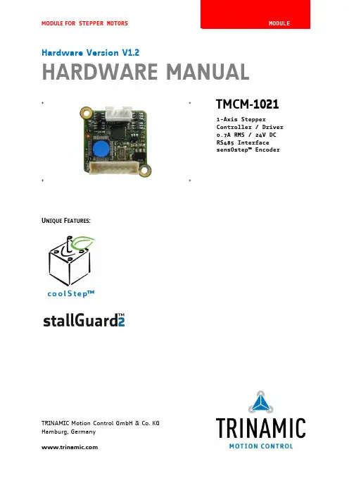
MODULE FOR STEPPER MOTORSTRINAMIC Motion Control GmbH & Co. KGHamburg, GermanyHardware Version V1.2HARDWARE MANUAL+ +TMCM-1021++U NIQUE F EATURES :Table of Contents1Features (3)2Order Codes (5)3Mechanical and Electrical Interfacing (6)3.1Size of Board (6)3.2Connectors (7)3.2.1Power, Communication and I/O Connector (8)3.2.2Motor Connector (8)3.3Power Supply (9)3.4Communication (10)3.4.1RS485 (10)3.5Inputs and Outputs (11)3.5.1Digital Inputs IN_0, IN_1, IN_2, IN_3 (11)3.5.2Outputs OUT_0, OUT_1 (12)4Reset to Factory Defaults (13)5On-board LED (13)6Operational Ratings (14)7Functional Description (15)8Life Support Policy (16)9Revision History (17)9.1Document Revision (17)9.2Hardware Revision (17)10References (17)1FeaturesThe TMCM-1021 is a single axis controller/driver module for 2-phase bipolar stepper motors with state of the art feature set. It is highly integrated, offers a convenient handling and can be used in many decentralized applications. The module can be mounted on the back of NEMA11 (28mm flange size) and has been designed for coil currents up to 0.7A RMS and 24V DC supply voltage. With its high energy efficiency from TRINAMIC’s coolStep™ technology cost for power consumption is kept down. The TMCL™ firmware allows for both, standalone operation and direct mode.M AIN C HARACTERISTICSHighlights-Motion profile calculation in real-time-On the fly alteration of motor parameters (e.g. position, velocity, acceleration)-High performance microcontroller for overall system control and serial communication protocol handling-For position movement applications, where larger motors do not fit and higher torques are not requiredBipolar stepper motor driver-Up to 256 microsteps per full step-High-efficient operation, low power dissipation-Dynamic current control-Integrated protection-stallGuard2 feature for stall detection-coolStep feature for reduced power consumption and heat dissipationEncoder-sensOstep magnetic encoder (max. 1024 increments per rotation) e.g. for step-loss detection under all operating conditions and positioning supervisionInterfaces-Up to 4 multi-purpose inputs (2 shared with outputs)- 2 general purpose outputs-RS485 2-wire communication interfaceSoftware-TMCL: s tandalone operation or remote controlled operation,program memory (non volatile) for up to 876 TMCL commands, andPC-based application development software TMCL-IDE available for free.Electrical and mechanical data-Supply voltage: +24V DC nominal (9… 28V DC)-Motor current: up to 0.7A RMS (programmable)Refer to separate TMCL Firmware Manual, too.TRINAMIC S U NIQUE F EATURES – E ASY TO U SE WITH TMCLstallGuard2™ stallGuard2 is a high-precision sensorless load measurement using the back EMF on thecoils. It can be used for stall detection as well as other uses at loads below those which stall the motor. The stallGuard2 measurement value changes linearly over a wide range of load, velocity, and current settings. At maximum motor load, the value goes to zero or near to zero. This is the most energy-efficient point of operation for the motor.Load [Nm]stallGuard2Initial stallGuard2 (SG) value: 100%Max. loadstallGuard2 (SG) value: 0Maximum load reached. Motor close to stall. Motor stallsFigure 1.1 stallGuard2 load measurement SG as a function of loadcoolStep ™coolStep is a load-adaptive automatic current scaling based on the load measurement via stallGuard2 adapting the required current to the load. Energy consumption can be reduced by as much as 75%. coolStep allows substantial energy savings, especially for motors which see varying loads or operate at a high duty cycle. Because a stepper motor application needs to work with a torque reserve of 30% to 50%, even a constant-load application allows significant energy savings because coolStep automatically enables torque reserve when required. Reducing power consumption keeps the system cooler, increases motor life, and allows reducing cost.00,10,20,30,40,50,60,70,80,9050100150200250300350EfficiencyVelocity [RPM]Efficiency with coolStepEfficiency with 50% torque reserveFigure 1.2 Energy efficiency example with coolStep2Order CodesTable 2.2 Order codesA cable loom set is available for this module:Table 2.5 Cable loom order code3Mechanical and Electrical Interfacing3.1Size of BoardThe board with the controller/driver electronics has an overall size of 28mm x 28mm in order to fit on the back side of a NEMA11 (28mm flange size) stepper motor. The printed circuit board outline is marked green in the following figure:PCB outlineR 2.5mmFigure 3.1 Board dimensions and position of mounting holes3.2ConnectorsThe TMCM-1021 has two connectors, an 8-pin power and input/output connector and a 4-pin motor connector (used to connect the attached motor).Power / Communication / IOs11MotorFigure 3.2 TMCM-1021 connectorsOverview of connector and mating connector types:Table 3.2 Connectors and mating connectors, contacts and applicable wire3.2.1Power, Communication and I/O ConnectorAn 8-pin CVIlux CI0108P1VK0-LF 2mm pitch single row connector is used for power supply, RS485 serial communication and additional multi-purpose inputs and outputs.Table 3.3 Power, communication and I/O connector3.2.2Motor ConnectorAn 4-pin CVIlux CI0104P1VK0-LF 2mm pitch single row connector is used for connecting the four motor wires to the electronics.Table 3.4 Motor connector3.3 Power SupplyFor proper operation care has to be taken with regard to power supply concept and design. Due to space restrictions the TMCM-1021 includes just about 20µF/35V of supply filter capacitors. These are ceramic capacitors which have been selected for high reliability and long life time. The module includes a 28V suppressor diode for over-voltage protection.C AUTION !Add external power supply capacitors!It is recommended to connect an electrolytic capacitor of significant size (e.g. 470µF/35V) to the power supply lines next to the TMCM-1021!Rule of thumb for size of electrolytic capacitor: In addition to power stabilization (buffer) and filtering this added capacitor will also reduce any power supply wires and the ceramic capacitors. In addition it will limit slew-rate of power supply stability problems with some switching power supplies.Do not connect or disconnect motor during operation!Motor disconnected / connected while energized. These voltage spikes might exceed voltage limits of power supply before connecting / disconnecting the motor.Keep the power supply voltage below the upper limit of 28V!Otherwise operating voltage is near the upper limit a regulated power supply is highly recommended. Please see also chapter 6, operating values.There is no reverse polarity protection!The transistors.TMCM-1021 V1.2 Hardware Manual (Rev. 1.02 / 2013-JUL-23)10 3.4Communication3.4.1RS485For remote control and communication with a host system the TMCM-1021 provides a two wire RS485 bus interface. For proper operation the following items should be taken into account when setting up an RS485 network:1.BUS STRUCTURE:The network topology should follow a bus structure as closely as possible. That is, the connection between each node and the bus itself should be as short as possible. Basically, it should be short compared to the length of the bus.termination resistor (120 Ohm)termination resistor (120 Ohm)Figure 3.5: Bus structure2.BUS TERMINATION:Especially for longer busses and/or multiple nodes connected to the bus and/or high communication speeds, the bus should be properly terminated at both ends. The TMCM-1021 does not integrate any termination resistor. Therefore, 120 Ohm termination resistors at both ends of the bus have to be added externally.3.NUMBER OF NODES:The RS485 electrical interface standard (EIA-485) allows up to 32 nodes to be connected to a single bus. The bus transceiver used on the TMCM-1021 units (SN65HVD3082ED) has just 1/8th of the standard bus load and allows a maximum of 256 units to be connected to a single RS485 bus.4.NO FLOATING BUS LINES:Avoid floating bus lines while neither the host/master nor one of the slaves along the bus line is transmitting data (all bus nodes switched to receive mode). Floating bus lines may lead to communication errors. In order to ensure valid signals on the bus it is recommended to use a resistor network connecting both bus lines to well defined logic levels. In contrast to the termination resistors this network is normally required just once per bus. Certain RS485 interface converters available for PCs already include these additional resistors (e.g. USB-2-485).terminationresistor(120 Ohm)RS485- / RS485BRS485+ / RS485AFigure 3.6 Bus lines with resistor network3.5 Inputs and Outputs3.5.1 Digital Inputs IN_0, IN_1, IN_2, IN_3The eight pin connector of the TMCM-1021 provides four general purpose inputs IN_0, IN_1, IN_2 and IN_3. The first two inputs have dedicated connector pins while the other two share pins with two general purpose outputs.All four inputs are protected using voltage resistor dividers together with limiting diodes against voltages below 0V (GND) and above +3.3V DC (see figure below).IN_0IN_1IN_2IN_3microcontroller and TMC262Figure 3.7 General purpose inputsThe four inputs have alternate functionality depending on configuration in software. The following functions are available:Table 3.5 Multipurpose inputs / alternate functionsAll four inputs are connected to the on-board processor and can be used as general purpose digital inputs.Using the alternate functionality of IN_0 and IN_1 it is possible to control the on-board stepper motor driver with the help of an external stepper motor controller using step and direction signals. For the step and direction signals the signal levels are the same as for the general purpose digital inputs.IN_3 can be used as analog input, also. A 12bit analog to digital converter integrated in the microcontroller will convert any analog input voltage between 0 and +6.6V to a digital value between 0 and 4095 then.3.5.2Outputs OUT_0, OUT_1The eight pin connector of the TMCM-1021 provides two general purpose outputs. These two outputs are open-drain outputs and can sink up to 100mA each. The outputs of the N-channel MOSFET transistors are connected to freewheeling diodes each for protection against voltage spikes especially from inductive loads (relais etc.).Both outputs OUT_0 and OUT_1 share pins with two of the four inputs (IN_2 resp. IN_3).Please take into account the 20k (2x 10k in series) resistance to ground (transistor not active) of the input voltage divider (figure 4.8) when designing the external “load” circuit.OUT_0 / IN_2OUT_1 / IN_3microcontrollerFigure 3.8 General purpose outputs4Reset to Factory DefaultsIt is possible to reset the TMCM-1021 to factory default settings without establishing a communication link. This might be helpful in case communication parameters of the preferred interface have been set to unknown values or got accidentally lost.For this procedure two pads on the bottom side of the board have to be shortened (see Figure 4.1).Please perform the following steps:1.Power supply off and USB cable disconnected2.Short two pads as marked in Figure 4.13.Power up board (power via USB is sufficient for this purpose)4.Wait until the on-board red and green LEDs start flashing fast (this might take a while)5.Power-off board (disconnect USB cable)6.Remove short between pads7.After switching on power-supply / connecting USB cable all permanent settings have been restoredto factory defaultsShort these two padsFigure 4.1 Reset to factory default settings5On-board LEDThe board offers one LED in order to indicate board status. The function of the LED is dependent on the firmware version. With standard TMCL firmware the green LED flashes slowly during operation.When there is no valid firmware programmed into the board or during firmware update the green LED is permanently on.Green LEDFigure 5.1 On-board LED6Operational RatingsThe operational ratings show the intended or the characteristic ranges and should be used as design values. In no case shall the maximum values be exceeded!Table 6.1 General operational ratings of module*) maximum setting for prototype and first versions of TMCL firmware. Will be adapted in firmware for series version.Table 6.2 Operational ratings of multi-purpose I/OsTable 6.3 Operational ratings of RS485 interface7Functional DescriptionThe TMCM-1021 is a highly integrated controller/driver module which can be controlled via RS485 interface. Communication traffic is kept low since all time critical operations (e.g. ramp calculations) are performed on board. The nominal supply voltage of the unit is 24V DC. The module is designed for both, standalone operation and direct mode. Full remote control of device with feedback is possible. The firmware of the module can be updated via the serial interface.In Figure 7.1 the main parts of the module are shown:-the microprocessor, which runs the TMCL operating system (connected to TMCL memory),-the power driver with its energy efficient coolStep feature,-the MOSFET driver stage, and-the sensOstep encoder with resolutions of 10bit (1024 steps) per revolution.9…Figure 7.1 Main parts of TMCM-1021The TMCM-1021 comes with the PC based software development environment TMCL-IDE for the Trinamic Motion Control Language (TMCL). Using predefined TMCL high level commands like move to position a rapid and fast development of motion control applications is guaranteed. Please refer to the TMCM-1021 Firmware Manual for more information about TMCL commands.8Life Support PolicyTRINAMIC Motion Control GmbH & Co. KG does not authorize or warrant any of its products for use in life support systems, without the specific written consent of TRINAMIC Motion Control GmbH & Co. KG.Life support systems are equipment intended to support or sustain life, and whose failure to perform, when properly used in accordance with instructions provided, can be reasonably expected to result in personal injury or death. © TRINAMIC Motion Control GmbH & Co. KG 2013Information given in this data sheet is believed to be accurate and reliable. However neither responsibility is assumed for the consequences of its use nor for any infringement of patents or other rights of third parties, which may result from its use.Specifications are subject to change without notice.All trademarks used are property of their respective owners.9Revision History9.1Document RevisionFigure 9.1 Document revision9.2Hardware RevisionFigure 9.2 Hardware revision10References[TMCM-1021] TMCM-1021 TMCL Firmware Manual [QSH2818-32-07-006] NEMA11 / 28mm bipolar stepper motor [QSH2818-51-07-012] NEMA11 / 28mm bipolar stepper motor [USB-2-485] USB-2-485 interface converter TRINAMIC manuals are available on .。
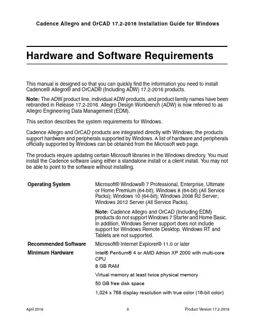
Hardware and Software RequirementsThis manual is designed so that you can quickly find the information you need to install Cadence® Allegro® and OrCAD® (Including ADW) 17.2-2016 products.Note: The ADW product line, individual ADW products, and product family names have been rebranded in Release 17.2-2016. Allegro Design Workbench (ADW) is now referred to as Allegro Engineering Data Management (EDM).This section describes the system requirements for Windows.Cadence Allegro and OrCAD products are integrated directly with Windows; the products support hardware and peripherals supported by Windows. A list of hardware and peripherals officially supported by Windows can be obtained from the Microsoft web page.The products require updating certain Microsoft libraries in the Windows directory. Y ou must install the Cadence software using either a standalone install or a client install. Y ou may not be able to point to the software without installing.Operating System Microsoft® Windows® 7 Professional, Enterprise, Ultimateor Home Premium (64-bit); Windows 8 (64-bit) (All ServicePacks); Windows 10 (64-bit); Windows 2008 R2 Server;Windows 2012 Server (All Service Packs).Note: Cadence Allegro and OrCAD (Including EDM)products do not support Windows 7 Starter and Home Basic.In addition, Windows Server support does not includesupport for Windows Remote Desktop. Windows RT andT ablets are not supported.Recommended Software Microsoft® Internet Explorer® 11.0 or laterMinimum Hardware Intel® Pentium® 4 or AMD Athlon XP 2000 with multi-coreCPU8 GB RAMVirtual memory at least twice physical memory50 GB free disk space1,024 x 768 display resolution with true color (16-bit color)Broadband Internet connection for some serviceEthernet card (for network communications and securityhostID)Three-button Microsoft-compatible mouseRecommended Hardware Intel® Core™ 2 Duo 2.66 GHz or AMD Athlon 64 X2 5200+Note: Faster processors are preferred.8 GB RAM500 GB free disk space1,280 x 1024 display resolution with true color (at least 32bitcolor)A dedicated graphics cardFor physical design dual monitorsBroadband Internet connection for some services Network Interface Cards (NICs)A network interface card (NIC) is the preferred locking method used in licensing to enable the products to run on a computer. Each NIC is programmed with an address that is sufficiently unique to enable its use as a hardware lock.Y ou can use the NIC in a laptop computer as your locking method, but you should be aware that in some laptops NICs are disabled if the laptops are not attached to a network. If your laptop’s NIC is disabled, you will not be able to run any products.DonglesIf your locking method is a dongle, attach the dongle to the appropriate parallel or USB port of the computer before you begin the installation. Click Cancel when the Windows generated Found New Hardware dialog appears. The dongle drivers will automatically install during the License Manager Installation.The following dongle is supported for Release 17.2-2016:■FLEXid USB dongle (version 9, flexid9)Cadence License FileIn order to run the Cadence Allegro and OrCAD products, you must have a valid license file (LICENSE.TXT) issued by Cadence.。
failure in the radio interfaceprocedure 原因Failure in the Radio Interface Procedure: Causes and SolutionsA failure in the radio interface procedure can occur for various reasons, causing disruption in communication between mobile devices and the network. This article aims to explore the possible causes behind this issue and provide potential solutions to address them effectively.1. Network Congestion:One of the common reasons for a failure in the radio interface procedure is network congestion. When the network experiences high traffic or overloaded conditions, it can lead to interference and result in communication failure. This congestion can occur due to a surge in the number of users, inadequate network capacity, or insufficient resource allocation. To mitigate this issue, network operators need to invest in expanding network infrastructure and prioritize resources based on demand.2. Signal Interference:Signal interference can also be a factor contributing to a failure in the radio interface procedure. This interference can occur due to environmental factors such as physical obstacles, weather conditions, or electromagnetic interference from other devices. To minimize signal interference, operators should conduct regular site surveys to identify potential sources and take necessary measures to mitigate their impact, such as optimizing antenna placements or implementing shielding mechanisms.3. Hardware or Software Glitches:Faulty hardware or software within the mobile device or network equipment can lead to failures in the radio interface procedure. This may include malfunctioning antennas, out-of-date firmware, or incompatible software configurations. Regular maintenance andsoftware updates are crucial to keep the network infrastructure and mobile devices in optimal condition. Additionally, thorough testing before deploying any updates or new equipment can help identify and rectify potential glitches.4. Coverage Issues:Insufficient network coverage in certain areas can result in a failure in the radio interface procedure. This may include dead zones or areas with weak signal strength. Network operators need to conduct accurate coverage analysis and, if required, deploy additional base stations or repeaters to enhance signal coverage. Additionally, implementing technologies like beamforming or using higher frequency bands can help improve coverage in challenging areas.5. Authentication or Encryption Errors:Issues with authentication or encryption protocols can lead to a failure in the radio interface procedure. These errors are typically associated with incorrect configuration or compatibility issues between the mobile device and the network. Ensuring that devices and network equipment adhere to standardized protocols and regularly updating security measures can help minimize authentication or encryption errors.In conclusion, a failure in the radio interface procedure can arise from network congestion, signal interference, hardware or software glitches, coverage issues, or authentication/encryption errors. By investing in network expansion, conducting regular maintenance, optimizing signal coverage, and ensuring adherence to standardized protocols, network operators can mitigate these issues and provide a smoother and more reliable communication experience for users.。
Application Note AC427July 20141© 2014 Microsemi Corporation Loading and Debugging Core8051s Application From External Flash MemoryTable of ContentsPurposeThis application note describes how to load and debug application code from external flash memory available on the Microsemi ® Cortex-M1-enabled ProASIC3L Development Kit.IntroductionA Core8051s based microcontroller system is implemented on the Microsemi M1 enabled ProASIC3L field programmable gate array (FPGA). The external flash memory is interfaced to the Core8051s microcontroller system to load and debug the application code.ReferencesThe following references are used in this document:•Core8051s Based Hardware Tutorial •Core8051s Based Software User GuidePurpose . . . . . . . . . . . . . . . . . . . . . . . . . . . . . . . . . . . . . . . . . . . . . . . . . . 1Introduction . . . . . . . . . . . . . . . . . . . . . . . . . . . . . . . . . . . . . . . . . . . . . . . . 1References . . . . . . . . . . . . . . . . . . . . . . . . . . . . . . . . . . . . . . . . . . . . . . . . 1Design Requirements . . . . . . . . . . . . . . . . . . . . . . . . . . . . . . . . . . . . . . . . . . 2Design Overview . . . . . . . . . . . . . . . . . . . . . . . . . . . . . . . . . . . . . . . . . . . . . 2Design Description . . . . . . . . . . . . . . . . . . . . . . . . . . . . . . . . . . . . . . . . . . . . 3Running the Design Example . . . . . . . . . . . . . . . . . . . . . . . . . . . . . . . . . . . . . . 13Conclusion . . . . . . . . . . . . . . . . . . . . . . . . . . . . . . . . . . . . . . . . . . . . . . . 22Appendix A – Design and Programming Files . . . . . . . . . . . . . . . . . . . . . . . . . . . . . 22List of Changes . . . . . . . . . . . . . . . . . . . . . . . . . . . . . . . . . . . . . . . . . . . . . 23Loading and Debugging Core8051s Application From External Flash Memory2Design RequirementsDesign OverviewA Core8051s IP based microcontroller system is developed with peripheral IPs such as CoreGPIO,CoreUARTapb, CoreWatchdog, CoreTimer, and CoreAPB3 that are implemented on the Microsemi Cortex-M1-enabled ProASIC3L Development Kit . An external Micron JS28F640J3D-75 flash memory is interfaced to the Core8051s microcontroller system. A simple application is loaded into the external Micron JS28F640J3D-75 flash memory to blink the on-board LEDs. Figure 1 shows the Core8051s microcontroller system.Table 1 • Design RequirementsDesign RequirementsDescriptionHardware RequirementsCortex-M1-enabled ProASIC3L Development Kit-Host PC or LaptopAny 64-bit Windows Operating System Software RequirementsLibero ® System-on-Chip (SoC)v11.3SoftConsolev3.4One of the following serial terminal emulation programs:• HyperTerminal• TeraTerm• PuTTY -Figure 1 • Core8051s Microcontroller SystemDesign Description3Design DescriptionThis design example has the following IPs that are available in Libero SoC catalog:•Core8051s : an 8-bit microcontroller IP core •CoreGPIO : provides up to 32-bit inputs and 32-bit outputs for general purpose •CoreUARTapb : a serial communication interface •CoreWatchdog : provides a means of recovering from software crashes •CoreTimer : for interrupt-generation and programmable counter •CoreAPB3: a bus component that provides advanced microcontroller bus architecture (AMBA3)advanced peripheral bus (APB3) fabric supporting up to 16 APB slavesThe following sections provide a brief description of each IP and its configuration:•Core8051s Description•Difference Between Core8051s and Core8051•CoreAPB3 Description•External Flash Memory Description•CoreTimer Description•CoreWatchdog Description•CoreUARTapb Description•CoreGPIO Description•Description of Core8051s based Microcontroller System•Memory Map•Software Development Description Core8051s DescriptionThe Core8051s is a high-performance, 8-bit microcontroller IP core. It is an 8-bit embedded controller that executes all ASM51 instructions and has the same instruction set as 80C31. It provides software and hardware interrupts. It eliminates redundant bus states and implements parallel execution of fetch and execution phases. The Core8051s uses one clock per cycle, and most of the one byte instructions are performed in a single clock cycle. Figure 2 shows the Core8051s architecture.Difference Between Core8051s and Core8051The Core8051s is smaller and more flexible than the Core8051.The microcontroller-specific features such as SFR-mapped peripherals, power management circuitry, serial channel, I/O ports and timers of the original 8051 are not present in Core8051s. The Core8051s contains the main 8051 core logic, but it does not have peripheral logic. The Core8051s has an advanced peripheral bus interface that can be used like the SFR (special function register) bus to easily expand the functionality of the core by connecting it to the existing advanced peripheral bus IPs. The Core8051s allows to configure the coreFigure 2 • Core8051s ArchitectureLoading and Debugging Core8051s Application From External Flash Memory4with the peripheral functions (timers, UARTs, I/O ports, etc.) that are required for the application.Configure the Core8051s Configurator GUI as shown in Figure 3.Refer to the Core8051s Handbook for more details.CoreAPB3 DescriptionThe CoreAPB3 is a bus component that provides advanced microcontroller bus architecture (AMBA3)advanced peripheral bus (APB3) fabric supporting up to 16 APB slaves, and a single APB master. The CoreAPB3 can be used with an APB3 master that does not have a built-in APB address decoding, such as Core8051s. A single APB3 master is connected to CoreAPB3. The master’s PSEL and PADDR signals are used within the CoreAPB3 to decode the appropriate PSELS slave select signals, and only one signal can be active at a time. This address decoding depends on the RANGESIZE hardware parameter/generic. Refer to the CoreAPB3 Handbook for more information.Figure 3 • Core8051s Configurator GUIDesign Description5Configure the CoreAPB3 Configurator GUI as shown in Figure 4.External Flash Memory DescriptionPart Number:•Micron JS28F640J3D-75Architecture: •64 Mbit (64 blocks)Performance: •75 ns Initial Access Speed, 25 ns 8-word and 4-word Asynchronous page-mode reads •32-Byte Write buffer (4 μs per Byte Effective programming time)System voltage: •VCC = 2.7 V to 3.6 V and VCCQ = 2.7 V to 3.6 V Enhanced security options for code protection:•128-bit Protection Register (64-bits unique device identifier bits, 64-bits user-programmable OTP (one time programmable) bits)•Absolute protection with VPEN = GND •Individual block locking •Block erase/program lockout during power transitions Figure 4 • CoreAPB3 Configurator GUILoading and Debugging Core8051s Application From External Flash Memory6Software:•Program and erase suspend support•Flash data integrator (FDI)•Common flash interface (CFI) compatibleThe external flash memory device can be accessed as 8- or 16-bit words. A command user interface (CUI) serves as the interface between the system processor and the internal operation of the device. A valid command sequence written to the CUI that initiates the device automation. An internal write state machine (WSM) automatically executes the algorithms and timings necessary for block erase, program, and lock-bit configuration operations.Flash operations are command-based, where command codes are first issued to the flash memory, then the flash memory performs the required operation. Refer to the flash memory Micron JS28F640J3D-75 datasheet for a list of command codes and flowcharts. Flash memory has a read-only 8-bit status register that indicates the flash memory status and operational errors. Four types of data can be read from the flash memory: array data, device information, CFI data, and device status.The flash memory is set to Read Array mode by default after power-up or reset. Executing the Read Array command sets the flash memory to Read Array mode and reads the output array data. The flash memory remains in Read Array mode until a different read command is executed. To change the flash memory to Read Array mode while it is programming or erasing, first issue the suspend command. After suspending the operation, run the Read Array command to set to Read Array mode. When the program or erase operation is subsequently resumed, the flash memory automatically sets to Read Status mode. Issuing the Read Device Information command places the flash memory in Read Device Information mode and reads the output of the device information. The flash memory remains in Read Device Information mode until a different read command is issued. Also, performing a program, erase, or block-lock operation changes the flash memory to Read Status Register mode.Array programming is performed by first issuing the single-word/byte program command. This is followed by writing the desired data at the desired array address. The read mode of the device is automatically changed to Read Status Register mode, which remains in effect until another read-mode command is issued.Erasing a block changes zeros to ones. To change ones to zeros, a program operation must be performed. Erasing is performed on a block basis - an entire block is erased each time when an erase command sequence is issued. Once a block is fully erased, all addressable locations within that block read as logical ones (FFFFh). Only one block-erase operation can occur at a time, and it is not allowed during a program suspend. To perform a block-erase operation, issue the block erase command sequence at the required block address. An erase or programming operation can be suspended to perform other operations, and then subsequently resumed. To suspend an on-going erase or a program operation, issue the suspend command to any address.All blocks are unlocked at the factory. Blocks can be locked individually by issuing the set block lock bit command sequence to any address within a block. Once locked, blocks remain locked when power cable is unplugged or when the device is reset. All locked blocks are unlocked simultaneously by issuing the clear block lock bits command sequence to any device address. The locked blocks cannot be erased or programmed.The sequence of the commands that must be given to the flash memory are written in an XML file. The XML files are provided with the SoftConsole software for the JS28F640J3D-75 flash memory located at: C:\Program Files (x86)\Microsemi\SoftConsole v3.4\Sourcery-G++\share\sprite\flash.Design Description7CoreTimer DescriptionThe CoreTimer is an APB slave that provides a functionality for the interrupt generations, and a programmable decrementing counter. It is configurable and programmable, and can be used in either continuous or one-shot modes. It is an essential element in many designs because it supports accurate generation of timing for precise application control. Refer to the CoreTimer Handbook for more information. Configure the CoreTimer Configurator GUI as shown in Figure 5.CoreWatchdog DescriptionThe CoreWatchdog is an APB slave that provides a means of recovering from software crashes. When the CoreWatchdog is enabled, the core generates a soft reset if the microprocessor fails to refresh it on a regular basis. The CoreWatchdog can be configured based on a decrementing counter, which asserts a reset signal if it is allowed to time out. The width of the decrementing counter can be configured as either 16 or 32-bits. The processor-accessible registers in CoreWatchdog provide a means to control and monitor the operation of the core. Refer to the CoreWatchdog Handbook for more information.Configure the CoreWatchdog Configurator GUI as shown in Figure 6.Figure 5 • CoreTimer Configurator GUIFigure 6 • CoreWatchdog Configurator GUILoading and Debugging Core8051s Application From External Flash Memory8CoreUARTapb DescriptionThe CoreUARTapb is a serial communications interface that is primarily used in the embedded systems.The controller can operate in either an asynchronous (UART) or a synchronous mode. In asynchronous mode, the CoreUARTapb can be used to interface directly to industry standard UARTs. The CoreUARTapb has an APB-wrapper that adds an APB interface allowing the core to be connected to the APB bus and controlled by an APB bus master. Unlike a standard 8051 UART, the CoreUARTapb includes a baud rate generator and so does not need a separate timer for the baud rate. Refer to the CoreUARTapb Handbook for more information.Configure the CoreUARTapb Configurator GUI as shown in Figure 7.Figure 7 • CoreUARTapb Configurator GUIDesign Description9CoreGPIO DescriptionThe CoreGPIO is an APB bus peripheral that provides up to 32-bit inputs and 32-bit outputs for general purpose. Refer to the CoreGPIO Handbook for more information.Configure the CoreGPIO Configurator GUI as shown in Figure 8.Figure 8 • CoreGPIO Configurator GUILoading and Debugging Core8051s Application From External Flash Memory10Description of Core8051s based Microcontroller System All the peripherals are interfaced to the Core8051s as shown in Figure 9.Refer to the Core8051s Based Hardware Tutorial for more information.Figure 9 • SmartDesign Top-Level Block DiagramDesign Description Instantiate a two port RAM on the SmartDesign top-level and configure it as shown in Figure10.Figure 10 • SRAM ConfigurationExternal memory buffer and multiplexer are configured as shown in Figure11 and Figure12.Figure 11 • External Memory Buffer ConfigurationLoading and Debugging Core8051s Application From External Flash MemoryMemory MapRight-click the Modify Memory Map to see the memory map as shown in Figure 13.Software Development DescriptionThe drivers are generated from firmware catalog for CoreTimer, CoreGPIO, CoreWatchdog, CoreTimer,and hardware abstraction layer (HAL). The HAL is used by drivers to access the hardware and also allows the control of interrupts.Refer to the Core8051s Based Software User Guide for more information.The Core8051s hardware design provides access to the external flash memory and internal SRAM. The Core8051s flash programming flow for Core8051s program memory is similar to the existing programming flow for Cortex-M1 flash program memory. The principal difference is, instead of specifying the location, size and the type of the program memory in a linker script, the program memory details are given in a text file (a memory-region-file) which uses the same syntax as the memory command section of a GCC linker script. The SoftConsole project configuration must be modified to specify the memory-region-file as an argument to the actel-map.exe helper program. Application code is written in main.c of the SoftConsole project to blink the on-board LED's.Figure 12 • Multiplexer ConfigurationFigure 13 • Memory MapRunning the Design ExampleRunning the Design ExampleTo run the design example,1.Download the design example at,/download/rsc/?f=Core8051s_ExtFlashIntSRAM_DF2.Double-click the Program Device under Program Design to program the Cortex-M1-enabledProASIC3L Development Kit in the Design Flow window, as shown in Figure14.Figure 14 • Program DeviceLoading and Debugging Core8051s Application From External Flash Memory3.Open the SoftConsole project after successfully programming the device, as shown in Figure15.Figure 15 • SoftConsole Project WindowRunning the Design Example4.Right-click the Core8051s_ExtFlashIntSRAM on the left pane and click Properties, as shown inFigure16. The Properties window is displayed as shown in Figure16.Figure 16 • Project Properties5.Double-click Settings under C/C++ Build on the left pane of Properties window.Loading and Debugging Core8051s Application From External Flash Memory6.Click Tools Settings tab on the right pane and select the Memory map generator, as shown inFigure 17.7.Enter actel-map -M../intel-28f640-1x8-code-memory.txt text in the Command field.Note:The “intel-28f640-1x8” XML file, which is at C:\Program Files (x86)\Microsemi\SoftConsolev3.4\Sourcery-G++\share\sprite\flash is used for loading and debugging the JS28F640J3D-75 flash memory.Figure 17 • Memory Map GeneratorRunning the Design Example8.Right-click Core8051s_ExtFlashIntSRAM on the left pane and click Debug As > DebugConfigurations…, as shown in Figure18. The Debug Configurations window is displayed.Figure 18 • Debug ConfigurationsLoading and Debugging Core8051s Application From External Flash Memory9.Right-click Microsemi Core8051s Target and click New to create a new debug configuration, asshown in Figure19.Figure 19 • New Debug Configuration10.Click Debug.Figure 20 • Debug ConfigurationsRunning the Design Example After launching the debug session, the flash programming operation starts. The erase and writeoperations are shown in Figure21.Figure 21 • Flash ProgrammingLoading and Debugging Core8051s Application From External Flash Memory11.Start PuTTY (with settings 57600 baud rate, 8 data bits, and No parity), and choose Resumefrom the Run menu. The LEDs are scanned on the Cortex-M1-enabled ProASIC3L Development Kit in the forward and reverse direction. The messages are displayed as shown in Figure 22.12.Terminate and relaunch the debug session.13.Set break points at 60, 115 and 149 lines of main.c.14.Choose Resume from the Run menu.15.Choose Step Over from the Run menu until it reaches the 115 line of main.c. The “RunningCore8051s Application from External Flash Memory” message is displayed as shown in Figure 23.Figure 22 • Application Running From External Flash MemoryFigure 23 • Debug CodeRunning the Design Example2116.Choose Step Over from the Run menu. While stepping over the code, the LEDs blinks on theMicrosemi Cortex-M1-enabled ProASIC3L Development Kit . The message is displayed as shown in Figure 24.Figure 24 • Step OverLoading and Debugging Core8051s Application From External Flash Memory2217.Right-click Core8051s_ExtFlashIntSRAM Debug [Microsemi Core8051 Target] and clickTerminate and Remove the debug session as shown in Figure 25.18.Choose Exit from the File menu to close the SoftConsole project.19.Unplug the USB cables and power supply cable and plug-in the power supply cable. The sameLED scanning application runs from the non-volatile external flash memory.ConclusionThis application note describes how to load and debug the Core8051s application from the external flash memory using SoftConsole. The example design serves as a starting point to other Core8051s designs.It includes a Core8051s based system, firmware drivers, and a sample LED scanning application that runs from the external flash memory.Appendix A – Design and Programming FilesYou can download the design files from the Microsemi SoC Products Group website:/download/rsc/?f=Core8051s_ExtFlashIntSRAM_DFThe design file consists of Libero project and programming file. Refer to the Readme.txt file included in the design file for directory structure and description.Figure 25 • Terminate and Remove Debug SessionList of Changes 23List of ChangesThe following table lists the critical changes that were made in the current version of the application note.DateChanges Page Revision 1(July 2014)Initial Release.NA51900295-1/7.14© 2014 Microsemi Corporation. All rights reserved. Microsemi and the Microsemi logo are trademarks of Microsemi Corporation. All other trademarks and service marks are the property of their respective owners.Microsemi Corporate HeadquartersOne Enterprise, Aliso Viejo CA 92656 USA Within the USA: +1 (800) 713-4113 Outside the USA: +1 (949) 380-6100Sales: +1 (949) 380-6136Fax: +1 (949) 215-4996E-mail:***************************Microsemi Corporation (Nasdaq: MSCC) offers a comprehensive portfolio of semiconductor and system solutions for communications, defense and security, aerospace, and industrial markets. Products include high-performance and radiation-hardened analog mixed-signal integrated circuits, FPGAs, SoCs, and ASICs; power management products; timing and synchronization devices and precise time solutions, setting the world's standard for time; voice processing devices; RF solutions; discrete components; security technologies and scalable anti-tamper products; Power-over-Ethernet ICs and midspans; as well as custom design capabilities and services. Microsemi is headquartered in Aliso Viejo, Calif. and has approximately 3,400 employees globally. Learn more at .。
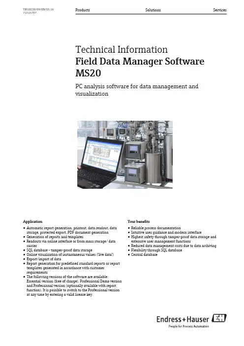
Application•Automatic report generation, printout, data readout, data storage, protected export, PDF document generation •Generation of reports and templates•Readouts via online interface or from mass storage/ data carrier•SQL database - tamper-proof data storage•Online visualization of instantaneous values ("live data")•Export/import of data•Report generation for predefined standard reports or report templates generated in accordance with customer requirements•The following versions of the software are available: Essential version (free of charge), Professional Demo version and Professional version (optionally available with report function). It is possible to switch to the Professional version at any time by entering a valid license key.Your benefits•Reliable process documentation•Intuitive user guidance and modern interface •Highest safety through tamper-proof data storage and extensive user management functions•Reduced data management costs due to data archiving •Flexibility through SQL database•Central databaseProducts Solutions ServicesTechnical InformationField Data Manager SoftwareMS20PC analysis software for data management andvisualizationTI01022R/09/EN/05.1671315797Field Data Manager Software MS202Endress+HauserGeneral informationField Data Manager (FDM) is a software package that offers centralized data management with visualization for recorded data.This enables all measuring point data to be completely archived, e.g.:•Measured values •Diagnostic events •Analyses •Event logbookThe following versions of the software are available:•Essential version: This software version is available free of charge with restricted functionality.•Professional Demo version: The demo version has the full range of functionality but is valid for 90days only. After 90 days it is downgraded to the Essential version. The reporting option is not included in the demo version.•Professional version: This version has the full range of functionality and can be purchased using a licensing model.•Professional version with reporting: In addition to the functionality of the Professional version, it is possible to generate reports (based on the templates provided or in accordance with customer requirements).It is possible to switch from the Essential version and the Demo version to the Professional version at any time by entering a valid license key.FDM saves the data in an SQL database. The database can be operated locally or in a network (client / server). The following databases are supported:•PostgreSQL™ (for Essential, Demo and Professional version): You an install and use the free PostgreSQL database provided on the FDM DVD.•Oracle™ (for Demo and Professional version): version 8i or higher. To set up user login, please contact your database administrator.•Microsoft SQL Server™ (for Demo and Professional version): version 2005 or higher. To set up user login, please contact your database administrator.Versions The following table shows the range of functionality of the different software versions:Field Data Manager Software MS20Endress+Hauser 3System requirements In order to install and operate the FMD software, the following hardware and software requirements must be met:Hardware requirements for FDM software:•PC with Pentium TM 4 (≥2 GHz)•PC with Pentium TM M (≥1 GHz)•PC with AMD TM (≥1.6 GHz)•Minimum 512 MB RAM cache •Minimum 1 GB free hard disk memory •Minimum screen resolution of 1024 x 800 pixel •CD/DVD driveHardware requirements for reporting server:•The installation of the reporting server (BPI dashboard) requires approx. 1 GB of hard disk memory. If additional report projects are uploaded, these files are also factored in, in which case they usually require only a few MB of hard disk memory.•The dashboard's Tomcat service requires approx. 1.5 GB of working memory. If the server is used only for reporting, 4 GB of working memory are sufficient. If it is used to run other applications,the memory requirement must be factored in.Field Data Manager Software MS204Endress+HauserOperating system/software for FDM software:•Microsoft TM Windows TM 2000 SP4•Microsoft TM Windows TM Server 2003 R2 SP2 Standard, Enterprise (32 Bit)•Microsoft TM Windows TM Server 2008 (32/64 Bit)•Microsoft TM Windows TM Server 2012 (64 Bit)•Microsoft TM XP SP2 (32 Bit)•Microsoft TM Vista TM (32/64 Bit)•Windows 7TM (32/64 Bit)•Windows 8TM (32/64 Bit)•Windows 10TM (32/64 Bit)•Windows TM .NET 2.0 SP1Operating system for reporting server:•Windows 7TM (64 Bit)•Microsoft TM Windows TM Server 2008 (64 Bit)•Microsoft TM Windows TM Server 2012 R2 (64 Bit)Ordering informationLicensing model The basic installation of the Professional version of the FDM software includes an interface to the SQL database and a Postgre™ SQL database as well as all main functions. In the Professional version with reporting option, report generation is also possible. If another supported SQL database (e.g. an already existing installation) is to be used, FDM can also be connected to the existing database. If the Professional version of the FDM software is to be installed on several workstations, one license is required per workstation .Ordering information Detailed ordering information is available from the following sources:•In the Product Configurator on the Endress+Hauser website: -> Click "Corporate"-> Select your country -> Click "Products" -> Select the product using the filters and search field ->Open product page -> The "Configure" button to the right of the product image opens the Product Configurator.•From your Endress+Hauser Sales Center:Product Configurator - the tool for individual product configuration •Up-to-the-minute configuration data •Depending on the device: Direct input of measuring point-specific information such as measuring range or operating language •Automatic verification of exclusion criteria •Automatic creation of the order code and its breakdown in PDF or Excel output format •Ability to order directly in the Endress+Hauser Online ShopOrder code Order code for Endress+Hauser Field Data Manager software:MS20-A1 (Professional version; 1x workstation license)MS20-A1+E1 (Professional version with reporting option; 1x workstation license)Demo version The Demo version can be used free of charge and without obligation for 90 days. The reporting option is not included in the Demo version. The current version of the Field Data Manager software can be found at: /ms20Updates Updates to the current version of the software are included in the purchase of the Professional version. The updates can be downloaded free of charge from /ms20. New versions of report projects are also made available here.Scope of deliveryA DVD with serial number and license key is dispatched with each license ordered. The license key is required when the software is installed for the first time.Field Data Manager Software MS20Endress+Hauser 5Supplementary documentation•System Components and Data Managers brochure (FA00016K/09)•Operating Instructions FDM "Field Data Manager Software" Online Help and Manual (BA00288R/09)•Brief Operating Instructions "Field Data Manager Software" (KA00466C/07)•Field Data Manager (FDM) – Energy Consumption Reports (CP01186R/11/EN)。
硬件 hardware 软件 software 网络 network一、硬件(hardware)主板 mainboard 或者 motherboard 显卡 graphics card 或者 display card磁盘 disk 硬盘 harddisk 软盘 softdisk 驱动器 drive光驱 cd/dvd-rom drive 刻录光驱cd-raw drive 电源 power 网卡 network interface card 简称 NIC 声卡 sound card 中央处理器 CPU center process unit 主机 host 鼠标 mouse 键盘 keyboard 显示器 displayer 或者 monitor设备 device 内存 memory 端口 port 中断 int 接口 interface 并行端口 LPT 串行端口 com 芯片 chip 计算机 computer 个人计算机或者电脑 pc打印机 printer 扫描仪 scanner 摄像头 cameras二、软件(software)程序 program 文件 file 文件夹 folder 系统 system 应用 application文档 document 设置 set 安装 setup 或者 install 卸载 uninstall退出 exit 或 quit 管理员 administrator 用户 user 加载或载入 load发送 send 共享 share 选择 select 驱动程序 driver 备份 backup复制 copy 粘贴 paste 剪切 cut 删除 delete 插入 insert 保存 save另存为 save as 编辑 edit 打印 print 查找 search 移动 move属性 property 打开 open 关闭 close 安全 security 工具 tool安全模式 safemodel 启动 boot 页面 page 病毒 virus 杀毒 kill virus查询 query 表单 table 追加 append 媒介 media 音量 volume重启 restart 或reboot 锁定 lock 格式化 format 分区 partition主引导记录 mbr 镜像 mirror 磁盘阵列 disk array 组 group 服务 sevice 桌面 desktop 运行 run 字体 font 屏幕 screen 地址 address 缓存 cacheram 读写存储器 rom 只读存储器 video 视频数据 data 检测 test 或 detect 访问 access 激活 active 配置 config 菜单 menu 标题 title 状态 status 三、网络 (network)调制解调器(俗称“猫”) modem 交换机 switcher 集线器 hub路由器 router 网卡 NIC局域网 local area network 简称 LAN城域网 metropolitan area network 简称 MAN广域网 WANWide Area Network 简称 WAN互联网 internet服务器 server 客户端 client 远程登陆 telnet 协议 potocol文件传输协议 file transfer protocol 简称 FTP超文件传输协议 hyper text transfer potocol 简称 HTTP简单传输协议 simple message transfer potocol 简称 SMTP传输控制协议 transmission control potocol 简称 TCP用户数据包协议 user datagram protocol简称 UDP动态域名服务器 dynamic domain server 简称 DNS动态主机配置服务器 dynamic host configuration potocol server 简称 DHCP无线 wireless 非屏弊双绞线 UTP 下载 download 上传 upload 连接connection通讯 communication 本地 local 远程 remote 网关 gateway 域名 domain 子网掩码 subnet mask 数据包 package 线路 line主板zhong3GIO(Third Generation Input/Output,第三代输入输出技术)ACR(Advanced Communications Riser,高级通讯升级卡)ADIMM(advanced Dual In-line Memory Modules,高级双重内嵌式内存模块)AGTL+(Assisted Gunning Transceiver Logic,援助发射接收逻辑电路)AHCI(Advanced Host Controller Interface,高级主机控制器接口)AIMM(AGP Inline Memory Module,AGP板上内存升级模块)AMR(Audio/Modem Riser;音效/调制解调器主机板附加直立插卡)AHA(Accelerated Hub Architecture,加速中心架构)AOI(Automatic Optical Inspection,自动光学检验)APU(Audio Processing Unit,音频处理单元)ARF(Asynchronous Receive FIFO,异步接收先入先出)ASF(Alert Standards Forum,警告标准讨论)ASK IR(Amplitude Shift Keyed Infra-Red,长波形可移动输入红外线)AT(Advanced Technology,先进技术)ATX(AT Extend,扩展型AT)BIOS(Basic Input/Output System,基本输入/输出系统)CNR(Communication and Networking Riser,通讯和网络升级卡)CSA(Communication Streaming Architecture,通讯流架构)CSE(Configuration Space Enable,可分配空间)COAST(Cache-on-a-stick,条状缓存)DASP(Dynamic Adaptive Speculative Pre-Processor,动态适应预测预处理器)DB: Device Bay,设备插架DMI(Desktop Management Interface,桌面管理接口)DOT(Dynamic Overclocking Technonlogy,动态超频技术)DPP(direct print Protocol,直接打印协议DRCG(Direct Rambus clock generator,直接RAMBUS时钟发生器)DVMT(Dynamic Video Memory Technology,动态视频内存技术)E(Economy,经济,或Entry-level,入门级)EB(Expansion Bus,扩展总线)EFI(Extensible Firmware Interface,扩展固件接口)EHCI(Enhanced Host Controller Interface,加强型主机端控制接口)EISA(Enhanced Industry Standard Architecture,增强形工业标准架构)EMI(Electromagnetic Interference,电磁干扰)ESCD(Extended System Configuration Data,可扩展系统配置数据)ESR(Equivalent Series Resistance,等价系列电阻)FBC(Frame Buffer Cache,帧缓冲缓存)FireWire(火线,即IEEE1394标准)FlexATX(Flexibility ATX,可扩展性ATX)FSB(Front Side Bus,前端总线)FWH(Firmware Hub,固件中心)GB(Garibaldi架构,Garibaldi基于ATX架构,但是也能够使用WTX构架的机箱)GMCH(Graphics & Memory Controller Hub,图形和内存控制中心)GPA(Graphics Performance Accelerator,图形性能加速卡)GPIs(General Purpose Inputs,普通操作输入)GTL+(Gunning Transceiver Logic,发射接收逻辑电路)HDIT(High Bandwidth Differential Interconnect Technology,高带宽微分互连技术)HSLB(High Speed Link Bus,高速链路总线)HT(HyperTransport,超级传输)I2C(Inter-IC)I2C(Inter-Integrated Circuit,内置集成电路)IA(Instantly Available,即时可用)IBASES(Intel Baseline AGP System Evaluation Suite,英特尔基线AGP系统评估套件)IC(integrate circuit,集成电路)ICH(Input/Output Controller Hub,输入/输出控制中心)ICH-S(ICH-Hance Rapids,ICH高速型)ICP(Integrated Communications Processor,整合型通讯处理器)IHA(Intel Hub Architecture,英特尔Hub架构)IMB(Inter Module Bus,隐藏模块总线)INTIN(Interrupt Inputs,中断输入)IPMAT(Intel Power Management Analysis Tool,英特尔能源管理分析工具)IR(infrared ray,红外线)IrDA(infrared ray,红外线通信接口,可进行局域网存取和文件共享)ISA(Industry Standard Architecture,工业标准架构)ISA(instruction set architecture,工业设置架构)K8HTB(K8 HyperTransport Bridge,K8闪电传输桥)LSI(Large Scale Integration,大规模集成电路)LPC(Low Pin Count,少针脚型接口)MAC(Media Access Controller,媒体存储控制器)MBA(manage boot agent,管理启动代理)MC(Memory Controller,内存控制器)MCA(Micro Channel Architecture,微通道架构)MCH(Memory Controller Hub,内存控制中心)MDC(Mobile Daughter Card,移动式子卡)MII(Media Independent Interface,媒体独立接口)MIO(Media I/O,媒体输入/输出单元)MOSFET(metallic oxide semiconductor field effecttransistor,金属氧化物半导体场效应晶体管)MRH-R(Memory Repeater Hub,内存数据处理中心)MRH-S(SDRAM Repeater Hub,SDRAM数据处理中心)MRIMM(Media-RIMM,媒体RIMM扩展槽)MSI(Message Signaled Interrupt,信息信号中断)MSPCE(Multiple Streams with Pipelining and Concurrent Execution,多重数据流的流水线式传输与并发执行)MT=MegaTransfers(兆传输率)MTH(Memory Transfer Hub,内存转换中心)MuTIOL(Multi-Threaded I/O link,多线程I/O链路)NCQ(Native Command Qu,本地命令序列)NGIO(Next Generation Input/Output,新一代输入/输出标准)NPPA(nForce Platform Processor Architecture,nForce平台处理架构)OHCI(Open Host Controller Interface,开放式主控制器接口)ORB(operation request block,操作请求块)ORS(Over Reflow Soldering,再流回焊接,SMT元件的焊接方式)P64H(64-bit PCI Controller Hub,64位PCI控制中心)PCB(printed circuit board,印刷电路板)PCBA(Printed Circuit Board Assembly,印刷电路板装配)PCI(Peripheral Component Interconnect,互连外围设备)PCI=E(PCI-Express)PCI SIG(Peripheral Component Interconnect Special Interest Group,互连外围设备专业组)PDD(Performance Driven Design,性能驱动设计)PHY(Port Physical Layer,端口物理层)POST(Power On Self Test,加电自测试)PS/2(Personal System 2,第二代个人系统)PTH(Plated-Through-Hole technology,镀通孔技术)RE(Read Enable,可读取)QP(Quad-Pumped,四倍泵)RBB(Rapid BIOS Boot,快速BIOS启动)RNG(Random number Generator,随机数字发生器)RTC(Real Time Clock,实时时钟)KBC(KeyBroad Control,键盘控制器)SAP(Sideband Address Port,边带寻址端口)SBA(Side Band Addressing,边带寻址)SBC(single board computer,单板计算机)SBP-2(serial bus protocol 2,第二代串行总线协协)SCI(Serial Communications Interface,串行通讯接口)SCK (CMOS clock,CMOS时钟)SDU(segment data unit,分段数据单元)SFF(Small Form Factor,小尺寸架构)SFS(Stepless Frequency Selection,步进频率选项)SLI(Scalable Link Interface,可升级连接界面)SMA(Share Memory Architecture,共享内存结构)SMT(Surface Mounted Technology,表面黏贴式封装)SPI(Serial Peripheral Interface,串行外围设备接口)SSLL(Single Stream with Low Latency,低延迟的单独数据流传输)STD(Suspend To Disk,磁盘唤醒)STR(Suspend To RAM,内存唤醒)SVR(Switching Voltage Regulator,交换式电压调节)THT(Through Hole Technology,插入式封装技术)UCHI(Universal Host Controller Interface,通用宿主控制器接口)UPA(Universal Platform Architecture,统一平台架构)UPDG(Universal Platform Design Guide,统一平台设计导刊)USART(Universal Synchronous Asynchronous Receiver Transmitter,通用同步非同步接收传送器)USB(Universal Serial Bus,通用串行总线)USDM(Unified System Diagnostic Manager,统一系统监测管理器)VID(Voltage Identification Definition,电压识别认证)VLB(Video Electronics Standards Association Local Bus,视频电子标准协会局域总线)VLSI(Very Large Scale Integration,超大规模集成电路)VMAP(VIA Modular Architecture Platforms,VIA模块架构平台)VSB(V Standby,待命电压)VXB(Virtual Extended Bus,虚拟扩展总线)VRM(Voltage Regulator Module,电压调整模块)WCT(Wireless Connect Technology,无线连接技术)WE(Write Enalbe,可写入)WS(Wave Soldering,波峰焊接,THT元件的焊接方式)XT(Extended Technology,扩充技术)ZIF(Zero Insertion Force, 零插力插座)芯片组ACPI(Advanced Configuration and Power Interface,先进设置和电源管理)AGP(Accelerated Graphics Port,图形加速接口)BMS(Blue Magic Slot,蓝色魔法槽)I/O(Input/Output,输入/输出)MIOC: Memory and I/O Bridge Controller,内存和I/O桥控制器NBC: North Bridge Chip(北桥芯片)PIIX: PCI ISA/IDE Accelerator(加速器)PSE36: Page Size Extension 36-bit,36位页面尺寸扩展模式PXB: PCI Expander Bridge,PCI增强桥QPI(Quick Path Interconnect,快速通道互联)RCG: RAS/CAS Generator,RAS/CAS发生器SBC: South Bridge Chip(南桥芯片)SMB(System Management Bus,全系统管理总线)SMT(Simultaneous Muti-hreading,同时多线程)SPD(Serial Presence Detect,连续存在检测装置)SSB: Super South Bridge,超级南桥芯片TDP: Triton Data Path(数据路径)TSC: Triton System Controller(系统控制器)QPA: Quad Port Acceleration(四接口加速)主板技术GigabyteACOPS: Automatic CPU OverHeat Prevention System(CPU过热预防系统)SIV: System Information Viewer(系统信息观察)磐英ESDJ(Easy Setting Dual Jumper,简化CPU双重跳线法)浩鑫UPT(USB、PANEL、LINK、TV-OUT四重接口)华硕C.O.P(CPU overheating protection,处理器过热保护)•VCC是主供电VDD是门电路供电中华维VID是CPU电压识别信号,以前的老主板有VID跳线,现在的一般都没有,CUP的工作电压就是VID来定义VCC就是电压,vid就是控制电源IC输出多大的电压给CPU,vtt是参考电压(有VTT1.5V、VTT2.5V)VTT是AGTL总线终端电压。

EN 62304:2006软件验证标准所需提交资料依次回答下表的问题进行软件的分级,如果答案是NO就跳转到下一题基于不同风险等级,需要递交给FDA的资料也会有所不同1. Level of Concern软件级别说明,以及原因。
2. Software Description软件描述主要包括以下信息:programming language 编程语言hardware platform 硬件平台operating system (if applicable) 操作系统(如适用)Use of Off-the-Shelf software (if applicable). 市售套装的软件(如适用)3. Device Hazard Analysis医疗器械危害分析可以从风险管理报告中提取软件相关的危害,一般包括:identification of the hazardous event 识别危险事件severity of the hazard 危害的严重程度cause(s) of the hazard 危害的原因method of control (e.g., alarm, hardware design) 控制的方法(如:警示信息、硬件设计)corrective measures taken, including an explanation of the aspects of the device design/requirements, that eliminate, reduce, or warn of a hazardous event; and 采取的纠正措施,包括对设备设计/要求方面的解释,消除,减少或警告危险事件verification that the method of control was implemented correctly. 验证控制方法是否正确实施在进行危害分析时,要解决所有可预见的危险,包括因故意或无意误用设备而导致的危险。
InterfaceThe connection and interaction between hardware, software and the user.Hardware interfaces are the plugs, sockets, wires and the electrical pulses traveling through them in a particular pattern. Also included are electrical timing considerations. Examples are RS-232 transmission, the Ethernet and Token Ring network topologies and the IDE, ESDI, SCSI, ISA, EISA and Micro Channel interfaces.Software, or programming, interfaces are the languages, codes and messages programs use to communicate with each other and to the hardware. Examples are the applications that run under the Mac, DOS and Windows operating systems as well as the SMTP e-mail and LU 6.2 communications protocols.User interfaces are the keyboards, mice, commands and menus used for communication between you and the computer. Examples are the command lines in DOS and Unix, and the Mac, Windows and Motif graphical interfaces.Interfacing is a major part of what engineers, programmers and consultants do. Users "talk to" the software. The software "talks to" the hardware and other software. Hardware "talks to" other hardware. All this is interfacing. It has to be designed, developed, tested and redesigned; and with each incarnation, a new specification is born that may become yet one more de facto or regulated standard.Format & FunctionEvery interface implies a structure. Electrical signals are made up of voltage levels, frequencies and duration. The data passed from one device or program to another has a precise format (header, body, trailer, etc.).Every interface implies a function. At the hardware level, electronic signals activate functions; data are read, written, transmitted, received, analyzed for error, etc. At the software level, instructions activate the hardware (access methods, data link protocols, etc.). At higher levels, the data transferred or transmitted may itself request functions to be performed (client/server, program to program, etc.).Language & ProgrammingAn interface is activated by programming language commands. The complexity of the functions and the design of the language determine how difficult it is to program.User Interface, Protocol, API and ABIThe design of the interaction between the user and the computer is called a "user interface." The rules, formats and functions between components in a communications system or network is called a "protocol." The language and message formats between routines within a program or between software components is called an "API." The specification for an operating systemworking in a specific machine environment has been known as an "ABI," but this term is not widely used.All the above interactions are interfaces. Regardless of what they're called, they all create rules that must be precisely followed in a digital world.A Whole Lot of Talking ToNo matter what they're called, interfaces boil down to a formatand language that defines the services one system is capable ofdelivering to another.。
CISSP考试练习(习题卷10)第1部分:单项选择题,共100题,每题只有一个正确答案,多选或少选均不得分。
1.[单选题]物理安全设计,最好的原则?A)CPTEDB)成本最低C)最安全考虑D)方便救援答案:A解析:CPTED,“通过环境预防犯罪” ,该理论不期望 改变个体的犯罪动机,而是寄希望于积极的社会行为预防犯罪。
2.[单选题]在开放系统互连 (OSI)模型中,哪个层负责通过通信网络传输二进制数据?A)应用 层B)物理层C)数据链接层D)网络层答案:B解析:3.[单选题]信息技术 (IT) 专业人员参加关于当前事件响应方法的网络安全研讨会。
正在遵守什么道德规范规范?A)为校长提供勤奋和称职 的服务B)保护社会、 联邦和 基础设施C)推进和保护 职业D)行为可敬、诚实、公正、负责和 合法答案:C解析:4.[单选题]如果偏离了组织级的安全政策,就需要以下哪一项?A)风险减少B)风险控制C)风险分担D)风险接受答案:D解析:<p>A deviation from an organization-wide security policy requires you to manage the risk. If you deviate from the security policy then you are required to accept the risks that might occur.</p>5.[单选题]以下哪种方法是 减轻活跃用户工作站数据盗窃的最有效方法?A)实施全盘 加密B)启用多因素 身份验证C)部署文件完整性 检查器D)便携式设备的禁用答案:D解析:B)Vulnerabilities are proactively identified. 主动发现漏洞。
C)Risk is lowered to an acceptable level. 风险降低到可接受的水平。
Moxa Computer Time-synchronization Settings for IEEE 1588 and Precision TimeProtocolVersion 1.0, June 2022/products© 2022 Moxa Inc. All rights reserved.Moxa Computer Time-synchronization Settingsfor IEEE 1588 and Precision Time ProtocolThe software described in this manual is furnished under a license agreement and may be used only in accordancewith the terms of that agreement.Copyright Notice© 2022 Moxa Inc. All rights reserved.TrademarksThe MOXA logo is a registered trademark of Moxa Inc.All other trademarks or registered marks in this manual belong to their respective manufacturers.Disclaimer•Information in this document is subject to change without notice and does not represent a commitment on the part of Moxa.•Moxa provides this document as is, without warranty of any kind, either expressed or implied, including, but not limited to, its particular purpose. Moxa reserves the right to make improvements and/orchanges to this manual, or to the products and/or the programs described in this manual, at any time.•Information provided in this manual is intended to be accurate and reliable. However, Moxa assumes no responsibility for its use, or for any infringements on the rights of third parties that may result from itsuse.•This product might include unintentional technical or typographical errors. Changes are periodically made to the information herein to correct such errors, and these changes are incorporated into neweditions of the publication.Technical Support Contact Information/supportTable of Contents1.Overview (4)2.Windows PTP Client Settings (5)Hardware and Software Requirements (5)Setting Up the Windows PTP Slave (Client) (6)Configuring the PTP Grandmaster Message Settings (8)Checking the PTP Time Sync Function (9)3.Linux PTP Settings (10)Prerequisites (10)A Simple Topology (10)Debian linuxptp Package (11)OC Mode (12)BC Mode (12)phc2sys (14)One Pulse Per Second (1PPS) (14)Additional References (17)1.Overview This guide describes the IEEE 1588 and Precision Time Protocol (PTP) settings in Windows and is applicable to the following Moxa products:DA-820C YesDA-682C Coming soonDA-681C Coming soonDA-720 Coming soon2.Windows PTP Client SettingsThis chapter describes how to configure the PTP Client on a Windows 10 system. Hardware and Software RequirementsThe hardware and software requirements are listed here:•Hardware: Network interface cards (NICs) with IEEE 1588 support (e.g., Intel® I210)•Software: Windows OS kernel with PTP hardware timestamp support (e.g., Windows 10 Pro 20H2 or later); build 19042 or laterTo check the build number, run winver from the Windows start menu. Confirm that the build version is19042 or later.•Other: One Linux device as PTP Grandmaster and one or more Windows devices as PTP Slaves (Clients) Because Windows only supports the PTP slave (client) in OC mode, we will need another device withLinux OS to be the PTP Grandmaster to perform the time synchronization.Setting Up the Windows PTP Slave (Client) The Windows Time Service (w32tm) is a Windows service that keeps your computer clock accurate. We will be using the AutoSetupWindowsPTP.exe file to configure the w32tm service and apply the PTP function.NOTEContact a Moxa representative for the AutoSetupWindowsPTP.exe file to configure and run the PTPfunction on your computer.To set up the Windows PTP Slave (Client), do the following:1.Run cmd from the Windows start menu and then run the AutoSetupWindowsPTP.exe file.2.Enter the IP for the Linux PTP Grandmaster.3.Enter the IP address for the PTP Slave.4.Wait until the program sets up the configuration for the w32tm service for the PTP function.After the setup process is completed, the Windows Time service will start automatically.5.Restart the device to apply the configuration to the OS.Additional Information•If the program shows the error "This Windows version doesn't support HW PTP", the Windows version is too old to support HW PTP. Install a newer supported version on your device.•If the program shows the error "Invalid device!", the program cannot setup Windows PTP on the device.Note that only Moxa devices are supported.•PTP messages may use the User Datagram Protocol over Internet Protocol (UDP/IP) for transport. The AutoSetupWindowsPTP.exe program will automatically create the firewall rules to allow the PTPSlave to communicate with the time server.Configuring the PTP Grandmaster Message SettingsTo configure the PTP message settings for the Grandmaster and generate a PTP message based on thesettings, do the following:e the follow settings to configure a PTP massage on the Linux PTP Grandmaster device.Delay Mechanism E2ENetwork Transport UDP IPV4Time Stamping HardwareMulticast EnableptpTimescale 12.On the Linux PTP Grandmaster device, run the ptp4l command.ptp4l -E -4 -H -m -i enp2s03.After the ptp4l starts, type the following command to show the configuration settings.sudo pmc -u -b 0 'GET GRANDMASTER_SETTINGS_NP'4.To modify the setting when the ptp4l is running, run the following command:sudo pmc -u -b 0 \ "SET GRANDMASTER_SETTINGS_NP clockClass 248 clockAccuracy0xfe offsetScaledLogVariance 0xffff currentUtcOffset 37 leap61 0 leap59 0currentUtcOffsetValid 0 ptpTimescale 1 timeTraceable 0 frequencyTraceable 0timeSource 0xa0"Checking the PTP Time Sync FunctionAfter the PTP Grandmaster settings are completed, the Windows time service will start automatically andcheck for the PTP message from the PTP Grandmaster.•Using WireShark to check the message information from the specific LAN.a.The PRP Master will generate a "Announce Msg + Sync Msg + Follow_Up Msg + Sync Msg +Follow_Up Msg" at each loop.b.The W32Time service will send a Delay_Req Msg to the PTP master and PTP master will respond witha Delay_Resp Msg for the time sync.•In the Windows Start menu, run cmd as an administrator and enter w32time.exe /query /status/verbose.I f the "Last Sync Error" shows "0 (The command completed successfully)", the time sync wassuccessful.3.Linux PTP Settings Prerequisites1.Install Debian 11.2.Install the linuxptp package.apt updateapt upgradeapt install ssh linuxptp ethtool build-essential3.Disable the systemd time sync daemon service to avoid unexpected operations.systemctl stop systemd-timesyncdsystemctl disable systemd-timesyncdA Simple TopologyDebian linuxptp PackageThe linuxptp is an implementation of the Precision Time Protocol (PTP) for Linux according to the IEEEstandard 1588. Features include:•Support for hardware and software time stamping via Linux•SO_TIMESTAMPING socket option•Support for the Linux PTP Hardware Clock (PHC) subsystem by using the clock_gettime family of calls, including the new clock_adjtimex system call•Implementation of Boundary Clock (BC) and Ordinary Clock (OC)•Transport over UDP/IPv4, UDP/IPv6, and raw Ethernet (Layer 2)•Support for IEEE 802.1AS-2011 in the role of an end stationAdditional information is available at: https:///bullseye/linuxptpPTP provides higher precision and faster synchronization than NTP even without hardware support. And,with hardware support, sub-microsecond accuracy can be expected. Whereas NTP is intended for WAN use.PTP is designed for LAN environments and makes use of UDP multicast.usage: ptp4l [options]Delay Mechanism-A Auto, starting with E2E-E E2E, delay request-response (default)-P P2P, peer delay mechanismNetwork Transport-2 IEEE 802.3-4 UDP IPV4 (default)-6 UDP IPV6Time Stamping-H HARDWARE (default)-S SOFTWARE-L LEGACY HWOther Options-f [file] read configuration from 'file'-i [dev] interface device to use, for example 'eth0'(may be specified multiple times)-p [dev] Clock device to use, default auto(ignored for SOFTWARE/LEGACY HW time stamping)-s slave only mode (overrides configuration file)-l [num] set the logging level to 'num'-m print messages to stdout-q do not print messages to the syslog-v prints the software version and exits-h prints this message and exitsOC ModeLayer 2Set as:•OC master (as a PTP Grandmaster) mode•Layer 2•P2P mode, peer delay mechanism# Assume interface device is 'enp4s0'ptp4l -m -2 -P -i enp4s0Set as:•OC slave mode•Layer 2•P2P mode, peer delay mechanism# Assume interface device is 'enp5s0'ptp4l -m -2 -P -s -i enp5s0# with log: ptp4l -m -2 -s -P -i enp5s0 2>&1 | tee $(date+%Y%m%d%H%M%S.log)Layer 4 (UDP IPV4)Set as:•OC master mode•Layer 4•P2P mode, peer delay mechanism# Assume interface device is 'enp4s0'ptp4l -m -4 -P -i enp4s0Set as:•OC slave mode•Layer 4•P2P mode, peer delay mechanism# Assume interface device is 'enp5s0'ptp4l -m -4 -P -s -i enp5s0# with log: ptp4l -m -4 -s -P -i enp5s0 2>&1 | tee $(date+%Y%m%d%H%M%S.log)BC Mode1.Set as BC mode.a.clock_typeSpecifies the PTP clock type. Valid values are "OC" for ordinary clock, "BC" for boundary clock,"P2P_TC" for peer-to-peer transparent clock, and "E2E_TC" for end-to-end transparent clock. Amulti-port ordinary clock will automatically be configured as a boundary clock. The default is "OC".b.boundary_clock_jbodWhen running as a boundary clock (that is, when more than one network interfaces areconfigured), ptp4l performs a sanity check to ensure that all the ports share the same hardwareclock device. This option allows ptp4l to work as a boundary clock using a bunch of devices thatare not synchronized to each other. For this mode, the collection of clocks must be synchronized byan external program, for example phc2sys(8) in automatic mode. The default is 0 (disabled).# For example, edit config file 'bc.cfg'# and assume 'enp12s0' and 'enp4s0' are connected network interface [global]sanity_freq_limit 0step_threshold 0.000002tx_timestamp_timeout 10logMinPdelayReqInterval 0logSyncInterval 0logAnnounceInterval 0announceReceiptTimeout 3syncReceiptTimeout 2twoStepFlag 1summary_interval 0clock_type BCpriority1 128priority2 127delay_mechanism P2P[enp12s0]boundary_clock_jbod 1network_transport UDPv4fault_reset_interval 0[enp4s0]boundary_clock_jbod 1network_transport UDPv4fault_reset_interval 0# run the ptp4l procedureptp4l -m -f bc.cfg# use phc2sys to sync sys clock for 10Hzphc2sys -a -m -r -R 102.Set as OC master (p2p).# edit 'oc_gm_p2p.cfg', assume 'enp5s0' as NIC[global]twoStepFlag 1priority1 127masterOnly 1delay_mechanism P2P[enp5s0]network_transport UDPv4# exec as OC masterptp4l -m -f oc_gm_p2p.cfg3.Set as OC slave.# edit 'oc_sl.cfg', assume 'enp4s0' as NIC[global]twoStepFlag 1slaveOnly 1delay_mechanism P2P[enp4s0]network_transport UDPv4# exec as OC slaveptp4l -m -s -f oc_sl.cfgphc2sysThe phc2sys program, included in the linuxptp package, synchronizes two or more clocks in the system.Typically, it is used to synchronize the system clock to a PTP hardware clock (PHC), which itself issynchronized by the ptp4l(8) program.phc2sys -a -m -r -R 10Additional information is available at: https:///bullseye/linuxptp/phc2sys.8.en.html One Pulse Per Second (1PPS)One Pulse Per Second (1PPS) is a time synchronization feature that allows the adapter to be able to send or receive 1 pulse/sec on a dedicated pin on the adapter card.Example Code for SetupIn this example we have two servers connected back-to-back with the 1PPS pin on the adapter. One server will generate the 1PPS signal (1PPS out), while the other server will receive the 1PPS signal (1PPS in).https:///torvalds/linux/master/tools/testing/selftests/ptp/testptp.cwegthttps:///torvalds/linux/master/tools/testing/selftests/ptp/testptp.cgcc -Wall -lrt testptp.c -o testptp./testptp -husage: testptp [options]-c query the ptp clock's capabilities-d name device to open-e val read 'val' external time stamp events-f val adjust the ptp clock frequency by 'val' ppb-g get the ptp clock time-h prints this message-i val index for event/trigger-k val measure the time offset between system and phc clockfor 'val' times (Maximum 25)-l list the current pin configuration-L pin,val configure pin index 'pin' with function 'val'the channel index is taken from the '-i' option'val' specifies the auxiliary function:0 - none1 - external time stamp2 - periodic output-p val enable output with a period of 'val' nanoseconds-H val set output phase to 'val' nanoseconds (requires -p)-w val set output pulse width to 'val' nanoseconds (requires -p)-P val enable or disable (val=1|0) the system clock PPS-s set the ptp clock time from the system time-S set the system time from the ptp clock time-t val shift the ptp clock time by 'val' seconds-T val set the ptp clock time to 'val' seconds-z test combinations of rising/falling external time stamp flagsConfigurationUse ethtool to check the Time Synchronization support on the relevant port# Assume HSR-PRP-I210 interlink interface is 'enp4s0'# To get 'PTP Hardware Clock' indexroot@ptp2:/home/moxa# ethtool -T enp4s0Time stamping parameters for enp4s0:Capabilities:hardware-transmitsoftware-transmithardware-receivesoftware-receivesoftware-system-clockhardware-raw-clockPTP Hardware Clock: 0Hardware Transmit Timestamp Modes:offonHardware Receive Filter Modes:noneall# Get index is '0', the corresponding ptp device node is '/dev/ptp0'# Query the ptp clock's capabilities.root@ptp2:/home/moxa# ./testptp -d /dev/ptp0 -ccapabilities:62499999 maximum frequency adjustment (ppb)0 programmable alarms2 external time stamp channels2 programmable periodic signals1 pulse per second4 programmable pins0 cross timestamping0 adjust_phase# Check the current pin configuration:# name: Pin name.# index: The Pin number.# func (function): The pin Configuration# 0 - none# 1 - 1PPS In# 2 - 1PPS Out (periodic output)# chan (channel) - Reserved field.root@ptp2:/home/moxa# ./testptp -d /dev/ptp0 -lname SDP0 index 0 func 2 chan 0name SDP1 index 1 func 0 chan 0name SDP2 index 2 func 0 chan 0name SDP3 index 3 func 0 chan 0Setting Up the 1PPS In Server# Assume PTP device node is '/dev/ptp0'# Setup function as '1' (1PPS In) with default channel 0root@ptp1:/home/moxa# ./testptp -d /dev/ptp0 -L 0,1# Check the func value was changed.root@ptp1:/home/moxa# ./testptp -d /dev/ptp0 -lname SDP0 index 0 func 1 chan 0name SDP1 index 1 func 0 chan 0name SDP2 index 2 func 0 chan 0name SDP3 index 3 func 0 chan 0# On the 1PPS in server# set the maximum number of events to be set/handled by the application.root@ptp1:/home/moxa#./testptp -d /dev/ptp0 -e 1000Some applications may need to read the timestamp from a file. To write the time stamps into a file, enable the pps_enable sysfs parameter in the 1 PPS in server.root@ptp1:/home/moxa# echo 1 > /sys/class/ptp/ptp0/pps_enableroot@ptp1:/home/moxa# watch -n 1 'cat /sys/class/pps/pps0/assert' No changes are needed on the 1 PPS out server.To disable it again and get the timestamps to the terminal, run the following commands:root@ptp1:/home/moxa# echo 0 > /sys/class/ptp/ptp0/pps_enableroot@ptp1:/home/moxa#./testptp -d /dev/ptp0 -e 1000Setting Up the 1PPS Out Server# Assume PTP device node is '/dev/ptp0'# Setup function as '2' (1PPS Out) with default channel 0root@ptp2:/home/moxa# ./testptp -d /dev/ptp0 -L 0,2# Check the func value was changed.root@ptp2:/home/moxa# ./testptp -d /dev/ptp0 -lname SDP0 index 0 func 2 chan 0name SDP1 index 1 func 0 chan 0name SDP2 index 2 func 0 chan 0name SDP3 index 3 func 0 chan 0# On the 1PPS out server, enabled 1PPS using -p 1000000000 (in nsec)root@ptp2:/home/moxa# ./testptp -d /dev/ptp0 -p 1000000000Example for Latching Signal SDP0Additional References•https:///doc/html/latest/driver-api/ptp.html•https:///s/article/How-To-Test-1PPS-on-Mellanox-Adapters#jive_content_id_1PPS_out•https:///zh-tw/sled/15-SP2/html/SLED-all/cha-tuning-ptp.html•REN_Linux-Kernel-Supp-IEEE-1588-HW-TimeS_WHP_20210129.pdf。
HP ProLiant iLO Management Interface Driverfor Solaris 10 x64/x86User GuideApril 2008©Copyright 2008 Hewlett-Packard Development Company, L.P.Confidential computer software. Valid license from HP required for possession, use or copying. Consistent with FAR 12.211 and 12.2 12, Commercial Computer Software, Computer Software Documentation, and Technical Data for Commercial Items are licensed to the U.S. Government under vendor’s standard commercial license.The information contained herein is subject to change without notice. The only warranties for HP products and services are set forth in the express warranty statements accompanying such products and services. Nothing herein should be construed as constituting an additional warranty. HP shall not be liable for technical or editorial errors or omissions contained herein.Microsoft, Windows, and Windows NT are trademarks of Microsoft Corporation in the U.S. and other countries.Sun and Solaris are registered trademarks of Sun Microsystems, Inc. April 2008Contents Introduction (4)Package Format and Contents (4)Package Format (4)Package Contents (4)Functionality (4)Package Installation and Configuration (5)System Requirements (5)Hardware Requirements (5)Software Requirements (5)Package Installation (5)Configuration (7)Add HPQilo to PATH and MANPATH (7)Useful References (7)Package Maintenance (8)Package Removal (8)Package Upgrade (8)Configuration Utilities (9)hponcfg (9)cpqlocfg (9)Examples (9)Terms and Definitions (10)IntroductionThis document describes the installation, configuration, functionality, and mainte-nance ofthe HP ProLiant iLO management interface driver package (HPQilo) for selected HPProLiant systems running Sun Solaris 10 x64/x86 operating system in 64-bit kernelmode.Package Format and ContentsPackage FormatThe HPQilo package is distributed in a compressed tar file and can be extracted usingthe gunzip(1) and tar(1) utilities on a system running Solaris 10 x64/x86.Package ContentsThe HPQilo package contains:HP ProLiant iLO Management Interface Driver for Solaris 10 x64/x86 (cpqci(7M)).Supporting librariesSupporting documentationHP Lights-Out Online Configuration Utility (hponcfg)HP Lights-Out Remote Configuration Utility (cpqlocfg)(release notes, man pages).FunctionalityHP ProLiant iLO Management Interface Driver (also known as channel interface driver)enables communication to the integrated Lights Out Management device from theOperating System. It is through this driver that the rack service is able to communicatewith the rack components.The driver is also necessary for System Management as it is used by the HP Man-agement Agents (HPQhma(5)) and other management tools.Package Installation and ConfigurationSystem RequirementsThe following list of hardware and software requirements are necessary in order to usethe HPQilo package:Hardware RequirementsAn HP ProLiant server having iLO controller and listed in the ProLiant – Solaris supportmatrix.Software RequirementsSolaris 10 x64/x86 operating system running in 64-bit kernel mode.Package InstallationFollow the instructions below to install the HPQilo package to a standalone target system.NOTE: Here, x.y.z is the version number of the package. It should be substitutedwith the appropriate version when executing the listed commands.1. Download the HPQilo distribution compressed tar file to a temporary local directory,such as /tmp. The name of the compressed tar file has the form HPQilo-x.y. z-2. Review the license and release notes included in the distribution:You must agree to the terms of the license in order to install and use the HPQilopackage and its components.3. Use pkgadd(1M) to install the HPQilo package on to the system (you will need to beroot in order to use pkgadd):IMPORTANT: The HPQilo package must be installed using a BASEDIR of/opt/HPQilo. This is the package default. If your system overrides the defaultBASEDIR (via, for example, /var/sadm/install/admin/default), you will need todisable this override before running pkgadd.During an interactive session, several prompts will appear during installation:a) The following packages are available:Here, select all or the HPQilo package (1).b)Select ’y’ to create the base directory.c)Successful installation of the HPQilo package will display a message similar to the following:HP ProLiant iLO Management Interface DriverInstallation NotesPlease see /opt/HPQilo/RELEASENOTES.HPQilo for moreinformation on this version of the HP ProLiant iLO Management Interface Driver package.The man pages for this package have been installed in/opt/HPQilo/share/man/. Please see HPQilo(5).InstallationThe driver will be loaded immediately after installation.To check whether the driver is loaded properly, type: modinfoYou should see an entry indicating that driver "cpqci" wasloaded. Once installed, the driver will be automatically loadedevery time the server boots.See also hpqriisd(1M), hmarackd(1M) and hmasm2d(1M).Installation of <HPQilo> was successful. # ConfigurationThe HPQilo package and its components do not require any configuration. The followingare some optional configuration steps:Add HPQilo to PATH and MANPATHThe libraries that are part of HPQilo are installed in /opt/HPQilo/lib/, and the associatedman pages are installed in /opt/HPQilo/share/man/. To allow easier access to thesecomponents, these paths can be added to the PATH and MANPATH environmentvariables. For example, for s h/k sh/ba s h shells, the following could be added to/etc/profile:MANPATH="${MANPATH}:/opt/HPQilo/share/man"export MANPATHUseful ReferencesFor more information, please consult the following sources:•Release Notes The release notes for the installed version of HPQilo package are available at /opt/HPQilo/RELEASENOTES.HPQilo. These notes contain in-formation such as the revision history, new features added, obsolete featuresremoved, and a list of known issues.•man(1) Pages The man pages provided with the HPQilo package include:HPQilo(5), and cpqci(7M). These pages provide detailed information on theHPQilo package and its components.Package MaintenancePackage RemovalTo remove the iLO Management interface driver and the HPQilo package, usepkgrm(1M):pkgrm will remove the package and its components from the system.Package UpgradeTo upgrade the HPQilo package, first remove the existing version of the package, andthen add the desired version of the package:1) Remove the current package:2) Add the new package, following the steps outlined above in Package Installation.IMPORTANT: Replacing the HPQilo package without first removing the previouslyinstalled HPQilo package is not recommended and may result in undefined behavior.Configuration UtilitieshponcfgThe HPONCFG utility is an online configuration tool used to set up and configure the iLOand iLO 2 from within the Solaris® operating system without requiring a reboot of theserver operating system. The utility runs in a command line mode and must be executedfrom an operating system command line using an account with administrator or rootaccess.This utility is located at /opt/HPQilo/bin.cpqlocfgThe Lights-Out Configuration Utility (CPQLOCFG) is a Solaris®-based utility thatconnects to the iLO 2 using a secure connection over the network. RIBCL scripts arepassed to the iLO 2 over the secure connection to CPQLOCFG. This utility requires avalid user ID and password with the appropriate privileges.Cpqlocfg supports all features of iLO 1.80, iLO2 1.00 and later versions.Please refer to the “HP Integrated Lights-Out Management Processor Scripting andCommand Line Resour ce Guide” for additional information concerning the RIBCL XMLformat and capabilities.This utility is located at /opt/HPQilo/bin.ExamplesExample XML files are provided in /opt/HPQilo/xml/examples. These scripts are providedfor educational purposes only and are not supported by HP support. Included in theseexamples is perl script which simulates the capability of cpqlocfg.Terms and DefinitionsiLO integrated Lights OutHPQilo HP ProLiant iLO Management Interface Driver packagecpqci Channel Interface DriverHPQsmh HP System Management Homepage packageHPQhma HP Management Agents package。
Mentor Graphics White Paper HARDWARE/SOFTWARE VALIDATIONWITH A TLM VIRTUAL SYSTEM PROTOTYPENovember 2007ABSTRACTIn today’s competitive consumer electronics, missing a market window by even a few weeks can result in drastically limited sales. These cost and schedule-sensitive applications, however, are among the most challenging to create. Composed of many complex hardware blocks they typically include sophisticated digital circuitry coupled with large memories to provide advanced computational and multimedia capabilities. And being battery powered, they have stringent power restrictions despite the fact that each generation supports ever more features and capabilities.With all the complexity associated with the hardware, the software is also crucial to the competitive success of these products. The application software often is the key differentiator for these consumer products, allowing the system company to reap substantial profit margins. Software is also key in the power and performance behavior of the hardware platform.Authors:Alon WintergreenCorporate Applications Engineeralon_wintergreen@Rami RachamimProduct Marketing Managerrami_rachamim@Mentor Graphics Corporation10 Shderot Aba Eban, Building CP.O.B. 2155, Herzliya 46120, Israeltel: 972-9-9718655fax: 972-9-9552627or contact your local sales representativeINTRODUCTIONIn today’s competitive consumer electronics, missing a market window by even a few weeks can result in drastically limited sales. These cost and schedule-sensitive applications, however, are among the most challenging to create. Composed of many complex hardware blocks they typically include sophisticated digital circuitry coupled with large memories to provide advanced computational and multimedia capabilities. And being battery powered, they have stringent power restrictions despite the fact that each generation supports ever more features and capabilities.With all the complexity associated with the hardware, the software is also crucial to the competitive success of these products. The application software often is the key differentiator for these consumer products, allowing the system company to reap substantial profit margins. Software is also key in the power and performance behavior of the hardware platform.With traditional product development flows, the software team waits to validate their code on prototype hardware. While this approach worked well in the past, it fails under current technical and time-to-market pressures. According to industry research firm Venture Development Corporation, nearly 40 percent of project delays can be traced back to flaws in the system architecture design and specification. This problem exists because finding and fixing hardware/software design errors at the late, physical prototype stage is so difficult and time consuming.Moving hardware/software validation earlier in the design flow enables both hardware designers and software developers to quickly model their designs, assess the functionality and design attributes of the entire system, and easily make changes that can pay huge performance, power consumption and system size dividends without endangering time-to-market deadlines. The conclusion is clear: starting application software and firmware development against a high-level hardware model can save significant development time, and yield products that meet or exceed consumer expectations.CONDUCTING SOFTWARE VALIDATION EARLIER IN THE DESIGN CYCLEA new system design methodology is emerging in response to this pressing need for earlierhardware/software validation. The approach is based on the creation of high-level hardware models that describe functionality in sufficient detail for the software team to use as a development platform at the earliest stages of hardware design. As a result, software developers can start their application and firmware validation from the initial stages of the design cycle, where changes are easiest and have the most impact on final design characteristics, and there is little risk of missing a market deadline.The methodology is based on a scalable transactional level modeling (TLM) concept that describes the hardware in SystemC.A Scalable TLM approach provides benefits to both the hardware and software development. Not only can the software team begin coding much earlier in the design cycle, but TLM hardware descriptions provide much faster verification times – 100x or more –making it a viable solution for software development and validation. On the hardware side, TLM allows for compact descriptions because the hardware system blocks are captured at a higher level and communicate by function calls, not by detailed signals, significantly reducing simulation time. The TLM model does not limit the design creativity of the hardware team. TLM also allows separating functionality from implementation. Hence, instead of forcing them to commit to hardware specifics early in the design cycle, the model simply describes the functionality of the hardware, not the details of how the hardware achievesthat functionality. It also enabling incremental model fidelity for timing and power. In essence, the TLM model is independent of the hardware mechanics, allowing the hardware team to continually refine the design without having to constantly update the high-level virtual prototype.At the same time, software development can align with the hardware development from the very earliest stages of the design cycle, allowing system interaction issues to be identified and resolved from the outset, dramatically minimizing the impact on the design schedule.As a result, this methodology movessoftware/hardware integration into the electronic system level (ESL).USING PROGRAMMER’S VIEW FOR SOFTWARE APPLICATION VALIDATIONTLM allow several abstraction levels, all of which support virtual prototyping and hardware/software. However, there are tradeoffs between TLM’s multiple abstraction levels. The very highest level of TLM, known as "Programmer’s View" (PV) level, is a good stage to begin software validation. At this stage, the SystemC hardware description does not include any timing information and therefore the simulation performance is extremely efficient—at least 1000 times faster than at the RTL level. The TLM model contains sufficient information to describe the hardware functionality to support software applicationdevelopment.Interface declarations are included so the software can connect with the hardware side. Specifically there are two kinds of interfaces: the first is a high-level methods interface with which the software engineer can call in his program. The method will "run" the hardware design and "returns" with the result value. The second is a bus cycle accurate interface based on memory-mapped registers on the hardware side allowing the hardware and software sides to interact through read and write transactions along with interrupts. Such hardware/software interface is achieved either by incorporating an ISS (Instruction Set Simulator) or using a host-modetechnology which uses read/write implicit-access. An implicit access “captures” all the accesses to hardware by identifying thememory space calls. It allows software to runon any host processor (rather than the target processor) and simplifying the software programming since the software engineer does not need to instrument the code with any external API calls. Host mode execution often offers much faster simulation with slightly less accuracy vs. using the traditional ISS.FIRMWARE DEVELOPMENT ENVIRONMENTTraditionally software teams were forced to wait for a hardware prototype to develop the firmware because of the level of detail required for validation. However, using the TLM models this level of hardware/software interaction can now be moved up much earlier in the design cycle. At this point, the hardware team should “add” detailed timing information, since the behavior of the firmware can be influenced by the timing of the system.Firmware development requires more accurate and detailed description of the hardware including timing information (in addition to the functionality description). Therefore the abstraction level is now bus-cycle-accurate. At that level software engineers can decide if they want to work on the target OS (in this case they will use ISS models accompanied with the SW development tools) or on any host OS of their choice in which case they will use bus-functional models and implicit-access functionality.This enables the firmware code to interact through bus-functional models with the hardware design. Working in a host operating system environment of choice (as described above) using the cycle-accurate model, any read/write operation will be mapped to the hardware and interact with an actual address in the hardware. An example of this type of implicit access is: There are several specific debugging functionalities for firmware related verification tasks. For instance, the design team can manage both hardware and software environments in one IDE tool. They also can perform debugging operations, such as assigning breakpoints, on both sides and perform hardware/software transaction debugging. And they can view all the transactions (read/write/interrupts) and associated information in between hardware and software and break on any specific types of transaction or its parameters.SELECTING THE RIGHT HW VERIFICATION METHODS LINKED WITH SWWhen it comes to HW verification and debug, there are two usual approaches to this phase:The first approach involves the usage of ISS models and software development environments at the highest TLM level (fast ISS models) or at the cycle-accurate level as described in the previous sections. The second approach is emulation of software threads within the SystemC hardware design. As opposed to the previousmethods where SW is linked through an ISS or host mode, with this method SW is embedded within the HW CPU model as additional SystemC threads that execute directly with the HW in one simulation process. This is used specifically for systemperformance exploration since it offers very high simulation speed while being less accurate with no support of RTOS. In that approach, which is used mainly by system architects, it is also possible to use "token-based" modeling which allow high simulation performance.In the first approach The PV and the cycle-accurate model can also interact with SystemC verification solutions. They can be connected to existing ISS SystemC models—either at the PV level or cycle-accurate ISS solutions at the "Verification view" level.Software developers can work on the real targetoperating system if the host-mode is not accurate enough for them. If the ISS model(s) and associated software development tools can be fully synchronized with the SystemC hardware description of the system,the target software development can also start earlier in the design cycles.In the second approach, we define a sub-level of abstraction which is called "Architects view" - which includes some timing information, simulates faster than cycle-accurate models, but is not as accurate as cycle-accurate models. This level is mainly used by system architects for performance analysis. Here, the methodology includes set of configurable hardware models at that abstraction level: generic buses, generic processor, generic DMA, data generators, etc. Using this methodology, the system architect can define hardware and software partitioning as well as targetFor more information, please visit: /eslCopyright 2007 Mentor Graphics Corporation. This document contains information that is proprietary to Mentor Graphics Corporation and may be duplicated in whole or in part by the original recipient for internal business purposes only, provided that this entire notice appears in all copies. In accepting this document, the recipient agrees to make every reasonable effort to prevent unauthorized use of this information. Mentor Graphics is a registered trademark and SystemVision, Capital Harness Systems, Nucleus, V olcano, Capital Integrator, Capital Manager and Capital Analysis are trademarks of Mentor Graphics Corporation. All other company or product names are the registered trademarks or trademarks of their respective owners.processors, bus architectures, memory hierarchies.Equally important, the system architect can add in timing and power metrics.It also supports token-based modeling, an abstract high-level modeling method that uses "tokens"(pointers) to represent the data structure resulting in exceptionally fast simulation performance—an important requirement for system performance analysis.In addition, performance analysis functionalities can be used with custom models, so that system architects can run software "emulation" as testbench for their system performance analysis task. Think of it as a software emulation that runs as SystemC threads and therefore as it is part of the hardware simulation, but runs extremely fast. This capability can be used by the system architect at the highest level to find the best architecture to meet the design requirements. The tokens or pointers result in very high accuracy modeling for measuring the performance of the system. The system engineer can manipulate the parameters of the different blocks and test various configurations and use cases until reaching the required performance.INTEGRATING SOFTWARE AND HARDWARE DEVELOPMENTIn markets extremely sensitive to cost and schedule slips, such as consumer electronics, hardware and software teams need to work together from the very outset to meet market windows. The emerging scalable TLM methodology described above moves software and firmware validation to the earliest stages in the design cycle, benefiting both teams. Software designers can now validate their applications andfirmware long before hardware prototype. At the same time, the hardware team can concentrate on hardware development refinement without having to continually update models for the software validation.By aligning the software and hardware flows at the earliest point possible, this approach minimizesintegration risks downstream in the design flow. The result is significantly reduced chance of schedule slips even as the design team maximizes their product’s differentiation. The use of scalable TLM models is a crucial step in bridging software and hardware design methodologies, bringing them closer together towards the ultimate goal of true concurrent design.。
与计算机相关的英语词汇汇总计算机基础知识computer n.电脑,电子计算机arithmetic logic unit 算术逻辑部件manipulate vt.操纵,操作keyboard n.键盘information n.消息,知识printer n.打印机hand-hold a.使携,手拿的skitter n.磁盘calculator n.计算器statistical a统计的system n.系统,体系joystick n.游戏棒,操纵杆scientific a.科学的,系统的software n.软件electronic a.电子的category n.种类machinery a.机器,机关,simulate n.模拟,模仿equipment n.装备,设备handle vt.控制dull a.单调的,呆滞的interpret vt.解释network n.网络feedback n.反馈circuit n.电路,一圈,巡回instrument n.工具switch n.开关,电闸manufacture vt.制造level n.水平,标准CAD 计算机辅助设计status n.状态engineer n.工程师binary a.二进位的draft n.草稿store vt.储存,储藏graphics n.图形process n.程序,过程video n.影像character n.字符robotic a./n机器人学sound n.声音automation n.自动化image n.影像,图像word processing 字处理programme n.程序,计划text n.文衣logic inference 逻辑推理communication n.通讯aid vt.帮助,援助electronic-mail 电子邮件instruction n.指令teleconferencing 电话会议convert vt.转变telccommunicating 远程通讯originality n.创造力database n.数据库operate vt.操作,运转CAI 计算机辅助教学ENIAC 电子数值积分计算机transistor n.晶体管vacuum 真空DOS 磁盘操作系统resistor n.电阻器RAM 随机存取存储器capacitor n.电容器mouse n.鼠标interference n.干预intense妙n.强烈,紧张technology n.技术floppy a.松软的internal a.内部的fix a.牢固的symbolic n.代号write-protect 写保护language n.语言drive n.驱动器span vt.跨越mechanics n.机械学reliable a.可靠的access vt.访问efficient a一有效率的byte n.比特magnetic a.一有磁性的、mega n.兆Auxiliary a./n.附加的,辅助物decimal n.十进制media n.媒体octal n.八进制storage n.存储器headecimal n.十六进制punched card tape n.磁带weight n.权memory n.记忆,存储code n.代码silicon n.硅,硅元素ASCII 美国信息交换标准代chip n.芯片extended a.扩充的,长期的terminal n.终端机,终点,总站voltage n.伏特,device n.设备integer n.整数innovation n.改革,创新negative a.负的external a.外部的absence a.缺席feature n.特征convenience n.便利component n.元件,组件waveform n.波形combination n.联合,合并zone n.区microprocessor n.微处理器vendor n.厂商,自动售货机packed a.包装的implement n.工具,器具package n.包裹,套装软件quantity n.数量digital a.数字的rigid n.硬的analog a.模拟的fragile a.易脆的hybrid a.混合的susceptible a.易受影响的discrete a.离散的medium n.媒体Vital a.重要的,关键的shutter n.快门monitor n.显示器general-purpose 通用overwhelm v.制服theory proving定理证明application n.应用information retrieval 信息检索wire n.电线,电报persona computer 个人计算机model n.模型time-consuming a.费时的Versatility n.多种变化,变通routine task 日常工作lump vt.使成块logical decision 逻辑判断hardware n.硬件programmable a.可编程的stream n.流rewire vt.重新接线resource n.资源generation n.代desktop n.桌面unreliable a.不可靠的cabinet n.文件柜auxiliary storge 辅助存储器supercomputer n.超级计算机minicomputer n.小型计算机I/0 device 输入/输出设备system unit系统部件cell n.单元floppy disk软盘consecutively a.连续的,连贯的fix disk 硬盘CPU 中央处理器transmission n.传送,传输操作系统和DOS操作基础storage space 存储空间Timer n.计时器subdirectory n.子目录Available a.可用的structure n.结构characteristic n.特征,特性hierarchical a.分层的Sophistication n.复杂性issue vt.发行,放出Standard n.标准backslash n.反斜杠Online n.联机the root directory 根目录Job Management 作业管理perform vt.执行Sequence n.次序conjunction n.联合Assess vt.评估procedure n.过程Resource Management 资源管理tree n.目录树Oversee vt.监督term n.术语Control of I/0 Operation I/0 操作控制startup vi.启动Allocation n. 分配TSRs 内存驻留程序Undergo vt.经历,经受locate vt.定位Error Recovery 错误恢复sector n.扇区Memory Management 存储器管理partition n.分区interface n.界面booting n.自举streamlined a.流线型的cluster n.簇unleash vt.释放CMOS 互补金属氧化物体unhamperer vt.解脱emergency disk 应急磁盘spreadsheet n.电子表格partition table 分区表Accessory n.附件FAT 文件分配表Notepad n.记事薄GUI 图形用户接口Macro Recorder n.宏记录器command line 命令行Write n.书写器icon n.图标Paint-brush n.画笔manual n.手册modem n.调制解调器dialog boxes 对话框Solitaire n.接龙mechanism n.机构,机械,结丰Reverse n.挖地雷clipboard n.剪贴板module n.模块DDE 动态数据交换acronym n.缩写字clumsy a.笨拙的version n.版本hot linked 映射的update vt.洲一级,更新real-mode n.实模式internal command 内部命令standard mode 标准模式external command 外部命令directory n.目录Pentium n.俗称586,奔腾芯片sign-on a.提示framework n.框架,结构extension name 扩展名precedence n.优先document n.文档uppercase letter 大写字母workspace n.工作lowercase letter 小写字母File Manager 文件管理volume label 卷标menu n.菜单prompt n.提示符Program Manager 程序管理器default n.缺省值,默认值folder n.卷宗symbol n.符号divider n.分配者cursor n.光标subdivide n.子分配者built-in a.内置的tutorial n.教程应用软件指南maintenance n.维护,维修Quit Batch 退出批处理install vt.安装.安置adapter n.适配器advanced a.高等的,在前的MDA 单显适配器copyright n.,著作权CGA 彩色图形适配器duplication n.副本,复制EGA 增强型图形适配器key letter 关键字VGA 视频图形阵列delete vt.删除destructive a.破坏的,毁灭性的character string 字符串insert vt.寸击入,镶补verify vt.查证,证实bland a.温和的,乏味的readable a.可读的capacity n.容量,能力attribute n.属性,标志seek vt.搜寻,试图list n.目录,,明细serial port 串行口sort vt.排序,分类,挑选loopback 回送alternate a.交互的,轮流的specify vt.叙述,指定format n.格式plug n.插日argument n.争论,引数,要旨ommunicate vt.沟通,传达match vt.使相配,使比赛peripheral a.周边的,外设的path n.路径,小路,轨道aspect n.外观,方面pathname n.路径名transfer n.迁移,转移,传递head n.头cache program 高速缓存程序relocation n.再布置,变换布置subsystem n.子系统,次要系统add vt.增加overall a.全部的.全体的prune/graft 修剪/移植throughput n.生产量.处延艳力resident n.常驻程序numeric coprocessor 数学处理器compression n. 缩,缩小identify vt.识别,认明,鉴定reduce vt.减少,分解bargraph n.长条图,直方图comment n.批评,注解report n.报告,报道extract vt.摘录,析取virus 病毒query n.查询anti-virus反病毒integrity n.完整immunize vt.使免疫,赋予免疫性convert vt.使改变infection n.传染,影响self-extractor 自抽出器original a.最初的,原始的batch n.批,成批result n.结果,成绩,答案filename n.文件名consider vt. Vi.考虑,思考,认为freshen vt.Vi.(使)显得新鲜extra n.额外的事物check n.支票,检查restart v.重新启动join Vt.连接,结合detect vt.发现,察觉verbose a.冗长,累赘的define vt.定义,详细说明edit vt.编辑编校suspicious a.可疑的,疑惧的backup file 备份文件activity n.活动,动作switch n.开关转换warn n.警告,注意beep vi.vt.嘟嘟响present a.现在的,出席的setting n设置exclusive a.独占的,唯一的set mode 设置模式configuration n.配置assume vi.假定,承担virus protection 防病毒density n.密度scan n.扫描细查inch n.英寸signature file 签一名文件compatible a.兼容的,能共处的editor n.编辑器exception n.例外,除外microcomputer n.微机support n.支持,支撑,援助retrieve v.恢复,检索executable a.可执行的,可运行的innovation n.改革,创新documentation n文件manipulate vt.操纵,利用hit n.打击,冲撞hardcopy n.硬拷贝parameter n.参数,媒介变数spell-checking 拼写检查evaluate vt.评估,评价thesaurus n.辞典,同义词occur vi.发生,想到,存在merge vt.使合并,使消失valid a.有效的,正当的function key 功能键buffer n.缓冲区,缓冲familiarize vt.使熟悉,使熟知destination disk 目标盘wrap n. /vt.包装,限制,包裹source disk 源盘blink n.闪亮,闪烁overwrite vt.改写block vt.阻塞,封锁test n.检验restore 恢复由backup制作的盘performance n.绩效,表现,演出the space bar 空格键interrupt n.中断accessory n附件,同谋group n.团体,团retain vt.保持,留住,保有floppy drive 软盘驱动器locking n.锁定hard drive 硬盘驱动器monitor n.显示器parallel ports 并行口appropriate a.适当的arrow n.箭,箭头记号button n.按钮highlight n.加亮区,精彩场面optimize Vt.使完善,优化horizontal n.水平线,水平面indicator n.指示器程序设计Program Design 程序设计creep vi.爬,潜行writing program 编写程序standardize vt.使标准化coding the program 编程simplify vt.单一化,简单化programming 程序revision n.校订,修正programmer n.程序员occupy vt.占领,住进logic n.逻辑,逻辑学BASIC 初学者通用符号指令代码machine code 机器代码teaching language 教学语言debug n.DOS命令,调试simplicity n.单纯,简朴compactness a.紧凑的,紧密的timesharing system 分时系统description n.描述,说明interactive language 交互式语言break n.中断manufacturer n.制造业者structure chart 结构图dialect n.方言,语调the program flow 程序流expense n.费用,代价manager module 管理模块uniformity n.同样,划一worder module 工作模块archaic a.己废的,古老的mainmodule 主模块sufficient a.充分的,足够的submodule 子模块data processing 数据处理modify v.修正,修改business application 商业应用outline n.轮廓,概要scientific application 科学应用compose分解lexical a.字典的,词汇的code 代码non-programmer n.非编程人员node vt改为密码notation n.记号法,表示法,注释pseudocode n.伪代码verbosity n.唠叨,冗长commas n.逗点逗号record n.记录documentation 文档subrecord n.子记录flowchart/flow 程表/流程data division 数据部visual a.视觉的procedure division 过程部represent vt.表现,表示,代表comprise vt.包含构成structured techniques结构化技术operator n.运算符,算子straightforward a.笔直的,率直的commercial package 商业软件包subroutine n.子程序generator n.产生器,生产者driver module 驱动模块mathematician n.专家line by line 逐行operator n.作符translate vt.翻译,解释forerunner n.先驱modular 摸块化ancestor n.祖宗cumbersome a.讨厌的,麻烦的teaching programming 编程教学lengthy a.冗长的,漫长的alter vi./vt.改变flaw n.缺点裂纹devclop vt.发达separate a.各别的recompile v.编译assist n.帮助cycle n.循环technician n.技师remove vt.移动,除去straight line 直线category n.种类,类项rectangle n.长方形,矩形P-code p代码virtrally ad.事实上symology n.象征学象征的使用register n.寄存器to summaries 总之,总而言之by convention 按照惯例cyptic n.含义模糊的,隐藏的diamond-shaped a,菱形的bracket n.括号decision n判断obviate 除去,排除terminal n. a终端机,终端的keyword n.关键字card reader 阅读器underline vt.下划线translator program 译程序monadic a. monad(单位)的Programming 程序设计dec/binary n.二进制source language 源语shift 变化,转移,移位machine language 机器overflow n.溢出machine instruction 机器指令arithmetic n.算术,算法computer language 计算机语composite symbol 复合型符号.assembly language 汇编语assignment n.赋值floating point number浮点数proliferation n.增服high-level language高级语pointer n.指针natural language 自然语言array n.数组矩阵,source text 源文本subscript n.下标intermediate language 中间语言type conversion 类型转换software development 软件开发address arithmetic 地址运算map vt.映射,计划denote vt.指示,表示maintenance cost 维护费用subprogram n.子程序legibility n.易读性,易识别separate compilation 分离式编泽amend vt.修正,改善alphabetic a.照字母次序的consumer n.消费者digit n.数字位数enormous a.巨大的,庞大的numeric expression 数值表达式reliability n.可信赖性,可信度tap n.轻打,轻敲,选择safety n.安全,安全设备print zone 打印区property n.财产,所有权column n.列correctness n.正确,functionality n.机能semicolon n.分号portable a.叮携带的,可搬运的survey n.概观.altoggle n.肘节开关task n.作,任务declaration n.宣告说明source program 源程序mufti-dimension array 多维数组object program 目标程序数据库transaction n.交易,办理,执行query n.查询license n.执照,许可证,特许subschemas n.子模式criminal a.犯了罪的,有罪的individual n.个体,个人conviction n.定罪,信服,坚信employee n.职员,受雇人员bureaus n.局,办公处integrity n.完整,正直insurance n.保险,保险业,保险费duplicate a.复制的,二重的retrieval n.取回,恢复,修补interactive n.交谈式security n.安全,安全性audit n.查帐,稽核integrity n.完整,正直,廉正trail n.痕迹,踪迹consume Vt.消耗multiuse n.多用户manually ad.用手full-fledged a.喂养tedious a.沉闷的,冗长乏味的compound document 复合文件DBMS 数据库管理系统recognizant a.认识的,意识的consensus n一致,交感user manual 用户手册semantics n.语义学bug n.缺陷,错误impediment n.妨碍,阻碍,阻止encrypt v.加密,译成密码intuitively a直觉的malicious a.环恶意的,恶毒的module n.模块,组件bottleneck n,瓶颈schema n.轮廓,概要,图解mainstream n主流proposal n建议spatial a.空间的,空间性的tailor Vi.定制,制作,缝制relevant a.有关联的,中肯的plausible a.似真实的,似合理的urgency n.紧急,催促virtually ad.事实上optimization n.最佳化impracticably ad.不能实validation n.确认flaw n.缺点,裂纹,瑕疵typically a.典型的,象征性的assumption n.假定,视为当然之事index n.索引Yi.做索引duration n.持续时间,为期component n.组件,成分intolerably ad.难耐的程度temporal n.当时的,现世的abort vi.流产,失败semantics n.语义学rigorous a.严厉的,严酷的,苛刻的interval n.时间间隔criterion n.标准,准据,轨范catalogue n.目录V.编入目录consistency n.一致性,坚固性,浓度cabinet n.橱柜,内阁adopt Vt.采用,收养illustration n.例证,插图serialization n.连载长篇efficient a有效率的,能干的log n.日志,记录clerical a.事务上的,抄写员的focus n.焦点,焦距access n.进入.进入twin n.双胞胎中人warehouse n.大商店.仓库protocol n.协议wholesale n.批发conflict n神突,矛盾chore n.零工,家务negotiate vi.商议,谈判,谈妥mode n.模式,模态drag vi.拖拉,拖累long-duration 长期architects n.建筑师short-duration 短期partition n.分割,隔离物ascend V.上升,追溯,登高.inherent a.固有的,与生俱来的descend vi.下降,传下necessitate Vt.迫使,使成为必需dimensional a.空间的versa a.反physical organization 物理组织operator n.操作员数字电路digital circuit 数字电路inclusive a.一包含的,包括的logic n.逻辑bit n.少量gate n逻辑门multibit 多位logical methodology 逻辑方法arithmetic operation 算术运算Boolean algebra 布尔代数bus 总线two-state 两态data bus 数据总线logical multiplication 逻辑乘simultaneously ad.同时地logical addition 逻辑加parallel register 并行寄存器logical complementation 逻辑非serial register 串行寄存器logical function 逻辑函数shift register 移位寄存器inverter n.反相器latch n.锁存器transistor n.晶体管electromechanical calculator 电动式计算器diode n.二极管logic symbol 逻辑符号resistor n电阻器electromagnet n.电磁铁logic circuit 逻辑电路energize Vt.使活跃,激励Flip-flop n.发器armature n.电枢counter n.计数器relay n.电器adder n.加法器mechanical latch 机械式,logic variable 逻辑变量set Vt.置位logic operation 逻辑运算reset Vt.复位characteristic n.特征,特性figure 图the SET output置位输出端conjunction(logical product) n.合取the RESET input复位输入端disjunction(logical sum) n.析取first-level n.一级active a.有效的negation(NOT) n. 反(非)inactive a.无效的AND gate与门construct vt.构造,设想truth table真值表resident program 常驻程序power n.功率,乘幂utility 公用程序,实用condition n.条件diskcopy n.磁盘拷贝命令verbalize V.以语言表现,唠叨exception n.例外vice Vera 反之亦然batch n.批,成批the AND function"“与”函数specify Vt.指定,说明the OR function"“或”函数discrepancy n.相差,差异,差别the NOT function"“非”函数trigger n.触发器exemplify Vt.例证,例示representative n.代表,典型硬件基础microelectronics n.微电子学adaptively a.适合的,适应的actuator n.主动器compensate 偿还,补偿integrated a.集成的parasitic a.寄生的arithmetic n.算术,算法wobble n.摆动,不稳定crossroads n.交又路focal a.焦点的,在焦点上的ROM n.只读存储器eliminate Vt.排除,除去RAM n.随机存取存储器cornstalk n.串音permanently ad.永久的,不变的affinity n.密切关系,强烈的吸引Volatile a.可变的,不稳定的stem n.柄,堵塞物notepad n.记事本introspection n.内省,反省microprocessor n.微处理器mechanism n.机械,机理gateway n.门,通路portability n.一携带,轻便coprocessor n.协处理器configuration n.配置floating-point 浮点flexibility n.适应性,弹性upgrade V.使升级algorithms n.运算法则optional a.选择的,随意的channel n.通道,频道bi-directional a.双向性keystroke n.键击simultaneous a.同时发生的typematic a.重复击键的cache n.高速缓冲存储器comprise Vi.包含,构成percentage n.百分比,部分precommendation n.预补偿controller n.控制器track n.磁轨intercept n.截取,妨碍boot v.启动significantly ad.重要地,有效地benchmark n.基准,评效migration n.移往,移动merit n.优点,价值compact a.紧凑的,紧密的restriction n.限制,限定,约束digitally n.数位intrinsic a.本质的,原有的dip n.双排直插封装Boolean n.布尔逻辑,布尔值distortion n.扭曲,变形imperative a.命令式的playback n.重现,录音再生nontrivial a.不平常的robustness a.健康的,强健的circumvent v.绕行,陷害reliability n.可靠性,可信赖性decentralize vt.使分散,排除集中resolvability n.可移动性intelligent a.智能的,聪明的counterpart n.副本,配对物automatically a.自动地,机械地archival a.关于档案的innovation n.改革,创新magneto n.磁发电机synonym n.同义字cylinder n.柱面prototype n.原型photodetector n.光感测器paradigm n.范例,模范predefined n.预先确定microchip n.微处理器split a.分散的core n.争论的核心tradeoff n.交换,协定extended memory 扩充内存bootdevice 引导设备picture processing 图像处理reside vi.住,居留,属于sensor n.传感器optical disk 光盘WS1 晶片规模集成laser n.激光VLSI 超大规模集成storage densities 存储密度hiss n.嘶嘶声modulate vi.调整,调制unveil vt.揭开,揭幕multiassociative processing 多关联处理技术workload n.工作负荷网络与分布式系统network n.网络zap n.意志,活力coordinate a.同等的vt(使)协调hassle vi.争论minicomputer n.小型计算机legacy a.传统的facility n.设备,容易Macintosh大苹果机LAN n.局部区域网络workstation n.工作站irrespective a.不顾的,无关的catapulting n.发射机弹弓distributed network 分布式网络meteorological a.气象学的central machine 中央主机centralization n.集中appropriate a.适当的immune a.免疫的,免除的software packages 软件包immunity n免疫,免疫性meaningful a.意味深长的equatorial a.近赤道的,赤道的ring network 封闭网络discipline 训练,惩罚stress n重点,紧迫homogeneity n.同种,I司质open system 开放系统improvisation n.即兴而作,即席演奏backup v.做备份ultimately n终极,根本interconnection n互联historically a.历史的,史实的quotation n.引用语payroll n.工资单catalog n.目录,型录browser n. M浏览器bulletin n公告,neutral n.中立者,中立国approach n.接近,动手处理enhance vt.提高,加强impractical a.不实际的endorse vt.支持,赞同crucial a.决定性的,重要的accelerate vt.加速mission n.任务,使命scaleable a.可攀登的,可剥掉的critical a.批评的,决定性的tightly ad.紧紧地,坚固地inventory n.存货清单longevity n.长命,长寿,寿命administrative a.行政的,管理的evaluating 评估strategy n.策略dispersed a.被分散的remote n.远程incremental a.增加的monitoring n.监听intervention n.插入,介入conventional program 常规程序host n.主机,主人supervisory a.管理的,监督的warrant n.凭证,正当理由versatile a.万用的peripherals(计算机)辅助设备collaborate n.合作realm n.王国,领域download n.下载analogize v.以类推来说明proliferate vi.增殖,激增quadrate n.求积,矩,弦website n. web地址amplitude n.广阔,充足,增幅OSI 开放系统互联network management 网络管理product development 产品开发operability n.相互操作性integrated network 集成网络object-oriented 面向对象file server 文件服务器object definition 对象定义mouse n.鼠标fault isolation 故障隔离click v.单击entry n.登录,入口database system 数据库系统DTE 数据终端设备centralized system 集中式系统paralleled-to-serial 并串decentralized system 分散式系统serial-to-paralleled 串并distributed system 分布式系统Universal Synchronous 通用同步workstation 工作站Asynchronous Receiver 异步接收coordinate n.坐标a同等的transmitter n.发送器multipoint data 多点数据data stream 数据流FEP 前端处理机modulator n.数传机signal level 信号电平计算机新学科与新技术Outgrowth n.自然的发展,副产物compute vt.vi.n.计算Encompass vt.包含,包围diagnosis n.诊断Predictability a.可预言的prescription n.处方,命令,指示Object n.对象fuzzy a.模糊的,失真的Potential n.潜在性a.有潜力的voice-activated a.声音激活的Narrower n.较狭窄的部分accuracy n.精确,正确object-oriented 面向对象的assumption n.假定,视为当然之事guidelines n.指导方针heuristic n.启发式教育法encapsulation n.封装性interview n.面谈访问接见subtyping n.子类型,次类型procedures n.程序generic a.一般的service-oriented a.服务导向的prolong v.延长preliminary n.初步行动,准备mature a.成熟的,充分考虑的molecular a.分子的,由分子组成coexistence n.共存,两立,并立spectrograph n.光谱摄制仪,摄谱仪non-object-oriented 非面向对象的mainstream n.主流CASE 计算机辅助软件工程robot n.机械人,自动机械waterfall n.瀑布adaptable a.可修改的systematic a.有系统的,分类的broader a.宽广的,辽阔的detail n.细节,详情promote vt.促进升迁paradigm n.范例,模范transform vt.转换,改变undoubtedly ad.无疑地,确实地unpredictable a.不可预知的embed v.嵌入assembly n.集会,装配presumably ad.推测上,大概地shipping n.装运,航行explicitly a.外在的,清楚的multimedia n.多媒体patience n.耐性,忍耐designer n.设计者span n.跨距,径距,广度artificial a.人造的,武断的blunder n.大错,大失策approaches n.接近,门径disastrous a.损失惨重的,悲伤的document n.文件,公文vital a.重要的,生命的commercially a.商业的,商用的trillion n.百万的平方alignment n.结盟,队列yield n.生产量,投资收益domain n.领域,领土gain n.增益,获得bonding n.会接,搭接broaden vi.变宽motivate vt.给与动机,刺激audio a.成音频率的,声音的presumably ad.推测上,假定上automata n.自动操作,自动控制spectrograph n.质谱仪,摄谱仪abstract a.抽象的,深奥的virtual n.虚拟idealize vt.使理想化artificial intelligence 人工智能symbols n.符号administration n.行政管理strings n.字符串autoscan v.自动扫描non-negative a.非负的packaging n.包装partial a.部分的,偏爱的adhere vi.依附,粘着alphabet n.字母etiquette n.礼仪,礼节,成规subset n.子集fashion n.流行,风尚,时样unique a.独一无二的,独特的dizzy a.晕眩的眼花缭乱的denote vt.指示,表示mute vt.减弱的声音roughly ad.概略地,粗糙地broadcaster n.播送者halting a.跋的,蹒跚的shipping n.运输bin n.DOS文件。
usb interface adapter 接口定义接口(interface)In computing, an interface is a shared boundary across which two separate components of a computer system exchange information. The exchange can be between software, computer hardware, peripheral devices, humans and combinations of these. Some computer hardware devices such as a touchscreen can both send and receive data through the interface, while others such as a mouse, microphone or joystick are one way only.三种接口:人类与电脑等信息机器或人类与程序之间的接口称为用户界面。
电脑等信息机器硬件组件间的接口叫硬件接口。
电脑等信息机器软件组件间的接口叫软件接口。
VGA接口,又叫D-SUB接口。
它传输红、绿、蓝模拟信号以及同步信号(水平和垂直信号)。
当受到干扰时,显示器可能会出现水波纹状显示。
VGA已经比较老了,虽然现在的台式电脑上仍然保留,但一些显卡、超薄笔记本已经不具备。
适配器(adapter)In computing, adapter is a hardware device or software component that converts transmitted data from one presentation form to another. The data presentation can be, for example, a message sent between objects in an application or a packet sentthrough a network.适配器就是一个接口转换器,它可以是一个独立的硬件接口设备(如独立显卡,即显示适配器),允许硬件或电子接口(如主板的显示接口)与其它硬件或电子接口(如显示器接口)相连,也可以是信息接口。
Interface based Hardware/Software Validation of a System-on-Chip Debashis Panigrahi,Clark N.Taylor and Sujit DeyDepartment of Electrical and Computer EngineeringUniversity of California,San Diegodpani,cntaylor,dey@AbstractThe availability of reusable IP-cores,increasing time-to-market and design productivity gap,and enabling deep sub-micron technologies have led to core-based system-on-chip(SoC)design as a new paradigm in electronic system design.Validation of these complex hardware/software sys-tems is the most time consuming task in the designflow.In this paper,we focus on developing an efficient interface-based validation methodology for core-based SoC designs.In SoCs designed with pre-validated IP cores,the verification complexity can be significantly alleviated by concentrating on the integration of the cores in the system, rather than the complete SoC.In this paper,we investigate typical interface problems that arise in integrating cores in a SoC,and classify these problems into different cate-gories.Based on the classification of these interface prob-lems,we introduce an interface-based validation methodol-ogy.Finally,we demonstrate the effectiveness of the pro-posed methodology using an example image compression SoC that we are developing.1.IntroductionThe growing demand for hardware/software systems,to-gether with the ability to put the entire system on a sin-gle chip using deep sub-micron technologies,has led to the evolution of complex hardware/software system-on-chips (SoCs).While the complexity of SoCs increases,so does the demand to reduce their time-to-market.Though the de-sign time of SoCs can be greatly reduced by efficient re-use of intellectual property(IP)cores,the validation of SoCs is still a complex and time consuming task.In this paper,we focus on developing an efficient validation methodology for IP core-based SoC designs.Any system validation framework can be characterized by three parameters,namely the validation methodology, the level of abstraction used for validation,and what needs to be validated.Figure1presents these parameters and the interdependency between them.For instance,traditionally the complete system is validated using hardware simulation models of the system components at varying levels of ab-straction,i.e.behavioral,register transfer,gate,and transis-tor.d at io ne bu gg i ngV al ioMe th od ol og yFigure1.Different dimensions of validationLately,several attempts have been made to reduce the complexity of system validation by simulating at higher lev-els of abstraction using efficient simulation methodologies. For instance,Hw/Sw co-simulation tools[1,3]reduce the validation time by performing simulation at higher levels of abstraction,specifically by using instruction accurate mod-els of processors.Interface based design methodology,pro-posed in[2],is another example of validation at a higher level of abstraction,which allows separating communica-tion between components from behavior of a system.In this methodology,the system can be simulated with differ-ent levels of abstraction of communication between com-ponents,initially starting with an abstract model,and us-ing refined models of communication between components in the successive phases of the design.While previously proposed methodologies for the validation of a SoC sig-nificantly decrease the simulation time through the use of higher levels of abstraction,simulation of the entire sys-tem is still required.As the complexity of SoCs rapidly in-creases with the use of heterogeneous and complex IP cores, simulating the entire system becomes prohibitively expen-sive,even with the use of abstract models for computation and communication.The problem is further compounded by the need for multiple iterations of system simulation to detect andfix design errors.The complexity of verifying a SoC can be significantly alleviated by(1)using pre-validated IP cores and(2)con-centrating on verifying the integration of the cores in the SoC,rather than attempting to verify the entire SoC.In-stead of simulating all the components of a SoC together, the interface between different components can be verified independently.Independent validation of the interfaces can substantially reduce the overall time spent in SoC valida-tion by pointing out the design problems early in the ver-ification cycle.Moreover,by dividing the integration pro-cedure methodically,and then simulating only the compo-nents necessary to validate the interface involved,we add another dimension for decreasing the design validation time required.In Figure1,we illustrate how our method applies to the other methods currently used to decrease the verifica-tion time.It is important to note that the proposed interface based simulation can be performed at any level of abstrac-tion(i.e.behavioral level,RT Level etc.)and using any simulation methodology(i.e.co-simulation,Communica-tion/Behavior simulation[2],hardware simulation).From our experiences in designing an image compres-sion SoC,we identify common interface problems in in-tegrating different components of a SoC.These interface problems can be classified into different categories based on their nature and scope.For example,the interface be-tween a component and a system bus should be validated before the communication between two components using the system bus is verified.Based on the classification of these integration problems,we propose an interface based validation methodology for core-based SoCs.For efficiently validating the interface between a hard-ware component and a software component,we designed a fast and accurate co-simulation environment.We use the co-simulation environment to implement the interface based validation methodology proposed.The rest of the paper is organized as follows.In section 2,we introduce the reconfigurable image compression SoC that we have designed and will use to illustrate various is-sues in the rest of the paper.We introduce and classify some common interface problems of SoC integration in section3. We also propose our interface based validation in this sec-tion.We present the co-simulation environment in section 4.The experimental results demonstrating the efficiency of the proposed methodology is presented in section 5.Sec-tion6concludes the paper.2.A System-on-Chip ArchitectureTo fully understand the issues involved in validating a SoC,we developed a reconfigurable image compression system-on-chip(SoC)for wireless multimedia applications. Using this SoC as an example,we illustrate the validation problems and procedures outlined in this paper.A brief de-scription of the architecture of the SoC follows.Figure2.Architecture of an image compres-sion System-on-ChipThe reconfigurable image compression SoC,shown in Figure2,includes a processor core,two hardware accelera-tors,an on-chip memory,timers,master/slave interfaces to external components,and an internal system bus.PicoJava, a soft processor core from SUN Microsystems[4],is used as the processor,while PI-BUS[5]is used for the system bus.The hardware accelerators are designed to implement the most compute-intensive portions of image compression algorithms,while the picoJava processor implements the more control-intensive,parameterizable portions of the al-gorithms.We have implemented as hardware accelerators two transforms,the discrete cosine transform(DCT)[6], and the discrete wavelet transform(DWT)[7].These trans-formations form the basis of image compression algorithms such as JPEG[8]and SPIHT[9].Additionally,the chip has a128KByte on-chip SRAM.In the next section,we point out some common interface problems with integrating cores into a SoC.We illustrate with some examples from our experiences in the validation of the image compression SoC.3.Problems in SoC Integration:Communica-tion Mechanisms&InterfacesAs discussed earlier,we view the main task in validating a core-based SoC as ensuring a proper interface between the cores.In this section,we present some common interface problems,and classify the problems so that the interfaces can be verified in a methodical way.Without loss of generality,a SoC consists of different types of components,such as hardware cores,processorcores running software,and/or programmable logic cores, and one or more communication architectures(CA)con-necting the components,as shown in Figure3.The com-munication architectures may consist of system buses,in-terrupt lines,and other dedicated communication interfaces between the components.For example,in our image com-pression SoC,the main components are the picoJava pro-cessor core,the DCT component,the DWT component,and the memory;while the PI-BUS,including the bus control unit,constitute a central communication architecture.The integration of components in a SoC involves design-ing proper physical interfaces and communication mecha-nisms between the components.The communication mech-anisms consist of both synchronization and dataflow be-tween components,and can be implemented in several ways.For example,synchronization between a HW com-ponent and a SW component can be implemented as(a) interrupt-based,where the HW component sends an inter-rupt to the SW component,or(b)polling-based,where the SW component polls a system memory address which is set by the HW component when the HW is ready to commu-nicate.All physical interfaces and communication mecha-nisms need to be verified in the validation process of a SoC.Next,we present some common integration problems, which can occur either in the physical interfaces or in the communication mechanisms.We have classified the prob-lems,and propose a verification methodology based on the classification.Figure3.A Generic Architecture of Hw/SwSoCInterface between Component and Communication ArchitectureThe interface between each component and the commu-nication architecture should be validated to ensure that the component can communicate to other components.Po-tential problems can arise when there is a mismatch be-tween the interface requirement of the component and the interface supported by the communication architecture. We classify these interface problems as Component-To-Communication(a)COMP2COMM Interface Validation(b)COMP2COMP Interface Validation(c)COMM InterfaceValidation(d)SYS Validation Figure4.Interface Validation of a SoCpicoJava having higher priority than the DCT component for access to the bus.The correct assignment of priorities should be validated in this step.Additionally,we faced some problems in validating the SoC because of an incorrect memory map in the bus con-trol unit.As reported earlier,the DCT component as well as the DWT component are memory-mapped components to the picoJava processor through the PI-BUS.While we had validated the interface between the picoJava processor and DCT component,and the picoJava processor and DWT component,independently during the COMP2COMP stage, we discovered an error when the picoJava processor,the DCT component and the DWT component were simulated together as the DCT component and the DWT component had overlapping memory maps in the bus control unit.The validation of the interfaces,as described in this sec-tion,verifies the communication between different com-ponents using relatively small test-benches.Because test-benches supply a small set of vectors and are generally designed to detect certain types of bugs,the validation steps already listed(COMP2COMM,COMP2COMP,and COMM)may not provide sufficient validation for a SoC design.Hence,for complete validation of the system,simu-lation of the entire system needs to be done,termed as SYS validation.However,the time consumed in the expensive step of complete system simulation can be drastically re-duced,if all interfaces have been validated a-priori.In this section,we presented some of the interface prob-lems and classified them into different groups based on their dependencies.Based on the classification of interface prob-lems,we propose a validation methodology in the next sub-section.3.1.Interface Based Validation MethodologyIn this subsection,we propose a verification methodol-ogy which verifies all the interfaces before the complete system level simulation is performed.We assume that the validation of all the components has already taken place (pre-validated cores).The steps of our validation methodology are shown in Figure 4.First,the COMP2COMM interface needs to be verified using a high level test-bench for the commu-nication architecture.The highlighted portion in Figure 4(a)shows the COMP2COMM interface validation.The COMP2COMP interfaces are validated next.In this case, a pair of components with the communication architec-ture is simulated for potential interface problems.The COMP2COMP validation is shown by the highlighted por-tion in Figure4(b).A fast co-simulation environment can be used to speed up the validation of the COMP2COMP in-terface between a software component and a hardware com-ponent.The COMM interface is validated next.In this case, the communication architecture,the interfaces and some ab-stract models of components can be used to verify the po-tential problems in the communication architecture.Fig-ure4(c)shows the components involved in this validation step.After all the interfaces are verified independently the whole system is simulated,as shown in Figure4(d).Thismethodology allows the designer to validate the interfaces between components before a complete system simulation is run,drastically reducing the simulation time required for verification.To efficiently co-validate software and hardware compo-nents,we developed a co-simulation environment for pico-Java based SoCs.We describe the co-simulation environ-ment in the next section.4.Co-simulation EnvironmentThe interface and communication mechanism between a software component and a hardware component can be val-idated by simulating the software component using a hard-ware simulation model of the processor.However,simula-tion using a processor hardware model can be prohibitively slow.As the processor core is pre-validated,hardware simulation can be avoided by using an abstract,Instruc-tion Accurate Simulator(IAS)model of the processor.In this section,we compare the simulation performance of an RTL hardware model of the picoJava processor with an IAS model.We also present a fast and efficient co-simulation environment,using the IAS model of the picoJava proces-sor core,for validating the Hw/Sw interface problems of picoJava based SoCs.Table1shows the time taken(ms)in simulating several test programs provided in the picoJava validation test suite [10],using RTL simulation as well as IAS based simulation. From the results in Table1,it can be seen that the IAS sim-ulation is several orders of magnitude faster than the RTL simulation.parison of IAS model with RTLmodelProgram IAS SimulationTime(ms)int 1.20dcu70.99fadd10934031 1.10push17.50 To efficiently use the IAS model of the picoJava proces-sor to validate the interface between software and hardware components,we developed a Hw/Sw co-simulation frame-work shown in Figure 5.In this framework,the software simulation uses the IAS model of the picoJava processor. For hardware simulation,rather than using a RTL model of the processor,a Fast Interface Model(FIM)is used for sim-ulating the interface of the processor with other components such as the bus interface,interrupts,and timers.However, the FIM hardware simulation must be synchronized with the IAS software simulation for correct Hw/Sw system simula-tion.An efficient co-simulation interface has been developed to synchronize between the software simulation(the IASFigure5.Co-validation Environment for a SoC model)and the hardware simulation(the FIM model). Whenever external memory is accessed in IAS,IAS sends the request to FIM using the co-simulation interface,which in turn initiates the read/write cycle on the bus and acknowl-edges back to IAS with the fetched data.Additionally, whenever the FIM gets an interrupt from other hardware components,it is communicated to IAS in software so that the software can execute the appropriate trap handler.The interfaces between a software component and other components in a picoJava based SoC can be verified very fast using this co-simulation environment as it avoids the time consuming hardware model simulation,and instead simulates only the interface of picoJava with other compo-nents in hardware.To show the effectiveness of the pro-posed co-simulation,we simulated the interface between the picoJava processor,the DCT component and the mem-ory component,using both RTL simulation as well as the co-simulation environment proposed.For a particular im-age(COWWEI)of size64x64pixels,the RTL simulation took12975seconds while the system simulation using the co-simulation environment took only138seconds.From this and other experimental results that we are getting,co-simulation environment gives nearly100X improvement in system simulation speed.5.Experimental ResultsIn this section,we demonstrate the effectiveness of the proposed verification methodology based on our experi-ments with the image compression chip presented in section 2.Some of the interface problems described earlier are in-troduced in the SoC design and the time required to validate the SoC is compared with other methodologies.We introduce in the SoC one error from each class of in-terface problems(called ERR1to ERR3).A possible way of validating the design would be to simulate the complete SoC using some input data(an image in our case).The row SYS in Table2corresponds to simulating the SoC with a particular image(CUTWEBEAST)of size128x128pixels using RTL simulation as well as co-simulation.Though co-simulation is significantly faster than RTL simulation,over-all validation time can be prohibitive since detecting an er-ror may need multiple such simulations.The rows ERR1to ERR3in Table2correspond to validation for detection the errors using interface-specific test-benches.Before com-menting on the results,we give a brief description of the errors considered in the design.ERR1is an interface problem between the PI-Bus and the memory unit,which is an example of a COMP2COMM problem.The PI-Bus expects the data and the data-ready signal at the same clock cycle.However,in the design with ERR1,an error was introduced in the physical inter-face between the memory and the PI-Bus,causing timing mismatch between the data and the data-ready signal.Another error,ERR2,is an interface problem of class COMP2COMP,between picoJava and the DCT unit.In the SoC design,the communication between picoJava and DCT is performed by a polling based mechanism where picoJava writes to an internal register to start the DCT processing.In ERR2the polling address of DCT and the address picoJava writes to are different,resulting in wrong functionality.As described earlier,the DCT and DWT components are memory mapped in the address space of picoJava.In ERR3, we consider an interface problem where there is an over-lap in the address space between the DCT component and the external memory.This is an interface problem of class COMM.We simulated each of the above errors using three differ-ent simulation methodologies:(1)complete system simu-lation at RT Level(RTL),(2)system simulation using co-simulation methodology described in section4(Cosim), and(3)the proposed interface based simulation(Interface). We report the CPU time(secs)required for validation using above simulation schemes in Table2.parison of Validation Time CaseCosimCOMP2COMM170.1 3.1COMP2COMP185.312.0 COMM197.015.2SYS32781.0-It can be seen from Table2that the proposed interface based validation methodology is very efficient infinding in-terface errors in the integration of components in a SoC. Firstly,detecting the interface errors by specifically target-ing them with interface specific test-benches(rows ERR1 to ERR3)takes significantly less time compared to simulat-ing the system with arbitrary image data(SYS).This shows that system validation time can be significantly reduced by initially targeting possible interface problems,like the ones presented in this paper.Secondly,while detecting any interface error,significant improvement in validation time can be achieved by just sim-ulating the required components instead of performing the complete system simulation.For example,to detect the er-ror ERR1,complete RTL simulation takes170.1secs,co-simulation takes19.2secs,where as the proposed inter-face based simulation takes3.1secs only,a performance improvement of6X over co-simulation and55X over RTL simulation.Similarly,in case of ERR2and ERR3,the in-terface based simulation is2X faster than the co-simulation and12X faster than RTL simulation.These improvements in simulation time become even more significant when the user has to perform the simulation multiple times tofind the errors.6.ConclusionIn this paper,we address the issue of validating complex core-based SoCs.From practical experience in designing a SoC,we identify several common problems in integration of components of a SoC,and classify them into general in-terface validation problems.We proposed a methodology to validate the communication mechanisms and physical inter-faces between the components before the complete valida-tion of the system is performed.Our experimental results demonstrate the significant reduction in validation time that can be achieved using our proposed methodology. References[1]Synopsys Eagle,/products/hwsw/hwsw.html.[2]J.A.Rowson and A.Sangiovanni-Vincentelli,“Interface-Based Design”,Proc.of Design Automation Conference, 1997[3]Mentor Graphics Seamless,http://www.mentorgraphics.com/codesign.[4]PicoJava Microprocessor Core,Sun Microsystems Inc,/microelectronics/picoJava/.[5]PI-Bus Toolkit,/engg/research/vlsi-Jan97/projects/pibus/.[6]N.Ahmed,T.Natrajan and K.R.Rao,“Discrete cosinetransformation”,IEEE Trans.on Computers,vol.23,pp.90-93,Jan1974.[7] A.Averbuch,zzar and M.Israli,“Image compressionusing wavelet transform and memtiresolution decomposi-tion”,IEEE Trans.on Image Processing,vol.5,pp.4-15, Jan1966.[8]G.K.Wallace“The JPEG still picture compression stan-dard”,Communications of the ACM,vol34,no4,pp30-44,1991.[9]Amir Sair and W.Pearlman,“A new fast and efficient imagecodec based on set partitioning in hierarchical trees”,IEEE Transactions on Circuits and Systems for Video Technology, vol.6,(no.3),pp.243-50,June1996.[10]PicoJava-II Verification Guide,Sun Microsystems,March1999。