pentair滨特尔3200NT-D1软化器说明书
- 格式:ppt
- 大小:2.19 MB
- 文档页数:33
全自动软水器的设置与调整说明全自动软水器是一种绿色环保、经济、安全的全新软水处理方法。
全自动软水器解决了用户以往单独使用软水器所造成的运行费用高、设备故障频繁、出水水质不合格、水质与用户需求不匹配等众多问题。
得到了全国广大用户的一致认可。
本文主要介绍的全自动软水器的基本设置。
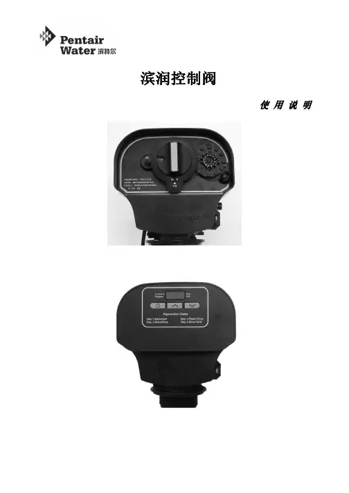
1.标准时间的设置:按下24小时控制盘上方红色时间调整按钮,使驱动齿轮咬合脱开,然后顺时针方向旋转时间控制盘,使时间盘上现在时间刻度正时间指针,再放开红色时间调整按钮使时间盘与驱动齿轮咬合。
注意:A.操作时为避免时间电机的损坏应切断电源,操作完成后再恢复供电。
B.要确认时间盘与驱动轮完全咬合后才可运行,否则将可能损坏其中的转动机构。
2.启动定时再生程序的设置:A.日期的设定,顺时针方向旋转再生日期盘,直至数字1对正中间固定轮上的箭头,将再生销旋转固定在需要的再生日期上,例:若在三、六、九、十二号螺孔拧上再生销,则今明两日没有再生,直至第三日才启动再生,以后每隔两日进行一次再生。
B.再生时间的设定,用细圆柱物插进时间控制盘中心的数字盘孔中转动数字盘使需要启动再生的时间对准时间控制盘上的黑点。
数字盘上涂有黑色的一半代表PM,白色的一半代表AM。
3.手动辅助再生:当水质硬度发生明显变化和短时间用水量增大,软水器交换容量提前耗进时,为不打乱原设定的再生程序,可以采用手动方法增加一次再生。
操作方法:按下红色时间调整按钮。
(注意:别让时间控制盘原设定数值变动),转动时间控制盘中央的手动再生旋钮,使指针到红色圆圈的位置。
然后松开红色按钮,使驱动轮与时间控制盘咬合,稍等一会软水器便开始再生。
4.再生程序的调整:A.再生周期程序在设备出厂时已预设定为164分钟,但可按当地情况之需要调整加长或者缩短。
B. 更改再生程序时间:需将再生转盘卸出来。
其方法是松开时间盘在左上角黑色的手旋螺母,然后将时间控制盘往右打开就能看见再生转盘。
卸再生转盘时,一只手固定面板上的黑旋纽,另一只手松开锁紧螺母,再生转盘就能从时间控制盘后面卸出。

全自动软化水设备操作使用手册上海华科水处理设备厂目录一、产品概述二、工作流程三、安装和运行四、设备安装示意图五、调试步骤六、故障的排除产品概述FLECK全自动控制器以闻名于世的 FLECK公司软化水技术为基础,它是将软水器的运行及再生的每一个步骤实现全自动控制,并采用时间流量或感应器等方式来启动再生。
由于 FLECK系列全自动软水设备控制系统技术成熟、操作简便、富来控制器采用了无铅黄铜阀体完全符合食品卫生要求,配以聚四氟乙烯( Teflon)涂层,活塞减小了阻力,延长了使用寿命,运行可靠。
FLECK系列全自动软水器可用于工业锅炉、热交换器、宾馆饭店、食品工业、戏衣印染、医疗卫生等行业,该产品具有自动化程度高、交换容量大、结构紧凑、能耗低、省人工、无需日常保养等特点。
系统技术参数进口压力:0.25 Mpa-0.6Mpa工作温度:2 ℃—50℃出水硬度:≤0.03mmol/L使用电源:220v /50Hz AC布置形式:双罐并联,一用一备再生方式:顺流再生操作程序:自动程序控制使用树脂:001×7强酸性阳离子交换树脂。
我公司将为用户提供完善的技术服务及售后服务。
1.工作位置工作位置罐的转换硬水从入口进入控制阀进入第一个树脂罐,经过上布水器向下穿过树脂层,成为净化水,经下布水器返回中心管,向上至控制阀经过流量计流出,第二个树脂罐进行再生准备工作。
硬水由控制阀经过连接管进入第二个树脂罐,经过树脂层,经过下布水器沿中心管向上返回,再经连接管回到控制阀经过流量计流出;第一个树脂脱离软化水流线路,准备再生。
工作流程图反洗状态盐吸位置第二罐处理好的软化水由连接管进入控制阀,向下经中心管、下布水器进入第一个树脂罐罐内,再向上经树脂层、控制阀排污口排出,第一罐的树脂床得到反洗。
慢速清洗位置第二罐处理好的软化水由连接管进入控制阀的注水器,流过射流器喷嘴产生负压,从盐箱吸入盐水进入第一树脂罐。
盐水向下流经树脂层,穿过下布水器,沿中心管向上,并从排污口排出。
目录一、产品概述 2二、工作流程图 3三、设备的系统说明 5四、设备的安装和运行 6五、设备安装示意图7六、流量型控制器调试步骤8七、时间型控制器调试步骤9八、故障排除11产品概述FLECK全自动控制器以闻名于世的FLECK公司软化水技术为基础,它是将软水器的运行及再生的每一个步骤实现全自动控制,并采用时间、流量或感应器等方式来启动再生。
调整FLECK系列全自动软水器采用时间同步电机控制全部的工作程序,在7天或12天范围内根据需要设定还原周期,二十四小时内任意选择还原时间,并可以对还原过程进行调整。
富来流量型全自动软水器采用流量控制全部工作程序,设备可连续(或间断)供水。
再生—由流量控制器自动启动再生装置,可根据需要自行设定再生程序。
由于FLECK系列全自动软水设备控制系统技术成熟、操作简便、采用了无铅黄铜阀体完全符合食品卫生要求,配以聚四氟乙烯(Teflon)涂层活塞减小了阻力,延长了使用寿命,运行可靠。
FLECK系列全自动阀门应用于工业锅炉、热交换器、大型中央空调、宾馆饭店、食品工业、洗衣印染、医疗卫生等行业,该产品具有自动化程度高、交换容量大、结构紧凑、能耗低、省人工、无需日常保养等特点。
进口压力:0.2Mpa—0.6Mpa工作温度:2℃--50℃出水硬度:≤0.03 mmoI/L使用电源:220V/50Hz AC布置形式:单罐或多罐并联再生方式:顺流再生或逆流再生操作程序:自动程序控制使用树脂:001×7强酸性阳离子交换树脂我公司将为用户提供完善的技术服务。
MODEL2510、2750、2850、3150、2900、3900工作流程图1、工作状态2、反洗状态3、再生状态4、慢速清洗状态硬水经过控制阀进入树脂罐,经树脂层处理的水通过底步的布水器,进入沿着中心升降管向上,再通过控制阀流出。
硬水进入控制阀后经过:控制阀 中心升降管向下 通过底部的布水器 经过树脂层向上 最后通过控制阀排水口排出硬水进入控制阀后,向上进入注水器,然后通过射流过程将盐罐中的还原剂吸入,带还原剂的水流向下经过树脂层进入布水器和升降管,再通过控制阀排水口排出。
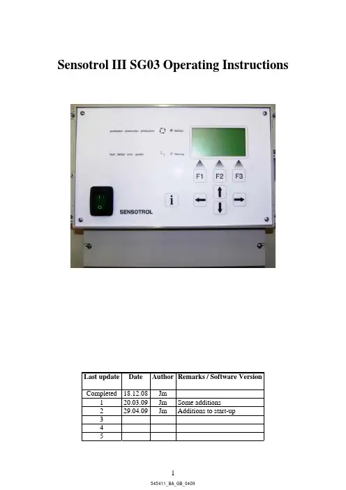
Sensotrol III SG03 Operating InstructionsVersionSoftware/update Date Author RemarksLastCompleted 18.12.08Jm1 20.03.09JmadditionsSomestart-uptoAdditions2 29.04.09Jm345Contents1Introduction (5)1.1 Description (5)1.2 Notational conventions (5)1.3 Intended use (5)2Identification (6)2.1 Designation of the device (6)2.2 Scope of supply (6)2.3 Accessories (6)3Assembly (7)3.1 Mounting conditions (7)3.2 Dimensions (7)4Electrical connection (8)4.1 Wiring at a glance (8)4.2 Terminal layout (8)4.2.1 Cable specifications (9)4.3 Wiring diagrams (9)5Operation (10)5.1 Operating status (10)5.2 Operating modes (10)5.2.1 Sensor mode (10)5.2.2 Unattended operation in sensor mode (11)5.2.3 Regeneration (11)5.2.4 Brine formation (12)5.2.5 Standby (12)5.2.6 Volume mode (12)5.2.7 Time mode (12)5.3 Switching action (13)6Instructions for use (14)6.1 Operation at a glance (14)6.2 Display and control elements (14)6.2.1 LEDs (14)6.2.2 Keyboard (14)6.2.3 Function keys (15)6.3 Entering text and figures (15)6.3.1 Menu items (15)6.3.2 Data editing (16)6.3.3 Numerical data (16)6.3.4 Selectable data (16)6.3.5 Alphanumerical data (16)6.3.6 Time of the day (17)6.3.7 Calendar (17)6.3.8 Confirmations (17)6.4 Passwords (17)7Parameters and settings (19)7.1 User menu (19)7.2 Parameters menu (20)7.2.1 Description of the parameters (21)7.3 Technician level (22)8Operation of the installation by personnel (25)8.1 Changing the operating mode (25)8.2 Parameterisation of the capacity (26)8.3 Parameterisation of digital outputs (28)8.4 Parameterisation of digital inputs (30)8.5 Entering the degree of hardness (33)8.6 Entering day and time (34)8.7 Entering locking times (35)8.8 Setting forced regeneration cycles (36)8.9 Carrying out a reset (37)8.10 Setting the triggering factor (40)8.11 Setting the operating mode (41)8.12 Setting the emergency supply (42)8.13 Setting the conductivity limits (43)8.14 Setting the time limits (44)8.15 Measuring and calibrating (45)8.16 Diagnosis (47)8.17 Protocol (49)8.18 Start-up (51)8.19 Brine circulation pump (53)8.20 Recirculation pump (56)8.21 Liquid brine (59)8.22 Chip card (62)9Malfunctions and their elimination (64)9.1 Indication and acknowledgement (64)9.2 Description of and search for malfunctions (64)9.2.1 Lack of brine (64)9.2.2 Lack of capacity (65)9.2.3 Sensor defect (65)9.2.4 Flow meter defective (66)9.2.5 Insufficient rinsing (66)9.2.6 Lack of salt (67)9.2.7 Brine filling time (67)9.2.8 Below min. flow (67)9.2.9 Max. flow exceeded (68)9.2.10 External stop (68)9.2.11 Ext. emergency stop (68)10 Disposal (69)11 Technical Appendices (70)11.1 Technical data (70)11.2 Overview of the menu (71)11.3 Wiring diagram / sample connection (74)1 Introduction1.1 DescriptionThe Sensotrol control is a sensor-controlled device that can exactly determine the depletion degree of the ion-exchange resin and, based on this, trigger and carry out REGENERATION. The controller can also be used for volume or time controlled regeneration.1.2 Notational conventionsThe following abbreviations are used throughout this manual:Lim LimitCD ConductivityT Temperaturet Time/Durationhigh Output or input not actuatedlow Output or input actuatedThe following representations are used throughout this manual:Type:Font:Example:Keys: capitals + bold LEFT, UP, DOWNLEDs: capitals + bold OPERATION,MALFUNCTION/FAULTInputs/outputs, inlets/outlets: capitals + bold INLET VALVEOperating parameters: italics cond.raww., water volum eOperating status: capitals + underlined SENSOR MODE, VOLUMEMODE, TIME MODE Operating modes: capitals + underlined OPERATION, REGENERATION Malfunctions:capitals + underlined SENSOR DEFECT1.3 Intended useThe device is intended to control sensor operated water softening units in non explosion-prone areas.• The device has been designed for top mounting and may only be operated if mounted accordingly.• The manufacturer is not liable for damages resulting from improper or unintended use.Improper or unintended use may turn the controller into a hazardous device.2 Identification2.1 Designation of the deviceCompare the nameplate at the right side of the device to the bill of materials and the following figure:EnthärtersteuerungTyp. Sensotrol III SG03S-Nr.: 00545377-AC38-xxxxElektrischer Anschluss: V/Hz 230/50Anschlussleistung: 25W2.2 Scope of supply• Device with terminal box• Cable glands:o 1 piece M20x1.5o 4 pieces M16x1.5o 4 pieces M12x1.5• Stopper:o 2 pieces M16x1.5o 3 pieces M12x1.5• Terminal block plan (inside the terminal box cover)• Operating instructions• Bill of materialsPlease inform your supplier if you notice that parts are missing.2.3 AccessoriesFor the Sensotrol control the following accessories are available:• PC-Visualisation• Ethernet-Interface module• Profibus-Interface module3 Assembly3.1 Mounting conditionsWorking temperature range: 0 to 35 °C (32 to 95 °F), humidity, non-condensing.Caution!• Please provide sufficient cooling of the installation in order to avoid heat accumulation. • Make sure there is sufficient distance to strong magnetic fields.• Environment according to protection category IP65.3.2 DimensionsThe controller is delivered inside a Bopla casing RCPM 2500 for top mounting (217x257x133 mm).4 Electrical connection4.1 Wiring at a glanceWarning!Note that the entire electric connection may only be carried out while the device is disconnected from the mains.Caution!• The protective earth connection must be carried out before any other connection. Danger may occur if the PE wire is interrupted.• Before performing the start-up, make sure that the supply voltage corresponds to the value indicated on the nameplate (right side of casing).• Combining low safety voltage and voltage presenting a risk of electrocution at the relays is not permitted.• For the mains line, an overcurrent protection (nominal current ≤ 16 A) is required.Note:Please also observe the terminals plan inside the terminal box cover.4.2 Terminal layoutTerminal Operation Type Comment1 230V phase 2230V neutral 3Supply voltagePESupply of the controller. (fuse: 4A)4230V phase 5 230V neutral 6Mains output PESupply of the switching outputs (fuse: 4A)7NC contact 8Root9Universal output 1 NO contact Voltage-freemax. 24VDC/1A, 250VAC/4A10PE 11No 12Operation valve of filter 1 BV1 Lo 24 VAC max. 300 mA13PE 14No 15 La 16 Lb 17 Pilot valve of filter 1 PV1 Lo 24 VAC max. 300 mA18 PE 19No 20 Operation valve of filter 2BV2 Lo 24 VAC max. 300 mA21 PE 22No 23 La 24 Lb 25 Pilot valve of filter 2PV2 Lo 24 VAC max. 300 mA26 Root27Universal output 2(Operation message) NO contact Voltage-freemax. 24VDC/1A, 250VAC/4A 28 Root29Universal output 3(Regeneration message) NO contact Voltage-freemax. 24VDC/1A, 250VAC/4A 30 Root31Universal output 4(error message) NO contactVoltage-freemax. 24VDC/1A, 250VAC/4ADistance (galv. isolation)32 Root33 Universal output 5(pulse output dosing pump) NO contact Open collector output 24 VDC max. 15 mA 34 Resin temp. 35 Resin temp.36 Resin conduct. A37 Resin conduct. B, water conduct. A38 Conduct. sensor water/resinfilter 1Water conduct. B39 Resin temp. 40 Resin temp.41 Resin conduct. A42 Resin conduct. B, water conduct. A43 Conduct. sensor water/resinfilter 2Water conduct. B44 GND45 Pulse input 46 Flow meter+24 VDC For Hall effect sensor or REED switch47 GND 48 Universal input 1 (lack of salt switch) Input For voltage-free contact 49 GND 50Universal input 2InputFor voltage-free contact4.2.1 Cable specificationsTerminalsCable min. Cable max.Cable typeSupply voltage 3x1.0 mm² 3x1.5 mm² NYM-J/Ölflex 110Mains output3x0.75 mm² 3x1.5 mm² NYM-J/Ölflex 110Universal output 13x0.75 mm² 3x1.5 mm² NYM-J/Ölflex 110Operation valve of filter 13x0.5 mm² 3x0.75 mm² Ölflex 110 Pilot valve of filter 1 5x0.5 mm² 5x1.0 mm² Ölflex 110 Operation valve of filter 23x0.5 mm² 3x0.75 mm² Ölflex 110 Pilot valve of filter 2 5x0.5 mm² 5x1.0 mm² Ölflex 110Universal output 2 2x0.5 mm² 2x1.0 mm² NYM-J/Ölflex 110Universal output 3 2x0.5 mm² 2x1.0 mm² NYM-J/Ölflex 110Universal output 4 2x0.5 mm² 2x1.0 mm² NYM-J/Ölflex 110Universal output 5 2x0.14 mm² 2x0.5 mm² LiYY/Ölflex 110 Conduct. sensor filter 1 6x0.14 mm² 6x0.34 mm² LiYCY Conduct. sensor filter 2 6x0.14 mm² 6x0.34 mm² LiYCY Flow meter3x0.14 mm² 3x0.5 mm² LiYY Universal input 1 2x0.14 mm² 2x0.75 mm² LiYY Universal input 22x0.14 mm²2x0.75 mm²LiYY4.3 Wiring diagramsIn the appendix you will find examples of the wiring configuration.5 Operation5.1 Operating statusFilters A and B can each have the following operating modes:• OPERATION• STANDBY• REGENERATION• ERROR (FAULT)The Sensotrol controller has been developed chiefly as a sensor control system which can be used to accurately establish depletion of the ion-exchange resin so that REGENERATION can be subsequently triggered and carried out. The controller can also be used for volume or time controlled regeneration.5.2 Operating modes5.2.1 Sensor modeA regenerated filter can be put into OPERATION immediately after REGENERATION. A depleted filter can not be put into OPERATION before it has been regenerated. In sensor mode, automatic adjustment takes place at the beginning of each operational phase whenever a volume of water in litres equal to three times the capacity in m³ · °d has passed through the filter. As long as the first adjustment of a filter has not been completed, the respective filter is displayed as greyed out on the screen. At the first commissioning the filters must be calibrated and the filters should be displayed normally on the screen. Conductivity in the resin bed (CDR) and in the soft water (CDW) is continuously calculated.The processor calculates the following triggering factor (TF) at short intervals:CDRTF = -------------- x 100JustCDRwhere CDRJust represents the resin conductivity during adjustment. The triggering factor during adjustment is therefore 100%. Tests have shown that conductivity decreases by about 35% when the resin changes from a regenerated to a depleted state. During complete depletion, resin conductivity is still at 65% of the level during adjustment and so the smallest possible triggering factor is TF = 65%.When water passes the filter, the control unit compares the momentary value of the triggering factor with a fixed value TF0 between 65 and 85% (generally 80%). If the triggering factor remains below the value TF0 (t-TF0) for five minutes then REGENERATION is initiated. The triggering criterion TC charts the course of the triggering factor between 100 % and the fixed value TF0 as a linear function for the range 100% to 0%, i.e. if levels go below the value TC=0%, then REGENERATION is initiated (after a five minute delay).If no water flows, the triggering criterion is no longer monitored. This means that a conductivity drift within the resin granule, caused by diffusion during stop times, cannot initiate the regeneration process. If the soft water conductivity (CDW) changes during OPERATION, then the conductivity in the resin bed (CDR) which activates regeneration must also change. The dependency CDR on the CDW has been shown in tests and is saved as a data record in the control unit. The value of CDRJust, which corresponds to the new value of CDW, can thus be calculated and used to determine the current triggering criterion.5.2.2 Unattended operation in sensor modeIn order to control the functioning of the flow meter, the last triggering criterion is kept until termination of the adjustment. If the FLOW METER is working, the new triggering criterion is applied upon termination of the adjustment.If the FLOW METER is defective, the adjustment is not completed due to the absence of the flow meter signal. When the triggering criterion is reached before termination of the adjustment, the controller recognises the FLOW METER to be defective.If the sensors are working, the installation OPERATES according to standard instructions.In case of a sensor defect, the soft water conductivity and/or the resin conductivity is not recorded. The controller recognises this and displays an error message.5.2.3 RegenerationIf the installation is run in volume or time mode, the regeneration is carried out according to an adjustable timetable for the duration of each regeneration step. The sensor mode combines a time-controlled process and monitoring of rinse water conductivity. The details of the procedure are as follows:1. Backwash (BW):This is carried out for a preset, fixed period of time (backwash t).2. Brine draw/slow rinse (BD/SR):During BRINE DRAW, there is a check to see whether the high conductivity of brine is registered on the water sensor within a preselectable time (brine wait. t). This high conductivity must then be measured for a second preselectable time (minimum time for the brine draw "min.t.brn.dr.") on the water sensor. If the criteria for this two-step brine test are not fulfilled, the LACK OF BRINE alarm is activated. The slow rinse stage continues until the rinse water conductivity lies constantly under 1,800 µS/cm (CD-SR) for a 60 second period. If this level of conductivity has not been reached once the set time (brine draw t) has come to an end, the process is stopped.3. Fast rinse:This is carried out for a preset, fixed period of time (fast rinse t). If the rinse water conductivity is still above 1,800 µS/cm (CD-FR) at the end of this time, the controls remain in fast rinse mode until the conductivity falls below this level and five more minutes have passed (LACK OF RINSING error).Once REGENERATION is completed, the regenerated filter is in STANDBY. Connecting a BRINE PUMP can reduce the time needed for brine formation (brine form t), which takes 300 minutes without a circulation pump, to about 60 minutes because of forced circulation in the brine tank. The BRINE PUMP is to be connected to the UNIVERSAL OUTPUT 1 (terminals 7, 8, 9). Set the brine formation time to 60 minutes (brine form t). During brine formation, REGENERATION can be initiated but not started. The delay (in minutes) until the start of the REGENERATION process is shown in the LCD.5.2.5 StandbyUpon termination of the REGENERATION the filter switches to STANDBY. A switch to OPERATION takes place when the other filter starts to REGENERATE.5.2.6 Volume modeREGENERATION is initiated depending on the volume, i.e., as soon as thesoft water volume (m³) = capacity (°dH x m³) / max. hardness (°dH)for the filter in operation is reached.Note!In the event that the FLOW METER is defective, it is possible that hard water enters the system. The FLOW METER is monitored in sensor mode only.5.2.7 Time modeRegardless of the depletion degree of the resin, a REGENERATION of the filter in OPERATION is initiated as soon as a defined time interval (to be defined in the technician level, forced regeneration has elapsed.Note!When the unit runs in time mode, the depletion degree of the resin is not detected. It is thus possible that hard water enters the system.Switching pointRegenerated resin Depleted resinConductivity Resin/WaterWater conductivityCD = Conductivity in the resin/water mixture Vs = soft water amount produced 80 % = triggering factor6 Instructions for use6.1 Operation at a glanceThe controller is easy to understand and allows commissioning the unit almost without the operating manual for many applications. The start-up wizard will guide you through all of the important settings as soon as the device has been switched on.It shows the setting limits and standard settings for the respective parameters on the screen. Below these you will find explanations on the controller for the elements that are not clearly described through text or by selection lists. We reserve the right to make changes that serve technical progress.6.2 Display and control elementsThe operator interface consists of a graphic display (128x64 pixel), 7 keys and an LED for OPERATION and FAULT each. It also has an acoustic alarm.6.2.1 LEDsThe LEDs show the installation's status OPERATION (green) and FAULT (red).6.2.2 KeyboardThe controller is operated by 4 cursor keys and 3 function keys (F1, F2, F3). The cursor keys have the following functions:Î (RIGHT) Selection of one decimal place within an edit fieldÍ (LEFT) Selection of one decimal place within an edit fieldÏ (UP) Menu selection, option selection, selection of one digit within an edit fieldÐ (DOWN) M enu selection, option selection, selection of one digit within an edit fieldF1 (ESC) Function key 1 (often used as ESC key)F2Function key 2F3 (ENTER) Function key 3 (often used as ENTER key)6.2.3 Function keysOperation is mainly carried out with the function keys (F1, F2, F3). The functions of the keys are indicated through the icons in the lower display section.The icons that are most frequently used are shown below:Terminate function/menu, abort setting (= ESC)Select function/menu, save setting (= ENTER)Answer "yes" to a questionAnswer "no" to a questionDisplay report menuDisplay settings menu6.3 Entering text and figures6.3.1 Menu itemsThe menu consists of several items in a list (arranged one below the other) that can be longer than the number of items displayed on the screen.A menu item is selected with the arrow on the left side of the screen. The arrow is moved with the UP and DOWN keys and moved to the menu item of your choice. The marked menu item is then selected with the F3/ENTER key. If the list of menu items is longer than the part displayed on the screen, the controller scrolls automatically.Note:• Most of the menus have a hierarchical structure, i.e., upon selection of a menu item, another submenu opens.• You can usually leave a menu by pressing the F1/ESC key (return to normal level).6.3.2 Data editingData are normally edited via a special screen, where the parameters, their admissible value range and the standard value are shown.Any editing process may be aborted without saving the changed value by pressing F1 (ESC). When editing parameters, there is differentiation between the following five data types:6.3.3 Numerical dataNumerical editing is carried out to adjust the operating parameters and to set the calibration parameters. Numerical editing works like programming a decade switch.The digit to be changed is selected with the cursor (a block in the display) and set to the desired value by pressing the UP / DOWN keys as often as necessary. By means of the LEFT / RIGHT keys, the cursor can be moved to the other digits so that these can be modified as well. The value indicated is stored using the F3 (ENTER) key.6.3.4 Selectable dataIn some cases an option can be selected (operating modes, operating statuses). Upon selection of the option, the operator can scroll through all further options with the UP / DOWN keys. The displayed selection is confirmed with the ENTER key.6.3.5 Alphanumerical dataThe message texts can be edited alphanumerically. The procedure is identical to that of numerical editing, but it is possible to select numbers and characters with the UP and DOWN keys.6.3.6 Time of the dayEditing is carried out as described for numerical data, but a time in the HH:MM format is selected. It is possible to edit any time from 00:00 to 24:00 (the 24 h mode allows definition of a complete one-day time span). .The adjustment to summertime or wintertime is carried out automatically.6.3.7 CalendarEditing is carried out as described for numerical data, but a date in the DD:MM:YY format is selected. The year is set with only two digits (20xx is assumed).6.3.8 ConfirmationsFor safety reasons and to avoid erroneous settings, some functions require confirmation. The following screen is used for this purpose.By confirming with F3/Enter the selected function is carried out. By pressing F1/Esc the function is aborted.6.4 PasswordsThe different menus, functions and settings are accessible via 4-digit, numerical passwords. The following two hierarchical access levels are differentiated.Access level Name oflevelPresetpasswordPassword necessary for...1 User level 1234 user and parameter levels3 Technicianlevel3456 technician level and sublevelsThe password for the level indicated on the screen (or superior level password) must be entered and confirmed with F3/Enter.If a wrong password is entered or if the password entry is aborted with F1/Esc, the access is denied.Note:• The passwords can be changed in the parameter menu and in the technician level.• It is possible, when a password is asked for, to enter the password of a higher level. Since the access to the superior level is granted until the menu is exited, passwords will not have to be re-entered if additional functions carried out.7 Parameters and settings7.1 User menuMenu Parameter Format/Unit Selection/LimitsDefault setting U1 InformationU1.1 Total amount filter 1 xxxx m³< Q tot filter 1 > ---U1.2 Total amount filter 2 xxxx m³< Q tot filter 2 > ---U1.3 Max. amount filter 1 xxxx m³< Q max filter 1 > ---U1.4 Max. amount filter 2 xxxx m³< Q max filter 2 > ---U1.5 Conduct. raw water filter 1 xxxx µS/cm< CDW filter 1 > ---U1.6 Conduct. raw water filter 2 xxxx µS/cm< CDW filter 2 > ---U1.7 Conduct. resin filter 1 0 - 1024< CDR filter 1 > ---U1.8 Conduct. resin filter 2 0 - 1024< CDR filter 2 > ---U1.9 Type <Sensotrol> ---U1.10 Language -Deutsch- English- Français- Italiano- Nederlands- E spañol Deutsch (German)U1.11 Audio signal - Off- OnOff U1.12 Software version < > --- U1.13 System version < > --- U1.14 Param. version < > --- U1.15 Calib. version < > ---U1.16 Autom.Summer/Wintertime - Off- OnOnU1.17 Start of summer time < > --- U1.18 Start of winter time < > --- U2 Operating modeU2.1 - Operation filter 1- Operation filter 2- Regen. filter 1- Regen. filter 2--- U3 System timeU4 Parameters Access to the parameter level7.2 Parameters menuMenu Parameter Format/unit Selection/limitsDefault setting P1 Locking time AP1.1 Start 00:00–00:0000:00–24:00 00:00P1.2 End 00:00–00:0000:00–24:00 00:00P2 Locking time BP2.1 Start 00:00–00:0000:00–24:00 00:00P2.2 End 00:00–00:0000:00–24:00 00:00P3 Forced regeneration xx d00–99 00P4 Hardness rangeP4.1 °dH min xx.x °dH0.0–99.9 5.0P4.2 °dH max xx.x °dH0.0–99.9 40.0P5 Operating mode - Sensor mode- Volume mode- Time mode Sensor operationP6 Emerg. supply - Hard water- Switch offSwitch offP7 Conduct. limits (super password will be asked for when modifying data)P7.1 cond.brine_wait xxxxµS/cm600–800 600P7.2 condct.slow rns xxxx µS/cm1000–2000 1800P7.3 condct.fast rns xxxx µS/cm1000–2000 1800P7.4 dct.sensor xxxµS/cm0–100 20P7.5 dct.sensr xxxxµS/cm2000–50005000 P8 Time limits/param.P8.1 backwash t xx min2–30 9P8.2 brine draw t xxx min60–180 120P8.3 fast rinse t. xx min5–30 19P8.4 brine form t xxx min0–500 300P8.5 brine wait. t xx min2–50 40P8.6 min.t.brn.dr. xxxmin5–50 10P8.7 cond.brine_wait xxxs5–999 60P8.8 brine fill. t xx min5–99 30P9 Technician level Access to the technician levelP10 User password 4-digit code0000–9999 12347.2.1 Description of the parameters• P7.1 brine wait. t: the scaled conductivity value of the water that must be reached for the period P8.5 during the brine draw regeneration step is displayed.• P7.2 condct.slow rns: the scaled conductivity value of the water that must be reached for the period P8.7 during the slow rinse regeneration step is displayed (downscaled).• P7.3 condct.fast rns: water conductivity value that the measured value must fall below during the regeneration phase fast rinse.• P7.4 dct.sensor and P7.5 dct.sensr: limits of the measuring range of the conductivity probe.• P8.1 backwash t: duration of the regeneration phase backwash.• P8.2 brine draw t: max. duration of the regeneration phase brine draw.• P8.3 fast rinse t.: min. duration of the regeneration phase fast rinse• P8.4 brine form t: time set for brine formation.• P8.5 brine wait. t: period of time during which the high conductivity value of the brine (P7.1) must be detected during the regeneration phase brine draw.• P8.6 min.t.brn.dr.: min. duration of the regeneration phase brine draw.• P8.7 t cd.low sl.r: min. period of time during which the conductivity must be below the limit (P7.2) during the regeneration step slow rinse• P8.8 brine fill t.: max. time for the filling of the liquid brine tank.7.3 Technician levelDefault setting Menu Parameter Format/Unit Selection/LimitsS1 InputsS1.1 pulse input xxx.xx pulse/l0.01–999.99 34.50NOCS1.2 univ.DI1 logic - NC contact- NO contactS1.3 univ.DI1 func. - permanentpermanent- pulselack of saltS1.4 univ. DI1 text Freely programmablemessage textS1.5 univ.DI1reaction - no reactionno reaction- message only (analogous to"1" in the malfunction matrix)- emerg. switch-off (NAZ)- system off- suppressionregeneration- initiationregeneration- brine fillingS1.6 univ. DI1 active - alwaysalways- stand-by- operation- backwash- brine draw/slow rinse- fast rinse- hard water production if lackof capacity- lock iflack of capacity- error stop- locking time- below min. flow- no flow- lack of brine- sensor defect- lack of cap.- lack of rinsingS1.7 univ. DI1 delay xxx s0–999 0S1.8 univ. DI2 logic analogue univ.dig. input1S1.9 univ.DI 2 func. analogue univ.dig. input1S1.10 univ. DI 2 text analogue univ.dig. input1S1.11 univ.DI2reaction analogue univ.dig. input1S1.12 univ. DI2 active analogue univ.dig. input1S1.13 univ. DI2 delay analogue univ.dig. input1Menu Parameter Format/Unit Selection/Limits Default settingS2 OutputsS2.1 univ. DO1 - stand-by F1- operation F1- backwash F1- brine draw / slow rinse F1- fast rinse F1- standby F2- operation F2- backwash F2- brine draw / slow rinse F2- fast rinse F2- error stop- system off- recirculation- brine recirc.- brine filling- lack of brine- hrd w.if low cap- l ock if low cap.- locking time- no flow- sensor defect- lack of cap.- lack of rinsing- univ.dig. input1- univ.dig. input2 0 / P / I0 / P / I0 / P / I0 / P / I0 / P / I0 / P / I0 / P / I0 / P / I0 / P / I0 / P / I0 / P / I0 / P / I0 / P / I0 / P / I0 / P / I0 / P / I0 / P / I0 / P / I0 / P / I0 / P / I0 / P / I0 / P / I0 / P / I0 / P / I0 / P / IS2.2 univ. DO2 analogous to univ. DO1S2.3 univ. DO3 analogous to univ. DO1S2.4 univ. DO4 analogous to univ. DO1S2.5 funct. univ. DO5 - 0 / P / I- pulse output/IS2.6 *pulse output/I xx.xx pulse/l0.01–99 1S2.7 °univ. DO5 analogous to univ. DO1S3 Sensor type - d32/d50- ¾"d32/d50 S4 Capacity xxxx m³ °dH20–10.000 200S5 Max. flow xx.xx m³/h0.01–99.99 20.00S6 Recirculation xx.xx m³/h0.01–99.99 0.05S7 TF0 (triggering factor) xx %65–90 80S8 t-TF0 (delay TF0) xxx s 0–999 300S9 Meas./calibr.S9.1 CDW1 µS/cm Input of actual valueS9.2 CDW2 µS/cm Input of actual valueS9.3 calibrate analogue input (super passwordrequested)Calibration of curves。

产品使用说明书全自动软水器苏州康凌环保设备有限公司目录一、安装要求---------------------------------------------------------2二、安装步骤---------------------------------------------------------2三、软水器试调运行---------------------------------------------------3四、软水器在生程序设置-----------------------------------------------3五、软水器标准工作流程-----------------------------------------------4六、控制器程序设置---------------------------------------------------4七、软水器维护-------------------------------------------------------5八、故障原因---------------------------------------------------------5一、安装要求①、进水压力应在0.2-0.6MPa,当水源压力无法满足要求时,可安装增压水泵提高进水压力。
如果压力过高,应安装减压阀来控制进水压力。
②、进水温度应在5-45℃之间,此装置不允许在冰点状态下工作.③、电源采用交流200V/50Hz,运行中需保证电源不间断,并不可被其开关切断.④、软水器应安装在牢固的平台上,附近有畅通的下水,并留有足够的操作和维修空间。
二、安装步骤1)、先将树脂罐.盐罐就位于坚实的基础上,并保证罐体水平2)、把下布水器牢固安装在中心管底端,然后插入到树脂罐中央,在中心管上端低于罐口0.5mm处截断并导角,然后用胶带封住中心管口,以防树脂漏入。
3)、将树脂均匀地装入树脂罐中,树脂装填完,取下中心管的封口胶带,将中心管上部及树脂罐端面用水冲洗并擦干净,中心管及控制器密封圈处涂上硅油。
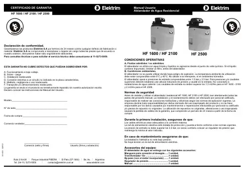
CONDICIONES OPERATIVASA. Fluidos admitidos / no admitidos.El ablandador se utiliza con agua limpia y líquidos no agresivos desde el punto de vista químico. Si el liquido contiene impurezas, instalar un filtro, antes del ablandador.B. Condiciones ambientales.El ablandador no se puede utilizar donde haya peligro de explosión. La temperatura ambiente de utilización debe estar comprendida entre 0°C y 40°C. No utilizar a la intemperie, ni en ambientes húmedos.El ablandador opera a presiones de entrada comprendidas entre 1.5 bar y 3.5 bar. Para presiones y/o caudales superiores deberá instalarse una válvula reductora de presión y caudal en la entrada. No conectarlo ainstalaciones de agua caliente. Los caudales de entrada no deben superar los 1,5 m3/Hs para el HF 1600 - 2100y 2 m3/Hs para el HF 2500.Normas de seguridadAntes de instalar y utilizar el ablandador residencial HF 1600, HF 2100 o HF 2500, leer atentamente todas las partes del presente manual. La instalación y el mantenimiento deben ser efectuado por personal calificado, responsable de realizar las conexiones hidráulicas y eléctricas según las normas de aplicación vigentes. La empresa declina toda responsabilidad por daños derivado del uso inapropiado del producto y no se haceresponsable por los daños causados por mantenimientos o reparaciones efectuadas por personal no calificado y/o piezas de repuesto no originales. La utilización de repuestos no originales, alteraciones o uso inapropiado causara la perdida de validez de la garantía, que comprende un período de 24 meses a partir de la fecha de compra.Durante la primera instalación, asegurese de que:Los cables eléctricos sean adecuados a la corriente máxima.La red de alimentación eléctrica esté dotada de protección y puesta a tierra conforme a las normas presión de entrada no debe superar los 3.5 bar, en canso contrario colocar un regulador de presión que mantenga la misma al valor indicado.En caso de mantenimiento asegurarse de que:La instalación hidráulica no este bajo presión.No haya tensión en la red de alimentación eléctrica.Accesorios del equipo:El ablandador de agua se entrega con los siguientes accesorios: Manguera para conexión al desagüe......1 unidad.Transformador 12v ...................................1 unidad.By-pass (con el meter incorporado) .......1 unidad.Regulador de presión...............................1 unidad.Manual .......................................................1 unidad.Parque Industrial PIBERA I El Pato (CP 1893)Bs. As.I Argentina5273-5050I *********************.arI IRuta 2 Km39 I T el: (54-11) Declaración de conformidad.Garantizamos los productos Elektrim S.A por termino de 24 meses contra cualquier defecto de fabricación o material. Elektrim S.A se compromete a reemplazar o reparar sin cargo todas las piezas que de acuerdo a nuestro examen, demuestren haber sido originalmente deficientes.Para consultas técnicas o para solicitar el servicio técnico debe comunicarse al 11-5273-5050.ESTA GARANTÍA NO CUBRE DEFECTOS QUE PUEDAN SOBREVENIR POR:A. Funcionamiento a bajo voltaje.B. Sobre - cargaC. Instalación inadecuadaD. Conexión eléctrica a un circuito no indicado en la placa característica.E. Maltrato, negligencia o uso inadecuado.F. Transporte y/o almacenamiento inadecuado.La garantía se anula si el producto es tentativamente reparado sin nuestra autorización escrita.Declaro conocer las instrucciones del Manual del Usuario.Modelo___________________________________________N° de serie________________________________________Fecha de compra:__________________________________Comercio vendedor____________________________________________________ _______________________ Comercio (sello y firma) Usuario (firma y aclaración)331-031 120721HF 2500HF 1600 / HF 2100Guía de resolución de problemasInstalaciónAntes de proceder a la instalación del equipo, retire el protector de embalaje que retiene el tanque dentro del salero. Cierre la llave general de entrada de agua y vaciar de agua la instalación.Montaje by-passEl conjunto by-pass se compone del cuerpo compacto, 2 trabas, 2 racords, 2 juntas planas y 1 contador volumétrico1. Quite las dos trabas que sujetan y unen el cuerpo compacto del by-pass a los racords.2. Extraiga los adaptadores del cuerpo compacto.3. Monte las juntas planas en la zonas roscadas de la válvula delante de los racords.4. Rosque los racords a la válvula.5. Monte el cuerpo compacto del by-pass a los racords roscados a la válvula.6. Vuelva a colocar las trabas en ambas conexiones.7. Conecte el terminal de la válvula en la clavilla del contador volumétrico. La uña debe quedar encajada hasta el fondo.Nota: El controlador volumétrico mide el caudal de agua a la salida del ablandador. Va colocado en el orificio de salida del agua de la válvula. Controle que el mismo encuentre dentro del by-pass, que no se caiga.Elementos del ablandador1. Filtro de partículas (Opcional): Contiene un elemento filtrante que tiene la misión de retener las partículas en suspensión del agua.2. Válvula: Este elemento es el que contiene los mecanismos para realizar la regeneración automática de las resinas mediante un sistema programado, por tiempo o por volumen de agua consumida.3. Drenaje. Dejar un espacio de aire entre la línea de drenaje y el agua residual a fin de evitar la posibilidad de que las aguas residuales sean devueltas al ablandador.4. Salero: Recipiente acumulador de sal. Su capacidad le permite una importante autonomía en la reposición de la sal y es donde se produce la salmuera necesaria para el proceso de regeneración de la resina. En su interior se encuentra la botella de resina: Recipiente contenedor de resina de intercambio iónico, que realizan el proceso de descalcificación.5. Electrobomba. Se debe instalar, para que el ablandador pueda realizar la regeneración, cuando la presión de la instalación no este comprendida entre 1.5 bar y 3.5 bar.6. By-pass.7. Regulador de presión (Importante: Respetar el sentido del flujo del agua con la flecha indicada en el regulador).Puesta a punto1. En posición de “by pass” abra la llave de paso, así como una canilla de agua fría después del ablandador, dejando circular el agua durante unos minutos para eliminar la suciedad de las tuberías. Una vez que estén limpias, cierre la canilla.2. Coloque el by pass en la posición de servicio y deje que se llene el ablandador. Cuando se pare el flujo, abra una canilla de agua fría cercana y deje correr el agua hasta que se haya eliminado el aire del equipo.3. Una vez realizada esto, coloque la sal gruesa o entre fina hasta la mitad del salero, por única vez 10 Lts (aprox un balde) como se indica mas adelantes en el dibujo de la pagina 5.4. Enchufe la válvula en una toma de corriente con el transformador que trae el equipo .5. Coloque la válvula en posición de servicio y compruebe que no haya pérdidas en ninguna de las juntas.6. Verifique la programación de la válvula y determine el volumen de servicio de agua entre regeneraciones a programar, si el equipo no fue programado.7. Realice una regeneración manual del equipo. Esto tiene como objeto eliminar el aire que pueda quedar en la botella de resina. Deje un tiempo de aproximadamente un minuto en cada paso de la regeneración hasta llegar a la posición de servicio nuevamente y el display marca .8. A partir de este momento, el equipo ya se encuentra listo para su uso.El by-pass tiene tres posiciones:CERRADO: No hay entrada de agua en la válvula ni realiza el by-pass.BY PASS: Posición de by-pass; agua de salida con la dureza de entrada. EN SERVICIO: Toda el agua entra en la válvula; agua de salida descalcificada.HF 2500Medida de la dureza del agua:Tiempos de los ciclos de regeneración (vienen determinado de fabrica)Los tiempos de los ciclos de regeneración han sido programados por el fabricante del ablandador. Sin emitirá un pitidoprograma H, que corresponde con los días máximos entre regeneraciones.H-00D: La función queda desactivada. H-01D: Se hará una regeneración cada 1 día .H-02D: Se hará una regeneración cada 2 días. H-03D: Se hará una regeneración cada 3 días. Ajuste el valor con el mismo Regeneración manualdesaparezca.cuando la válvula no esta en posición marca -00-.3S Entrada de agua Salida de aguaEMantenimiento.Compruebe periódicamente que el reloj del ablandador coincida con la hora real del día y el nivel de sal del depósito, el nivel de sal recomendado sería un poco más de la mitad del depósito. Evite que el nivel baje de unos 20 cm desde la base del depósito ya que entonces la regeneración no se realizaría correctamente. Al rellenar de sal el depósito tenga la precaución de no echar sal en el flotante de salmuera ni agregar agua, ya que el equipo lo realiza automáticamente.SPasos para una correcta instalación:1. Elija un lugar adecuado para la instalación del equipo, que disponga de una toma de corriente eléctrica de 230V-50Hz (para conectar el transformador provisto), con suministro ininterrumpido y con una conexión al desagüe en su proximidad que no supere la altura del ablandador.2. Compruebe que las tuberías existentes estén limpias, sin incrustaciones de cal ni hierro. La instalación debe estar en conformidad con la legislación vigente.3. Instale un filtro de partículas a la entrada de ablandador para protegerlo de las impurezas que lleva el agua.4. Es recomendable Instalar un juego de llave a la entrada, adicional al del by-pass, así se asegura de mantener el suministro de agua en caso de necesitar desinstalar el ablandador.5. Conecte los tubos en la entrada y la salida de agua del ablandador según indican las flechas grabadas en la válvula o by-pass colocado en la parte posterior.6. Conecte la salida de desagüe de la válvula, al desagüe de su casa mediante el tubo suministrado en el kit de conexión al desagüe. NOTA: Nunca debe insertar la línea de drenaje directamente en una rejilla, línea de alcantarillado o sifón. Siempre se debe dejar un espacio de aire entre la línea de drenaje y el agua residual a fin de evitar la posibilidad de que las aguas residuales sean devueltas al ablandador.Entrada de aguaSalida de aguaRacordCuerpo By-passJunta planaConexióncontroladorvolumétricoContadorvolumétricoTrabaRacordTapónHF 2500CuerpoBy-passRacordConexióncontroladorvolumétricoContadorvolumétricoTrabaTrabaTrabaJuntaplanaHF 1600 / HF 2100Conexión decontrolador volumétricoEHF 1600 / HF 2100Cableconexión12vSalidadesagüeConexión desalmueraCableswitchHF 2500ESEESSE SSEEESS- Cable switch: Atención, no conectar a 220 V.- Cable conexión 12 V: conectar al transformador provisto.RacordCableswitchConexión decontrolador volumétricoSalidadesagüeConexiónde salmueraCableconexión12vEntrada de agua Salida de aguaconfiguración del tipo de regeneración recomendada:A -- 01 = regeneración retardada (la regeneración se hará siempre a una hora prefijada, una vez agotado el volumen de agua).A -- 02 = regeneración instantánea (la regeneración se hará al llegar al volumen de agua fijado, independientemente de la hora)A -- 03 = regeneración inteligente retardada (la regeneración se hará siempre a una hora prefijada)A -- 04madrugada, que es la hora a la que viene prefijada.aparecerá la indicación F seguida de dos números, que corresponde al “intervalo de contra lavado”, es decir, el número de regeneraciones en las que la válvula no hará un contra lavado. Para válvulas contra-corriente no es necesario realizar un contra lavado en cada regeneración. F-00: Se hará un contra lavado en cada regeneración.F-01: Se dejará una regeneración sin contra lavado. F-02: Se dejarán dos regeneraciones sin contra lavado.F-03: Se dejarán tres regeneraciones sin contra lavado.Metros cúbicos entre regeneraciones (De acuerdo a la dureza del agua).Rellenado del salero para un buen funcionamiento1. Abra la tapa.2. Verifique el nivel sal.3. Completar con sal gruesa o entre fina hasta el nivel indicado.4. Cierre la tapa.y nivel mínimo DimensionesEsquema de instalación básica para tanque elevadoAblandador HFLlaves de paso colector distribuciónFlotanteLlave cortegeneral Tanque elevadoLlave de paso purgador tanqueNivel max. de sal resina (*)desagoteNivel min. de sal(*) Cantidad resina: HF1600: 12,5 litros /HF2100: 20 litros / HF2500: 22 litros.Succión de salmuera DíasProgramación del reloj de la válvula1. El icono indica que el teclado está bloqueado. Para desbloquearlo y entrar en el modo de funcionamiento manual y realizar cambios de programación, pulse las teclas al mismo tiempo hasta que el icono desaparezca.3. Pulse de nuevo la tecla . El icono aparecerá y el valor de las horas parpadearán. Mediante losajustar minutos.Programación de la regeneración Esquema de instalación para tanque cisternaImportante: ante cualquier duda respecto de los esquemas de instalación que figuran en este manual, o ante la necesidad de efectuar una instalación diferente a las mismas, se recomienda comunicarse con Elektrim.Esquema de instalación con cisterna para tanque elevadoTanqueCisternaa los serviciosAblandador HFLlaves de pasocolector distribuciónFlotantegeneral Tanque elevadoLlave de paso purgador tanqueretención 1 1/4"Descripción del Display y TeclasEsquema de instalación para tanque cisterna con bomba sumergible。
For personal use only in study and research; not for commercial useFor personal use only in study and research; not for commercial use更换滨特尔爱惠浦净水器PP棉流程网络上关于自己换PP棉的介绍极少,写篇博文详细说明下自己的经验,希望能给看到、搜到的朋友提供点方便。
材料准备:1、购买PP棉和扳手。
这点要注意,淘宝上各家价格相差很大,有的卖到30元,有的只有十几块,其实这东西成本本来就不高,没必要找太贵的买,找个信誉高点的就行了。
但记得一定要店家送10寸的过滤筒扳手,没有扳手,更换时会极为痛苦的,切记,切记。
2、塑料水盆、干毛巾、螺丝刀等。
更换步骤:(请严格按照顺序更换)1、关闭净水器进水水阀(即下图中红色的把手)。
这个水阀一般与水管冷水三通装在一起。
最好也将三通一道关了。
2、打开净水器出水龙头。
就是平常放水的龙头。
3、按住前置滤筒上的红色按钮。
这个按钮的目的是泄压,压下去的时候,会有水冒出来,要放在盆里面。
我拍照的时候,筒还挂着在橱柜壁上。
正常情况下,应该将筒取下来,放在盆里按红色按钮。
为了下一步轻松下,这个要多按一会儿,4-5分钟吧,没有水再冒出来了,就差不多了。
4、拧开前置滤筒。
这是最难的一步,要看好方向,是将蓝色盖子逆时针拧开,,一定要用扳手。
我时间都耗费在这上面了,拧得手都发紫。
不过,后来摸索出一个好点的方法。
就是坐在板凳上,然后将扳手套到筒上面,并夹到两腿中间,同时,让另一个人抓紧扳手。
接着,自己两只手一起用力拧盖子。
拧盖子时,最好将上面的铁片取下来,防止用力过大,扯坏了螺丝孔。
5、更换PP棉,并拧紧滤筒。
打开进水阀门,打开龙头,放水几分钟,检查有无漏水。
注:爱惠浦PRO4的主滤芯过滤精度比较高,换PP棉时容易进入空气,最好通水时先排气,否则容易导致出水量小或不出水。
化水培训资料10T/h纯水系统操作说明编写单位:宜兴市立场水处理设备有限公司日期:2013年05月一:工艺简述江苏联合水泥有限公司主要生产水泥为主的一家专业单位,由于在生产过程中排出大量含热量的烟气,所以增加了余热发电设备,以备自身使用。
余热发电锅炉为低压锅炉,工作压力约为1.35MPa,锅炉补给水设备采用预处理+反渗透+混床的工艺,原水初步选用当地自来水,正常运行后选用喝水净化及消毒后的水;保证经过工艺处理后的水能达到国家规定的低压热水锅炉进水水质«GB1576-85»中含盐量及硬度的要求。
1.进水水质及水量:电导率:≤500μs/cm 浊度:≤5 度CODcr:≤4mg/L 进水水量: 17 m3/h2. 产水水质:锅炉补给水系统出水必须符合«低压锅炉水质标准»(GB1576-2001),见下表,并满足以下要求:25℃.产水量: 10 m3/h膜脱盐率:≥95%(三年内)电导率:〈0.2μS/cmPH: 7.5~9.2其余:2.正常运行所需化学药品规格3.1杀菌剂名称:次氯酸钠状态:液体化学成分:NACLO纯度:≥10%3.2进口高效阻垢剂(美国ARGO公司)名称:MDC220化学成分:聚合磷酸盐状态:液体纯度:化学纯3.2清洗剂用酸化学成分:柠檬酸状态:固体纯度:分析纯3.4清洗剂用碱化学成分:NaOH状态:固体纯度:分析纯3.5氢氧化钠(混床用)状态:液体浓度≥30%NaOH液体,碳酸钠含量≤0.8%Na2CO3,氯化钠含量2.0~5.0%NaCl,三氧化二铁含量≤0.01%Fe2O 3.3.6盐酸(混床用)浓度≥31%HCl液体,含铁量≤0.01%Fe,硫酸盐含量≤0.007%SO4-2,砷含量≤0.0001%As.3.7调整PH值用碱化学成分:氨水状态:液体浓度:≥10%二:工艺流程简图↓↓↓↓↓→混床再生工艺流程:a 酸再生工艺纯水箱→再生泵→喷射器→流量计→混床→排放↑卸酸泵→高位碱贮罐→浓酸箱b 碱再生工艺纯水箱→再生泵→喷射器→流量计→混床→排放↑卸碱泵→高位碱贮罐→浓碱箱工艺流程简述原水为当地自来水或本单位预处理后的河水,进水原水箱,再由原水泵直接输送到砂过滤器,同时在过滤器进水口投加杀菌剂及絮凝剂。
一操作规范1.安装要求:1) 软水器要应安放在牢固的水泥平台上,附近应设有排水道,且排水管的排水量应和软水器的排水量相配。
2) 储盐箱(盐筒)应安放在靠近树脂罐的地方,两者间距不大于200MM,并尽量缩短吸盐管的长度。
3) 软水器与加热设备直接相连时,应保持3米以上的管距并安装单向阀。
4) 储盐罐的放置应便于再生剂的补充。
5) 设备附近应当留有操作及检查修的空间。
2.管道连接:1) 管道的连接请参照当地施工规范的有关内容。
2) 按照控制阀口径连接进口出水管。
3) 进出水管应装有手动阀门,进出水管之间应装有旁通阀,出水管应安装取样阀,进水管道建议安装Y型过滤器。
4) 尽量缩短排水管的长度,减少弯度,控制阀与排水道距离不超过2米。
5) 排水管与排水道连接时,必须使排水管与排水道的水面保持一定的空间,防止活水被子虹吸返回软水器。
6) 排水管道中不得安装各类阀门。
7) 盐水管的连接一定要保持良好的密封性,否则会影响软水器的再生效果。
8) 在盐水罐的预留孔位上安装溢流口,并配接头塑料管(用户自购),引至排水道.。
9) 各种管道都必须设不定期独立的支架,不允将管道的重力,应力传给控制阀。
3.电气连接:1) 确认控制阀的电气参数与电源一致。
2) 将插头插入与相配插座。
3) 电源插座不应受附近开关的控制。
4.树脂的装填:1) 树脂装前应将中心管收集管(带布水器)放入树脂罐中央,(此时应用胶带封住中心管,防止石英砂和树脂进入中心管)2) 将石英砂按规定的量丛中心管周围的空隙投入树脂罐,并使之在罐底埔平。
3) 将处理好的树脂(阳树脂)按照规定的装填量丛中心管周围投入树脂罐。
4) 上述操作应使中心管始终保持在树脂罐的中央位置。
5) 取下中心管的封口胶带。
6) 将控制阀的承插口对正中心管,小心地顺时针转动控制阀。
(注意:在旋转须在中心管口部涂擦润滑剂,一定要确保中心管插入阀体)直至控制阀旋紧在罐体接口上。
4 调试篇1) 缓慢地打开进水阀至1/4开启处,(注意:阀门开启过快树脂会流失)此时可以听到空气从排水管排出的声音。
软水器使用说明书一、工作原理水中含有Ca2+、Mg2+盐类,这是形成硬度(结垢)的物质。
为了防止在金属受热面上产生水垢,须将水中的Ca2+及Mg2+用离子交换剂不能生成水垢阳离子(Na+及H+)相互交换,从而得到软化。
当原水经过钠离子交换剂层时,水中的Ca2+及Mg2+等阳离子与交换剂中的Na+相遇,水中的Ca2+、Mg2+被吸在交换剂上,Na型离子交换剂转变成Ca型离子交换剂,而离子交换剂上原来的Na+进入水中,从而除去了水中的Ca2+和Mg2+,当Na型离子交换剂完成变成Ca型离子交换剂时,这种反应停止了,此时称之为离子交换剂的失效。
为了恢复离子交换剂的交换能力,将盐液通过Ca型离子交换剂,使Ca型离子交换剂又变成Na型离子交换剂而恢复交换能力,又重新投入使用。
二、软水器的操作运行1、运行前的准备:(1)软水器及其管道按照“软水器管网系统原理图”将罐内全部排净,然后打开装料孔或人孔装进阳离子交换剂001×7-MB,(φ1000软水器先装高度750mm石英砂,然后装交换剂)交换剂装至上观察孔中心,封闭装料孔。
(2)新装的离子交换剂,首先进行逆流再生,之后方可运行。
2、操作运行:操作运行按照“操作系统图”及下表顺序:运行-再生-反洗-正洗进行。
1#软水器操作顺序注:未注明即为“关”2#软水器操作顺序注:未注明即为“关”1#、2#软水器同时运行开①①'④④'其余关闭。
三、一般技术要求:1、原水进水压力宜控制在0.2~0.5MPa之间。
2、再生液浓度一般为6~10%之间,再生流速调整在4~6米适宜。
再生时间一般在40~50分钟,但要根据交换器失交效程度而定。
3、反洗时水流速一般控制在12~18米/时为宜,反洗时间一般为15~20分钟至出水澄清为止。
4、正洗:正洗流速同运行时的压力和流速:时间为排出水的指标完全符合国家标准为止。
5、盐液池分浓盐池和稀盐池,所用盐为工业用盐。
将工业盐放入浓盐池加水溶解,经过滤后进入稀盐池,按照再生液要求进行稀释。
目录一、产品概述 2二、工作流程图 3三、设备的系统说明 5四、设备的安装和运行 6五、设备安装示意图7六、流量型控制器调试步骤8七、时间型控制器调试步骤9八、故障排除11产品概述FLECK全自动控制器以闻名于世的FLECK公司软化水技术为基础,它是将软水器的运行及再生的每一个步骤实现全自动控制,并采用时间、流量或感应器等方式来启动再生。
调整FLECK系列全自动软水器采用时间同步电机控制全部的工作程序,在7天或12天范围内根据需要设定还原周期,二十四小时内任意选择还原时间,并可以对还原过程进行调整。
富来流量型全自动软水器采用流量控制全部工作程序,设备可连续(或间断)供水。
再生—由流量控制器自动启动再生装置,可根据需要自行设定再生程序。
由于FLECK系列全自动软水设备控制系统技术成熟、操作简便、采用了无铅黄铜阀体完全符合食品卫生要求,配以聚四氟乙烯(Teflon)涂层活塞减小了阻力,延长了使用寿命,运行可靠。
FLECK系列全自动阀门应用于工业锅炉、热交换器、大型中央空调、宾馆饭店、食品工业、洗衣印染、医疗卫生等行业,该产品具有自动化程度高、交换容量大、结构紧凑、能耗低、省人工、无需日常保养等特点。
进口压力:0.2Mpa—0.6Mpa工作温度:2℃--50℃出水硬度:≤0.03 mmoI/L使用电源:220V/50Hz AC布置形式:单罐或多罐并联再生方式:顺流再生或逆流再生操作程序:自动程序控制使用树脂:001×7强酸性阳离子交换树脂我公司将为用户提供完善的技术服务。
MODEL2510、2750、2850、3150、2900、3900工作流程图1、工作状态2、反洗状态3、再生状态4、慢速清洗状态硬水经过控制阀进入树脂罐,经树脂层处理的水通过底步的布水器,进入沿着中心升降管向上,再通过控制阀流出。
硬水进入控制阀后经过:控制阀 中心升降管向下 通过底部的布水器 经过树脂层向上 最后通过控制阀排水口排出硬水进入控制阀后,向上进入注水器,然后通过射流过程将盐罐中的还原剂吸入,带还原剂的水流向下经过树脂层进入布水器和升降管,再通过控制阀排水口排出。
5600SE全自动软化水设备安装、运行及维护手册目录一、产品概述二、工作流程图三、设备的安装和运行四、设备安装示意图五、FLECK5600控制器的调试步骤六、FLECK56SE控制器的调试步骤七、FLECK56SE控制器全面编程及相关代号的意义列表八、故障排除产品概述首先感谢您使用本公司的全自动软化水设备!为着方便您的使用,我们编写了该产品的客户手册,您的认真阅读和理解一定能为产品的良好使用打下基础。
5600系列自动软水器分为时间周期型和流量周期型两种控制方式,用户可以根据当地水质及用户对于水质的要求来进行选择。
本产品广泛应用于蒸汽和热水锅炉、热交换设备、食品加工、造纸印刷、洗衣印染、家庭、宾馆饭店、医疗制药、纯水制备预处理等行业。
我公司将给用户提供完善的技术及售后服务。
自动软水器技术参数:入口水压:0.2Mpa-0.6Mpa工作温度:2-50℃电源型式:220V/50Hz AC电源功率:3W出口硬度:≤0.03mmol/L再生方式:动态顺流再生或逆流再生树脂型号:001×7强酸性阳离子交换树脂盐 耗:<160-240g/mol (根据水质情况)FLECK5600/56SE 控制器工作流程图说明:FLECK5600和56SE 控制器的水流过程略为不同,但原理一致。
1、 工作状态2、预清洗(5min )3、反洗(10min)4、吸盐(50min )5、慢洗6、快洗7、稳层清洗 8、盐箱充水设备的安装和运行一、 一般要求a 、 软水器应安装在牢固的水泥平台上,附近应设有排水沟;b 、 盐罐的安放应靠近树脂罐,并尽量缩短吸盐管的长度;c 、 环境温度不能低于2℃或高于50℃;d 、 软水器与加热设备直接相连时,应保持3米以上的管段并安装单向阀;e 、 要便于再生剂的补充;f 、 设备附近应当留有操作及维修空间。
二、控制器安装与树脂装填a 、 装填前应将升降管(带下布水器)放入树脂罐中央低于罐口0.5mm 处截断并导角此后应用胶带封住升降管口,(为防止石英砂和树脂进入升降管); b 、 将石英砂沿升降管周围空隙投入树脂罐,并使之在罐底铺平;硬水经控制器进水口向下流过中心管、下布水器,向上流经树脂层,流出排水口,进行反洗。
软化水设备说明书一、软化水简介软化水:经软化处理后的水,即除去了部分或全部钙、镁离子的水。
软化水不易与肥皂产生浮渣,而硬水相反。
天然软水一般指雨、雪水。
人工软化水是经软化处理的钙盐和镁盐含量降至为 1.0~50 毫克/升后得到的软化水。
(工业上采用截然不同的标准,工业上一般只有硬度<1的水称作软水,1-10之间都经常笼统地称为硬水,硬度>10的水也多称为高硬水)二、软化水设备工作原理和科学依据1、水的硬度主要由其中的阳离子:钙(Ca2+)、镁(Mg2+)离子构成。
当含有硬度的原水通过交换器的树脂层时,水中的钙、镁离子被树脂吸附,同时释放出钠离子,这样交换器内流出的水就是去掉了硬度离子的软化水,当树脂吸附钙、镁离子达到一定的饱和度后,出水的硬度增大,此时软化水设备会按照预定的程序自动进行失效树脂的再生工作,利用较高浓度的氯化钠溶液(盐水)通过树脂,使失效的树脂重新恢复至钠型树脂。
2、硬度如何转化成软水硬水转换软化水的化学方程式:钙的去除:CaCO3+2Na-R=Ca-R+Na2CO3Ca(HCO3)2+2Na-R=Ca-R+2NaHCO3镁的去除:MgCO3+2Na-R=Mg-R+Na2CO3Mg(HCO3)2+2Na-R=Mg-R+2NaHCO3三、软化水的好处1、对人体的好处:软化水可将肌肤细胞内的污物彻底清除,延缓皮肤衰老,使清洗后的皮肤无紧绷感,光泽细腻。
由于软水中含有丰富的有机矿物质,具有较强的去污力,只需少量的卸妆膏,就可取得100%的卸妆效果,因此软水是爱美人士的必需品。
软水用于经常性的沐浴,可帮您解除皮肤干燥、皮癣、皮屑苦恼,恢复正常的弹性皮肤。
皮肤炎症,是由于肥皂、洗涤剂、摩擦、木材、皮革、刺激性佐料细菌、干燥空气等作用下产生的,发生湿疹或手足裂纹时,若常用软水清洗,就可驱除湿疹,愈合裂纹,还您柔软、富有光泽的手、足。
软化水还可以有效抑制真菌。
发生皮外伤、冻伤、烧伤之类意外时,先用软水洗净患处后,并以软水浸湿脱脂棉、纱布、毛巾等,轻擦患部,可快速愈合伤口,并且使烧伤引起的浮肿马上消失,这是由于软水具有促进细胞组织再生的作用。
软水机说明书北京恒源水处理设备公司软水机磁化渗透软水机具有出水量大,水质软化效果好,设备性能稳定,全自动智能化运行,实现自动再生、动态溶盐功能等众多特点,不仅可以满足高尚家庭沐浴、洗衣、清洁及家用热水器、热水炉等方面优质供水之需,为您提供更清洁、更柔润的家庭用水,也可为商家、机关、学校等企事业单位提供高质量的软化水。
【性能参数】产品型号DIOA-04(RM) 系列名称前置预处理处理工艺软化树脂最大额定流量 4.0吨/小时最大允许水通量≥3000升/小时(0.15MPa.25℃) 外壳材质食品级PP工作压力0.15-0.5MPa 适用水源市政自来水接口尺寸1/2英寸/ 直径12毫米【产品特点】高效交换进口高品质软化树脂,交换能力强,不易破损,使用寿命长达30年;顺流再生再生充分,随时保证最佳品质的软水,同时省盐省水,延长树脂使用寿命。
反洗树脂反洗冲掉树表层截留和结聚悬浮物质和一些破碎树指,松动压紧树指层,增强再生效果;正洗除盐通过正洗清除树指中残留的盐液,清洗至出水合格,压紧树脂层,以达到最佳软化效果;防漏抗击加强玻璃钢罐,防渗漏,抗冲击,内层PE材质,外层玻璃钢,双层加厚,杜绝渗漏现象;自动再生全程电脑控制软水和再生进程,省时省心;分层树脂高效分层树脂床,软化效果更佳;【产品机理】∙运行(IN SERV.):源水在一定压力和流速下流经本软水机后,离子交换树脂中所含的活性基团中的Na+ 单元与水中的Ca 2+ 、Mg 2+等阳离子进行交换,使水中的Ca 2+、Mg 2+等离子的浓度降低,从而使水质得到软化。
∙反洗(Backwash):离子交换树脂饱和后,再生之前要先进行反洗,其目的一是冲洗去掉树脂表层截留和结聚的悬浮杂质和一些破碎树脂,二是松动压紧的树脂层,有利于树脂颗粒在再生时与再生液充分接触,为离子交换树脂再生提供良好条件。
∙吸盐再生(Brine):一定浓度和流量的盐液流经整个离子交换树脂层,将饱和的树脂再生,使其恢复原有的软化交换能力。