eclipse画UML类图 (1)
- 格式:doc
- 大小:1.29 MB
- 文档页数:40
UML各种图例面向对象的问题的处理的关键是建模问题.建模可以把在复杂世界的许多重要的细节给抽象出.许多建模工具封装了UML(也就是Unified Modeling Language ™),这篇课程的目的是展示出UML的精彩之处.UML中有九种建模的图标,即:∙用例图∙类图∙对象图∙顺序图∙协作图∙状态图∙活动图∙组件图∙配置图本课程中的某些部分包含了这些图的细节信息的页面链接.而且每个部分都有一个小问题,测试一下你对这个部分的理解.为什么UML很重要?为了回答这个问题,我们看看建筑行业.设计师设计出房子.施工人员使用这个设计来建造房子.建筑越复杂,设计师和施工人员之间的交流就越重要.蓝图就成标准文档为了这个行业中的设计师和施工人员的必修课.写软件就好像建造建筑物一样.系统越复杂,参与编写与配置软件的人员之间的交流也就越重要.在过去十年里UML就成为分析师,设计师和程序员之间的“建筑蓝图”.现在它已经成为了软件行业的一部分了.UML提供了分析师,设计师和程序员之间在软件设计时的通用语言.UML被应用到面向对象的问题的解决上.想要学习UML必须熟悉面向对象解决问题的根本原则――都是从模型的建造开始的.一个模型model就是根本问题的抽象.域domain就是问题所处的真实世界.模型是由对象objects组成的,它们之间通过相互发送消息messages来相互作用的.记住把一个对象想象成“活着的”.对象有他们知道的事(属性attributes)和他们可以做的事(行为或操作behaviors or operations).对象的属性的值决定了它的状态state.类Classes是对象的“蓝图”.一个类在一个单独的实体中封装了属性(数据)和行为(方法或函数).对象是类的实例instances.用例图用例图Use case diagrams描述了作为一个外部的观察者的视角对系统的印象.强调这个系统是什么而不是这个系统怎么工作.用例图与情节紧紧相关的.情节scenario是指当某个人与系统进行互动时发生的情况.下面是一个医院门诊部的情节.“一个病人打电话给门诊部预约一年一次的身体检查.接待员找出在预约记录本上找出最近的没有预约过的时间,并记上那个时间的预约记录.”用例Use case是为了完成一个工作或者达到一个目的的一系列情节的总和.角色actor是发动与这个工作有关的事件的人或者事情.角色简单的扮演着人或者对象的作用.下面的图是一个门诊部Make Appointment用例.角色是病人.角色与用例的联系是通讯联系communication association(或简称通讯communication)标准文档角色是人状的图标,用例是一个椭圆,通讯是连接角色和用例的线.一个用例图是角色,用例,和它们之间的联系的集合.我们已经把Make Appointment作为一个含有四个角色和四个用例的图的一部分.注意一个单独的用例可以有多个角色.用例图在三个领域很有作用.决定特征(需求).当系统已经分析好并且设计成型时,新的用例产生新的需求标准文档∙客户通讯.使用用例图很容易表示开发者与客户之间的联系.∙产生测试用例.一个用例的情节可能产生这些情节的一批测试用例.类图类图Class diagram通过显示出系统的类以及这些类之间的关系来表示系统.类图是静态的-它们显示出什么可以产生影响但不会告诉你什么时候产生影响.下面是一个顾客从零售商处预定商品的模型的类图.中心的类是Order.连接它的是购买货物的Customer和Payment.Payment有三种形式:Cash,Check,或者Credit.订单包括OrderDetails(line item),每个这种类都连着Item.标准文档UML类的符号是一个被划分成三块的方框:类名,属性,和操作.抽象类的名字,像Payment是斜体的.类之间的关系是连接线.类图有三种关系.关联association-表示两种类的实例间的关系.如果一个类的实例必须要用另一个类的实例才能完成工作时就要用关联.在图中,关联用两个类之间的连线表示.标准文档标准文档为了简单地表示出复杂的类图,可以把类组合成包packages.一个包是UML上有逻辑关系的元件的集合.下面这个图是是一个把类组合成包的一个商业模型.dependencies关系.如果另一个的包B改变可能会导致一个包A改变,则包A依赖包B.包是用一个在上方带有小标签的矩形表示的.包名写在标签上或者在矩形里面.点化线箭头表示依赖对象图Object diagrams用来表示类的实例.他们在解释复杂关系的细小问题时(特别是递归关系时)很有用.这个类图示一个大学的Department可以包括其他很多的Departments.标准文档这个对象图示上面类图的实例.用了很多具体的例子.UML中实例名带有下划线.只要意思清楚,类或实例名可以在对象图中被省略.标准文档每个类图的矩形对应了一个单独的实例.实例名称中所强调的UML图表.类或实例的名称可能是省略对象图表只要图的意义仍然是明确的.顺序图类图和对象图是静态模型的视图.交互图是动态的.他们描述了对象间的交互作用.顺序图将交互关系表示为一个二维图.纵向是时间轴,时间沿竖线向下延伸.横向轴代表了在协作中各独立对象的类元角色.类元角色用生命线表示.当对象存在时,角色用一条虚线表示,当对象的过程处于激活状态时,生命线是一个双道线.消息用从一个对象的生命线到另一个对象生命线的箭头表示.箭头以时间顺序在图中从上到下排列.标准文档协作图协作图也是互动的图表.他们像序列图一样也传递相同的信息,但他们不关心什么时候消息被传递,只关心对象的角色.在序列图中,对象的角色放在上面而消息则是连接线.标准文档对象角色矩形上标有类或对象名(或者都有).类名前面有个冒号(:).协作图的每个消息都有一个序列号.顶层消息的数字是1.同一个等级的消息(也就是同一个调用中的消息)有同样的数字前缀,再根据他们出现的顺序增加一个后缀1,2等等.状态图对象拥有行为和状态.对象的状态是由对象当前的行动和条件决定的.状态图statechart diagram显示出了对象可能的状态以及由状态改变而导致的转移.标准文档我们的模型例图建立了一个银行的在线登录系统.登录过程包括输入合法的密码和个人账号,再提交给系统验证信息.登录系统可以被划分为四种不重叠的状态:Getting SSN, Getting PIN, Validating, 以及 Rejecting.每个状态都有一套完整的转移transitions来决定状态的顺序.标准文档状态是用圆角矩形来表示的.转移则是使用带箭头的连线表示.触发转移的事件或者条件写在箭头的旁边.我们的图上有两个自转移.一个是在Getting SSN,另一个则在上Getting PIN.初始状态(黑色圆圈)是开始动作的虚拟开始.结束状态也是动作的虚拟结束.事件或条件触发动作时用(/动作)表示.当进入Validating状态时,对象并不等外部事件触发转移.取而代之,它产生一个动作.动作的结果决定了下一步的状态.活动图活动图activity diagram是一个很特别的流程图.活动图和状态图之间是有关系的.状态图把焦点集中在过程中的对象身上,而活动图则集中在一个单独过程动作流程.活动图告诉了我们活动之间的依赖关系.对我们的例子来说,我们使用如下的过程.“通过ATM来取钱.”这个活动有三个类Customer, ATM和 Bank.整个过程从黑色圆圈开始到黑白的同心圆结束.活动用圆角矩形表示.标准文档标准文档标准文档。
淮海工学院计算机工程学院实验报告书课程名:UML理论及实践题目:实验二绘制用例图和类图班级:D计算机081学号:**********名:**一、实验目的与要求(1)理解actor、Use case的概念及作用,能标识Actor之间、Use case之间、Actor 和Use Case之间的关系;(2)理解类的内部结构及类间的关系(Association、Generalization、dependency、realize、Aggregation、composition,...)(3)学会应用Rose/RSA绘制Use case图和类图,在图中正确绘制各种图形元素、表示元素间的相互关系。
二、实验内容(1)可以以“图书信息管理”或"*****管理系统"为主题,绘制其Use case图和类图。
(2)要求所绘制的图形应与所描述的主题语义一致。
三、实验步骤1.以“网店管理系统”为主题,绘制其Use case图和类图。
2.描述绘制的Use case图和类图。
四、实验结果雇员图一网店管理Use Case图图中包含四个活动者:个人顾客、顾客、协作顾客、雇员。
包含五个Use case:分别为“浏览商品”、“添加商品”、“删除商品”、“商品选购”、“订货作业线”。
个人顾客、顾客、协作顾客之间存在泛化关联。
Use case “浏览商品”、“添加商品”、“删除商品”、“商品选购”存在包含关联。
顾客、雇员分别于五个Use case “浏览商品”、“添加商品”、“删除商品”、“商品选购”、“订货作业线”存在使用关联。
图二网上商店的类图矩形框“订货”、“订货作业线”、“顾客”、“个人顾客”、“协作顾客”、“雇员”、“产品”、均表示对象类。
将每个对象类图框分割成3个分隔框,其中分别列出了该对象类的类名、属性和操作。
例如在对象类“顾客”中,有两个属性name(顾客名)和address(地址),一个操作creditRating()(信誉度分级)。

UML时序图的绘制步骤与技巧分享UML(Unified Modeling Language)是一种用于软件开发的建模语言,其中的时序图是一种重要的图表类型。
时序图可以展示系统中各个对象之间的交互和消息传递,有助于开发人员更好地理解系统的行为。
在本文中,我们将分享一些绘制UML时序图的步骤和技巧,希望对读者有所帮助。
步骤一:确定参与者和对象在绘制时序图之前,首先要确定参与者和对象。
参与者是指与系统进行交互的外部实体,可以是人、其他系统或者硬件设备。
对象则是系统内部的实体,可以是类、组件或者模块。
明确参与者和对象的身份和职责,有助于后续绘制时序图时的思路清晰。
步骤二:确定交互顺序时序图是按照时间顺序展示对象之间的交互和消息传递,因此在绘制时需要确定交互的顺序。
可以根据需求文档或者系统设计来确定交互的顺序,确保时序图的逻辑正确和完整。
步骤三:绘制生命线和参与者生命线是时序图中的基本元素,用于表示对象的生命周期。
在绘制时序图时,需要为每个对象绘制一个垂直的虚线,这条虚线称为生命线。
同时,还需要添加参与者,即系统的外部实体。
通过绘制生命线和参与者,可以清晰地展示对象和参与者之间的关系。
步骤四:绘制消息消息是时序图中的核心元素,用于表示对象之间的交互和消息传递。
绘制消息时,需要确定消息的发送者和接收者,并用实线箭头表示消息的方向。
可以使用不同的箭头样式来表示不同类型的消息,如同步消息、异步消息、返回消息等。
通过合理地绘制消息,可以清晰地展示对象之间的交互流程。
步骤五:添加约束和注释时序图不仅可以展示对象之间的交互,还可以添加约束和注释来进一步说明系统的行为。
约束可以用于限制对象的行为,如前置条件、后置条件等。
注释可以用于解释时序图中的细节或者提供额外的说明。
合理地添加约束和注释,可以使时序图更加清晰易懂。
技巧一:合理使用分组在复杂的系统中,对象之间的交互可能非常复杂。
为了更好地展示交互过程,可以使用分组来将相关的对象和消息进行分组。

目录1.类图和对象图的概念2.类图的组成3.使用Rose创建类图4.对象图5.使用Rose创建类图案例分析类图和对象图详解对于类图和对象图来说我们需要了解的是类图和对象图的概念,类图的组成,使用Rose创建类图和对象图。
当然最重要的是如何使用Rose创建类图案例分析。
具体的创建通过选课管理系统的简单用例说明创建类图和对象图的方法和具体的过程。
下面是我对类图和对象图学习过程的一个整理,一些资料是直接拿过来直接用的。
希望能对你的学习有一点点的帮助吧。
类图和对象图的概念1. 类的含义类图(Class diagram)显示了系统的静态结构,而系统的静态结构构成了系统的概念基础。
类图,就是用于对系统中的各种概念进行建模,并描绘出它们之间关系的图。
在大多数的 UML 模型中,我们可以将这些概念的类型概括为以下四种,分别是:(1) 类(2) 接口(3) 数据类型(4) 构件在类图中,具体来讲它一共包含了以下几种模型元素,分别是:类、接口、依赖关系、泛化关系、关联关系以及实现关系。
类图可以创建约束、注释和包等。
2. 对象图的含义对象图中包含对象(Object)和链(Link)。
其中对象是类的特定实例,链是类之间关系的实例,表示对象之间的特定关系。
3. 类图在项目开发中的作用类图的作用是对系统的静态视图进行建模。
当对系统的静态视图进行建模时,通常是以以下三种方式来使用类图。
(1)为系统的词汇建模。
(2)模型化简单的协作。
(3)模型化逻辑数据库模式。
在设计数据库时,通常将数据库模式看作为数据库概念设计的蓝图,在很多领域中,都需要在关系数据库或面向数据库中存储永久信息。
系统分析者可以使用类图来对这些数据库进行模式建模。
4. 对象图在项目开发中的作用对象图作为系统在某一时刻的快照,是类图中的各个类在某一个时间点上的实例及其关系的静态写照,可以通过以下几个方面来说明它的作用:(1)说明复杂的数据结构。
对于复杂的数据结构,有时候很难对其进行抽象成类表达之间的交互关系。
UML类图画法全程解析本节向⼤家介绍⼀下UML类图画法,主要包括UML类图元素和关系画法,希望通过本⽂的介绍,你对UML类图画法有⼀定的认识。
软件设计起步:UML类图画法学习设计模式,画UML类图是基础,通过UML类图,能更好地和⼤家交流,也能很容易就表达出⾃⼰的设计想法,它就好⽐普通话,是⼀种标准语⾔。
现在流⾏的主要⼯具有两种:RationalRose和MicrosoftVisio,这两种⼯具都⽐较易⽤,选择哪种⼯具就看个⼈的喜好了。
本⼈对Microsoft 的软件⽐较有好感,所以⾃然MicrosoftVisio2003是我的⾸选。
UML类图常⽤元素。
类:类是⼀种复杂的数据类型,它是将不同类型的数据和与这些数据相关的操作封装在⼀起的集合体。
CPerson是⼀个抽象类,它是不能被实例化的,⽽CFamily可以被实例化。
接⼝:接⼝是被调⽤者调⽤的⼀组操作⽅法。
其实CPerson也可以作为接⼝。
UML类图中常见的⼏种关系。
泛化(Generalization):⼀句话,就是继承的表⽰。
是is-a的关系。
依赖(Dependency):UML类图画法中依赖是⼀种使⽤关系,它说明⼀个事物规范的变化可能影响到使⽤它的另⼀个事务,但反之则不然。
依赖关系的表⽰法是虚线箭头,箭头尾部的元素依赖箭头头部的元素,是use-a的关系。
关联(Association):⽤于描述类与类之间的连接,是has-a的关系。
聚合(Aggregation):聚合是关联的特例。
如果类与类之间的关系具有“整体和局部”的特点,则把这样的关联称为聚合。
它往往有“包含”,“由……组成”的意思。
我这⾥举的都是平时UML类图画法常⽤的⼏种情况,当然UML还有很多知识我没有了解,⽐如关联就有许多种。
本节向⼤家介绍⼀下UML类图符号,只有掌握了UML符号的意义,你才能很好的使⽤,本节从⼋个⽅⾯向⼤家介绍UML类图符号,希望通过本节的学习你对UML类图符号有初步的认识。

UML协作图的绘制方法与应用场景UML(Unified Modeling Language)是一种用于软件系统建模的标准化语言,它提供了一套丰富的图形符号和规范,用于描述软件系统的结构、行为和交互。
其中,UML协作图是一种重要的图示工具,用于表示系统中的对象之间的合作关系和消息传递。
一、UML协作图的绘制方法UML协作图主要由对象和消息组成。
对象表示系统中的实体,消息表示对象之间的交互。
在绘制UML协作图时,可以按照以下步骤进行:1. 确定系统中的对象:首先,需要确定系统中的对象,并对其进行命名和分类。
对象可以是具体的实体,也可以是抽象的概念。
2. 绘制对象:在UML协作图中,对象通常用矩形表示,矩形中包含对象的名称和类型信息。
可以使用不同的颜色或图标来区分不同类型的对象。
3. 确定对象之间的关系:根据系统需求,确定对象之间的合作关系。
常见的关系有关联、依赖、聚合、组合等。
可以使用箭头和线条来表示不同的关系类型。
4. 绘制消息:在UML协作图中,消息通常用带箭头的线条表示,箭头指向消息的接收者。
消息可以是同步的或异步的,可以包含参数和返回值的信息。
5. 添加约束和注释:根据需要,可以在UML协作图中添加约束和注释,以提供更详细的说明和解释。
二、UML协作图的应用场景UML协作图在软件系统开发过程中有着广泛的应用场景,以下是一些常见的应用场景:1. 系统设计:在系统设计阶段,可以使用UML协作图来描述系统中不同对象之间的协作关系,以及消息的传递方式。
通过绘制UML协作图,可以清晰地展示系统的整体架构和交互过程,有助于团队成员的理解和沟通。
2. 接口设计:在设计接口时,可以使用UML协作图来表示接口之间的消息传递和协作关系。
通过绘制UML协作图,可以明确接口之间的依赖关系和调用顺序,有助于接口的设计和实现。
3. 系统调试:在系统调试过程中,UML协作图可以帮助开发人员追踪和定位问题。
通过绘制UML协作图,可以清晰地展示系统中对象之间的交互过程,有助于排查错误和调试代码。

UML用例图的绘制技巧UML(Unified Modeling Language)是一种用于软件系统的建模语言,它提供了一套标准的图形符号和规范,用于描述系统的结构和行为。
其中,用例图是一种常用的图示工具,用于描述系统的功能需求和用户之间的交互。
在绘制UML用例图时,我们需要掌握一些技巧,以确保图示的清晰、准确和易于理解。
本文将介绍一些常用的绘制技巧,帮助读者更好地应用UML用例图。
1. 确定系统边界在绘制用例图之前,我们需要明确系统的边界。
系统边界是指系统与外部实体之间的分界线,它定义了系统的范围和界限。
确定系统边界是用例图绘制的第一步,它可以帮助我们理清系统的功能和参与者之间的关系。
2. 识别参与者参与者是指与系统进行交互的外部实体,可以是人、其他软件系统或硬件设备等。
在绘制用例图时,我们需要识别所有的参与者,并将它们表示为图中的符号。
参与者通常以人的图标或简单的图形表示,以便于理解和识别。
3. 确定用例用例是指系统的功能需求,描述了系统与参与者之间的交互过程。
在绘制用例图时,我们需要明确系统的所有用例,并将它们表示为图中的椭圆形符号。
每个用例应该具有一个简洁明确的名称,以便于理解和识别。
4. 确定参与者和用例之间的关系参与者和用例之间的关系是用例图的核心内容。
在绘制用例图时,我们需要明确参与者与用例之间的关系,并将它们表示为图中的连线。
常见的关系有:关联关系(Association)、包含关系(Include)、扩展关系(Extend)等。
这些关系可以帮助我们理清系统的功能和参与者之间的交互流程。
5. 添加扩展和包含关系扩展和包含关系是用例图中的重要概念,用于描述用例之间的依赖关系。
扩展关系表示一个用例可以在另一个用例的基础上进行扩展,而包含关系表示一个用例可以包含另一个用例。
在绘制用例图时,我们可以使用带箭头的虚线来表示扩展关系,使用带箭头的实线来表示包含关系。
6. 使用注释和说明在绘制用例图时,我们可以使用注释和说明来提供额外的信息和解释。

UML协作图的绘制步骤解析UML(Unified Modeling Language)是一种用于软件工程的建模语言,它提供了一套标准化的图形符号,用于描述系统的结构和行为。
其中,协作图是一种重要的图形表示方式,用于展示系统中各个对象之间的协作关系。
本文将解析UML协作图的绘制步骤,帮助读者更好地理解和应用这一工具。
1. 确定需求和目标:在绘制UML协作图之前,我们首先需要明确系统的需求和目标。
这包括了系统中涉及的对象、它们之间的交互方式以及所要实现的功能。
通过明确需求和目标,我们可以更好地规划协作图的绘制过程。
2. 选择适当的对象:在绘制UML协作图时,我们需要选择适当的对象来表示系统中的各个参与者。
这些参与者可以是具体的人、组织或者其他系统。
根据需求和目标,我们可以确定哪些对象是必要的,以及它们之间的关系。
3. 确定消息传递方式:协作图的核心是描述对象之间的消息传递方式。
在绘制协作图时,我们需要确定消息的发送者和接收者,并标明它们之间的关系。
消息可以是同步的,即发送者等待接收者的响应;也可以是异步的,即发送者不需要等待接收者的响应。
4. 绘制参与者和消息:在确定了对象和消息传递方式之后,我们可以开始绘制协作图。
首先,我们可以绘制参与者,使用矩形表示,并在矩形内部写明参与者的名称。
然后,我们可以使用箭头表示消息的传递方向,并在箭头上标明消息的名称。
5. 添加细节和约束:协作图可以包含更多的细节和约束,以帮助读者更好地理解系统的协作方式。
例如,我们可以使用注释框来解释特定消息的含义,或者使用约束条件来限制消息的传递方式。
这些细节和约束可以通过文本的形式添加到协作图中。
6. 完善协作图:绘制协作图是一个迭代的过程。
在初步绘制完成后,我们可以对协作图进行评审和修改,以确保它能够准确地反映系统的协作关系。
在完善协作图的过程中,我们可以添加更多的对象、消息和约束,以使协作图更加完整和清晰。
通过以上的步骤,我们可以绘制出一张清晰、准确的UML协作图,用于描述系统中各个对象之间的协作关系。
1UML 的9种图例的总结一、 用例图1、 定义用例定义:用例是对包括变量在内的一组动作序列的描述,系统执行这些动作,并产生传递特定参与者的价值的可观察结果。
(这是UML 对用例的正式定义,可以这样去理解,用例是参与者想要系统做的事情,用例在画图中用椭圆来表示,椭圆下面附上用例名称)。
用例图定义:由参与者(Actor )、用例(Use Case )以及它们之间的关系构成的用于描述系统功能的动态视图称为用例图。
2、 用途用例图(User Case )是被称为参与者的外部用户所能观察到的系统功能的模型图,呈现了一些参与者和一些用例,以及它们之间的关系,主要用于对系统、子系统或类的功能行为进行建模。
用例图主要的作用有三个:(1)获取需求;(2)指导测试;(3)还可在整个过程中的其它工作流起到指导作用。
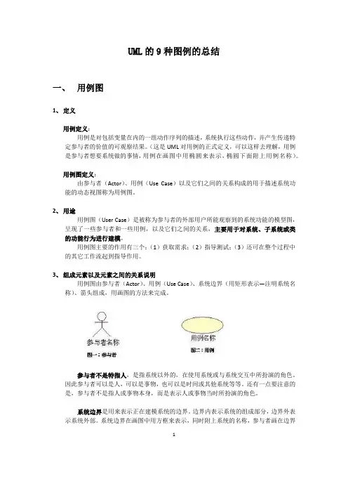
3、 组成元素以及元素之间的关系说明用例图由参与者(Actor )、用例(Use Case )、系统边界(用矩形表示—注明系统名称)、箭头组成,用画图的方法来完成。
参与者不是特指人,是指系统以外的,在使用系统或与系统交互中所扮演的角色。
因此参与者可以是人,可以是事物,也可以是时间或其他系统等等。
还有一点要注意的是,参与者不是指人或事物本身,而是表示人或事物当时所扮演的角色。
系统边界是用来表示正在建模系统的边界。
边界内表示系统的组成部分,边界外表示系统外部。
系统边界在画图中用方框来表示,同时附上系统的名称,参与者画在边界的外面,用例画在边界里面。
因为系统边界的作用有时候不是很明显,所以我个人理解,在画图时可省略。
箭头用来表示参与者和系统通过相互发送信号或消息进行交互的关联关系。
箭头尾部用来表示启动交互的一方,箭头头部用来表示被启动的一方,其中用例总是要由参与者来启动。
元素之间的关系:用例图中包含的元素除了系统边界、角色和用例,另外就是关系。
关系包括用例之间的关系,角色之间的关系,用例和角色之间的关系。
角色之间的关系:角色之间的关系。

UML中各种图的画法(全)UML中各种图的画法(全)一、UML中基本的图范畴:在 UML 2 中有二种基本的图范畴:结构图和行为图。
每个 UML 图都属于这二个图范畴。
结构图的目的是显示建模系统的静态结构。
它们包括类,组件和(或)对象图。
另一方面,行为图显示系统中的对象的动态行为,包括如对象的方法,协作和活动之类的内容。
行为图的实例是活动图,用例图和序列图。
二、UML中的类图:1.类图的表示:类的 UML 表示是一个长方形,垂直地分为三个区,如图 1 所示。
顶部区域显示类的名字。
中间的区域列出类的属性。
底部的区域列出类的操作。
在一个类图上画一个类元素时,你必须要有顶端的区域,下面的二个区域是可选择的(当图描述仅仅用于显示分类器间关系的高层细节时,下面的两个区域是不必要的)。
描述:顶部区域显示类的名字。
中间的区域列出类的属性。
底部的区域列出类的操作。
当在一个类图上画一个类元素时,你必须要有顶端的区域,下面的二个区域是可选择的(当图描述仅仅用于显示分类器间关系的高层细节时,下面的两个区域是不必要的)。
·类名:如果是抽象类,则采用斜体·类属性列表:name : attribute type 如 flightNumber : Integer,这是最常见的表达形式n ame : attribute type = default value 如balance : Dollars = 0,这是带有默认值的表达形式·类方法列表:name(parameter list) : type of value returned注意:在业务类图中,属性类型通常与单位相符,这对于图的可能读者是有意义的(例如,分钟,美元,等等)。
然而,用于生成代码的类图,要求类的属性类型必须限制在由程序语言提供的类型之中,或包含于在系统中实现的、模型的类型之中。
2.继承的表示:为了在一个类图上建模继承,从子类(要继承行为的类)拉出一条闭合的,单键头(或三角形)的实线指向超类。
UML中的用例图绘制指南及注意事项引言:UML(Unified Modeling Language)是一种用于软件系统建模的标准化语言,它提供了一套丰富的图形符号和规范,用于描述系统的结构、行为和交互。
其中,用例图是UML中最常用的图之一,用于描述系统的功能需求和用户与系统之间的交互。
本文将为读者介绍UML用例图的绘制指南及注意事项,帮助读者更好地理解和运用这一工具。
一、用例图概述用例图是用例驱动开发方法的核心,它能够帮助开发人员和用户之间更好地沟通和理解需求。
用例图主要由参与者(Actor)、用例(Use Case)和关系(Relationship)三个要素组成。
参与者指的是系统的外部用户或外部系统,用例则表示系统的功能需求,关系则描述参与者和用例之间的交互关系。
二、绘制用例图的步骤1. 确定参与者:首先需要明确系统的各个参与者,包括用户和外部系统。
参与者应该是与系统有直接交互的实体,例如管理员、用户等。
2. 识别用例:根据系统需求,识别出系统的各个功能需求,每个功能需求可以看作是一个用例。
用例应该能够描述系统的一个具体功能或者一个用户场景。
3. 绘制参与者和用例:在绘制用例图时,首先绘制参与者,然后绘制用例,用椭圆形表示。
参与者和用例之间可以用直线连接。
4. 添加关系:根据实际情况,添加参与者和用例之间的关系,常见的关系有关联(Association)、包含(Include)和扩展(Extend)等。
5. 完善用例图:根据需要,可以添加用例的详细描述、前置条件和后置条件等信息,以便更好地理解和使用用例图。
三、用例图绘制的注意事项1. 简洁明了:用例图应该尽量简洁明了,避免过多的细节和冗余信息。
只保留关键的参与者、用例和关系,以便更好地传达系统的功能需求。
2. 层次清晰:用例图应该有良好的层次结构,将不同的用例和参与者分组显示,以便更好地组织和理解系统的功能模块。
3. 一致性:用例图应该与系统的需求文档和其他模型保持一致,避免出现冲突和矛盾。
eclipse下⽣成Java类图和时序图,⽣成UML图1.安装和使⽤AmaterasUML⽤法:在⼯程名称右键选择New-Other,弹出新建对话框可以看到AmaterasUML选项,在其中选择Class Diagram,并命名后得到.cld⽂件,接着我们把⼯程network包中三个java⽂件拖拽到.cld⽂件视图中,AmaterasUML瞬间帮我们⽣成了这三个类的关系图2.安装和使⽤ModelSpoon功能:能将Eclipse中现有的java类⽣成类图⼀:什么是ModelGoon?它是⼀个Eclipse插件,⽤于基于UML图的模型设计,以及逆向⼯程(即从已有源代码⽣成类图)。
⼆:安装下载ModelGoon-4.4.1-site.zip到电脑,从eclipse中选择help-->install new software.在work with-->Add选择已经下载的ModelGoon-4.4.1-site.zip,⼀路next完成安装。
三:使⽤安装成功后,在eclipse中File-->new-->other-->ModelGoon Diagrams选择Class Diagram,在⾃⼰Java⼯程中创建⼀个后缀是.mgc的⽂件,⽤它来⽣成类图。
⽤法很简单,直接把Java类拖拽到这个⽂件视图中,就会⾃动⽣成UML类图。
2.重启Eclipse3.新建UML图:File->New->Green UML Class Diagram->输⼊UML图名->OK->⾃⼰所需的类右键->Green UML->Add to last viewed diagramPlantUML —— 应⽤于 Eclipse 的简单快速的 UML 编辑软件在应⽤系统软件开发过程中,如果软件由很多对象组成,它的结构仅仅凭借分析很难理清,同时为了有利于软件的开发及重⽤,所以在开发系统之前建模是⾮常有必要的,在众多的建模⽅法中选择⼀种适应⾃⾝应⽤特点,⽅便不同背景的⼈们交流的建模⽅法已经成为开发⼈员及⽤户的迫切愿望。
uml designer eclipse使用方法**UML Designer Eclipse 使用指南**统一建模语言(UML)是面向对象设计中的一种标准图形建模语言。
Eclipse 是一款流行的集成开发环境(IDE),它支持通过插件扩展功能,其中包括UML Designer。
UML Designer 是一个强大的工具,允许开发者在Eclipse 环境中创建和操作UML 图表。
以下是如何在Eclipse 中使用UML Designer 的详细指南。
### 安装UML Designer 插件1.打开Eclipse。
2.转到"Help" 菜单,选择"Install New Software..."。
3.在出现的对话框中,输入UML Designer 的更新站点地址。
4.选择要安装的UML Designer 插件。
5.遵循屏幕上的指示完成安装过程。
### 创建UML 图表1.在Eclipse 项目浏览器中,右击您的项目名称,选择"New"。
2.在"New" 菜单中选择"Other..."。
3.展开"UML" 文件夹,选择要创建的UML 图表类型,如"Class Diagram"。
4.填写图表名称,并选择合适的文件夹位置。
5.点击"Finish",一个新的UML 图表将被创建。
### 操作UML 元素1.在创建的UML 图表中,您可以通过右击图表空白处,选择"New" 来添加新的UML 元素。
2.可以添加类、接口、关联、依赖、继承等元素。
3.双击元素或使用属性视图可以编辑元素的属性。
4.拖放操作可以用于快速修改元素之间的关系。
### 导入和导出UML Designer 允许导入和导出不同格式的文件:- **导入**:右击图表,选择"Import",然后选择要导入的文件格式。
软件工程的23种设计模式的UML类图0 引言谈到设计模式,绝对应该一起来说说重构。
重构给我们带来了什么?除了作为对遗留代码的改进的方法,另一大意义在于,能够让我们在写程序的时候能够不需事先考虑太多的代码组织问题,当然这其中也包含了应用模式的问题。
尽管大多数开发者都已经养成了写代码前先从设计开始的习惯,但是,这种程度的设计,涉及到到大局、到总体架构、到要紧的模块划分我觉得就够了。
换句话说,这时就能写代码了。
这就得益于重构的思想了。
假如没有重构的思想,有希望获得非常高质量的代码,我们就不得不在开始写代码前考虑更多事实上并非非常稳固的代码组织及设计模式的应用问题,那开发效率当然就大打折扣了。
在重构与设计模式的合理应用之下,我们能够相对较早的开始写代码,并在功能尽早实现的同时,不断地通过重构与模式来改善我们的代码质量。
因此,下面的章节中,在谈模式的同时,我也会谈谈关于常用的这些模式的重构成本的懂得。
重构成本越高意味着,在遇到类似的问题情形的时候,我们更应该提早考虑应用对应的设计模式,而重构成本比较低则说明,类似的情形下,完全能够先怎么方便,怎么快怎么写,哪怕代码不是很优雅也没关系,回头再重构也很容易。
1 创建型1.1FactoryMethod思想:Factory Method的要紧思想是使一个类的实例化延迟到其子类。
场景:典型的应用场景如:在某个系统开发的较早阶段,有某些类的实例化过程,实例化方式可能还不是很确定,或者者实际实例化的对象(可能是需要对象的某个子类中的一个)不确定,或者者比较容易变化。
如今,假如直接将实例化过程写在某个函数中,那么通常就是if-else或者select-case代码。
假如,候选项的数目较少、类型基本确定,那么这样的if-else还是能够同意的,一旦情形变得复杂、不确定性增加,更甚至包含这个构造过程的函数所在的类包含几个甚至更多类似的函数时,这样的if-else代码就会变得比较不那么容易保护了。
1.1跟我学UML建模工具StarUML(第4部分)——应用StarUML创建类图的创建示例1.1.1UML类图1、UML类图(1)类图类是面向对象模型的最基本的模型元素。
类图表达为了实现某一用例中的一组对象类之间的静态结构,以及它们之间的联系和交互。
(2)类图的作用主要体现在描述结构和联系:类图描述系统中类的静态结构,它不仅定义系统中的类,表示类之间的联系(关联、依赖、聚合等),还包括类的内部结构(类的属性和操作)。
(3)类的UML的图示类是对象的集合,这些对象有共同的结构特征、行为特征、联系和语义;在UML中类的图形表示为实线矩形框。
但要注意的是:在类图中不一定要列出全部的成员内容。
如在建立分析模型或设计模型时,可以只列出类名,在图中只需要着重表达类之间的联系;在建立实现模型时,再在类图中给出类的组成成员属性和操作方法等方面的详细内容。
如下图所示:2、类中的属性成员及其UML的图示(1)属性(成员变量)类中的成员属性表示的形式为:可视性属性名(多重性):类型=初始值其中的可视性可以为:公共、保护和私有三种不同的形式,而类型也就是数据类型,依赖于所选择的编程实现的语言。
(2)类的static成员属性所应该注意的是,对类的成员属性也就是static成员属性在类图中的表示为带下划线的形式。
如下面的Compute类中的“oneUSBDevice”成员属性的表示方式。
3、类中的方法成员及其UML的图示(1)类中的操作(成员方法)操作是类的行为特征或动态特征,用于对服务或实体相关的操作建模。
一个类可以有操作并且可以允许有多个不同的操作,当然也可以没有。
没有一个功能操作方法的类经常用于表达数据。
功能操作方法在类图中位于最底部,同时用文字串说明。
其表示为:可视性操作名(参数列表):返回列表{性质}(2)类中的操作的类型1)实现者操作(Implementor operations):实现一些业务功能。
实现者操作可从交互图中找到。
使⽤IDEA画UML图的详细步骤⽬录UML简介如何使⽤IDEA画UML图安装PlantUML插件安装GraphvizGraphviz安装和环境变量配置Graphviz安装环境变量配置UML简介 统⼀建模语⾔ (Unified Modeling Language,UML) 是⼀种为⾯向对象系统的产品进⾏说明、可视化和编制⽂档的⼀种标准语⾔,是⾮专利的第三代建模和规约语⾔。
UML是⾯向对象设计的建模⼯具,独⽴于任何具体程序设计语⾔。
1 UML 作为⼀种统⼀的软件建模语⾔具有⼴泛的建模能⼒。
UML 是在消化、吸收、提炼⾄今存在的所有软件建模语⾔的基础上提出的,集百家之所长,它是软件建模语⾔的集⼤成者。
UML还突破了软件的限制,⼴泛吸收了其他领域的建模⽅法,并根据建模的⼀般原理,结合了软件的特点,因此具有坚实的理论基础和⼴泛性。
UML不仅可以⽤于软件建模,还可以⽤于其他领域的建模⼯作。
1 UML ⽴⾜于对事物的实体、性质、关系、结构、状态和动态变化过程的全程描述和反映。
UML可以从不同⾓度描述⼈们所观察到的软件视图,也可以描述在不同开发阶段中的软件的形态。
UML可以建⽴需求模型、逻辑模型、设计模型和实现模型等,但UML在建⽴领域模型⽅⾯存在不⾜,需要进⾏补充。
1 作为⼀种建模语⾔,UML有严格的语法和语义规范。
UML建⽴在元模型理论基础上,包括 4 层元模型结构,分别是基元模型、元模型、模型和⽤户对象。
4 层结构层层抽象,下⼀层是上⼀层的实例。
UML中的所有概念和要素均有严格的语义规范。
1 UML 采⽤⼀组图形符号来描述软件模型,这些图形符号具有简单、直观和规范的特点,开发⼈员学习和掌握起来⽐较简单。
所描述的软件模型,可以直观地理解和阅读,由于具有规范性,所以能够保证模型的准确、⼀致。
1如何使⽤IDEA画UML图安装PlantUML插件 使⽤ IDEA 画 UML 图需要安装 plantMUL 插件。
PlantUML 是⼀个⽀持快速绘制的开源项⽬。
MDT/UML2/Getting Started with UML2 < MDT| UML2Copyright © 2004, 2014 International Business Machines Corp., CEA, and others.Contents[hide]1 Summary2 Prerequisites3 Introduction4 Getting Started5 Creating Models6 Creating Packages7 Creating Primitive Types8 Creating Enumerations9 Creating EnumerationLiterals10 Creating Classes11 Creating Generalizations12 Creating Attributes13 Creating Associations14 Saving Models15 Conclusion16 ReferencesSummaryThis article describes how to get started with the UML2 plug-ins for Eclipse. In particular, it gives an overview of how to create models (and their contents) both programmatically and by using the sample UML editor.Kenn Hussey and James BruckLast Updated: January 21, 2014PrerequisitesTo start using UML2 (and to follow along with the example in this article), you must have Eclipse, EMF, and UML2 installed. You caneither download the Modeling Tools Package or follow these steps: 1Download and run Eclipse.2Select the Help > Install New Software… menu item.3Select a software site to work with, e.g., Luna -/releases/luna.4Expand the Modeling tree item.5Select UML2 Extender SDK and press the Next > button.6Review the install details and press the Next > button.7Accept the terms of the license agreement and press the Finish button.8Restart Eclipse when prompted to do so.At this stage, UML2 and all dependencies should be installed. IntroductionThis article will walk you through the basics of creating models using UML2. Using a simple model (the ExtendedPO2 model, shamelessly “borrowed” from the EMF “bible” [1]) as an example, we’ll lookat what’s involved in creating some of the more common elements that make up a model. For each type of element, we’ll first explain the creation process using the sample UML editor and then explore how to accomplish the same thing using Java code. The ExtendedPO2 model is shown below.Getting StartedReaders who don't want to follow every step of this tutorialmay install a working solution from the New → Example... wizard, selecting the UML2 Example Projects → Getting Started with UML2 sample. This will be available when Enhancement 382342 is resolved and released in a UML2 build. This includes the finished model, complete source code, and a launch configuration that runs the stand-alone Java application which creates the model in the root folder of the example project.Before getting started, you’ll need to create a simple project in your workspace. This project will serve as the container for the model that we’ll create using the UML editor. To create a simple project for this article, follow these steps:9Select the Window > Open Perspective > Other… menu item.10 Select the Resource perspective and press the OK button.11 Select the File > New > Project... menu item.12 Select the Project wizard from the General category and pressthe Next > button.13 Enter a project name (e.g. “Getting Started with UML2”) andpress the Finish button.At this point your workspace should look something like this:OK, that should be enough to get us going with the UML editor. Now, to follow along with the programmatic approach to creating models, we’ll assume that you’ve created a class (named, say,“GettingStartedWithUML2”) in which you can write some code to construct our sample model. The code snippets we’ll show assume you’ve defined the following utility methods to give the user information on the program’s status:public static boolean DEBUG = true;protected static void out(String format, Object... args) {if (DEBUG) {System.out.printf(format, args);if (!format.endsWith("%n")) {System.out.println();}}}protected static void err(String format, Object... args) {System.err.printf(format, args);if (!format.endsWith("%n")) {System.err.println();}}A static debug flag can be used to enable or disable verboseinformation printed to the system’s output stream. Errors will always be printed to the system’s error stream.All right, then! In each of the following subsections, we’ll look at how to create a different kind of UML element, starting with models. Creating ModelsAt the root of a typical UML model is a model element. It contains a (hierarchical) set of elements that together describe the physical system being modeled. To create a model using the UML editor, follow these steps:14 Select a project (e.g., Getting Started with UML2) in theProject Explorer view and select the File > New > Other... menu item.15 Select the UML Model wizard from the Example EMF ModelCreation Wizards category and press the Next > button.16 Enter a file name (e.g., “ExtendedPO2.uml”) and press theNext > button.17 Select Model for the model object and press the Finish button.18 Select the Window > Show View > Properties menu item.19 Select the <Model> element in the UML editor.20 Enter a value (e.g., “epo2”) for the Name property in theProperties view.At this point your workspace should look something like this:Let’s look at how to perform the same task using Java code. The code snippet below shows a method that programmatically creates and returns a model with a specified name.protected static Model createModel(String name) {Model model = UMLFactory.eINSTANCE.createModel();model.setName(name);out("Model '%s' created.", model.getQualifiedName());return model;}First, we ask the UML factory singleton to create a model, and we set its name. Then, we output information to let the user know that the model has been successfully created. Finally, we return the model. You’ll notice most, if not all, of the code snippets in this article willfollow this pattern – create the element (and set some properties on it), inform the user, and return it.All named elements (a model is a type of named element)have a “simple” name and a qualified name. The qualified name isthe “simple” name prefixed with the “simple” names of all of thenamed element’s containing namespaces. Note that the qualified name of a named element is only defined if all of its containing namespaces have non-empty “simple” names.OK, let’s see this method in action. For example, we could create a model named ‘epo2’ as follows:Model epo2Model = createModel("epo2");Creating PackagesA package is a namespace for its members (packageable elements), and may contain other packages. A package can import either individual members of other packages, or all of the members of other packages. To create a package using the UML editor, follow these steps:21 Select a package (e.g., <Package> epo2) in the UML editor.22 Select the New Child > Nested Package > Package optionfrom the context menu.23 Enter a value (e.g., “bar”) for the Name property in theProperties view.We don’t actually need to create a package because our sample model doesn’t contain any &emdash; except of course for the root package (i.e., the model). That’s right: a model is a type of package.Let’s look at how to perform the same task using Java code. The code snippet below shows a method that programmatically creates and returns a package with a specified name in a specified nesting package.protected static org.eclipse.uml2.uml.PackagecreatePackage(org.eclipse.uml2.uml.Package nestingPackage, String name) {org.eclipse.uml2.uml.Package package_ = nestingPackage.createNestedPackage(name);out("Package '%s' created.", package_.getQualifiedName());return package_;}Here, instead of asking the factory to create the package for us, we’re making use of one of the factory methods in the UML2 API. In UML2, a factory method exists for every feature that can contain other elements (i.e., every containment feature). In addition, more convenient factory methods exist for commonly created types (like packages). In this case, the package has a feature (packagedElement) that can contain packageable elements, so we could obtain the Ecore class of the type of (packageable) element we want to create (i.e., Package) from the UML Ecore package singleton, and pass it to the createPackagedElement(String, EClass) factory method. Instead, we use the moreconvenient createNestedPackage(String) factory method which implicitly creates a package and accepts the desired package name as an argument. Behind the scenes, the package will create a nested package, set its name, and add the package to its list of packaged elements.OK, let’s see this method in action. For example, we could create a package named ‘bar’ in nesting package ‘foo’ as follows:org.eclipse.uml2.uml.Package barPackage =createPackage(fooPackage, "bar");Creating Primitive TypesA primitive type defines a predefined data type, without any relevant substructure. Primitive types used in UML™ itself include Boolean, Integer,Real, String, and UnlimitedNatural. To create a primitive type using the UML editor, follow these steps:24 Select a package (e.g., <Model> epo2) in the UML editor.25 Select the New Child > Owned Type > Primitive Type optionfrom the context menu.Enter a value (e.g., “int”) for the Name property in theProperties view.Create the remaining primitive types from the ExtendedPO2model using the UML editor.At this point your workspace should look something like this:Let’s look at how to perform the same task using Java code. The code snippet below shows a method that programmatically creates and returns a primitive type with a specified name in a specified package.protected static PrimitiveTypecreatePrimitiveType(org.eclipse.uml2.uml.Package package_, String name) {PrimitiveType primitiveType =package_.createOwnedPrimitiveType(name);out("Primitive type '%s' created.",primitiveType.getQualifiedName());return primitiveType;}Here we call the createOwnedPrimitiveType(String) convenience factory method to ask the package to create a primitive type with the specified name as one of its packaged elements.OK, let’s see this method in action. For example, we could create a primitive type named ‘int’ in model ‘epo2’ as follows: PrimitiveType intPrimitiveType = createPrimitiveType(epo2Model, "int");Write code to programmatically create the remainingprimitive types from the ExtendedPO2 model.Creating EnumerationsAn enumeration is a kind of data type whose instances may be any of a number of user-defined enumeration literals. To create an enumeration using the UML editor, follow these steps:Select a package (e.g., <Model> epo2) in the UML editor.28 Select the New Child > Owned Type > Enumeration optionfrom the context menu.29 Enter a value (e.g., “OrderStatus”) for the Name property inthe Properties view.At this point your workspace should look something like this:Let’s look at how to perform the same task using Java code. The code snippet below shows a method that programmatically creates and returns an enumeration with a specified name in a specified package.protected static EnumerationcreateEnumeration(org.eclipse.uml2.uml.Package package_, String name) {Enumeration enumeration =package_.createOwnedEnumeration(name);out("Enumeration '%s' created.",enumeration.getQualifiedName());return enumeration;}Here we call the createOwnedEnumeration(String) convenience factory method to ask the package to create a primitive type with the specified name as one of its packaged elements.OK, let’s see this method in action. For example, we could create an enumeration named ‘OrderStatus’ in model ‘epo2’ as follows: Enumeration orderStatusEnumeration =createEnumeration(epo2Model, "OrderStatus");Creating Enumeration LiteralsAn enumeration literal is a user-defined data value for an enumeration. To create an enumeration literal using the UML editor, follow these steps:30 Select an enumeration (e.g., <Enumeration> OrderStatus) inthe UML editor.31 Select the New Child > Owned Literal > Enumeration Literaloption from the context menu.Enter a value (e.g., “Pending”) for the Name property in the Properties view.Create the remaining enumeration literals from theExtendedPO2 model using the UML editor.At this point your workspace should look something like this:Let’s look at how to perform the same task using Java code. The code snippet below shows a method that programmatically creates and returns an enumeration literal with a specified name in a specified enumeration.protected static EnumerationLiteralcreateEnumerationLiteral(Enumeration enumeration, String name) { EnumerationLiteral enumerationLiteral =enumeration.createOwnedLiteral(name);out("Enumeration literal '%s' created.", enumerationLiteral.getQualifiedName());return enumerationLiteral;}Here we call a createOwnedLiteral(String) convenience factory method to ask the enumeration to create an enumeration literal with the specified name as one of its owned literals.OK, let’s see this method in action. For example, we could create an enumeration literal named ‘Pending’ in enumeration‘OrderStatus’ as follows:createEnumerationLiteral(orderStatusEnumeration, "Pending");Write code to programmatically create the remainingenumeration literals from the ExtendedPO2 model.Creating ClassesA class is a kind of classifier whose features are attributes (some of which may represent the navigable ends of associations) and operations. To create a class using the UML editor, follow these steps: Select a package (e.g., <Model> epo2) in the UML editor.34 Select the New Child > Owned Type > Class option from thecontext menu.35 Enter a value (e.g., “Supplier”) for the Name property in theProperties view.Create the remaining classes from the ExtendedPO2 modelusing the UML editor.At this point your workspace should look something like this:Let’s look at how to perform the same task using Java code. The code snippet below shows a method that programmatically creates and returns a(n) (abstract) class with a specified name in a specified package.protected static org.eclipse.uml2.uml.ClasscreateClass(org.eclipse.uml2.uml.Package package_, String name, boolean isAbstract) {org.eclipse.uml2.uml.Class class_ =package_.createOwnedClass(name, isAbstract);out("Class '%s' created.", class_.getQualifiedName());return class_;}Here we call the createOwnedClass(String, boolean) convenience factory method to ask the package to create a class with the specified name as one of its packaged elements, and set the isAbstract attribute of the class based on the specified boolean argument.You may have noticed that we have been fully qualifyingreferences to the Package and Class interfaces. This is recommended so that these types are not confused withng.Class and ng.Package, which are imported implicitly in Java.OK, let’s see this method in action. For example, we could create a non-abstract class named ‘Supplier’ in model ‘epo2’ as follows: org.eclipse.uml2.uml.Class supplierClass =createClass(epo2Model, "Supplier", false);Write code to programmatically create the remaining classesfrom the ExtendedPO2 model.Creating GeneralizationsA generalization is a taxonomic relationship between a specificclassifier and a more general classifier whereby each instance of the specific classifier is also an indirect instance of, and inherits the features of, the general classifier. To create a generalization using the UML editor, follow these steps:36 Select a classifier (e.g., <Class> USAddress) in the UMLeditor.37 Select the New Child > Generalization > Generalizationoption from the context menu.38 Select a value (e.g., epo2::Address) for the General propertyin the Properties view.Create the remaining generalizations from the ExtendedPO2model using the UML editor.At this point your workspace should look something like this:Let’s look at how to perform the same task using Java code. The code snippet below shows a method that programmatically creates and returns a generalization between specified specific and general classifiers.protected static Generalization createGeneralization(Classifier specificClassifier, Classifier generalClassifier) {Generalization generalization =specificClassifier.createGeneralization(generalClassifier);out("Generalization %s --|> %s created.", specificClassifier.getQualifiedName(),generalClassifier.getQualifiedName());return generalization;}Here we call a convenience factory method on the specific classifier that creates a generalization as one of its children and sets the general classifier to the specified argument.OK, let’s see this method in action. For example, we could create a generalization between specific class ‘USAddress’ and general class ‘Address’ as follows:createGeneralization(usAddressClass, addressClass);Write code to programmatically create the remaininggeneralizations from the ExtendedPO2 model.Creating AttributesWhen a property is owned by a classifier it represents an attribute; in this case is relates an instance of the classifier to a value or set of values of the type of the attribute.The types of Classifier that can own attributes in UML2include Artifact, DataType, Interface, Signal, andStructuredClassifier (and their subtypes).To create an attribute using the UML editor, follow these steps:39 Select a classifier (e.g., <Class> Address) in the UML editor.40 Select the New Child > Owned Attribute > Property optionfrom the context menu.41 Enter a value (e.g., "name”) for the Name property in theProperties view.42 Select a value (e.g., epo2::String) for the Type property in theProperties view.43 Enter a value (e.g., 0) for the Lower property in the Propertiesview.Lower and upper values for multiplicity elements (likeproperties) are represented as value specifications (first-class objects)in UML™ 2.x. The default value for lower and upper bounds is 1,unless a child value specification exists, in which case its value is used. Specifying a value for the lower or upper property will create a child value specification if none exists, or update its value if one does. Note that, to be treated as a bound, the lower value must be an integer and the upper value must be an unlimited natural.Create the remaining attributes from the ExtendedPO2model using the UML editor.At this point your workspace should look something like this:Let’s look at how to perform the same task using Java code. The code snippet below shows a method that programmatically creates and returns an attribute with a specified upper bound, lower bound, type, and name in a specified class.protected static PropertycreateAttribute(org.eclipse.uml2.uml.Class class_, String name, Type type, int lowerBound, int upperBound) {Property attribute = class_.createOwnedAttribute(name, type, lowerBound, upperBound);out("Attribute '%s' : %s [%s..%s] created.", //attribute.getQualifiedName(), // attribute nametype.getQualifiedName(), // type namelowerBound, // no special case for multiplicity lower bound(upperBound == LiteralUnlimitedNatural.UNLIMITED)? "*" // special case for unlimited bound: upperBound);return attribute;}Here we call a createOwnedAttribute(String, Type, int, int) convenience factory method to ask the class to create a property as one of its owned attributes, set the type of the attribute to the specified type, and set the lower and upper bounds of the attribute (the factory method indirectly creates a literal integer and literal unlimited natural, respectively, and sets their values to the specified integer values).The LiteralUnlimitedNatural.UNLIMITED constantrepresents the unlimited value for upper bounds (-1), as it does in EMF; when setting this value in the Properties view, an asterisk(‘*’) can alternatively be specified.OK, let’s see this method in action. For example, we could create anattribute with multiplicity 0..1 of type ‘String’ named ‘name’ in class ‘Supplier’ as follows:createAttribute(supplierClass, "name", stringPrimitiveType, 0, 1);Write code to programmatically create the remainingattributes from the ExtendedPO2 model.Creating AssociationsAn association specifies a semantic relationship that can occur between two or more typed instances; its ends are represented by properties, each of which is connected to the type of the end. When a property is owned by an association it represents a non-navigable end of the association, in which case the type of the property is the type of the association end.The notion of association end navigability was separatedfrom that of ownership in the UML™ 2.0 specification, so a property that is owned by an association isn’t necessarily non-navigable as of UML2 2.0.To create an association using the UML editor, follow these steps:44 Select a package (e.g., <Model> epo2) in the UML editor.45 Select the New Child > Owned Type > Association optionfrom the context menu.46 Enter a value (e.g., “A_orders_supplier”) for the Nameproperty in the Properties view.47 Select the association (e.g., <Association>A_orders_supplier) in the UML editor.48 Select the New Child > Owned End > Property option fromthe context menu.49 Select a value (e.g., epo2::Supplier) for the Type property inthe Properties view.50 Select a class (e.g., <Class> Supplier) in the UML editor.51 Select the New Child > Owned Attribute > Property optionfrom the context menu.52 Select a value (e.g., Composite) for the Aggregation propertyin the Properties view.53 Select a value (e.g., epo2::A_orders_supplier) for theAssociation property in the Properties view.54 Enter a value (e.g., "orders") for the Name property in theProperties view.55 Select a value (e.g., epo2::PurchaseOrder) for the Typeproperty in the Properties view.56 Enter a value (e.g., 0) for the Lower property in the Propertiesview.57 Enter a value (e.g., *) for the Upper property in the Propertiesview.Create the remaining associations from the ExtendedPO2model using the UML editor.At this point your workspace should look something like this:Let’s look at how to perform the same task using Java code. The code snippet below shows a method that programmatically creates and returns an association between two specified types, with ends that have the specified upper bounds, lower bounds, role names,aggregation kinds, and navigabilities.protected static Association createAssociation(Type type1, boolean end1IsNavigable, AggregationKind end1Aggregation, String end1Name, int end1LowerBound, int end1UpperBound,Type type2, boolean end2IsNavigable, AggregationKind end2Aggregation, String end2Name, int end2LowerBound, intend2UpperBound) {Association association =type1.createAssociation(end1IsNavigable, end1Aggregation,end1Name, end1LowerBound, end1UpperBound,type2, end2IsNavigable, end2Aggregation, end2Name, end2LowerBound, end2UpperBound);out("Association %s [%s..%s] %s-%s %s [%s..%s] created.", //UML2Util.isEmpty(end1Name)// compute a placeholder for the name? String.format("{%s}", type1.getQualifiedName()) //// user-specified name: String.format("'%s::%s'",type1.getQualifiedName(), end1Name), //end1LowerBound, // no special case for this(end1UpperBound ==LiteralUnlimitedNatural.UNLIMITED)? "*" // special case for unlimited upper bound: end1UpperBound, // finite upper boundend2IsNavigable? "<" // indicate navigability: "-", // not navigableend1IsNavigable? ">" // indicate navigability: "-", // not navigableUML2Util.isEmpty(end2Name)// compute a placeholder for the name? String.format("{%s}", type2.getQualifiedName()) //// user-specified name: String.format("'%s::%s'",type2.getQualifiedName(), end2Name), //end2LowerBound, // no special case for this(end2UpperBound ==LiteralUnlimitedNatural.UNLIMITED)? "*" // special case for unlimited upper bound: end2UpperBound);return association;}Here we call a convenience factory method on the first end type that creates an association (and its ends) between it and another type as one of its siblings (i.e. as a child of its package namespace) and with the specified upper bounds, lower bounds, role names, aggregation kinds, and navigabilities. The owners of the association ends (properties) are based on the specified navigabilities – navigable ends are owned by the end type if allowed, otherwise they are ownedby the association; non-navigable ends are owned by the association.The NamedElement.SEPARATOR constant represents thestandard separator (::) used in qualified names.OK, let’s see this method in action. For example, we could create a unidirectional composition (composite association) between classes ‘Supplier’ and ‘PurchaseOrder’ in model ‘epo2’ as follows:createAssociation(supplierClass, true,POSITE_LITERAL, "orders", 0, LiteralUnlimitedNatural.UNLIMITED,purchaseOrderClass, false,AggregationKind.NONE_LITERAL, "", 1, 1);Write code to programmatically create the remainingassociations from the ExtendedPO2 model.Saving ModelsNow that we’ve spent all this time creating a model, we’d better save our work. When we created our model using the UML model wizard, a UML resource was created for us, so now all that needs to be done is to serialize the contents of our model as XMI to our file on disk (i.e.,ExtendedPO2.uml). To save a model using the UML editor, follow these steps:Select the File > Save menu item.It’s that simple. Programmatically, we have a bit more work to do because so far, we’ve been creating our model in a vacuum, i.e. without a containing resource. The code snippet below shows a method that saves a specified package to a resource with a specified URI.protected static void save(org.eclipse.uml2.uml.Package package_, URI uri) {// Create a resource-set to contain the resource(s) that we are savingResourceSet resourceSet = new ResourceSetImpl();// Initialize registrations of resource factories, library models,// profiles, Ecore metadata, and other dependencies required for// serializing and working with UML resources. This is only necessary in// applications that are not hosted in the Eclipse platformrun-time, in// which case these registrations are discovered automatically from// Eclipse extension points.UMLResourcesUtil.init(resourceSet);// Create the output resource and add our model package to it.Resource resource = resourceSet.createResource(uri);resource.getContents().add(package_);// And savetry {resource.save(null); // no save options neededout("Done.");} catch (IOException ioe) {。