ROSEMOUNT 3051变送器HART375树形菜单中英文对照
- 格式:xlsx
- 大小:13.09 KB
- 文档页数:6


使用手册00809-0100-4001,版本 EA 采用HART协议的3051型压力变送器3051 型使用手册00809-0100-4001,版本 EA 3051 型3051 型压力变送器注意在使用产品前务必阅读本手册。
为了确保人身安全和系统安全并使产品达到最佳性能,在产品安装、使用或维修前必须确保已完全理解本手册中的内容。
如此中文版本使用手册个别内容与英文版本描述不同,请以英文版本为准。
免费客户服务热线:800-820-1996 联系当地的罗斯蒙特销售办事处,请拨打:北京 010-********上海 021-********广州 020-********西安 029-********乌鲁木齐 0991-*******警告本手册描述产品的设计用途不包括核级资质应用领域。
将非核级资质产品用于需要核级资质硬件或产品的应用领域会产生错误的读数。
如需罗斯蒙特核级资质产品,请联系当地罗斯蒙特销售代表。
罗斯蒙特 3051 型智能压力变送器受下列一种或多种专利保护:美国专利证书号:4466290;4612812; 4791352; 4798089; 4818994; 4866435;4878012;4988990; 4926340; 5083091; 5122794; 5166678; 5248167;5278543; 5287746; 5329818;5333504; 5585777; 6017143; 6119047;6295875; Des. 317266; Des. 318432; Des 342456。
具体情况取决于相关型号。
其他颁发的及等待颁发的美国和外国专利。
艾默生过程控制有限公司履行所有法律义务以满足欧盟产品要求。
3051 型使用手册00809-0100-4001,版本 EA 3051 型目录第一章简介如何使用手册 . . . . . . . . . . . . . . . . . . . . . . . . . . . . . . . . . . . . . . . .服务支持 . . . . . . . . . . . . . . . . . . . . . . . . . . . . . . . . . . . . . . .包括型号. . . . . . . . . . . . . . . . . . . . . . . . . . . . . . . . . . . . . . . . . . . .变送器概述. . . . . . . . . . . . . . . . . . . . . . . . . . . . . . . . . . . . . . . . . .1-11-11-21-3第二章安装概述 . . . . . . . . . . . . . . . . . . . . . . . . . . . . . . . . . . . . . . . . . . . . . . .安全信息 . . . . . . . . . . . . . . . . . . . . . . . . . . . . . . . . . . . . . . . .. . . .警告 . . . . . . . . . . . . . . . .. . . . . . . . . . . . . . . . . . . . . . . . . .总体描述 . . . . . . . . . . . . . . . . . . . . . . . . . . . . . .. . . . . . . . . . . . .机械描述 . . . . . . . . . . . . .. . . . . . .. . . . .. . . . .. . . . . . . . . . . .量程描述 . . . . . . . . . . . .. . . .. .. . . . . . . . . . . . . . . . .. . . . . .环境描述. . . . . . . . . . . . . . . . . . . . . . . . . . . . . . . . .. . . . . . . . . .安装程序. . . . . . .. . . .. . .. . . . . . . . . . . . . . . . . . . . . . . . . . . . . . . .安装变送器. . . . . . . . . . . . ... . . . . . . . . . . . . . . . . . . . . . . . .过程连接. . . . . . . . . . . . . . . . . . . . . .. . . . . . . . . . . . . . . . . .外壳旋转描述. . . . . . . . . . . . . . . . . . . . . .. . . . . . . . . . . . . . . .设置跳线 . . . . . . . . . . . . . . . . . . . . . . . . . . . . . . . . . . . . . . . .接线并接通电源. . . . . . .. . . . . . . . . . . . .. . . . . . . . . . . . . . .危险场所. . . . . . . . . . . . . . . . . . . . . . . . . . . . . . . . . . . . . . . . . . .变送器外壳接地. . . . . . . . . . . . . . . . . . .. . . . . . . . . . . . . . . . .安装液晶显示器 . . . . . . . . . . . . . . . . . . . . . .. . . . . . . . . . . . . . .305 型和 306 型一体化阀组. . . . . . . . . . . .. . ... . . . . . . . . . . . . .安装程序. . . . . . . . . . .. . . . . . . . . . . . . . . . . . . . . . . . . . .2-12-12-12-22-32-32-42-62-62-112-132-142-162-182-182-192-222-22第三章组态概述 . . . . . . . . . . . . . . . . . . . . . . . . . . . . . . . . . . . . . . . . . . . . . . .安全信息 . . . . . . . . . . . . . . . . . . . . .. . . . . . . . . . . . . . . . . . . . . .报警 . . . .. . . . . . . . . . . . . . . . . . . . . . . . . . . . . . . . . . . . . . .试验台上用 HART 试运行. . . . . . . . . .. . . . . . . . . . . . . . . . . . . .按照手册设置回路. . . . . . . . . . . . . . . . . . . . . . . . . . . . . . . . . . .接线图. . . . . . . . . . . . . . . . . . . . . . . . . . . . . . . . . . . . . . . . . .275 型 HART 通讯装置. . . . . . . . . . . . . . . . . . . . . . . . . . . . . . . .审核组态数据. . . . . . . . . . . . . . . . . . . .. . . . . . . . . .. . . . . . . . . .检查输出. . . . . . . . . . . . . . . . . . . . . . . . . . . . . . . . . . . . . . . . . .过程变量. . . . . . . . . . . . . . . . . . . . . . . . . . . . . . . . . . . . . . . . .传感器温度. . . . . . . . . . . . . . . . . . . . . . . . . . . . . . . . . . . . . .基本设置 . . . . . . . . . . . . . . . . . . . . . . .. . . . . . . . . . . . . . . . . . . . .设置过程变量单位. . . . . . . . . . . . . . .. . .. . . . . . . . . . . . .设置输出 . . . . . . . . . . . . . .. . . . . . . . . . . . . . . . . . . . . . . . . .重置量程 . . . . . . . . . . . . . . . . . . . . . . . . . .. . . . . . . . . . . . . .阻尼 . . . . . . . . .. . . . . . . . . . . . . . . . . . . . . . . . . . . . . . . . . .3-13-13-13-23-23-33-43-73-73-73-83-83-83-93-103-163051 型液晶显示器. . . . . . . . . . . . . . . . . . . . . . . . . . . . . . . . . . . . . . . . . .标准显示组态. . . . . . . . .. . . . . . . . . . . . . . . . . . . . . . . . . .自定义显示组态. . . . . . . . . . . . . . . .. . . . . . . . . . . . . . . . . . 详细设置 . . . . . . . . . . . . . . . . . . . . . . . . . . . . . . . . . . . . . . . . . .故障模式报警和饱和电平. . . . . . . . . . . . . . . . . . . . . . . . . . .触发模式报警和饱和电平. . . . . . . . . . . . . . . . . . . . . . . . . . . .多站式模式报警和饱和值. . . . . . . . . . . . . . . . . . . . . . . . . . . .报警电平检验. . . . . . . . . . . . . . . . . . . . . . . . . . . . . . . . . . . .传感器温度单位 . . . . . . . . . . . . . .. . . . . . . . . . . . . . . . . . . . . 诊断和服务. . . . . . . . . . . . . . . . . . . . . . . . . . . . . . . . . . . . . .变送器测试 . . . . . . . . . . . . . . . . . . . . . . . . . . . . . . . . . . . . . .回路测试 . . . . . . . . . . . . . . . . . . . . . . . . . . . . . . . . . . . . . . . . 先进功能 . . . . . . . . . . . . . . . . . . . . . . . . . . . . . . . . . . . . . . . . .保存、取消和克隆组态数据 . . . . . . . . . . . . . . . . . .. . . . .触发模式 . . . . . . . . . . . .. . . . . . . . . . . . . . . . . . . . . . . . . . . . 多站式通讯 . . . . . . . . . . . . . . . . . . .. . . . . . . . . . . . . . . . . . . . . .改变变送器地址 . . . . . . . . . . . . . . . . . . . . . . . . . . . . . . . . . .与多站式变送器通讯 . . . . . . . . . . . . . . . . . . . . . .. . . . . . . . .对多站式变送器查询. . . . . . . . . . . . . . . . . . . . . 3-16 3-17 3-17 3-19 3-19 3-20 3-20 3-20 3-20 3-21 3-21 3-21 3-22 3-22 3-24 3-25 3-26 3-27 3-27第四章使用和维护概述 . . . . . . . . . . . . . . . . . . . . . . . . . . . . . . . . . . . . . . . . . . . .安全信息 . . . . . . . . . . . . . . . . . . . . . . . . . . . . . . . . . . . . . . . . .警告 . . . . . . . . . . . . . . . . . . . . . . . . . . . . . . . . . . . . . . . . . . .标定 . . . . . . . . . . . . . . . . . . . . . . . . . . . . . . . . . . . . . . . . . . . . . .标定概述 . . . . . . . . . . . . . . . . . . . . . . . . . . . . . . . . . . .确定标定频率 . . . . . . . . . . . . . . . . . . . . . . . .选择微调程序 . . . . . . . . . . . . . . . . . . . . . . . . . . . . . .传感器微调 . . . . . . . . . . . . . . . . . . . . . . . . . . . . . . . . . . . . . .零点微调 . . . . . . . . . . . . . . . . . . . . . . . . . . . . . . . . . . . . . .全量程微调 . . . . . . . . . . . . . . . . . . . . . . . . . . . . . . . . . . . . .恢复工厂微调 . . . . . . . . . . . . . . . . . . . . . . . . . . . . . . . . . . . .模拟输出微调 . . . . . . . . . . . . . . . . . . . . . . . . . . . . . . . . . . .数/模转换微调. . . . . . . . . . . . . . . . . . . . . . . . . . . . . . . . . .应用其他刻度进行数/模转换微调. . . . . . . . . . . . . . . . . .静压补偿 . . . . . . . . . . . . . . . . . . . . . . . . . . . . . . . . . . . . . .诊断信息 . . . . . . . . . . . . . . . . . . . . . . . . . . . . . . . . .本机零点及量程(本机键)软件锁定 . . . . . . . . . . . . . . . .本机零点及量程的实体拆除(本机键) . . . . . . . . . . . . .选择低功耗输出量程 . . . . . . . . . . . . . . . . . . . . . .详细设置 . . . . . . . . . . . . . . . . . . . . . . . . . . . . . . . . . . . . . . . . . .本机量程与零点控制(本机键). . . . . . . . . . . . . . . . . .4-14-14-14-24-34-44-64-64-74-84-94-104-104-114-124-144-194-194-204-204-20第五章故障检修概述 . . . . . . . . . . . . . . . . . . . . . . . . . . . . . . . . . . . . . . . . . . . . . . .安全信息 . . . . . . . . . . . . . . . . . . . . . . . . . . . . . . . . . . . . . . . . .警告 . . . . . . . . . . . . . . . . . . . . . . . . . . . . . . . . . . . . . . . . . . . .拆卸变送器之前. . . . . . . . . . . . . . . . . . . . . . . . .拆卸程序 . . . . . . . . . . . . . . . . . . . . . . . . . . . . . . . . . . .从服务地点拆除变送器 . . . . . . . . . . . . . . . . . . . . . .拆除端子块 . . . . . . . . . . . . . . . . . . . . . . . . . . . . . .拆除电子线路板 . . . . . . . . . . . . . . . . . . . . . . . . . . . .从电子元件外壳中拆除传感器模块 . . . . . .5-15-15-15-35-35-35-45-45-5目录-2使用手册00809-0100-4001,版本 EA 3051 型重新装配程序 . . . . . . . . . . . . . . . . . . . . . . . . . . . . . . . . . . .安装电子线路板 . . . . . . . . . . . . . . . . . . . . . . . . . . . . .安装端子块 . . . . . . . . . . . . . . . . . . . . . . . . . . . . . . . .重新装配过程传感器本体 . . . . . . . . . . . . . . . . . . . . . 5-5 5-6 5-6 5-7附录 A 参考信息性能说明 . . . . . . . . . . . . . . . . . . . . . . . . . . . . . . . . .详细性能说明. . . . . . . . . . . . . . . . . . . . . . . . . .参考精度 . . . . . . . . . . . . . . . . . . . . . . . . . . . . . . . . . . . .环境温度. . . . . . . . . . . . . . . . . . . . . . . . . . . . . . . . . . .静压影响 . . . . . . . . . . . . . . . . . . . . . . . . . . . . . . . . . . .动态性能 . . . . . . . . . . . . . . . . . . . . . . . . . . . . . . . . . .安装位置影响 . . . . . . . . . . . . . . . . . . . . . . . . . . . . . . . .振动影响 . . . . . . . . . . . . . . . . . . . . . . . . . . . . . . . . . . . . . . . .电源影响 . . . . . . . . . . . . . . . . . . . . . . . . . . . . . . . . . . . .射频干扰影响 . . . . . . . . . . . . . . . . . . . . . . . . . . . . . . . . . . . . . . . . . . .耐瞬变电压保护 . . . . . . . . . . . . . . . . . . . . . . . . . . . . . . . . . . . .功能说明 . . . . . . . . . . . . . . . . . . . . . . . . . . . . . . . . . . .量程及传感器极限值 . . . . . . . . . . . . . . . . . . . . . . . . . . . . . . . .形体说明 . . . . . . . . . . . . . . . . . . . . . . . . . . . . . . . . . . .尺寸图 . . . . . . . . . . . . . . . . . . . . . . . . . . . . . . . . . . . .订购信息 . . . . . . . . . . . . . . . . . . . . . . . . . . . . . . . . . . . . .零件清单. . . . . . . . . . . . . . . . . . .. . . . . . . . . . . . . . . . . . . . . . .选项 . . . . . . . . . . . . . . . . . . . . . . . . . . . . . . . . . . . . . . . . . . . . . . .HART 协议组态数据表 . . . . . . . . . . . . . . . . . . . . .A-1A-2A-2A-3A-4A-4A-5A-5A-5A-5A-5A-6A-6A-11A-13A-21A-35A-45A-50附录 B 产品认证概述 . . . . . . . . . . . . . . . . . . . . . . . . . . . . . . . . . . . . . . . . . . . . . . .安全信息 . . . . . . . . . . . . . . . . . . . . . . . . . . . . . . . . . . . . . . . . .警告 . . . . . . . . . . . . . . . . . . . . . . . . . . . . . . . . . . . . . . . . . . . .通过认证的制造场所 . . . . . . . . . . . . . . . . . . . . . . . . . . .欧盟指令信息 . . . . . . . . . . . . . . . . . . . . . . . . . . . . . .ATEX 指令 . . . . . . . . . . . . . . . . . . . . . . . . . . . . . . . . . . . . . . . .欧盟压力设备指令(PED)(97/23/EC) . . . . .电磁兼容性(EMC) . . . . . . . . . . . . . . . . . . . . . .其他重要指南 . . . . . . . . . . . . . . . . . . . . . . . . . . . . . . .工厂互检普通场所认证 . . . . . . . . . . . . . . .危险场所认证 . . . . . . . . . . . . . . . . . . . . . . . . . .北美认证. . . . . . . . . . . . . . . . . . . . . . . . . . . . .欧盟认证 . . . . . . . . . . . . . . . . . . . . . . . . . . . . . . . . .日本认证 . . . . . . . . . . . . . . . . . . . . . . . . . . . . . . . .澳大利亚认证 . . . . . . . . . . . . . . . . . . . . . . . . . . . . . . . . .认证组合 . . . . . . . . . . . . . . . . . . . . . . . . . . . .认证图纸. . . . . . . . . . . . . . . . . . . . . . . . . . . . . . . . . . . . . . . .工厂互检03031-1019 . . . . . . . . . . . . . . . . . . . . . . . . . . . . . .加拿大标准协会(CSA)03031-1024 . . . . . . . . .澳大利亚标准协会(SAA)03031-1026 . . . . . . . .B-1B-1B-1B-2B-2B-2B-3B-3B-3B-3B-4B-4B-5B-7B-7B-8B-9B-9B-21B-30目录-33051 型使用手册00809-0100-4001,版本 EA 3051 型第一章简介如何使用本手册本手册所含章节提供罗斯蒙特 3051S 型智能压力变送器系列测量装置安装、使用和维护信息。
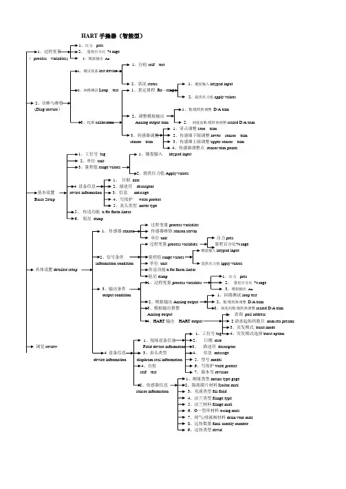
HART手操器(智能型)、压力pres、量程百分比% rnge3、模拟输出Ao1、自检self test2、状况status 1、键盘输入keypad input1、重定量程Re—2、提供压力值apply values、数/模转换调整D/A trim2、调整模拟输出、校准2、刻度的数/模转换调整scaled D/A trim1、零点调整zero trim32、传感器下限调整lower sensor trimsensor trim 3、传感器上限调整upper sensor trim4、传感器调整点sensor trim points、工位号tag 1、键盘输入keypad input2、单位unit、量程值、提供压力值Apply values1、日期date2、描述符descriptor3、信息message4、写保护write protect5、表头类型meter type传送功能x fer fnctn linear阻尼damp过程变量process variables传感器传感器维修senson servin单位unit 压力pres过程变量% rngekeypad input单位unit apply values detailed setup x fer fnctn lineardamp 、压力pres、过程变量2、量程百分比% rnge3、模拟输出Ao1、回路测试loop test、模拟输出2、数/模转换调整D/A trim、模拟输出报警、刻度的数/模转换调整scaled D/A trim查询poll address、HART输出2请求起始码数目num rea preams、突发模式burst mode1、突发模式选择burst option1、日期datereview 、描述符descriptor3、表头类型、信息message5、型号model、自检6、写保护write protecttest 7、版本号revisior1、测量类型means type gage、传感器信息、隔离膜片材料Isoltor matl3、充液类型fill fluid4、法兰类型flange type5、法兰材料flange matl6、O—型环材料o-ring matl7、排气/排液阀材料drain vent matl8、远传数量final asmbly number9、远传类型devid。
怎样使用HART 375对3051系列压力变送器进行组态1 问题提出罗斯蒙特3051系列压力变送器采用HART协议进行通讯,该协议使用了工业标准Bell202频移调制(FSK)技术。
在模拟输出上叠加高频信号可以进行远程通讯.罗斯蒙特采用该技术,能在不影响回路完整性的的情况下,实现同时通讯和输出.如何使用HART协议对3051型压力变送器进行组态,能保证测量仪表设备稳定准确运行。
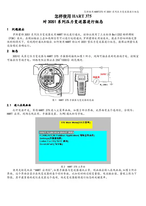
2 组态3051C 或其它压力变送器与HART 375 手操器的接线如图1所示,现场可接在表的电源端子处,控制室可接在信号端子处。
回路电阻应保证在250~1000Ω 的范围内.图1 HART 375手操器与变送器的连接2.1 进入在线画面打开电源开关,等待HART 375进入主菜单画面,如图2所示界面,此界面有五个选项栏,分别为:HART 应用、现场总线应用、手操器设置、与PC通讯和写字板。
图2 HART 375主界面使用光标笔双击“HART 应用栏",如果手操器与变送器通讯正常,则画面应转入在线画面,如图3所示界面,这个界面会显示在线变送器的各个实时参数,比如实时的过程变量值、电流输出值、量程上限与下限值,其中最重要的是仪表设置这个选项,他是变送器能够进行组态的关键菜单。
图3 与变送器连接在线画面2。
2 组态过程在变送器与手操器通讯正常的情况下,可以双击“仪表设置"菜单即可进入变送器的组态菜单,仪表组态画面有5 个选项,如图4所示显示界面。
图4 仪表设置菜单选项A)双击“显示过程变量”后,您可以察看与变送器相关的所有测量参数.B)进入诊断画面,您可以对仪表进行各种校验及回路测试,另外仪表的各项报警也可以查看!C)进入“基本设置”可以进行修改位号、工程单位、量程、仪表的阻尼系数与传递涵数,因此,这是最常用的菜单。
可以双击5个选项的任一个进入该菜单,图5是菜单3“基本设置"的子菜单。
图5 基本设置子菜单注意:单击左箭头可以退回上一级菜单,单击“×”图标退回主菜单(此时可以关机).单击“HOME"退回在线菜单。
使用手册00809-0100-4001,版本 EA 采用HART协议的3051型压力变送器3051 型使用手册00809-0100-4001,版本 EA 3051 型3051 型压力变送器注意在使用产品前务必阅读本手册。
为了确保人身安全和系统安全并使产品达到最佳性能,在产品安装、使用或维修前必须确保已完全理解本手册中的内容。
如此中文版本使用手册个别内容与英文版本描述不同,请以英文版本为准。
免费客户服务热线:800-820-1996 联系当地的罗斯蒙特销售办事处,请拨打:北京 010-********上海 021-********广州 020-********西安 029-********乌鲁木齐 0991-*******警告本手册描述产品的设计用途不包括核级资质应用领域。
将非核级资质产品用于需要核级资质硬件或产品的应用领域会产生错误的读数。
如需罗斯蒙特核级资质产品,请联系当地罗斯蒙特销售代表。
罗斯蒙特 3051 型智能压力变送器受下列一种或多种专利保护:美国专利证书号:4466290;4612812; 4791352; 4798089; 4818994; 4866435;4878012;4988990; 4926340; 5083091; 5122794; 5166678; 5248167;5278543; 5287746; 5329818;5333504; 5585777; 6017143; 6119047;6295875; Des. 317266; Des. 318432; Des 342456。
具体情况取决于相关型号。
其他颁发的及等待颁发的美国和外国专利。
艾默生过程控制有限公司履行所有法律义务以满足欧盟产品要求。
3051 型使用手册00809-0100-4001,版本 EA 3051 型目录第一章简介如何使用手册 . . . . . . . . . . . . . . . . . . . . . . . . . . . . . . . . . . . . . . . .服务支持 . . . . . . . . . . . . . . . . . . . . . . . . . . . . . . . . . . . . . . .包括型号. . . . . . . . . . . . . . . . . . . . . . . . . . . . . . . . . . . . . . . . . . . .变送器概述. . . . . . . . . . . . . . . . . . . . . . . . . . . . . . . . . . . . . . . . . .1-11-11-21-3第二章安装概述 . . . . . . . . . . . . . . . . . . . . . . . . . . . . . . . . . . . . . . . . . . . . . . .安全信息 . . . . . . . . . . . . . . . . . . . . . . . . . . . . . . . . . . . . . . . .. . . .警告 . . . . . . . . . . . . . . . .. . . . . . . . . . . . . . . . . . . . . . . . . .总体描述 . . . . . . . . . . . . . . . . . . . . . . . . . . . . . .. . . . . . . . . . . . .机械描述 . . . . . . . . . . . . .. . . . . . .. . . . .. . . . .. . . . . . . . . . . .量程描述 . . . . . . . . . . . .. . . .. .. . . . . . . . . . . . . . . . .. . . . . .环境描述. . . . . . . . . . . . . . . . . . . . . . . . . . . . . . . . .. . . . . . . . . .安装程序. . . . . . .. . . .. . .. . . . . . . . . . . . . . . . . . . . . . . . . . . . . . . .安装变送器. . . . . . . . . . . . ... . . . . . . . . . . . . . . . . . . . . . . . .过程连接. . . . . . . . . . . . . . . . . . . . . .. . . . . . . . . . . . . . . . . .外壳旋转描述. . . . . . . . . . . . . . . . . . . . . .. . . . . . . . . . . . . . . .设置跳线 . . . . . . . . . . . . . . . . . . . . . . . . . . . . . . . . . . . . . . . .接线并接通电源. . . . . . .. . . . . . . . . . . . .. . . . . . . . . . . . . . .危险场所. . . . . . . . . . . . . . . . . . . . . . . . . . . . . . . . . . . . . . . . . . .变送器外壳接地. . . . . . . . . . . . . . . . . . .. . . . . . . . . . . . . . . . .安装液晶显示器 . . . . . . . . . . . . . . . . . . . . . .. . . . . . . . . . . . . . .305 型和 306 型一体化阀组. . . . . . . . . . . .. . ... . . . . . . . . . . . . .安装程序. . . . . . . . . . .. . . . . . . . . . . . . . . . . . . . . . . . . . .2-12-12-12-22-32-32-42-62-62-112-132-142-162-182-182-192-222-22第三章组态概述 . . . . . . . . . . . . . . . . . . . . . . . . . . . . . . . . . . . . . . . . . . . . . . .安全信息 . . . . . . . . . . . . . . . . . . . . .. . . . . . . . . . . . . . . . . . . . . .报警 . . . .. . . . . . . . . . . . . . . . . . . . . . . . . . . . . . . . . . . . . . .试验台上用 HART 试运行. . . . . . . . . .. . . . . . . . . . . . . . . . . . . .按照手册设置回路. . . . . . . . . . . . . . . . . . . . . . . . . . . . . . . . . . .接线图. . . . . . . . . . . . . . . . . . . . . . . . . . . . . . . . . . . . . . . . . .275 型 HART 通讯装置. . . . . . . . . . . . . . . . . . . . . . . . . . . . . . . .审核组态数据. . . . . . . . . . . . . . . . . . . .. . . . . . . . . .. . . . . . . . . .检查输出. . . . . . . . . . . . . . . . . . . . . . . . . . . . . . . . . . . . . . . . . .过程变量. . . . . . . . . . . . . . . . . . . . . . . . . . . . . . . . . . . . . . . . .传感器温度. . . . . . . . . . . . . . . . . . . . . . . . . . . . . . . . . . . . . .基本设置 . . . . . . . . . . . . . . . . . . . . . . .. . . . . . . . . . . . . . . . . . . . .设置过程变量单位. . . . . . . . . . . . . . .. . .. . . . . . . . . . . . .设置输出 . . . . . . . . . . . . . .. . . . . . . . . . . . . . . . . . . . . . . . . .重置量程 . . . . . . . . . . . . . . . . . . . . . . . . . .. . . . . . . . . . . . . .阻尼 . . . . . . . . .. . . . . . . . . . . . . . . . . . . . . . . . . . . . . . . . . .3-13-13-13-23-23-33-43-73-73-73-83-83-83-93-103-163051 型液晶显示器. . . . . . . . . . . . . . . . . . . . . . . . . . . . . . . . . . . . . . . . . .标准显示组态. . . . . . . . .. . . . . . . . . . . . . . . . . . . . . . . . . .自定义显示组态. . . . . . . . . . . . . . . .. . . . . . . . . . . . . . . . . . 详细设置 . . . . . . . . . . . . . . . . . . . . . . . . . . . . . . . . . . . . . . . . . .故障模式报警和饱和电平. . . . . . . . . . . . . . . . . . . . . . . . . . .触发模式报警和饱和电平. . . . . . . . . . . . . . . . . . . . . . . . . . . .多站式模式报警和饱和值. . . . . . . . . . . . . . . . . . . . . . . . . . . .报警电平检验. . . . . . . . . . . . . . . . . . . . . . . . . . . . . . . . . . . .传感器温度单位 . . . . . . . . . . . . . .. . . . . . . . . . . . . . . . . . . . . 诊断和服务. . . . . . . . . . . . . . . . . . . . . . . . . . . . . . . . . . . . . .变送器测试 . . . . . . . . . . . . . . . . . . . . . . . . . . . . . . . . . . . . . .回路测试 . . . . . . . . . . . . . . . . . . . . . . . . . . . . . . . . . . . . . . . . 先进功能 . . . . . . . . . . . . . . . . . . . . . . . . . . . . . . . . . . . . . . . . .保存、取消和克隆组态数据 . . . . . . . . . . . . . . . . . .. . . . .触发模式 . . . . . . . . . . . .. . . . . . . . . . . . . . . . . . . . . . . . . . . . 多站式通讯 . . . . . . . . . . . . . . . . . . .. . . . . . . . . . . . . . . . . . . . . .改变变送器地址 . . . . . . . . . . . . . . . . . . . . . . . . . . . . . . . . . .与多站式变送器通讯 . . . . . . . . . . . . . . . . . . . . . .. . . . . . . . .对多站式变送器查询. . . . . . . . . . . . . . . . . . . . . 3-16 3-17 3-17 3-19 3-19 3-20 3-20 3-20 3-20 3-21 3-21 3-21 3-22 3-22 3-24 3-25 3-26 3-27 3-27第四章使用和维护概述 . . . . . . . . . . . . . . . . . . . . . . . . . . . . . . . . . . . . . . . . . . . .安全信息 . . . . . . . . . . . . . . . . . . . . . . . . . . . . . . . . . . . . . . . . .警告 . . . . . . . . . . . . . . . . . . . . . . . . . . . . . . . . . . . . . . . . . . .标定 . . . . . . . . . . . . . . . . . . . . . . . . . . . . . . . . . . . . . . . . . . . . . .标定概述 . . . . . . . . . . . . . . . . . . . . . . . . . . . . . . . . . . .确定标定频率 . . . . . . . . . . . . . . . . . . . . . . . .选择微调程序 . . . . . . . . . . . . . . . . . . . . . . . . . . . . . .传感器微调 . . . . . . . . . . . . . . . . . . . . . . . . . . . . . . . . . . . . . .零点微调 . . . . . . . . . . . . . . . . . . . . . . . . . . . . . . . . . . . . . .全量程微调 . . . . . . . . . . . . . . . . . . . . . . . . . . . . . . . . . . . . .恢复工厂微调 . . . . . . . . . . . . . . . . . . . . . . . . . . . . . . . . . . . .模拟输出微调 . . . . . . . . . . . . . . . . . . . . . . . . . . . . . . . . . . .数/模转换微调. . . . . . . . . . . . . . . . . . . . . . . . . . . . . . . . . .应用其他刻度进行数/模转换微调. . . . . . . . . . . . . . . . . .静压补偿 . . . . . . . . . . . . . . . . . . . . . . . . . . . . . . . . . . . . . .诊断信息 . . . . . . . . . . . . . . . . . . . . . . . . . . . . . . . . .本机零点及量程(本机键)软件锁定 . . . . . . . . . . . . . . . .本机零点及量程的实体拆除(本机键) . . . . . . . . . . . . .选择低功耗输出量程 . . . . . . . . . . . . . . . . . . . . . .详细设置 . . . . . . . . . . . . . . . . . . . . . . . . . . . . . . . . . . . . . . . . . .本机量程与零点控制(本机键). . . . . . . . . . . . . . . . . .4-14-14-14-24-34-44-64-64-74-84-94-104-104-114-124-144-194-194-204-204-20第五章故障检修概述 . . . . . . . . . . . . . . . . . . . . . . . . . . . . . . . . . . . . . . . . . . . . . . .安全信息 . . . . . . . . . . . . . . . . . . . . . . . . . . . . . . . . . . . . . . . . .警告 . . . . . . . . . . . . . . . . . . . . . . . . . . . . . . . . . . . . . . . . . . . .拆卸变送器之前. . . . . . . . . . . . . . . . . . . . . . . . .拆卸程序 . . . . . . . . . . . . . . . . . . . . . . . . . . . . . . . . . . .从服务地点拆除变送器 . . . . . . . . . . . . . . . . . . . . . .拆除端子块 . . . . . . . . . . . . . . . . . . . . . . . . . . . . . .拆除电子线路板 . . . . . . . . . . . . . . . . . . . . . . . . . . . .从电子元件外壳中拆除传感器模块 . . . . . .5-15-15-15-35-35-35-45-45-5目录-2使用手册00809-0100-4001,版本 EA 3051 型重新装配程序 . . . . . . . . . . . . . . . . . . . . . . . . . . . . . . . . . . .安装电子线路板 . . . . . . . . . . . . . . . . . . . . . . . . . . . . .安装端子块 . . . . . . . . . . . . . . . . . . . . . . . . . . . . . . . .重新装配过程传感器本体 . . . . . . . . . . . . . . . . . . . . . 5-5 5-6 5-6 5-7附录 A 参考信息性能说明 . . . . . . . . . . . . . . . . . . . . . . . . . . . . . . . . .详细性能说明. . . . . . . . . . . . . . . . . . . . . . . . . .参考精度 . . . . . . . . . . . . . . . . . . . . . . . . . . . . . . . . . . . .环境温度. . . . . . . . . . . . . . . . . . . . . . . . . . . . . . . . . . .静压影响 . . . . . . . . . . . . . . . . . . . . . . . . . . . . . . . . . . .动态性能 . . . . . . . . . . . . . . . . . . . . . . . . . . . . . . . . . .安装位置影响 . . . . . . . . . . . . . . . . . . . . . . . . . . . . . . . .振动影响 . . . . . . . . . . . . . . . . . . . . . . . . . . . . . . . . . . . . . . . .电源影响 . . . . . . . . . . . . . . . . . . . . . . . . . . . . . . . . . . . .射频干扰影响 . . . . . . . . . . . . . . . . . . . . . . . . . . . . . . . . . . . . . . . . . . .耐瞬变电压保护 . . . . . . . . . . . . . . . . . . . . . . . . . . . . . . . . . . . .功能说明 . . . . . . . . . . . . . . . . . . . . . . . . . . . . . . . . . . .量程及传感器极限值 . . . . . . . . . . . . . . . . . . . . . . . . . . . . . . . .形体说明 . . . . . . . . . . . . . . . . . . . . . . . . . . . . . . . . . . .尺寸图 . . . . . . . . . . . . . . . . . . . . . . . . . . . . . . . . . . . .订购信息 . . . . . . . . . . . . . . . . . . . . . . . . . . . . . . . . . . . . .零件清单. . . . . . . . . . . . . . . . . . .. . . . . . . . . . . . . . . . . . . . . . .选项 . . . . . . . . . . . . . . . . . . . . . . . . . . . . . . . . . . . . . . . . . . . . . . .HART 协议组态数据表 . . . . . . . . . . . . . . . . . . . . .A-1A-2A-2A-3A-4A-4A-5A-5A-5A-5A-5A-6A-6A-11A-13A-21A-35A-45A-50附录 B 产品认证概述 . . . . . . . . . . . . . . . . . . . . . . . . . . . . . . . . . . . . . . . . . . . . . . .安全信息 . . . . . . . . . . . . . . . . . . . . . . . . . . . . . . . . . . . . . . . . .警告 . . . . . . . . . . . . . . . . . . . . . . . . . . . . . . . . . . . . . . . . . . . .通过认证的制造场所 . . . . . . . . . . . . . . . . . . . . . . . . . . .欧盟指令信息 . . . . . . . . . . . . . . . . . . . . . . . . . . . . . .ATEX 指令 . . . . . . . . . . . . . . . . . . . . . . . . . . . . . . . . . . . . . . . .欧盟压力设备指令(PED)(97/23/EC) . . . . .电磁兼容性(EMC) . . . . . . . . . . . . . . . . . . . . . .其他重要指南 . . . . . . . . . . . . . . . . . . . . . . . . . . . . . . .工厂互检普通场所认证 . . . . . . . . . . . . . . .危险场所认证 . . . . . . . . . . . . . . . . . . . . . . . . . .北美认证. . . . . . . . . . . . . . . . . . . . . . . . . . . . .欧盟认证 . . . . . . . . . . . . . . . . . . . . . . . . . . . . . . . . .日本认证 . . . . . . . . . . . . . . . . . . . . . . . . . . . . . . . .澳大利亚认证 . . . . . . . . . . . . . . . . . . . . . . . . . . . . . . . . .认证组合 . . . . . . . . . . . . . . . . . . . . . . . . . . . .认证图纸. . . . . . . . . . . . . . . . . . . . . . . . . . . . . . . . . . . . . . . .工厂互检03031-1019 . . . . . . . . . . . . . . . . . . . . . . . . . . . . . .加拿大标准协会(CSA)03031-1024 . . . . . . . . .澳大利亚标准协会(SAA)03031-1026 . . . . . . . .B-1B-1B-1B-2B-2B-2B-3B-3B-3B-3B-4B-4B-5B-7B-7B-8B-9B-9B-21B-30目录-33051 型使用手册00809-0100-4001,版本 EA 3051 型第一章简介如何使用本手册本手册所含章节提供罗斯蒙特 3051S 型智能压力变送器系列测量装置安装、使用和维护信息。


产品说明书00813-0106-4016, Rev UC2023 年 3 月Rosemount™差压液位变送器和 1199 远传密封件应用■液位、流量、压力、界面、密度■极热和极冷环境■腐蚀、堵塞或粘滞过程■卫生要求■特殊过程连接件成熟、可靠和创新的技术使用资产位号随时获取信息新发运设备包含一个唯一的二维码资产位号,您可以通过它直接从设备访问序列化信息。
通过此功能,您可以:■在您的 MyEmerson 账号上访问设备图纸、图表、技术文档和故障排除信息■优化维修和保持效率的平均时间■确保您定位了正确的设备■省去耗时的先定位和抄录铭牌再查看资产信息的工作罗斯蒙特液位变送器此液位变送器将世界先进的罗斯蒙特压力仪表与直接安装密封件相结合,全部集成为一个型号。
Rosemount 3051SAL、3051L 和 2051L型液位变送器■全焊接系统具备突出的系统可靠性■无线组态提供新数据访问■使用全面的过程连接产品、灌充液、直接安装或毛细管连接件和材料可连接到几乎任何过程■利用 QZ 选件量化和优化整个系统的性能内容成熟、可靠和创新的技术 (2)Rosemount 3051S 电子远程传感器 (ERS™) 系统 (6)Rosemount 3051S Scalable™液位变送器 (26)用于 Rosemount 3051SAL 的法兰密封件 (40)Rosemount 3051L 液位变送器订购信息 (65)Rosemount 2051L 液位变送器 (77)直接安装式密封系统订购信息 (86)远传安装式密封系统订购信息 (92)法兰密封件 (98)螺纹密封件 (123)卫生型密封件 (129)专业密封件 (144)技术规格 (153)产品认证 (173)尺寸图 (216)2023 年 3 月/Rosemount罗斯蒙特 Tuned-System ™ 组件优化结果罗斯蒙特 Tuned-System 组件在高压连接件上采用直接安装密封件,在低压连接件上则采用远程安装(毛细管式)密封件。
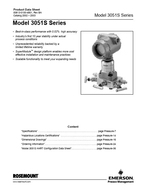
Product Data Sheet00813-0100-4801, Rev BA Catalog 2002 – 2003Model 3051S Series•Best-in-class performance with 0.02% high accuracy •Industry's first 10 year stability under actual process conditions•Unprecedented reliability backed by a limited lifetime warranty•SuperModule ™ design platform enables more cost effective installation and maintenance practices •Scalable functionality to meet your expanding needsContent“Specifications” . . . . . . . . . . . . . . . . . . . . . . . . . . . . . . . . . . . . . . . . . . . . . page Pressure-7“Hazardous Locations Certifications” . . . . . . . . . . . . . . . . . . . . . . . . . . . page Pressure-14“Dimensional Drawings” . . . . . . . . . . . . . . . . . . . . . . . . . . . . . . . . . . . . . page Pressure-16“Ordering Information”. . . . . . . . . . . . . . . . . . . . . . . . . . . . . . . . . . . . . . . page Pressure-24“Model 3051S HART Configuration Data Sheet”. . . . . . . . . . . . . . . . . . . page Pressure-36Model 3051S SeriesProduct Data Sheet00813-0100-4801, Rev BACatalog 2002 – 2003Model 3051S SeriesPressure-4Success goes beyond the transmitter to an enabling platformIntroducing the next evolution in measurement, the Model 3051S Series. This scalable platform enablesimplementation of the best measurement practices from design and installation to maintenance and operations.Best-in-class performance with 0.04% accuracy The Model 3051S delivers cutting edge performance beginning with the SuperModule platform. Among the many advances, Saturn ™ sensing technology incorporates a secondary sensor to optimize performance and expand diagnostic capabilities.Industry's first 10 year stability under actual process conditionsStability begins with an all-welded, 316L SSThermetically sealed SuperModule which houses the single board electronics, thus eliminating moisture and field contaminant effects.Unprecedented reliability backed by a limited lifetime warrantyThe SuperModule design delivers the most reliable platform to further enhance installation practices and advanced diagnostic capabilities.SuperModule design platform enables more cost effective installation and maintenance practices A scalable architecture enables direct mounting of the SuperModule for maximum performance and reliability. The flexible remote mount meter provides access to all digital communications and diagnostics.Scalable functionality to meet your expanding needsFrom basic process variable generation to advanced PlantWeb ™ functionality and highly integrated measurement solutions, the Model 3051S Series meets every application requirement.Rosemount ® Pressure SolutionsModel 3095MV Mass Flow TransmitterAccurately measures differential pressure, static pressure and process temperature to dynamically calculate fully compensated mass flow. See product data sheet 00813-0100-4716.Model 305 and 306 Integral Manifolds Factory-assembled, calibrated and seal-tested manifolds reduce on-site installation costs. See product data sheet 00813-0100-4733.Model 1199 Diaphragm SealsProvides reliable, remote measurements of process pressure and protects the transmitter from hot,corrosive, or viscous fluids. See product data sheet 00813-0100-4016.Model 1195 Integral Orifice andProPlate/Mass ProPlate FlowmetersConvenient ready-to-install assembly designed for small-bore flow measurement of any clean gas, liquid, or vapor. See product data sheet 00813-0100-4686.Annubar Flowmeter SeriesA series of highly accurate and repeatableinsertion-type flowmeters available in 2-in. to 72-in. (50.8 to 1829 mm) line sizes. See product data sheet 00813-0100-4809.Model 405P Compact OrificeA wafer style primary element with an integral three-valve manifold. See product data sheet00813-0100-4810.Product Data Sheet00813-0100-4801, Rev BA Catalog 2002 – 2003Pressure-5Model 3051S SeriesModel 3051S Selection GuideSELECT AN INSTRUMENT CONFIGURATIONModel 3051S_C Coplanar ™ Differential, Gage, and AbsoluteSee ordering information on page Pressure-24.•Performance up to 0.04% accuracy with 200:1 turndown •Available 10 year stability and limited lifetime warranty •Coplanar platform enables integrated manifold, primary element and diaphragm seal solutions •Calibrated spans from 0.1 inH 2O to 4000 psi (0,25 mbar to 276 bar)•316L SST, Hastelloy ® C, Monel ®, Tantalum, gold-plated Monel, or gold-plated 316L SST process isolatorsModel 3051S_T In-Line Gage and AbsoluteSee ordering information on page Pressure-28.•Performance up to 0.04% accuracy with 200:1 turndown•Available 10 year stability and limited lifetime warranty•Calibrated spans from 0.15 to 10000 psi (10,3 mbar to 689 bar)•Multiple process connections available •316L SST and Hastelloy C process isolatorsModel 3051S_L Liquid LevelSee ordering information on page Pressure-30.•Performance up to 0.065% accuracy with 100:1 turndown•Flush, 2-, 4-, and 6-in. extended diaphragms •Multiple fill fluids available•316L SST, Hastelloy, or Tantalum wetted materialsC O P L A N A R /3151_E 27BProduct Data Sheet00813-0100-4801, Rev BACatalog 2002 – 2003Model 3051S SeriesPressure-6CONSIDER PERFORMANCE REQUIREMENTS DETERMINE HOUSING AND PROCESS CONNECTIONUltraClassic•0.04% accuracy, 200:1 turndown•10 year stability and limited lifetime warranty•0.065% accuracy, 100:1 turndown •5 year stability••Product Data Sheet00813-0100-4801, Rev BA Catalog 2002 – 2003Pressure-7Model 3051S SeriesSpecificationsPERFORMANCE SPECIFICATIONSFor zero-based spans, reference conditions, silicone oil fill, SST materials, Coplanar flange (Model 3051S_C) or 1/2 in.- 18 NPT (Model 3051S_T) process connections, digital trim values set to equal range points.Conformance to specification (±3 Sigma)Technology leadership, advanced manufacturing techniques and statistical process control ensure specification conformance to at least ±3 sigma.Reference AccuracyTotal PerformanceLong Term StabilityUltra (1) (2)Classic (1)(2)Model 3051S_CD, CG±0.04% of span; for spans less than 10:1, accuracy =Range 1: ±0.09% of span;for spans less than 15:1, accuracy =Range 0: ±0.09% of span; for spans less than 2:1,accuracy= ±0.045% of URL±0.065% of span; for spans less than 10:1, accuracy =Range 1: ±0.10% of span;for spans less than 15:1, accuracy =Range 0: ±0.10% of span; for spans less than 2:1,accuracy= ±0.05% of URLModel 3051S_T±0.04% of span; for spans less than 10:1, accuracy =±0.065% of span; for spans less than 10:1, accuracy =Model 3051S_CA±0.04% of span; for spans less than 10:1, accuracy =Range 0: ±0.075% of span;for spans less than 5:1, accuracy =±0.065% of span; for spans less than 10:1, accuracy =Range 0: ±0.075% of span;for spans less than 5:1, accuracy =Model 3051S_LNot available±0.065% of span; for spans less than 10:1, accuracy =(1)Stated reference accuracy includes terminal based linearity, hysteresis, and repeatability.(2)For F OUNDATION fieldbus transmitters, use calibrated range in place of span.0.0050.0035+URLSpan ------------% of Span±0.0150.005+URLSpan ------------% of Span±0.0150.005+URLSpan ------------% of Span±0.0250.005+URLSpan ------------% of Span±0.004URLSpan ------------% of Span±0.0065URLSpan ------------% of Span±0.004URL Span ------------% of Span±0.0250.01+URL Span ------------% of Span±0.0065URL Span ------------% of Span±0.0250.01+URL Span ------------% of Span±0.0150.005+URL Span ------------% of Span±Ultra (1)Classic (1)Model 3051S_C CD Ranges 2-3 and CG Ranges 2-5±0.125% of span; for ±50°F (28°C) temperaturechanges, 0-100% relative humidity, up to 1000 psi (68,9 bar) line pressure (CD only), from 1:1 to 5:1 rangedown.±0.15% of span; for ±50°F (28°C) temperature changes, 0-100% relative humidity, up to 1000 psi (68,9 bar) line pressure (CD only), from 1:1 to 5:1 rangedown.(1)Total performance is based on combined errors of reference accuracy, ambient temperature effect, and line pressure effect.UltraClassicModel 3051S_C CD Ranges 2-3 and CG Ranges 2-5±0.20% of URL for 10 years; for ±50°F (28°C)temperature changes, 0-100% relative humidity, up to 1000 psi (68,9 bar) line pressure (CD only)±0.125% of URL for 5 years; for ±50°F (28°C)temperature changes, 0-100% relative humidity, up to 1000 psi (68,9 bar) line pressure (CD only)Product Data Sheet00813-0100-4801, Rev BACatalog 2002 – 2003Model 3051S SeriesPressure-8Dynamic PerformanceAmbient Temperature Effect per 50 °F (28 °C)Line Pressure Effect per 1000 psi (69 bar)For line pressures above 2000 psi (137,9 bar) and ranges 4-5, see the Model 3051S Series reference manual (document number 00809-0100-4801).Mounting Position EffectsUltraClassicModel 3051S_CD, CG± (0.009% URL + 0.04% span) from 1:1 to 10:1± (0.018% URL + 0.08% span) from 10:1 to 200:1Range 0: ± (0.25% URL + 0.05% span)Range 1: ± (0.1% URL + 0.25% span)± (0.0125% URL + 0.0625% span) from 1:1 to 5:1± (0.025% URL + 0.125% span) from 5:1 to 100:1Range 0: ± (0.25% URL + 0.05% span)Range 1: ± (0.1% URL + 0.25% span)Model 3051S_T± (0.0125% URL + 0.125% span) from 1:1 to 10:1± (0.025% URL + 0.125% span) from 10:1 to 200:1Range 1:± (0.025% URL + 0.125% span) from 1:1 to 10:1± (0.05% URL + 0.125% span) from 10:1 to 200:1Range 5: ± (0.1% URL + 0.15% span)± (0.025% URL + 0.125% span) from 1:1 to 30:1± (0.035% URL + 0.125% span) from 30:1 to 100:1Range 1:± (0.025% URL + 0.125% span) from 1:1 to 10:1± (0.05% URL + 0.125% span) from 10:1 to 100:1Range 5: ± (0.1% URL + 0.15% span)Model 3051S_CA± (0.025% URL + 0.125% span) from 1:1 to 30:1± (0.035% URL + 0.125% span) from 30:1 to 200:1Range 0: ± (0.1% URL + 0.25% span)± (0.025% URL + 0.125% span) from 1:1 to 30:1± (0.035% URL + 0.125% span) from 30:1 to 100:1Range 0: ± (0.1% URL + 0.25% span)Model 3051S_LNot availableSee Rosemount Instrument Toolkit ™UltraClassicModel 3051S_CDZero Error(1)± 0.035% of URL for line pressures from 0 to 2000 psi (0 to 137,9 bar)Range 0: ± 0.125% URL per 100 psi (6,89 bar)Range 1: ± 0.25% URLSpan Error± 0.1% of readingRange 0: ± 0.15% of reading per 100 psi (6,89 bar)Range 1: ± 0.4% of reading(1)Zero error can be calibrated outZero Error (1)± 0.05% URL for line pressures from 0 to 2000 psi (0 to 137,9 bar)Range 0: ± 0.125% URL per 100 psi (6,89 bar)Range 1: ± 0.25% URLSpan Error± 0.1% of readingRange 0: ± 0.15% of reading per 100 psi (6,89 bar)Range 1: ± 0.4% of readingUltra and ClassicModel 3051S_C Zero shifts up to ±1.25 inH 2O (3,11 mbar), which can be calibrated out; no span effectModel 3051S_LWith liquid level diaphragm in vertical plane, zero shift of up to 1 inH 2O (25,4 mmH 2O); with diaphragm in horizontal plane, zero shift of up to 5inH 2O (127 mmH 2O) plus extension length on extended units; all zero shifts can be calibrated out; no span effectModel 3051S_T and Model 3051S_CAZero shifts to 2.5 inH2O (63,5 mmH20), which can be calibrated out; no span effectProduct Data Sheet00813-0100-4801, Rev BA Catalog 2002 – 2003Pressure-9Model 3051S SeriesVibration EffectAll Models:Less than ±0.1% of URL when tested per the requirements of IEC60770-1 field or pipeline with high vibration level (10-60 Hz 0.21mm peak to peak displacement / 60-2000 Hz 3g).Option Codes 1J, 1K, 1LLess than ±0.1% of URL when tested per the requirements of IEC60770-1 field with general application or pipeline with low vibration level (10-60 Hz 0.15mm peak to peak displacement / 60-2000 Hz 2g).Power Supply EffectAll Models:Less than ±0.005% of calibrated span per voltRFI EffectsAll Models:±0.1% of span from 20 to 1000 MHz and for field strength up to 30 V/mTransient Protection (Option T1)All Models:Meets IEEE Standard 587, Category B1 kV crest (10 × 1000 microseconds)3 kV crest (8 × 20 microseconds)6 kV crest (12 × 50 microseconds)Meets IEEE Standard 472, Surge Withstand CapabilitySWC 2.5 kV crest, 1 MHz wave form General Specifications:Response Time: < 1 nanosecondPeak Surge Current: 5000 amps to housing Peak Transient Voltage: 100 V dc Loop Impedance: < 25 ohmsApplicable Standards: IEC 801-4, IEC 801-5NOTE:Calibrations at 68 °F (20 °C) per ASME Z210.1(ANSI)FUNCTIONAL SPECIFICATIONSRange and Sensor LimitsR a n g eMinimum Span 3051S_Range and Sensor Limits 3051S_Ultra Classic Upper (URL)Lower (LRL)Model 3051S_CD Model 3051S_CGModel 3051S_LD00.1 inH 2O (0,25 mbar)0.1 inH 2O (0,25 mbar) 3.0 inH 2O (7,5 mbar)–3.0 inH 2O (–7,5 mbar)NA NA 10.5 inH 2O (1,24 mbar)0.5 inH 2O (1,24 mbar)25.0 inH 2O (62,3 mbar)–25.0 inH 2O (–62,3 mbar)–25.0 inH 2O (–62,3 mbar)–25.0 inH 2O (–62,3 mbar)2 1.3 inH 2O (3,11 mbar) 2.5 inH 2O (6,23 mbar)250.0 inH 2O (0,62 bar)–250.0 inH 2O (–0,62 bar)–250.0 inH 2O (–0,62 bar) –250.0 inH 2O (–0,62 bar)3 5.0 inH 2O (12.4 mbar)10.0 inH 2O (24,9 mbar)1000.0 inH 2O (2,49 bar)–1000.0 inH 2O (-2,49 bar)0.5 psia (34,5 mbar)–1000.0 inH 2O (–2,49 bar)4 1.5 psi (103.4 mbar) 3.0 psi (206,8 mbar)300.0 psi (20,7 bar)–300.0 psi (–20,7 bar)0.5 psia (34,5 mbar)–300.0 psi (–20,7 bar)510.0 psi (689,5 mbar)20.0 psi (1,38 bar)2000.0 psi (137,9 bar)– 2000.0 psi (–137,9 bar)0.5 psia (34,5 mbar)– 2000.0 psi (–137,9 bar)Model 3051S_CA Range and Sensor LimitsMinimum SpanUpper (URL)Lower (LRL)Range UltraClassic00.167 psia (11,5 mbar)0.167 psia (11,5 mbar) 5 psia (0,34 bar)0 psia (0 bar) 10.3 psia (20,7 mbar)0.3 psia (20,7 mbar) 30 psia (2,07 bar) 0 psia (0 bar) 20.75 psia (51,7 mbar) 1.5 psia (0,103 bar) 150 psia (10,34 bar) 0 psia (0 bar) 3 4 psia (275,8 mbar)8 psia (0,55 bar) 800 psia (55,16 bar) 0 psia (0 bar) 420 psia (1,38 bar)40 psia (2,76 bar)4000 psia (275,8 bar)0 psia (0 bar)Product Data Sheet00813-0100-4801, Rev BACatalog 2002 – 2003Model 3051S SeriesPressure-10ServiceLiquid, gas, and vapor applications4–20 mA (output code A)Zero and Span AdjustmentZero and span values can be set anywhere within the range.Span must be greater than or equal to the minimum span.OutputTwo-wire 4–20 mA is user-selectable for linear or square root output. Digital process variable superimposed on 4–20 mA signal, available to any host that conforms to the HART protocol.Power SupplyExternal power supply required. Standard transmitter (4–20 mA) operates on 10.5 to 42.4 V dc with no load.Load LimitationsMaximum loop resistance is determined by the voltage level of the external power supply, as described by:F OUNDATION fieldbus (output code F)Power SupplyExternal power supply required; transmitters operate on 9.0 to 32.0 V dc transmitter terminal voltage.Current Draw17.5 mA for all configurations (including LCD meter option)Overpressure LimitsTransmitters withstand the following limits without damage:Model 3051S_CD, CG Range 0: 750 psi (51,7 bar)Range 1: 2000 psig (137,9 bar)Ranges 2–5: 3626 psig (250,0 bar)4500 psig (310,3 bar) for Option Code P9Model 3051S_CARange 0: 60 psia (4,13 bar)Range 1: 750 psia (51,7 bar)Range 2: 1500 psia (103,4 bar)Range 3: 1600 psia (110,3 bar)Range 4: 6000 psia (413,7 bar)Model 3051S_TG, TA Range 1: 750 psi (51,7 bar)Range 2: 1500 psi (103,4 bar)Range 3: 1600 psi (110,3 bar)Range 4: 6000 psi (413,7 bar)Range 5: 15000 psi (1034,2 bar)Model 3051S_LD, LGLimit is 0 psia to the flange rating or sensor rating, whichever is lower (see the table below).Static Pressure LimitModel 3051S_CD OnlyOperates within specifications between static line pressures of 0.5 psia and 3626 psig;4500 psig (310,3 bar) for Option Code P9Range 0: 0.5 psia to 750 psig (0,03 to 51,71 bar)Range 1: 0.5 psia to 2000 psig (0,03 to137,90 bar)Model 3051S_T Range and Sensor LimitsRange Minimum SpanUpper (URL)Lower (LRL) (Abs.)Lower (1) (LRL) (Gage)UltraClassic 10.15 psi (10,3 mbar)0.3 psi (20,7 mbar)30 psi (2,07 bar)0 psia (0 bar)–14.7 psig (–1,01 bar)20.75 psi (51,7 mbar) 1.5 psi (0,103 bar)150 psi (10,34 bar)0 psia (0 bar)–14.7 psig (–1,01 bar)3 4 psi (275,8 mbar)8 psi (0,55 bar)800 psi (55,16 bar)0 psia (0 bar)–14.7 psig (–1,01 bar)420 psi (1,38 bar)40 psi (2,76 bar)4000 psi (275,8 bar)0 psia (0 bar)–14.7 psig (–1,01 bar)51000 psi (68,9 bar)2000 psi (137,9 bar)10000 psi (689,5 bar)0 psia (0 bar)–14.7 psig (–1,01 bar)(1)Assumes atmospheric pressure of 14.7 psig.L o a d (O h m s )Communication requires a minimum loop resistance of 250 ohms.Max. Loop Resistance = 43.5 (Power Supply Voltage – 10.5)StandardTypeCS RatingSST RatingANSI/ASME Class 150285 psig 275 psig ANSI/ASME Class 300740 psig 720 psig ANSI/ASME Class 6001480 psig 1440 psigAt 100 °F (38 °C), the rating decreaseswith increasing temperature.DIN PN 10–4040 bar 40 bar DIN PN 10/1616 bar 16 bar DIN PN 25/4040 bar 40 barAt 248 °F (120 °C), the rating decreaseswith increasing temperature.Product Data Sheet00813-0100-4801, Rev BA Catalog 2002 – 2003Pressure-11Model 3051S SeriesBurst Pressure LimitsBurst pressure on Coplanar or traditional process flange is 10000 psig (689,5 bar).Burst pressure for the Model 3051S_T is:Ranges 1–4: 11000 psi (758,4 bar)Range 5: 26000 psig (1792,64 bar)Temperature LimitsAmbient–40 to 185 °F (–40 to 85 °C)With integral meter: –4 to 175 °F (–20 to 80 °C)Storage–50 to 230 °F (–46 to 110 °C)With integral meter: –40 to 185 °F (–40 to 85 °C)Process Temperature Limits At atmospheric pressures and above.Humidity Limits0–100% relative humidityTurn-On TimePerformance within specifications less than 2.0 seconds after power is applied to the transmitterVolumetric DisplacementLess than 0.005 in 3 (0,08 cm 3)DampingAnalog output response to a step input change is user-selectable from 0 to 60 seconds for one time constant. This software damping is in addition to sensor module response time.Failure Mode AlarmHART 4-20mA (output code A)If self-diagnostics detect a gross transmitter failure, the analog signal will be driven offscale to alert the user. Rosemount standard, NAMUR, and custom alarm levels are available (see Table 1 below).High or low alarm signal is software-selectable orhardware-selectable via the optional switch (option D1).F OUNDATION Fieldbus (output code F)The AI block allows the user to configure HI-HI, HI, LO, or LO-LO, alarms.PHYSICAL SPECIFICATIONSElectrical Connections1/2–14 NPT, G 1/2, and M20 × 1.5 (CM20) conduit. HART interface connections fixed to terminal block for output code A.Process ConnectionsModel 3051S_C1/4–18 NPT on 21/8-in. centers1/2–14 NPT and RC 1/2 on 2 in.(50.8mm), 21/8 in. (54.0 mm), or 21/4-in. (57.2mm) centers (process adapters)Model 3051S_T1/2–14 NPT female, Non-Threaded instrument flange(available in SST for Range 1–4 transmitters only), G 1/2 A DIN 16288 Male (available in SST for Range 1–4 transmitters only), or Autoclave type F-250-C (Pressure relieved 9/16–18 gland thread; 1/4 OD high pressure tube 60° cone; available in SST for Range 5 transmitters only).Model 3051S_C CoplanarSilicone Fill Sensor (1)(1)Process temperatures above 185 °F (85 °C) require derating theambient limits by a 1.5:1 ratio.with Coplanar Flange –40 to 250 °F (–40 to 121 °C)(2)(2)220 °F (104 °C) limit in vacuum service; 130 °F (54 °C) forpressures below 0.5 psia.with Traditional Flange –40 to 300 °F (–40 to 149 °C)(2)with Level Flange–40 to 300 °F (–40 to 149 °C)(2)with Model 305 Integral Manifold–40 to 300 °F (–40 to 149 °C)(2)Inert Fill Sensor (1)0 to 185 °F (–18 to 85 °C)(3)(4)(3)160 °F (71 °C) limit in vacuum service.(4)Not available for Model 3051S_CA.Model 3051S_T In-Line (Process Fill Fluid)Silicone Fill Sensor (1)–40 to 250 °F (–40 to 121 °C)(2)Inert Fill Sensor (1)–22 to 250 °F (–30 to 121 °C)(2)Model 3051S_L Low-Side Temperature Limits Silicone Fill Sensor (1)–40 to 250 °F (–40 to 121 °C)(2)Inert Fill Sensor (1)0 to 185 °F (–18 to 85 °C)(2)Model 3051S_L High-Side Temperature Limits(Process Fill Fluid)Syltherm ®XLT–100 to 300 °F (–73 to 149 °C)D.C.® Silicone 704(5)(5)Upper limit of 600 °F (315 °C) is available with Model 1199 sealassemblies mounted away from the transmitter with the use of capillaries and up to 500 °F (260 °C) with direct mount extension.60 to 400 °F (15 to 205 °C)D.C. Silicone 200–40 to 400 °F (–40 to 205 °C)Inert–50 to 350 °F (–45 to 177 °C)Glycerin and Water 0 to 200 °F (–18 to 93 °C)Neobee M-20®0 to 400 °F (–18 to 205 °C)Propylene Glycol and Water0 to 200 °F (–18 to 93 °C)TABLE 1. Alarm ConfigurationHigh AlarmLow Alarm Rosemount≥ 21.75 mA ≤ 3.75 mA NAMUR compliant (1)(1)Analog output levels are compliant with NAMUR recommendationNE 43 (June 27, 1996)≥ 22.5 mA ≤ 3.6 mA Custom levels (2)(2)Low alarm must be 0.1 mA less than low saturation and high alarmmust be 0.1 mA greater than high saturation.20.2 - 23.0 mA3.6 - 3.8 mAProduct Data Sheet00813-0100-4801, Rev BACatalog 2002 – 2003Model 3051S SeriesPressure-12Model 3051S_LHigh pressure side: 2 in.(50.8mm), 3 in. (72 mm), or 4-in.(102mm), ASME B 16.5 (ANSI) Class 150, 300 or 600 flange; 50, 80 or 100 mm, DIN 2501 PN 40 or 10/16 flange Low pressure side: 1/4–18 NPT on flange 1/2–14 NPT on process adapterProcess-Wetted PartsProcess Isolating DiaphragmsDrain/Vent Valves316 SST, Hastelloy C-276, or Monel 400 material (Monel is not available with Model 3051S_L.)Process Flanges and AdaptersPlated carbon steel, CF-8M (Cast version of 316 SST, material per ASTM-A743), CW-12MW (Cast version of Hastelloy C-276, material per ASTM A494), M-30C (Cast version of Monel 400, material per ASTM A494).Wetted O-ringsGlass-filled TFE(Graphite-filled TFE with isolating diaphragm Option Code 6)Model 3051S_L Process Wetted PartsFlanged Process Connection (Transmitter High Side)Process Diaphragms, Including Process Gasket Surface 316L SST, Hastelloy C-276, or Tantalum ExtensionCF-3M (Cast version of 316L SST, material per ASTM-A743), or CW-12MW (Cast version of Hastelloy C, material ASTM A494); fits schedule 40 and 80 pipe Mounting FlangeZinc-cobalt plated CS or 316 SSTReference Process Connection (Transmitter Low Side)Isolating Diaphragms 316L SST or Hastelloy C-276Reference Flange and AdapterCF-3M (Cast version of 316L SST, material per ASTM-A743)Non-Wetted PartsElectronics HousingLow-copper aluminum or CF-3M (Cast version of 316L SST) NEMA 4X, IP 65, IP 66Coplanar Sensor Module Housing CF-3M (Cast version of 316L SST)BoltsPlated carbon steel per ASTM A449, Type 1: Austenitic 316 SST, ASME B 16.5 (ANSI)/ASTM-A-193-B7M, or Monel Sensor Module Fill FluidSilicone or inert halocarbon (Inert is not available with Model 3051S_CA.) In-Line series uses Fluorinert ® FC-43Process Fill Fluid (Liquid Level Only)Model 3051S_L: Syltherm XLT, D.C. Silicone 704, D.C. Silicone 200, inert, glycerin and water, Neobee M-20, propylene glycol and water Paint Polyurethane Cover O-rings Buna-NOrdinary Locations CertificationsAs standard, the transmitter has been examined and tested to determine that the design meets basic electrical, mechanical, and fire protection requirements by FM, a nationally recognized testing laboratory (NRTL) as accredited by the Federal Occupational Safety and Health Administration (OSHA).Isolating Diaphragm Material Model 3051S_CD, CG T CA L 316L SST•••S e e B e l o wHastelloy C-276 ®•••Monel 400••Tantalum•Gold-plated Monel 400••Gold-plated 316L SST ••Shipping Weights for Model 3051S TABLE 2. SuperModule weightsTABLE 3. Transmitter weights without optionsTABLE 4. Model 3051S_L weights without optionsTABLE 5. Transmitter option weightsSuperModule Weight in lb. (kg)Coplanar (1)(1)Flange and bolts not included.3.1 (1,4)In-Line1.4 (0,64)Complete Transmitter (1)(1)Fully functional transmitter with terminal block,covers, and SST flange.Add Weight In lb (kg)Model 3051S_C with junction box housing 6.9 (3,1)Model 3051S_T with junction box housing 3.3 (1,5)Model 3051S_C with PlantWeb housing 7.2 (3,3)Model 3051S_T with PlantWeb housing3.6 (1,6)FlangeFlush lb. (kg)2-in. Ext.lb (kg)4-in. Ext.lb (kg)6-in. Ext.lb (kg)2-in., 15012.5 (5,7)———3-in., 15017.5 (7,9)19.5 (8,8)20.5 (9,3)21.5 (9,7)4-in., 15023.5 (10,7)26.5 (12,0)28.5 (12,9)30.5 (13,8)2-in., 30017.5 (7,9)———3-in., 30022.5 (10,2)24.5 (11,1)25.5 (11,6)26.5 (12,0)4-in., 30032.5 (14,7)35.5 (16,1)37.5 (17,0)39.5 (17,9)2-in., 60015.3 (6,9)———3-in., 60025.2 (11,4)27.2 (12,3)28.2 (12,8)29.2 (13,2)DN 50 / PN 4013.8 (6,2)———DN 80 / PN 4019.5 (8,8)21.5 (9,7)22.5 (10,2)23.5 (10,6)DN 100 / PN 10/1617.8 (8,1)19.8 (9,0)20.8 (9,5)21.8 (9,9)DN 100 / PN 4023.2 (10,5)25.2 (11,5)26.2 (11,9)27.2 (12,3)Code OptionAdd lb (kg)1J, 1K, 1L SST PlantWeb housing3.4 (1,5)2A, 2B, 2C Aluminum Junction Box housing 1.2 (5,4)1A, 1B, 1C Aluminum PlantWeb housing1.2 (5,4)M5LCD meter for aluminum PlantWeb housing (1),LCD meter for SST PlantWeb housing (1)0.8 (0,4)1.72 (0,8)B4SST mounting bracket for Coplanar flange 0.6 (0,3)B1, B2, B3Mounting Bracket for Traditional flange2.3 (1,0)B7, B8, B9Mounting Bracket for Traditional flange with SST bolts 2.3 (1,0)BA, BC SST Bracket for Traditional flange 2.3 (1,0)F12, F22SST Traditional flange (2)3.3 (1,5)F13, F23Traditional flange (Hastelloy) 2.7 (1,2)E12, E22SST Coplanar flange (2) 1.9 (8,6)F14, F24Traditional flange (Monel)2.6 (1,2)F15, F25Traditional Flange (SST with Hastelloy D/V) 2.5 (1,1)G21Level flange—3 in., 15010.8 (4,9)G22Level flange—3 in., 30014.3 (6,5)G11Level flange—2 in., 15010.7 (4,8)G12Level flange—2 in., 30014.0 (6,3)G31DIN Level flange, SST, DN 50, PN 408.3 (3,8)G41DIN Level flange, SST, DN 80, PN 4013.7 (6,2)(1)Includes LCD meter connector board and meter cover (2)Includes mounting boltsItemWeight In lb. (kg)Aluminum standard cover 0.4 (0,2)SST standard cover 1.26 (0,6)Aluminum meter cover 0.7 (0,3)SST meter cover 1.56 (0,7)LCD meter (1)0.1 (0,1)Junction Box terminal block 0.3 (0,2)PlantWeb terminal block0.2 (0,1)Hazardous Locations CertificationsFactory Mutual (FM) ApprovalsE5Explosion proof for Class I, Division 1, Groups B, C, and D;dust-ignition proof for Class II and Class III, Division 1,Groups E, F, and G; hazardous locations;enclosure Type 4X, conduit seal not required when installed according to Rosemount drawing 03151-1003.I5/IE Intrinsically Safe for use in Class I, Division 1, Groups A, B, C, and D; Class II, Division 1, Groups E, F, and G; Class III, Division 1 when connected in accordance with Rosemountdrawing 03151-1006; Temperature Code T4; Non-incendive for Class I, Division 2, Groups A, B, C, and D), EnclosureType 4XFor entity parameters see control drawing 03151-1006.CENELEC/BASEEFA ApprovalsI1/ IA Intrinsic SafetyCertificate No. BAS01ATEX1303XATEX Marking: II 1GI1EEx ia IIC T5 (-60°C ≤Ta ≤40°C)T4 (-60°C ≤Ta ≤70°C)IA EEx ia IIC T4 (-60°C ≤Ta ≤40°C)Input Parameters (IA)Ui = 15VIi = 215mA (IIC) Pi = 2W (IIC)Ii = 0.5A (IIB) Pi = 5.32W (IIB)Ci = 0 Li = 0SPECIAL CONDITIONS FOR SAFE USE (X):The apparatus with transient protection is not capable of withstanding the 500V test defined in Clause 6.4.12 of EN50 020. This must be considered during installation.The terminal pins of the Model 3051S must be protected to IP20 minimum.N1Non-incendiveCertificate No. BAS01ATEX3304XATEX Marking: II 3 GEEx nL IICND DustCertificate No. BAS01ATEX1374XATEX Marking: II 1 D T105°C (Ta 85°C)IP66SPECIAL CONDITIONS FOR SAFE USE (X):1. The user must ensure that the maximum rated voltage and current (42.2 volts, 22 milliamps, DC) are not exceeded. All connections to other apparatus or associated apparatus shall have control over this voltage and current equivalent to a category “ib” circuit according to EN50020.2. Cable entries must be used which maintain the ingress protection of the enclosure to at least IP66.3. Unused cable entries must be filled with suitable blanking plugs which maintain the ingress protection of the enclosure to at least IP66.4. Cable entries and blanking plugs must be suitable for the ambient range of the apparatus and capable of withstanding a 7J impact test.5. The 3051S must be securely screwed into a Housing to maintain the ingress protection of the enclosure.KEMA/CENELEC Flameproof CertificationCertificate No. KEMA 00ATEX 1243XATEX Marking: II 1/2 GE1EEx d IIC T6 (T amb = 65 °C);EEx d IIC T5 (T amb = 80 °C)SPECIAL CONDITIONS FOR SAFE USEThis device contains a thin wall diaphragm. Installation, maintenance and use shall take into account the environmental conditions to which the diaphragm will be subjected. The manufacturer’s instructions for installation and maintenance shall be followed in detail to assure safety during its expected lifetime. The Model 3051S pressure transmitter must include a Series 300S housing integrally mounted to a Series Model 3051S Sensor module as per Rosemount drawing 0351-1023.Input Parameters (I1)GroupsUi = 30V HART/4—20mAIi = 300 mA HART/4—20mAPi = 1.0W HART/4—20mAPi = 1.3W with output F or WCi = 30nFCi = 11.4nF with a Housing option Li = 0。
产品说明书00813-0106-4001, Rev WE2023 年 4 月Rosemount™ 3051 压力变送器通过 Rosemount 3051 压力变送器,您将更有效地控制工厂,能够在众多压力、液位和流量应用中借助我们的产品,减少产品变化和复杂性,降低总拥有成本。
您将可以访问各种信息,方便您进行诊断、校正甚至防止出现问题。
以我们无与伦比的可靠性和丰富的经验打造的 Rosemount 3051 符合行业标准,可帮助您以更高的效率和安全性标准进行工作,从而保持全球竞争力。
Rosemount 30512023 年 4 月内容建立压力测量标准 (2)Rosemount 3051C 共平面压力变送器订购信息 (6)Rosemount 3051T 直连式变送器订购信息 (18)Rosemount 3051CF 流量计选择指南 (28)Rosemount 3051L 液位变送器订购信息 (62)技术规格 (74)Rosemount 3051 产品认证 (91)尺寸图 (92)选项外, (106)建立压力测量标准经实践检验的一流性能、可靠性和安全性■超千万装机量■参考精度为量程的 0.04%■安装总性能为量程的 0.14%■稳定性可保持在 URL 的 0.1% 长达 12 年■SIL 2/3 认证(IEC 61508)Coplanar ™平台增强安装和应用灵活性■通过集成的差压流量计、差压液位解决方案和一体化阀组提高可靠性和性能。
■安装方便,所有方案都全面组合,并经过渗漏测试和标定。
■丰富的产品满足您的应用需求。
高级功能Bluetooth ® 技术■提高生产力、可靠性和人员安全性。
无需高温作业许可。
无需攀爬储罐或建筑脚手架。
■快速组态、检修和排除故障,所有设备对技术人员触手可及,速度比传统 HART ® 连接快十倍。
诊断■回路完整性诊断将连续地监测电路,检测影响通讯信号的问题,并提供腐蚀、外罩进水或电源不稳定等警报。
H a r t菜单中英文对照文档编制序号:[KK8UY-LL9IO69-TTO6M3-MTOL89-FTT688]1. PROCESS VARIABLES 过程变量(只看) 1. Press过程变量2. %range百分比量程3. AO1 out模拟输出4. Snsr tempe传感器温度5. static unit disp1. TEST DEVICE 测试设备 1. Seft 自检2. Statics 状态2. DIAG/ SERVICE 2. LOOP TEST 回路测试 1. 4mA 2. 20mA3. Other4. END诊断和维修重设量程 ( input 键区输入values 实际输入 )校准 2. Trim analog output 修整模拟输出 ( A trim 数/模刻度修整2. Scaled D/A trim数/模刻度修整)trim 传感器修整 1. ZeroTrim 零点微调 2. Press过程变量 3. Lower Sensor Trim传感器下限微调位号 4. Upper Sensor Trim传感器上限微调 5. Sensor Trim Points传感器微调点 snsr trim单位重设量程 ( input 键区输入 values 实际输入 )3. BASIC SETUP4. Device information 设备信息基本设置 5.Transfer function 变送器特性 Linear/Sq root线性/开方6.Damp 阻尼cut 1. %range百分比量程mode 2. Press过程变量SENSOR压力传感器 3. Unit 1. ZeroTrim 零点微调 2. Press过程变量 3. Lower Sensor Trim传感器下限微调1. DEVICE SETUP 设备设置1. SENSORS传感器 4. Sensor trim 传感器修整 4. Upper Sensor Trim传感器上限微调 5. Sensor TrimPoints传感器微调点 snsr trim离线 2. Pres 压力2. TEMP SENSOR传感器温度 Temp 传感器温度 2. Amp temp temp unit )在线 3. AO1 out 模拟输出 4. DETAILED SETUP 3. Statics pres Sensor pres pres unit )4. LRV 量程下限详细设置variables 过程变量 2. RE-RANGE 重设量程 3. Unit 单位 4. Transfer function 变送器特性 Linear/Sq root线性/开方Diagnostics 诊断 5. URV 量程上限2. SIGNAL CONDITION信号条件 5. Damp 阻尼 6. Low cut 7. cut mode mode cutliselect1. PROCESS VARIABLES (1. Press过程变量2. %range百分比量程3.AO1 out模拟输出 4. Snsr tempe传感器温度 5. static unit disp)过程变量3. OUTPUT CONDITION输出条件 2. ANALOG OUTPUT test回路测试(4mA 20mA Other END) 2. D/A trim 数/模刻度修整 3. Scaled D/Atrim数/模刻度修整 )模拟输出 recover Lower Limit% UpperLimit%3. AO1 Alarm type 模拟输出报警类型4. HART OUTPUT Hart 输出 Address波尔地址 request preambles 需求号码 3. Burst mode突发模式 option突发选项)1. Display mode % set 3. User set &% press press &% )condition 2. Display fnctndisp range1. FIELD DEVICE INFO现场设备信息位号日期描述信息型号 protect写保护5. DEVICE INFORMATION Keys 本机键(ENABLE-允许 DISABLE-禁止) assy #--Device ID设备信息 1. Measurement Type 测量类型 2. mod. Config. Type 模块组态类型3 .Isolator Material 隔离器材质 4. Fill Type 法兰类型INFO传感器信息 5 .Proc. Conn. Type 过程连接类型 6. Proc. Conn. Materia 过程连接材质.O-Ring Material 模片材质 8. Drain/Vent Material 排液/排气材质3. SELF TEST 自检5. USL5. Review审核span。
Kurzanleitung00825-0105-4774, Rev KAJanuar 2020 Rosemount™ 3051 Druckmessumformer und Rosemount Durchflussmessgerät der Serie 3051CFmit F OUNDATION™ Feldbus-ProtokollKurzanleitung Januar 2020SicherheitshinweiseVor dem Installieren des Messumformers prüfen, ob der richtige Gerätetreiber (DD) in denHostsystemen geladen ist. Siehe Systembereitschaft.Die in diesem Abschnitt beschriebenen Anleitungen und Verfahren können besondereVorsichtsmaßnahmen erforderlich machen, um die Sicherheit des Bedienpersonals zu gewährleisten.Diese Kurzanleitung enthält grundlegende Richtlinien für Rosemount 3051 Messumformer. Sie enthält keine Anweisungen für Konfiguration, Diagnose, Wartung, Service, Störungsanalyse und -beseitigung oder Einbau entsprechend den Anforderungen für Ex-Schutz, druckfeste Kapselung oderEigensicherheit. Weitere Informationen sind in der Betriebsanleitung für den Rosemount 3051 zufinden. Diese Anleitung ist auch in elektronischer Ausführung unter /Rosemounterhältlich.WARNUNGExplosionenExplosionen können zu schweren oder tödlichen Verletzungen führen.Die Installation dieses Messumformers in explosionsgefährdeten Umgebungen mussentsprechend den lokalen, nationalen und internationalen Normen, Vorschriften undEmpfehlungen erfolgen. Jegliche Einschränkungen in Verbindung mit der sicheren Installationüberprüfen.Einschränkungen in Verbindung mit der sicheren Installation sind im AbschnittProdukt-Zulassungen im Produktdatenblatt des Rosemount 3051 zu finden.Vor Anschluss eines Handterminals in einer explosionsgefährdeten Umgebung sicherstellen, dassdie Geräte im Messkreis in Übereinstimmung mit den Vorschriften für eigensichere oder keineFunken erzeugende Feldverkabelung installiert sind.Bei einer Installation mit Ex-Schutz/druckfester Kapselung die Messumformer Gehäusedeckelnicht entfernen, wenn der Stromkreis unter Spannung steht.ProzessleckagenProzessleckagen können zu schweren oder tödlichen Verletzungen führen.Prozesslecks könnenschwere oder tödliche Verletzungen verursachen.Prozesslecks können schwere oder tödlicheVerletzungen verursachen.Vor der Druckbeaufschlagung müssen die Prozessanschlüsse installiert und fest angezogenwerden.Um Prozesslecks zu vermeiden, nur den vorgeschriebenen O-Ring verwenden, der denentsprechenden Flanschadapter abdichtet.StromschlagElektrische Schläge können schwere oder tödliche Verletzungen verursachen.Elektrische Schlägekönnen schwere oder tödliche Verletzungen verursachen.Elektrische Schläge können schwere odertödliche Verletzungen verursachen.Kontakt mit Leitungsadern und Anschlussklemmen meiden. Elektrische Spannung an denLeitungsadern kann zu elektrischen Schlägen führen.Elektrostatische AufladungEmpfindliche Komponenten können durch statische Elektrizität beschädigt werden.Die entsprechenden Handhabungsvorschriften für statisch empfindliche Komponenten befolgen.2Rosemount 3051Januar 2020Kurzanleitung WARNUNGLeitungseinführungenFalls nicht anderweitig markiert, haben die Leitungseinführungen im Messumformergehäuse ein ½-14-NPT-Gewinde. Die Angabe …M20“ bezieht sich auf Gewinde der Form M20 x 1,5. Bei Geräten mitmehreren Leitungseinführungen haben alle Einführungen das gleiche Gewinde. Zum Verschließendieser Einführungen nur Stopfen, Adapter, Stutzen oder Leitungen mit einem kompatiblen Gewindeverwenden.Bei Installationen in Ex-Bereichen nur die aufgeführten oder Ex-zertifizierten Stopfen,Kabelverschraubungen oder Adapter in den Kabel-/Leitungseinführungen verwenden.ErsatzteileAustausch- oder Ersatzteile, die nicht durch Emerson zugelassen sind, können die Druckfestigkeit des Messumformers reduzieren, sodass das Gerät ein Gefahrenpotenzial darstellt.Ausschließlich von Emerson gelieferte oder verkaufte Ersatzteile verwenden.Falscher ZusammenbauUnsachgemäße Montage von Ventilblöcken an Anpassungsflansche kann das Sensormodulbeschädigen.Für eine sichere Montage von Ventilblöcken an Anpassungsflansche müssen die Schrauben überdas Gehäuse des Moduls (d. h. die Schraubenbohrung) hinausragen, dürfen aber dasModulgehäuse nicht berühren.Signifikante Änderungen im Mess-/Regelkreis können die HART®-Kommunikationbeeinträchtigen oder verhindern, dass die Alarmwerte erreicht werden. Aus diesem Grund kannRosemount keine absolute Gewähr oder Garantie dafür übernehmen, dass der korrekteFehleralarm (Hoch oder Niedrig) vom Host-System zum Zeitpunkt der Meldung erkannt wird.Physischer ZugriffUnbefugtes Personal kann möglicherweise erhebliche Schäden und/oder Fehlkonfigurationen an den Geräten des Endbenutzers verursachen. Dies kann vorsätzlich oder unbeabsichtigt geschehen undman muss die Geräte entsprechen schützen.Die physische Sicherheit ist ein wichtiger Bestandteil jedes Sicherheitsprogramms und eingrundlegender Bestandteil beim Schutz Ihres Systems. Beschränken Sie den physischen Zugriff durch unbefugte Personen, um die Assets der Endbenutzer zu schützen. Dies gilt für alle Systeme, dieinnerhalb der Anlage verwendet werden.Inhalt Systembereitschaft (5)Messumformer-Installation (8)Konfiguration (32)Nullpunktabgleich des Messumformers (42)Produkt-Zulassungen (43)Kurzanleitung3Kurzanleitung Januar 2020 4Rosemount 3051Januar 2020Kurzanleitung 1Systembereitschaft1.1Tauglichkeit der HART Revision bestätigen•Bei Verwendung von HART-basierten Leit- oder Asset-Managementsystemen die HART Tauglichkeit dieser Systeme vor derInstallation des Messumformers überprüfen. Nicht alle Systeme könnenmit dem HART Protokoll Version 7 kommunizieren. DieserMessumformer kann für HART Version 5 oder 7 konfiguriert werden.•Anweisungen zum Ändern der HART Version des Messumformers sind auf HART Versionsmodus umschalten zu finden.1.2Bestätigen des korrekten Gerätetreibers•Überprüfen, ob der neueste Gerätetreiber (DD/DTM™) auf den Systemen geladen ist, damit eine ordnungsgemäße Kommunikation sichergestelltist.•Den neuesten DD von oder herunterladen.•Den neuesten DD von oder herunterladen•Im Dropdown-Menü Browse by Member (Nach Mitglieder sortieren) Rosemount Business Unit of Emerson™ (Rosemount Geschäftseinheitvon Emerson) auswählen.•Das gewünschte Produkt auswählen:•Den korrekten Treiber anhand der Geräteversionsnummern in Tabelle 1-1 suchen.Tabelle 1-1: Rosemount 3051 F OUNDATION Feldbus Geräteversionen und DateienKurzanleitung5Kurzanleitung Januar 2020(1)F OUNDATION Feldbus kann mit einem F OUNDATION Feldbus-kompatiblen Konfigurationsgerätausgelesen werden.(2)Die Gerätetreiber-Dateinamen beinhalten die Geräte- und DD-Version. Um dieseFunktionalität nutzen zu können, muss der korrekte Gerätetreiber sowohl auf IhrenLeitsystem- und Asset Management Hosts als auch auf Ihren Konfigurationsgeräteninstalliert sein.Tabelle 1-2: Rosemount 3051 Geräteversionen und -dateien(1)Die NAMUR-Version ist auf dem Typenschild des Geräts angegeben. Unterschiede beiÄnderungen der Stufe 3, die oben als xx angegeben sind, sind geringfügigeProduktänderungen, wie gemäß NE53 definiert. Kompatibilität und Funktionalität werdenaufrechterhalten und die Produkte sind austauschbar.(2)Die HART Softwareversion kann mit einem HART-fähigen Konfigurationsgerät ausgelesenwerden. Der angegebene Wert ist die niedrigste Version, die mit NAMUR-Versionenübereinstimmen kann.(3)Gerätetreiber-Namen verwenden Geräte- und Gerätetreiber-Version, z. B. 10_01. Das HARTProtokoll ist so ausgelegt, dass ältere Gerätetreiberversionen weiterhin mit neuen HART6Rosemount 3051Januar 2020Kurzanleitung Geräten kommunizieren können. Für den Zugriff auf neue Funktionen muss der neueGerätetreiber heruntergeladen werden. Emerson empfiehlt, neue Gerätetreiber-Dateienherunterzuladen, damit der komplette Funktionsumfang genutzt werden kann.(4)HART Version 5 oder 7 wählbar, Spannungsversorgungs-Diagnose, sicherheitszertifiziert,Bedieninterface (LOI), Prozessalarme, skalierte Variable, konfigurierbare Alarme, erweiterteMesseinheiten.Kurzanleitung72Messumformer-Installation 2.1Messumformer montierenInformationen bzgl. Maßzeichnungen sind im Abschnitt Maßzeichnungen imProduktdatenblatt des Rosemount 3051 zu finden.Abbildung 2-1: Wandmontage, Coplanar Flansch5/16 x 1½Schrauben für Wandmontage sind vom Kunden beizustellen.Kurzanleitung Januar 20208Rosemount 3051Januar 2020Kurzanleitung Abbildung 2-2: Rohrmontage, Coplanar FlanschAbbildung 2-3: Wandmontage, AnpassungsflanschAbbildung 2-4: Rohrmontage, AnpassungsflanschKurzanleitung9Kurzanleitung Januar 2020 Abbildung 2-5: Wandmontage, Rosemount 3051TAbbildung 2-6: Rohrmontage, Rosemount 3051T10Rosemount 30512.1.1Messumformer in Anwendungen zur Flüssigkeitsmessung montierenProzedur1.Druckentnahmen seitlich an der Prozessleitung platzieren.2.Messumformer auf gleichem Niveau oder unterhalb derDruckentnahmen montieren.3.Messumformer mit den Ablass-/Entlüftungsventilen nach obenmontieren.Abbildung 2-7: Messumformer in Anwendungen zurFlüssigkeitsmessung montieren2.1.2Messumformer in Anwendungen zur Gasmessung montierenProzedur1.Druckentnahmen oberhalb oder seitlich an der Prozessleitungplatzieren.2.Messumformer auf gleichem Niveau oder oberhalb derDruckentnahmen montieren.Abbildung 2-8: Messumformer in Anwendungen zur GasmessungmontierenInline2.1.3Messumformer in Anwendungen zur Dampfmessung montierenProzedur1.Druckentnahmen seitlich an der Prozessleitung platzieren.2.Messumformer neben den oder unterhalb der Druckentnahmenmontieren.3.Impulsleitungen mit Wasser füllen.Abbildung 2-9: Messumformer in Anwendungen zurDampfmessung montieren2.1.4Anforderungen an die SchraubverbindungenWenn die Installation des Messumformers die Montage vonProzessflanschen, Ventilblöcken oder Ovaladaptern erfordert, dieseMontagerichtlinien strikt befolgen, um eine gute Abdichtung und damit dieoptimale Funktion der Messumformer zu gewährleisten.Ausschließlich mit dem Messumformer mitgelieferte oder von Emerson alsErsatzteile verkaufte Schrauben verwenden. Abbildung 2-10 zeigtgebräuchliche Messumformer-Baugruppen mit den für dieordnungsgemäße Montage des Messumformers erforderlichenSchraubenlängen.Abbildung 2-10: Gebräuchliche Messumformer-BaugruppenA 4 × 1.75-in. (44 mm)C 4 × 1.75-in.(44 mm) 4 × 1.50-in.(38 mm)D4 × 1.75-in. (44 mm)4 × 2.25-in. (57 mm)A.Messumformer mit Coplanar Flansch B.Messumformer mit Coplanar Flansch und optionalen Ovaladaptern C.Messumformer mit Anpassungsflansch und optionalen Ovaladaptern D.Messumformer mit Coplanar Flansch und optionalem/n Ventilblock und OvaladapternDie Schrauben sind gewöhnlich aus Kohlenstoffstahl oder Edelstahlgefertigt. Den Werkstoff anhand der Markierungen am Schraubenkopf undTabelle 2-1 feststellen. Wenn der Schraubenwerkstoff nicht in Tabelle 2-1angegeben ist, wenden Sie sich bzgl. weiterer Informationen an Emerson.Schrauben aus Kohlenstoffstahl erfordern keine Schmierung. DieEdelstahlschrauben sind mit einem Schmiermittel beschichtet, um dieMontage zu erleichtern. Beim Einbau einer dieser Schraubentypen keinzusätzliches Schmiermittel verwenden.Tabelle 2-1: Drehmomentwerte für die Flansch- und OvaladapterschraubenDie Schrauben wie folgt montieren:Prozedur1.Die Schrauben handfest anziehen.2.Schrauben kreuzweise mit dem Anfangsdrehmoment anziehen.Siehe Tabelle 2-1 bzgl. des Anfangsdrehmoments.3.Schrauben kreuzweise (wie vorher) mit dem Enddrehmomentanziehen.Siehe Tabelle 2-1 bzgl. des Enddrehmoments.4.Sicherstellen, dass die Flanschschrauben durch die Sensormodul-Schraubenbohrungen herausragen, bevor das Gerät mit Druckbeaufschlagt wird.2.1.5O-Ringe mit OvaladapternWARNUNGFehler bei der Installation der richtigen O-Ringe für die Ovaladapter könnenzu Leckagen führen und somit schwere oder tödliche Verletzungenverursachen. Die beiden Ovaladapter unterscheiden sich durch die O-Ring-Nut. Für die unterschiedlichen Ovaladapter nur den dafür speziellausgelegten O-Ring verwenden (siehe nachstehend).Abbildung 2-11: O-Ring-EinbauortC DRosemount 3051S/3051/2051A.Ovaladapter B.O-Ring C.Profil auf PTFE-Basis (quadratisch)D.Elastomer-Profil (rund)Wenn die Flansche oder Adapter abgebaut werden, stets die O-Ringe visuellprüfen. Die O-Ringe austauschen, wenn diese Anzeichen von Beschädigungwie Kerben oder Risse aufweisen. Bei einem Austausch der O-Ringe müssendie Flansch- und Positionierschrauben nach erfolgter Montage nochmalsnachgezogen werden, um die Kaltflusseigenschaften der PTFE-O-Ringe auszugleichen.2.1.6Abdichtung des GehäusesFür NEMA ® 4X, IP66 und IP68 Dichtband (PTFE) oderGewindedichtungsmittel auf das Außengewinde der Leitungseinführungauftragen, um eine wasser- und staubdichte Abdichtung zu gewährleisten.Andere Schutzarten auf Anfrage.Den/die Gehäusedeckel der Elektronik stets so installieren, dass eineordnungsgemäße Abdichtung gewährleistet ist (Metall/Metall-Kontakt). O-Ringe von Rosemount ™ verwenden.Kabeleinführungen bei M20-Gewinden über die ganze Gewindelänge oderbis zum ersten mechanischen Widerstand einschrauben.2.1.7Inline-Messumformers für Überdruck - EinbaulageACHTUNGFehlerhafte DruckwerteDer Messumformer kann fehlerhafte Druckwerte ausgeben.Den Anschluss für den Referenz-Atmosphärendruck nicht beeinträchtigenoder blockieren.Der Niederdruckanschluss (Referenz-Atmosphärendruck) des Inline-Messumformers für Überdruck befindet sich am Stutzen desMessumformers hinten am Gehäuse.Der Niederdruckanschluss (Referenz-Atmosphärendruck) des Inline-Messumformers für Überdruck befindet sicham Stutzen des Messumformers hinten am Gehäuse. DieEntlüftungsöffnungen sind 360 Grad um den Messumformer zwischenGehäuse und Sensor angeordnet (siehe Abbildung 2-12).Die Entlüftungsöffnungen bei der Montage des Messumformers stets freivon z. B. Lack, Staub und Schmiermittel halten, sodass der Prozess sichentlüften kann.Abbildung 2-12: Niederdruckanschluss des Inline-Messumformers fürÜberdruckAA.Niederdruckanschluss (Referenz-Atmosphärendruck)ACHTUNGBeschädigung der ElektronikDas Verdrehen des Sensormoduls gegenüber dem Prozessanschluss kanndie Elektronik beschädigen.Das Sensormodul nicht direkt mit einem Drehmoment beaufschlagen.Zur Vermeidung von Beschädigungen das Drehmoment nur amSechskant-Prozessanschluss anwenden.A.SensormodulB.Prozessanschluss2.1.8Installation von Hochdruckanschlüssen mit Konus und GewindeDer Messumformer wird mit einem für Druckanwendungen konstruiertenAutoklav-Anschluss geliefert. Die nachstehenden Schritte ausführen, umden Messumformer ordnungsgemäß an den Prozess anzuschließen.Prozedur1.Ein prozesskompatibles Schmiermittel auf das Gewinde derVerschraubungsmutter auftragen.2.Die Verschraubungsmutter auf das Rohr schieben und anschließenddie Muffe auf das Rohrende aufschrauben.Die Muffe hat ein Linksgewinde.3.Eine geringe Menge von prozesskompatiblem Schmiermittel auf denRohrkonus auftragen, um ein Festfressen zu vermeiden und dieAbdichtung zu erleichtern. Die Rohrleitung in den Anschlusseinsetzen und handfest anziehen.4.Die Verschraubungsmutter mit einem Anzugsdrehmoment von 25ft-lb festziehen.AnmerkungFür die Sicherheit und zur Erkennung von Leckagen wurde derMessumformer mit einer Drainageöffnung versehen. WennFlüssigkeit beginnt, aus der Drainageöffnung auszutreten, denProzessdruck isolieren, den Messumformer trennen und neuabdichten, bis die Leckage beseitigt ist.2.2Kennzeichnung2.2.1Kennzeichnungsanhänger (Papier)Der mitgelieferte, abnehmbare Anhänger des Messumformers dient derIdentifizierung des Geräts am jeweiligen Einsatzort. Sicherstellen, dass beijedem Messumformer die Felder für die Messstellenkennzeichnung (PD-Kennzeichnung) in beiden Teilen des abnehmbaren Anhängers richtigausgefüllt sind, und dann den unteren Abschnitt abtrennen.AnmerkungDie im Hostsystem geladene Gerätebeschreibung muss mit der Version indiesem Gerät identisch sein.Abbildung 2-13: Inbetriebnahme-KennzeichnungAA.GeräteversionAnmerkungDie im Hostsystem geladene Gerätebeschreibung muss mit der Version indiesem Gerät identisch sein. Die Gerätebeschreibung kann von derHostsystem-Website oder von /Rosemount durch Auswahlvon Device Drivers (Gerätetreiber) unter Resources (Ressourcen) undaußerdem von durch Auswahl von End User Resources(Ressourcen für Endnutzer) heruntergeladen werden.2.3Gehäusedrehung prüfenZum Verbessern des Zugangs zur Feldverkabelung sowie der Ablesbarkeitdes optionalen Digitalanzeigers:Abbildung 2-14: Gehäuse drehenAA.Gehäusesicherungsschraube (5/64 in.)Prozedur1.Die Gehäusesicherungsschraube mit einem 5/64 in.-Sechskantschlüssel lösen.2.Das Gehäuse im Uhrzeigersinn in die gewünschte Richtung drehen.3.Wenn die gewünschte Ausrichtung aufgrund des Gewindeanschlagsnicht erzielt werden kann, das Gehäuse gegen den Uhrzeigersinn indie gewünschte Richtung drehen (bis zu 360° vomGewindeanschlag).4.Wenn die gewünschte Position erreicht ist, dieGehäusesicherungsschraube mit max. 7 in-lb anziehen.2.4Steckbrücken und Schalter setzen2.4.1SchreibschutzNachdem der Messumformer konfiguriert wurde, sollten dieKonfigurationsdaten vor unbefugten Änderungen geschützt werden. JederMessumformer ist mit einer Schreibschutz-Steckbrücke ausgerüstet, die auf…ON“ (EIN) gesetzt werden kann, um unbeabsichtigte oder beabsichtigteÄnderungen der Konfigurationsdaten zu verhindern. Die Steckbrücke ist mit…Security (Schreibschutz)“ gekennzeichnet. Die Schreibschutz-Steckbrückeverhindert auch Änderungen, die mittels Bedieninterface vorgenommenwerden.2.4.2SimulierenDie Steckbrücke für die Simulation wird im Zusammenhang mit dem AnalogInput (AI) Block verwendet. Diese Steckbrücke wird zur Simulation derDruckmessung benötigt und dient als Sperrfunktion für den AI Block. Um dieSimulations-Funktion zu aktivieren, muss die Steckbrücke nach demEinschalten der Stromversorgung in die Stellung …ON“ (EIN) geschaltetwerden. Diese Funktion verhindert, dass der Messumformer versehentlichim Simulationsmodus belassen wird.Abbildung 2-15: Anordnung der Messumformer-Steckbrücke2.5Schalter einstellenDie Schalterkonfiguration lässt sich wie folgt ändern:Die Konfiguration des Schalters Simulate (Simulieren) und Security(Schreibschutz) vor dem Einbau des Messumformers gemäß Abbildung2-16 setzen.•Der Schalter Simulate (Simulieren) aktiviert bzw. deaktiviert simulierte Alarme und simulierte Block Status und Werte. Die Standardeinstellungdes Schalters Simulate (Simulieren) ist aktiviert.•Der Schalter Security (Schreibschutz) ermöglicht (Symbol offen) oder verhindert (Symbol gesperrt) das Konfigurieren des Messumformers.—Die Standardeinstellung des Schalters Security (Schreibschutz) ist deaktiviert (Symbol offen).—Der Schalter Security (Schreibschutz) kann in der Software aktiviert oder deaktiviert werden.Prozedur1.Wenn der Messumformer montiert ist, den Messkreis sichern und dieSpannungsversorgung unterbrechen.2.Den Gehäusedeckel auf der Seite, die der Seite mit denAnschlussklemmen gegenüberliegt, entfernen. Inexplosionsgefährdeten Atmosphären die Gehäusedeckel des Gerätsnicht abnehmen, wenn der Stromkreis unter Spannung steht.3.Die Schalter Security (Schreibschutz) und Simulate (Simulieren) indie gewünschte Position schieben.4.Den Gehäusedeckel wieder anbringen.AnmerkungEmerson empfiehlt den Deckel festzuziehen, bis zwischen Deckel undGehäuse kein Abstand mehr vorhanden ist.Abbildung 2-16: Simulations- und SchreibschutzschalterCBADEFA.Simulationsschalter deaktiviertB.SimulationsschalterC.Simulationsschalter aktiviertD.Schreibschutzschalter verriegeltE.SchreibschutzschalterF.Schreibschutzschalter entriegelt2.6Elektrischer Anschluss und SpannungsversorgungKupferdraht mit einem entsprechenden Querschnitt verwenden, umsicherzustellen, dass die Spannung an den Anschlussklemmen derSpannungsversorgung des Messumformers nicht unter 9 VDC absinkt. DieSpannung der Spannungsversorgung kann variieren, besonders unteranormalen Bedingungen, wenn beispielsweise der Betrieb mittels Batterie-Back-up erfolgt. Emerson empfiehlt unter normalen Betriebsbedingungen mindestens 12 VDC und abgeschirmte, verdrillte Adernpaare eines Kabels des Typs A.Prozedur1.Zum Anschließen der Spannungsversorgung an den Messumformerdie Adern der Spannungsversorgung mit den auf dem Schild desAnschlussklemmenblocks angegebenen Anschlussklemmenverbinden.Abbildung 2-17: Verkabelung der AnschlussklemmenA.Abstand minimierenB.Abschirmung kurz abisolieren und vom Gehäuse isolierenC.Schutzerdungsklemme (Kabelschirm nicht am Messumformererden)D.Abschirmung isolierenE.Abschirmung mit Erdungsanschluss an derSpannungsversorgung verbindenAnmerkungBeim Anschließen muss nicht auf die Polarität derAnschlussklemmen des Rosemount 3051 geachtet werden, d. h. dieelektrische Polarität der Adern der Spannungsversorgung ist beimAnschluss an die Anschlussklemmen nicht von Bedeutung. Wennpolaritätsempfindliche Geräte an das Segment angeschlossen sind,auf die Klemmenpolarität achten. Beim Anschließen der Adern an dieSchraubanschlussklemmen empfiehlt Emerson die Verwendung vongecrimpten Kabelschuhen.2.Vollständigen Kontakt von Schraube und Unterlegscheibe desAnschlussklemmenblocks sicherstellen. Bei Direktverkabelung dasKabel im Uhrzeigersinn wickeln, um sicherzustellen, dass es beimFestziehen der Schraube des Anschlussklemmenblocks nichtverrutscht.AnmerkungEmerson empfiehlt die Verwendung von Stift- oder Aderendhülsennicht, da sich eine solche Verbindung mit der Zeit und bei Vibrationleichter löst.2.6.1Signalleitungen erdenKeine Signalleitungen zusammen mit Stromleitungen in einer offenenKabeltraverse oder einem Schutzrohr verlegen und diese nicht in der Nähevon Starkstromgeräten vorbeiführen. Emerson stellt Erdungsabschlüsseaußen am Elektronikgehäuse und im Anschlussklemmengehäuse bereit.Diese Erdungsanschlüsse verwenden, wenn Anschlussklemmenblöcke mitÜberspannungsschutz installiert sind oder um lokale Vorschriften zuerfüllen.Prozedur1.Den Gehäusedeckel mit der Aufschrift …Field Terminals“(Feldanschlussklemmen) entfernen.2.Das Adernpaar und den Erdleiter wie in Abbildung 2-17 dargestelltanschließen.a)Die Kabelabschirmung so kurz wie möglich abisolieren unddarauf achten, dass die Abschirmung das Gehäuse desMessumformers nicht berührt.AnmerkungDie Kabelabschirmung NICHT am Gehäuse desMessumformers erden. Wenn die Kabelabschirmung dasMessumformergehäuse berührt, kann eine Masseschleifeentstehen und die Kommunikation gestört werden.b)Die Kabelabschirmungen dauerhaft an derSpannungsversorgung erden.c)Die Kabelabschirmungen für das gesamte Segment an einegute Erdung an der Spannungsversorgung anschließen.AnmerkungUnsachgemäße Erdung ist die häufigste Ursache für eineschlechte Kommunikation des Segments.3.Den Gehäusedeckel wieder anbringen. Emerson empfiehlt denDeckel festzuziehen, bis zwischen Deckel und Gehäuse kein Abstandmehr vorhanden ist.4.Nicht verwendete Leitungseinführungen verschließen undabdichten.2.6.2SpannungsversorgungZur Gewährleistung des ordnungsgemäßen Betriebs und des vollenFunktionsumfangs des Messumformers ist eine Spannungsversorgungzwischen 9 und 32 VDC (9 und 30 VDC für Eigensicherheit und 9 und17,5 VDC für FISCO Eigensicherheit) erforderlich.2.6.3EntkopplerEin Feldbussegment muss einen Entkoppler enthalten, umSpannungsversorgung und Netzfilter zu trennen und das Segment vonanderen Segmenten an der gleichen Spannungsversorgung entkoppeln zukönnen.2.6.4ErdungDie Signalleitungen des Feldbussegments dürfen nicht geerdet werden.Durch die Erdung einer der Signalleitungen wird das gesamteFeldbussegment außer Betrieb gesetzt.2.6.5Erdung des SchirmkabelsDer Schutz des Feldbussegments gegen Rauschen erfordert, dass dasSchirmkabel an einem einzelnen Erdungspunkt geerdet wird, damit keineMasseschleife entsteht. Die Kabelabschirmungen für das gesamte Segmentan eine gute Erdung an der Spannungsversorgung anschließen.2.6.6SignalabschlussFür jedes Feldbussegment muss am Anfang und Ende jedes Segments einAbschluss installiert werden.2.6.7Geräte ortenDie Installation, Konfiguration und Inbetriebnahme von Geräten wird mit derZeit oft von unterschiedlichem Personal durchgeführt. Die Funktion zumLokalisieren eines Geräts verwendet den Digitalanzeiger (sofern vorhanden),um dem Personal beim Auffinden des gewünschten Geräts zu helfen.Auf dem Gerätebildschirm Overview (Übersicht) auf die Schaltfläche LocateDevice (Gerät orten) klicken. Hierdurch wird eine Routine gestartet, mit derder Anwender eine …Suchen“-Nachricht aufrufen oder einebenutzerdefinierte Nachricht zur Anzeige auf dem Digitalanzeiger eingebenkann.Beim Verlassen der Routine Locate Device (Gerät orten), kehrt derDigitalanzeiger wieder zum normalen Betrieb zurück.AnmerkungEinige Hostsysteme unterstützen die Funktion Locate Device (Gerät orten) inder Gerätebeschreibung nicht.2.7Spannungsversorgungsmodul anschließenProzedur1.Die Abdeckung des Spannungsversorgungsmoduls entfernen.2.Das grüne Spannungsversorgungsmodul anschließen (sieheAbbildung 2-18).Abbildung 2-18: SpannungsversorgungsmodulA.Spannungsversorgungsmodul2.8Messumformer abgleichenDie Geräte werden werkseitig kalibriert. Nach der Installation wird einNullpunktabgleich des Überdruck- und Differenzdruckmessumformersempfohlen, um Fehler aufgrund der Einbauposition oder statischerDruckeffekte auszuschalten. Ein Nullpunktabgleich kann entweder miteinem Feldkommunikator oder den Einstelltasten vorgenommen werden.Zur Konfiguration mit dem AMS Wireless Configurator sieheBetriebsanleitung des Rosemount 3051 Wireless.AnmerkungBeim Nullpunktabgleich ist darauf zu achten, dass das Ausgleichsventilgeöffnet ist und alle befüllten Impulsleitungen auf den richtigen Füllstandgefüllt sind.。