G-BOS4.2型用户说明书
- 格式:pdf
- 大小:5.34 MB
- 文档页数:38

AMDG-□/C42□ 系列电动机保护器使用说明 产品概述主要特点:DSP 为核心,数字设定,数字显示,保护功能完备、保护性能可靠,3路与采集、保护 电路及DSP隔离、参数可设置电流范围的4-20mA输出。
配有隔离的RS-485、MODBUS通讯接口。
保护功能:缺相、短路、接地、堵转、过载、电流不平衡、欠载。
适用范围:额定电压不高于1140V,频率为50Hz或60Hz的三相交流电动机。
电动机保护器型号 AMDG-0.5 AMDG-1 AMDG-2AMDG-5AMDG-10AMDG-20AMDG-50 AMDG-100 AMDG-150AMDG-200最大设定电流(A) 0.55 1.1 2.3 5.5 11 23 55 110 165 220 最小设定电流(A) 0.1 0.2 0.4 1 2 4 10 20 30 40 电动机最大功率(KW) 0.22 0.4 1.1 2.2 4 11 22 45 75 110 电动机最小功率(KW) 0.055 0.11 0.22 0.55 1.1 2.2 5.5 11 18.5 22 电动机电源穿线孔Φ(mm)20 20 20 20 20 20 20 20 30 30 连接电缆:连接主单元与电流检测单元,6×0.3mm²×2.2 m双绞屏蔽电缆工作电压:AC 85V — 265V、DC 85V — 265V功率消耗:小于 2W采集精度:0.5环境温度:- 20℃ — 50℃继电器触点:AMDG-□/C421:1常开、常闭触点,AC 250V/10A(阻性负载)、DC 30V/10AAMDG-□/C422:2常开、常闭触点,AC 220V/5A(阻性负载)、DC 30V/5A 4-20mA负载电阻:小于600ΩAMDG-□/C42□系列电动机保护器数据显示AMDG-□/C42□ 系列电动机保护器在电动机正常运行时,显示电动机A、B、C相电流;当电动机发生缺相、短路、接地、堵转、过载、电流不平衡、欠载故障时,断开内部继电器触点停止电动型,并且显示电动机发生故障时的A、B、C相电流值。
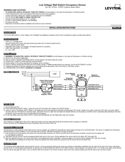
WARNINGS AND CAUTIONS• TO AVOID FIRE, SHOCK, OR DEATH: TURN OFF POWER at circuit breaker or fuse and test that power is off before wiring!• To be installed and/or used in accordance with electrical codes and regulations.• Confirm that device ratings are suitable for application prior to installation.• Use this device with copper or copper clad wire only .• Connect to field wiring rated for 60° C or greater.• DO NOT install if product appears to be damaged.• For indoor use only.•Read these instructions before installation and retain for future reference.The OSS24 Wall Switch is a low voltage (24V) intelligent self-adapting occupancy sensor that is designed to replace existing wall switches.DESCRIPTION• 1000 sq. ft. coverage area• Passive Infrared (PIR) sensor with dual-element pyrometer and 12-element cylindrical lens • 24VDC (requires power pack)• Adjustable Time Delay: 4-30 minutes; self-adjusts based on occupancy • Light Level Adjustment: 10 to 500FC •UL, cUL ListedSPECIFICATIONSINSTALLATION1.WARNING: TO AVOID FIRE, SHOCK, OR DEATH: TURN OFF POWER at circuit breaker or fuse and test that power is off before wiring!2.Remove the old switch if applicable.3.Wire as shown in WIRING DIAGRAM. NOTE: OSS24 requires one power pack per output.4.Install sensor in wall box using mounting screws provided.5.Restore power to the sensor and allow it to initialize (up to 2 minutes).6.Sensor is factory configured to provide the most energy savings. If additional adjustments are required, see the ADJUSTMENTS section.7.If daylight harvesting is desired, calibrate the sensor’s photocell as described in the PHOTOCELL CONTROL section.8.Install wall plate (not included). Installation is complete .TEST MODE1.Ensure lights are ON.2.Press and hold the ON/OFF button. Lights will cycle OFF then back ON. Release the ON/OFF button.3.Sensor is now in Test Mode (NOTE: While in Test Mode the sensor will operate in Automatic ON/Automatic OFF mode). Vacate room; lights should turn OFF after 5 seconds. Wait 5 seconds after turn OFF before re-entering space. Step back into room, lights will turn back ON. Repeat walk test as necessary to confirm sensor is operating and detecting in the area as desired. Sensor will flash red LED when detecting occupancy.4.To exit Test Mode, press any button (NOTE: Sensor will automatically exit Test Mode after sixty (60) minutes).MANUAL OVERRIDEPress button(s) to toggle lights ON or OFF. Lights will remain in the last state determined by the buttons while occupancy is detected.Sensor will return to the programmed mode of operation when the sensor times out.ADJUSTMENTSThe following switch adjustments require that the sensor’s cover be removed. Remove the cover by inserting a small blade screwdriver into the catch at the top of the sensor and gently pry the cover off. Set the adjustment switches as desired (see CONFIGURATION SWITCH SETTINGS section). Factory default is all switches OFF. To re-install cover, place cover directly over the sensor and align the cover’s four (4) catches with the recesses in the sensor housing. Snap cover onto housing making sure that all catches are securely in place.PHOTOCELL CONTROLThe photocell is used to detect if other light sources such as sunlight, are sufficient to illuminate the space without turning on the controlled lights. The sensor is shipped from the factory with the photocell control disabled. If use of the photocell is desired, calibrate the photocell set point as follows:1.With the light level at the desired level where the controlled lights should be off, PRESS and RELEASE the photocell set button using the end of a paper clip or small bladed screwdriver.2.Step back from the sensor to avoid changing ambient light levels in the room. During calibration the sensor will turn the lights OFF then back ON.3.After the calibration process, the sensor will return to its programmed mode of operation. During occupancy, the sensor will turn lighting OFF sixty (60) seconds after reaching or exceeding the set point level. When the lighting level drops below the set point level the sensor will turn the lights ON.DI-000-OSS24-05ALow Voltage Wall Switch Occupancy SensorCat. No. OSS24 - 24VDC (requires power pack)WIRING DIAGRAMGround Neutral LineDI-000-OSS24-05A© 2016 Leviton Mfg. Co., Inc.Switch 1 - Relay 1 Sensor OperationPrograms the sensor for either Manual ON/Automatic OFF operation or Automatic ON/Automatic OFF operation. When set to Manual ON/Automatic OFF mode, lights are turned ON by manually pressing the ON/OFF button. If the sensor times out and turns the lights OFF in the Manual ON/Automatic OFF mode while the space is still occupied, any motion detected within thirty (30) seconds will automatically turn the lights back ON, without requiring the user to press the ON button.Switch 2 - NOTE: Switch 2 has no function on single relay models.Switch 3 - Adaptive or Fixed TimerControls selection between Adaptive Timer Mode and Fixed Timer Mode. In Adaptive Timer Mode, the sensor automatically self-adjusts its timeout delay to optimize energy savings. The sensor will initialize its timer value to eight (8) minutes. If the Bank B Timer Select 0 and Timer Select 1 switches have been set to four (4) minutes, this will be the smallest timer value used. In Fixed Timer Mode, the sensor’s self-adapting timer functions are disabled and the sensor’s timeout delay is set according to the Bank B Timer Select 0 and Timer Select 1 switch settings.Switch 4 - Adaptive ResetThe sensor is equipped with self-adaptive technology which automatically adjusts the sensor’s sensitivity and timer settings to optimize performance based on occupancy patterns. The sensor constantly learns and adjusts appropriately. If the learned settings need to be reset (e.g. when relocating sensor to another area), toggle the switch ON then OFF. The adaptive timer is reset according to the Bank B Timer Select 0 and Timer Select 1 switches. The adaptive sensitivity is reset to factory default. The photocell sensor settings are also reset to factory default (disabled) such that the sensor will turn on the light(s) in response to occupancy regardless of ambient light levels in the lighted space. (NOTE: Adaptive reset can also be achieved by pressing and holding the photocell set button for ten (10) seconds).Switch 5 – Relay BypassIf it is necessary to service the controlled circuits without de-energizing them at the breaker panel (NOTE: this is not recommended as a standard procedure), perform the following steps:1. With the lights ON, set the relay bypass switch to the ON position.2. Push the button(s) to turn the lights OFF.3. Push the button(s) again to verify override (lights should not come back on).The relay bypass switch will now interrupt sensor operation, preventing output(s) from turning ON again, regardless of occupancy or pushbutton conditions. To return the sensor to normal operation, flip the relay bypass switch to the OFF position. To confirm sensor is operating normally, lights should now turn ON and OFF when the button(s) are pressed.Switches 1 and 2 – Timer SettingsSets the length of time lights will remain ON after last motion is detected. The timeout value can be set to 4, 8, 16 or 30 minutes.See Bank A – Switch 3 - Adaptive or Fixed Timer section for additional information.Switches 3 and 4 - Sensing Technology Enable/DisableEnables or disables the occupancy sensing technologies used by the sensor. If all sensing technologies are disabled, sensor operates as a manual ON/OFF switch.Switch 5 - SensitivitySets the sensor’s initial Passive Infrared (PIR) sensitivity level. Sensitivity can be set to either High or Low.For Technical Assistance Call: 1-800-824-3005 (U.S.A. Only) LIMITED 5 YEAR WARRANTY AND EXCLUSIONSLeviton warrants to the original consumer purchaser and not for the benefit of anyone else that this product at the time of its sale by Leviton is free of defects in materials and workmanship under normal and proper use for five years from the purchase date. Leviton’s only obligation is to correct such defects by repair or replacement, at its option. For details visit or call 1-800-824-3005. This warranty excludes and there is disclaimed liability for labor for removal of this product or reinstallation. This warranty is void if this product is installed improperly or in an improper environment, overloaded, misused, opened, abused, or altered in any manner, or is not used under normal operating conditions or not in accordance with any labels or instructions. There are no other or implied warranties of any kind, including merchantability and fitness for a particular purpose , but if any implied warranty is required by the applicable jurisdiction, the duration of any such implied warranty, including merchantability and fitness for a particular purpose, is limited to five years. Leviton is not liable for incidental, indirect, special, or consequential damages, including without limitation, damage to, or loss of use of, any equipment, lost sales or profits or delay or failure to perform this warranty obligation . The remedies provided herein are the exclusive remedies under this warranty, whether based on contract, tort or otherwise.FOR CANADA ONLYFor warranty information and/or product returns, residents of Canada should contact Leviton in writing at Leviton Manufacturing of Canada Ltd to the attention of the Quality Assurance Department, 165 Hymus Blvd, Pointe-Claire (Quebec), Canada H9R 1E9 or by telephone at 1 800 405-5320.* Only functional on multi-tech models.。
交通科技与管理13智慧交通与信息技术1 背景1.1 客运大巴的作用客运大巴除了可以满足绝大多数“市到市”的出行需求以外,还可以满足“市到县”、“县到县”的出行需求。
1.2 客运大巴的市场2018年我国公路客运量为136.72亿人次,铁路客运量为33.75亿人次[1],公路客运量是铁路客运量的4倍,客运大巴在我国仍有较大的市场。
1.3 大中型客车保有量目前我国大中型客车保有量共计232万辆,可见客车的数量十分庞大。
1.4 客车运营商管理要素客车运营商的管理困难主要分为人(驾驶员)、车、线路三个方面。
2 介绍G-BOSG-BOS 集成智能化、电子化、信息化等,以数据挖掘、无线物联与远程控制为核心,为客车运营商量身定制的新一代智能运营管理工具[2]。
3 G-BOS 应用的主要技术3.1 G-BOS 终端G-BOS 终端主要功能为:车载电脑、行车记录仪、GPS 定位仪、发动机故障报警器、视频显示器、短消息接收器等。
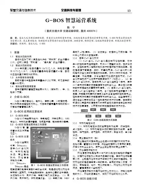
3.2 G-BOS 智慧运营系统工作原理G-BOS 智慧运营系统工作原理见图1。
3.3 G-BOS 主要技术G-BOS 主要技术有:Telematics、客车CAN 总线技术、发动机电控系统、商业智能技术、网络信息传输技术等。
3.3.1 TelematicsTelematics 是远距离通信的电信与信息科学的合成词,就是通过无线网络将车辆接入互联网,为车主提供驾驶、生活所必需的各种信息。
系统架构分为:用户终端、车载终端及系统后台。
(1)用户终端:用户手机、移动便携设备。
(2)车载终端:MRN导航及ATB 模块。
(3)系统后台:数据中心及服务器、呼叫中心及服务内容提供商。
3.3.2 客车CAN 总线技术(1)CAN 总线。
CAN 总线是区域网络控制器,它将单一的控制单元连接起来,形成一个完整的系统。
在该系统中,各控制单元以相同的规则进行数据传输交换和共享。
在数据通信方面高速、实时、可靠和灵活。


网络多功能电力仪表(LED版)使用手册(2012.05.V2.0版)目录一、概述 (1)二、技术参数 (1)2.1辅助电源 (2)2.2输入信号 (2)三、编程和使用 (2)3.1按键定义 (2)3.2测量显示…………………………………………………………………2-33.3 页面显示示意图……………………………………………………………………3-73.4编程操作 (8)3.5菜单组织结构图 (9)3.6编程菜单结构图 (10)调试举例图…………………………………………………………………………11-14四、数字通讯 (15)4.1 报文格式指令………………………………………………………………16-194.2脉冲输出 (20)4 .3 开关量输入 (20)4 .4开关量输出 (21)开关量输出对照表 (22)4. 5变送输出 (23)变送输出对照表……………………………………………………………………24-25 M O D B U S-R T U通讯地址信息表………………………………………………26-31五、接线图 (32)42 方型接线图 (32)96方型接线图 (33)80方型接线图 (34)六、常见问题及解决方案 (35)网络多功能电力仪表--用户手册一、概述网络多功能电力仪表是一种具有可编程测量、显示、数字通讯和电能脉冲变送输出等功能的网络多功能电力仪表,能够完成电量测量、电能计量、数据显示、采集及传输,可广泛应用变电站自动化,配电自动化、智能建筑、企业内部的电能测量、管理、考核。
测量精度2.1 辅助电源:网络多功能电力仪表具备通用的(AC/DC)电源输入接口,若不作特殊声明,提供的是AC/DC85~270V电源接口的标准产品,请保证所提供的电源适用于该系列的产品,以防止损坏产品。
注:采用交流供电时,建议在火线一侧安装1A保险丝。
电力品质较差时,建议在电源回路安装浪涌抑制器防止雷击,以及快速脉冲群抑制器。

第4章任务管理 (1)4.0建立任务,OSTaskCreate() (2)4.1建立任务,OSTaskCreateExt() (6)4.2任务堆栈 (9)4.3堆栈检验,OSTaskStkChk() (11)4.4删除任务,OSTaskDel() (14)4.5请求删除任务,OSTaskDelReq() (17)4.6改变任务的优先级,OSTaskChangePrio() (20)4.7挂起任务,OSTaskSuspend() (23)4.8恢复任务,OSTaskResume() (25)4.9获得有关任务的信息,OSTaskQuery() (26)第4章任务管理在前面的章节中,笔者曾说过任务可以是一个无限的循环,也可以是在一次执行完毕后被删除掉。
这里要注意的是,任务代码并不是被真正的删除了,而只是µC/OS-Ⅱ不再理会该任务代码,所以该任务代码不会再运行。
任务看起来与任何C函数一样,具有一个返回类型和一个参数,只是它从不返回。
任务的返回类型必须被定义成void型。
在本章中所提到的函数可以在OS_TASK文件中找到。
如前所述,任务必须是以下两种结构之一:void YourTask (void *pdata){for (;;) {/* 用户代码 */调用µC/OS-Ⅱ的服务例程之一:OSMboxPend();OSQPend();OSSemPend();OSTaskDel(OS_PRIO_SELF);OSTaskSuspend(OS_PRIO_SELF);OSTimeDly();OSTimeDlyHMSM();/* 用户代码 */}}或void YourTask (void *pdata){/* 用户代码 */OSTaskDel(OS_PRIO_SELF);}本章所讲的内容包括如何在用户的应用程序中建立任务、删除任务、改变任务的优先级、挂起和恢复任务,以及获得有关任务的信息。
µC/OS-Ⅱ可以管理多达64个任务,并从中保留了四个最高优先级和四个最低优先级的任务供自己使用,所以用户可以使用的只有56个任务。
1VG4 AutoDome® 自动监控系列1.1VG4 系列用户手册补遗:安装和更新所需的软件要在 Microsoft® Internet Explorer 中观看来自启用 IP 的 VG4 AutoDome 的实况视频,或者要更改VG4 AutoDome 配置,您必须在此文件夹中安装下列软件:1.Sun® Java2.Microsoft® .NET 2.x3.Microsoft® DirectX 9.0c4.MPEG-ActiveX 4.245.ConfigManager 01.60.0074.0您可以在博世安防系统网站上获得所需软件的最新版本。
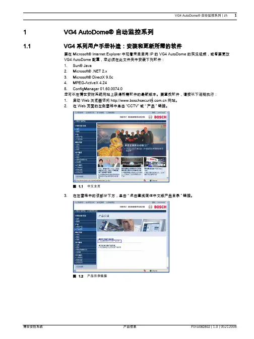
要查找软件,请按以下说明执行:1.启动 Web 浏览器访问 网站。
2.在 Web 页面的左侧窗格中单击“CCTV”或“产品”链接。
图 1.1 中文主页3.在左窗格中的该部分下方,单击“点击查阅简体中文版产品目录”链接。
图 1.2 产品目录链接4.在左窗格中的“下载库”部分下方,单击“软件”链接。
图 1.3 软件链接5.单击“确定”同意遵守“博世软件许可协议”。
图 1.4 博世最终用户许可协议6.在中间框内的“软件”标题下方,单击“闭路监控系统”链接。
图 1.5 主软件框7.单击“自动监控系统”链接访问博世云台摄像机的软件。
图 1.6 云台摄像机链接在单击“云台摄像机”后,浏览器会打开用于 VG4 和 VEZ AutoDomes 的软件下载页面。
图 1.7 VG4 软件下载页面8.向下滚动页面至“AutoDome® TCP/IP 通信模块”部分。
图 1.8 所需的软件9.右键单击“EN 选择”,然后从下列软件包的弹出菜单中选择“目标另存为”:-Sun® Java-Microsoft® .NET 2.x-Microsoft® DirectX 9.0c-MPEG-ActiveX 4.24-ConfigManager 01.60.0074.010.将每个软件包保存到装有 Microsoft Internet Explorer 的计算机。

Ecology安装手册——AIX篇联系人朱巍(Well)Weaver Software上海(总部):中国上海浦东软件园陆家嘴分园101号3层上海(总部)邮政编码:200127华南(深圳):广东省深圳市福田区景田路擎天华庭大厦B座32A华南(深圳)邮政编码:518034电话:+86 755 83144692-808上海泛微网络科技有限公司 1传真:+86 755 83144671文档版本历史上海泛微网络科技有限公司 2目录一、安装准备 (5)1. 本地环境准备 (5)1.1 服务器访问地址 (5)1.2 服务器开放端口 (5)1.3 需使用的工具 (5)2. 检查操作系统 (5)2.1 检查操作系统版本 (5)2.2 检查操作系统字符集 (6)3. 检查SDK是否安装 (6)3.1 根据操作系统版本下载SDK (6)3.2 安装SDK (6)3.3 检查SDK是否安装成功 (7)4. 确认HA划分目录 (7)5. 检查Oracle需使用的包 (8)二、安装Oralce (9)1. 检查Oracle安装所需要的环境参数 (9)1.1 内存 (9)1.2 SWAP (9)1.3 /tmp目录 (9)1.4 Oracle安装目录 (9)1.5 修改limits文件 (9)2. 安装补丁包 (10)2.1 确认补丁是否已打 (10)2.2 下载补丁包文件 (10)2.3 打包安装 (10)3. 准备Oracle安装 (11)3.1 上传文件 (11)3.2 解压gz包 (11)3.3 解压cpio包 (11)3.4 创建用户、组并授权对应目录 (11)3.5 修改oracle用户的环境变量 (12)3.6 root账户的准备 (13)4. 安装Oracle (13)4.1 使用oracle用户登录检查环境变量 (13)4.2 使用GUI安装数据库 (13)4.3 安装数据库实例 (14)4.4 创建数据库监听 (14)4.5 配置Oracle数据库自启动 (14)4.6 AIX下Oracle常用命令 (15)三、安装Ecology产品 (16)1. 上传文件 (16)上海泛微网络科技有限公司 32. 解压文件 (16)3. 配置resin (16)4. 创建用户并授权 (17)5. 完成 (17)上海泛微网络科技有限公司 4一、安装准备1.本地环境准备1.1服务器访问地址确认服务器的访问地址,保证本地与两台小型机之间能够正常访问。

u Fully integrated intrusion and fire, allows users to interface with one system instead of twou Conettix IP‑based communication options provide high‑speed, secure alarm transport and controlthrough connection of wired and/or cellular network interfacesu Up to 4 programmable areas, each supporting both perimeter and interior pointsu40 points with flexible configuration options to meet multiple installation requirementsu Your choice of touch screen, vacuum florescent, ATM style or LED keypadsGV4 panels are the premier commercial control panel line from Bosch. GV4 panels integrate intrusion and fire, providing one simple user interface for all systems. With the ability to adapt to large and small applications, the D7212GV4 provides up to 40 individually identified points that can be split into 4 areas. The control panel includes a communicator that sends events to selected public switched telephone network (PSTN), IP network, or cellular network destinations through four programmable route groups. With the D7212GV4 you can:•Monitor alarm points for intruder or fire alarms while operating keypads and other outputs•Program all system functions local or remote usingRemote Programming Software (RPS) or by usingbasic programming through the keypad userinterface.FunctionsProgrammable Outputs• 2 A alarm power at 12 VDC• 1.4 A auxiliary power at 12 VDC•Four alarm‑output patterns•Programmable bell test System Response•High-performance micro‑controller providesindustry‑leading system response•High-speed device bus (NEW)•31 custom point indexes, including fire supervisory •Selectable point response time•Cross point capability•Fire alarm verification•Fire inspector’s local test•Watch mode•Scheduled events (SKEDs) arm, disarm, bypass andunbypass points, control relays, and control authority levelsUser Interface•Supervision of up to 8 keypads (up to 32unsupervised keypads can be used)•Remote Programming Software (RPS) Lite allows end users to perform control panel management tasks –Add/Delete/Change users and authorities, view, and print the panel history event log•Custom keypad text is fully programmable, including remote programming•Full function command menu including CustomFunctions•Authority by area and 16‑character name for eachuser•14 custom authority levels control user’s authority to change, add, or delete passcodes; to disarm orbypass points; and to start system testsArea ConfigurationsArea programming offers a wide selection of different system configurations. Each area is assigned an account number to define annunciation, control, and reporting functions. Multiple areas can be linked to a shared area which is automatically controlled (hallway or lobby). Area arming can be conditional on other areas (master or associate). Any area can be configured for perimeter and interior arming, not requiring a separate area for this function.Custom FunctionsFor added convenience, Custom Functions can be programmed to eliminate keystrokes for users allowing the installer to program an easy command for a complicate function. For example, a custom function can be written to bypass a group of points and arm the system, allowing the user to perform this function with one easy command. These Custom Functions can be activated from a keypad, or automatically as a scheduled event (SKED), providing further flexibility and ease of use.Passcode SecurityFor high security applications, GV4 can be configured for several different passcode options.•Two-Man Rule - Requires two people with two unique passcodes to be present at the time of opening.•Early Ambush - Allows users to verify that the facilityis safe by requiring two passcode entries at the same keypad, sending a duress event if the user does notenter the passcode a second time after inspecting the premises.Easy Exit ControlThe D7212GV4 Control Panel changes from one armed state to another armed state without disarming. For example, if you change the state from Perimeter Arm to Master Arm, the control panel complies and reports the change. Easy Exit Control reduces the number of keystrokes, simplifying system operation. Programmable Passcode‑controlled Menu ListThe system prompts users to enter a passcode prior to viewing the keypad menu. The keypad display shows the user the menu options allowed according to the user’s authority level. Passcode-controlled menus provide users only with the options and information pertinent to them, simplifying system operation. Flexible ControlThe system provides the flexibility to select added convenience or high security. For example, you can restrict passcode arming and disarming to a keypad's immediate local area, even if the user has access to other areas. This is particularly useful for high security areas, where a user may have access to the area, but would prefer to only disarm the area individually rather than with the rest of the system. Another option is to program the system to disarm all areas the user can access from any keypad.Invisible Walk TestA menu item allows the user to test invisible 24‑hour points within the scope of the keypad without sending a report to the central station.System UsersThe system supports up to 99 users, each can have a passcode, and a wireless keyfob (NEW). User passcodes contain three to six digits. Passcodes can be assigned to one of 14 customized authority levels in each area and can be restricted to operate only during certain times.Communication FormatsThe D7212GV4 Control Panel prioritizes and sends reports in Contact ID or Modem IIIa2 communications formats to four route groups. Each group has a programmable primary and backup destination.The D7212GV4 provides flexible communications for most central stations with reporting capabilities such as:•Individual point numbers•Opening or closing reports by user and area number •Remote programming attempts•Diagnostic reportsIP CommunicationThe D7212GV4 uses the B420 Ethernet Communication Module (NEW), DX4020 Ethernet Communicator, and/or the ITS‑DX4020‑G Cellular Communicator to communicate with the ConettixD6600 and D6100i Communications Receiver/ Gateways. Using Conettix IP communication offers a secure path that includes anti-replay/anti-substitution features and provides enhanced security with encryption. The B420, DX4020 and ITS‑DX4020‑G can all be used for remote programming.GV4 is the first Security Control panel to support DNS (Domain Name System) for both remote programming and central station communication. DNS provides ease of use, eliminating the need to use static IP addresses as your reporting destination, and accommodates a simple solution for central station disaster recovery. IP Setup is available via the installer keypad menus and the remote programming software, eliminating the need to use complicated internet programming tools such as ARP and Telnet (NEW).Communication PathsD7212GV4 Control Panels accommodate up to four separate destinations for primary, alternate, and backup receivers for automatic test reports.When resetting alarms or arming or disarming a system, the user is identified by name and number.Firmware Updates (NEW)Remote firmware updates using the RPS Firmware Update wizard through the IP connection (B420 Ethernet Communication Module) as well as an on-site flash update key, provides for easy feature enhancements without replacing ROM chips.A wide variety of input optionsEach point:•Accommodates normally‑open (NO) andnormally‑closed (NC) devices with end‑of‑line (EOL)resistor supervision.•Is programmable for fire, fire supervisory, or intrusion application.•Can be hard-wired, addressable, or wireless. Security and Fire DetectionThe D7212GV4 Control Panel provides eight on‑board points, and up to 32 additional off‑board points. You can program individual points to monitor all types of burglar alarms, fire alarms, and supervision devices. Wireless Interface (New)The B820 SDI2 Inovonics Interface Module connects an Inovonics EN4200 Serial Receiver to the control panel SDI2 bus, allowing this UL Listed (NEW) wireless system to be programmed locally via the panel keypad, as well as remotely through RPS. Event LogThe event log stores up to 1,000 local and transmitted events. The event log includes time, date, event, area, point, user number, and transmission status (NEW). View the event log from a keypad or use RPS to remotely retrieve event information. RPS operators can retrieve events periodically using one call, rather than receiving several calls each day. When the event log reaches a programmed threshold of stored events, it can send an optional report to a receiver. Scheduled Events (SKEDs)The internal clock and calendar start individually scheduled events (SKEDs). SKEDs perform functions such as arm or disarm, relay control, or point bypassing. The D7212GV4 Control Panel offers:•40 scheduled events with up to 25 different functions •Eight opening windows and eight closing windows •Eight user windows•Day-of-week, date-of-month, or holiday only schedules •Four holiday schedules of 366 days each (leap year) Fire TestWhen a user activates Fire Test Mode, the control panel suppresses all reports to the central station. The keypad and annunciator show all testing data. An automatic sensor reset feature saves time; you do not need to reset the sensors manually. At the end of test, the keypad shows the number of untested points. Programming, Diagnostics and ControlsInstallers can program locally or remotely through RPS as well as basic keypad programming. A programmable system passcode prevents unauthorized remote programming.Two Data Buses (NEW)GV4 provides 2 data buses which support a wide array of components. The SDI bus supports keypads access and communications modules and also allows connection of existing components in a retrofit application. The SDI2 bus (NEW) supports new input and output devices, as well as a new wireless interface module, and an Ethernet communicator. SDI2 allows these devices to be mounted up to 1000 ft (305 m) from the control panel, providing installation convenience and flexibility.USA:UL 365Police Station Connected Burglar Alarm Unitsand SystemsUL 609Local Burglar Alarm Units and SystemsUL 636Holdup Alarm Units and SystemsUL 985Household Fire Warning System UnitsUL 1023Household Burglar Alarm System UnitsUL 1076Proprietary Burglar Alarm Units and Systems UL 1610Central Station Burglar Alarm UnitsANSI/SIACP-01:2010False Alarm ReductionCSFM California Office of The State Fire Marshall FCC Part 15 Class BInstallation/configuration notesCompatible ProductsKeypadsD1265 Touch Screen KeypadD1255 Series Keypads(D1255, D1255W, D1255B, D1255RB, D1265)D1260 Series Keypads(D1260, D1260W, D1260R, D1260BLK, D1260B)D1256RB Fire KeypadD1257RB Remote Fire Alarm AnnunciatorD720 Series Keypads(D720, D720W, D720R, D720B)D279A Independent Zone ControlDetectorsD278S Four‑wire Addressable Detector Base, 12 VDCD285/TH Photoelectric Smoke Detector HeadsD298S Addressable Detector Base, 24 VDCD7050 Series Addressable Photoelectric Smoke and Smoke Heat Detector HeadsF220‑B6PM/S 12/24 VDC Addressable Detector Bases with POPITs FCC 380 Carbon Monoxide DetectorMX775i Addressable PIR DetectorMX794i Long Range Multiplex PIR DetectorMX934i Addressable PIR DetectorMX938i Addressable PIR DetectorZX776Z PIR DetectorZX794Z Long Range PIR DetectorZX835 TriTech Microwave/PIR DetectorZX935Z PIR DetectorZX938Z PIR DetectorZX970 PIR/Microwave DetectorBosch conventional detectors, including Professional Series, Blue Line Gen2, Blue Line, Classic Line, Commercial Line, and Ceiling Mount motion detectors, as well as glass break, seismic, request-to-exit, photoelectric, heat, and smoke detectors.EnclosuresD8103 Universal EnclosureD8108A Attack‑resistant EnclosureD8109 Fire EnclosureMagnetic ContactsBosch magnetic contacts include recessed, terminal connection, miniature, overhead door, and surface mount.ModulesConettix B420 Ethernet Communication Module (NEW) Conettix ITS‑DX4020-G Cellular Integrated Communicator Conettix DX4020 Network Interface ModuleConettix DX4010V2 USB/Serial Interface ModuleConettix C900V2 Dialer Capture ModuleD113 Battery Lead Supervision ModuleD125B Dual Class B Initiating ModuleD127 Reversing Relay ModuleD129 Class A Initiating ModuleD130 Auxiliary Relay ModuleD185 Reverse Polarity Signaling ModuleD192G Notification Appliance Circuit ModuleD5060 MUX ProgrammerB208 Octo-input Module (NEW)B308 Octo-output Module (NEW)B820 SDI2 Inovonics Interface Module (NEW)D8125 POPEX Point ExpanderD8128D OctoPOPIT Eight‑point ExpanderD8125MUX Point ExpanderD8125INV Wireless Interface ModuleD8129 Octo‑relay ModuleD8130 Door Release ModuleD9127 Series POPIT ModulesD9131A Parallel Printer Interface ModuleDS7432 Eight‑input Remote ModuleDS7457i Series Single‑zone Multiplex Input ModulesDS7460i Two‑input ModuleDS7461i Single‑input Multiplex ModuleDS7465i Input and Output ModuleICP-SDI-9114 SDI SplitterProgrammingRPS or RPS‑LITE Remote Programming SoftwareWirelessB820 SDI2 Inovonics Interface ModuleSDI2 Inovonics Interface and Receiver Kit. Includes B820 and EN4200 (ENKIT-SDI2)EN1210 Universal Transmitter (Single-input)EN1210EOL Universal Transmitter with EOL ResistorEN1210W Door-Window Transmitter with Reed SwitchEN1215EOL Universal Transmitter with Wall Tamper, Reed Switch, and EOL ResistorEN1223D Water‑resistant Pendant Transmitter (Double‑button)EN1223S Water‑resistant Pendant Transmitter (Single‑button)EN1224-ON Multiple-Condition Pendant TransmitterEN1233D Necklace Pendant Transmitter (Double-button)EN1233S Necklace Pendant Transmitter (Single-button)EN1235D Beltclip Pendant Transmitter (Double-button)EN1235DF Fixed-location Transmitter (Double-button)EN1235S Beltclip Pendant Transmitter (Single-button)EN1235SF Fixed-location Transmitter (Single-button)EN1247 Glass-break Detector TransmitterEN1249 Bill Trap TransmitterEN1242 Smoke Detector TransmitterEN1260 Wall Mount Motion DetectorEN1261HT High Traffic Motion DetectorEN1262 Motion Detector with Pet ImmunityEM1265 360° Ceiling Mount Motion DetectorEN4200 Serial ReceiverEN5040-T High Power Repeater with TransformerThe D7212GV4 includes the following parts: ponent1D7212GV4 Board1Mounting Skirt1Faceplate with D7212GV4 Label 1Literature pack•Installation Instructions•Owners Manual•Release Notes1Literature CD containing all product literatureThe available kits come with the parts indicated in the following table:Kits Components‑K1‑K1W D7212GV4 Board11 D101F Lock and Key Set11 D1255 Keypad1D1255W Keypad1 D1260 KeypadD1640 Transformer11 D8103 Enclosure11 ISC-BDL2-WP12G TriTech Detector22Kits-K6-K7 D7212GV4 Board11 D101F Lock and Key Set11 D1255 Keypad1 D1255W KeypadD1260 Keypad1D1640 Transformer11 D8103 Enclosure11 ISC-BDL2-WP12G TriTech Detector1 B208 Octo-input Module (NEW)1 Conettix B420 Ethernet CommunicationModule (NEW)1 CommunicationsEnvironmental ConsiderationsNumber of…Power RequirementsTrademarksInovonics is a trademark of Inovonics Wireless Corporation. Ordering informationD7212GV4 40-point Control CommunicatorOrder number D7212GV4D7212GV4-K1 Burglar Kit with D1255Contains one PCB, one lock and key set, one transformer, one universal enclosure, two TriTech motion detectors, and one D1255 Keypad.Order number D7212GV4-K1D7212GV4-K1W Burglar Kit with D1255W Contains one PCB, one lock and key set, one transformer, one universal enclosure, two PIR detectors, and one D1255W Keypad.Order number D7212GV4-K1WD7212GV4-K6 Burglar Kit with D1260Contains one PCB, one lock and key set, one transformer, one universal enclosure, one D1260 Keypad, and one Conettix B420 Ethernet Communication Module (NEW).Order number D7212GV4-K6D7212GV4-K7 Burglar Kit with B208Contains one PCB, one lock and key set, one transformer, one universal enclosure, one D1255 Keypad, one TriTech motion detector, and one B208 Octo-input Module (NEW).Order number D7212GV4-K7AccessoriesSDI2 Inovonics Interface and Receiver KitKit containing B820 and EN4200 for use on SDI2 bus panels.Order number ENKIT-SDI2D101 Lock and Key SetShort-body lock set with one key supplied. Uses theD102 (#1358) replacement key.Order number D101D122 Dual Battery HarnessHarness with circuit breaker. Connects two batteries to a compatible control panel.Order number D122D122L Dual Battery Harness with Long LeadsColor-coded harness with circuit breaker and leads measuring 89 cm (35 in.). Connects 12 V batteries to compatible control panels.Order number D122LD126 Standby Battery (12 V, 7 Ah)A rechargeable sealed lead‑acid power supply used as a secondary power supply or in auxiliary or ancillary functions.Order number D126D1218 Battery (12 V, 18 Ah)A 12 V sealed lead‑acid battery for standby and auxiliary power with two bolt‑fastened terminals. Includes hardware for attaching battery leads or spade connectorsOrder number D1218D1224 Battery (12 V, 26‑28 Ah)A 12 V sealed lead‑acid battery for standby and auxiliary power with two bolt‑fastened terminals. Includes hardware for attaching battery leads or spade connectors.Order number D1224D1238 Battery (12 V, 38 Ah)A 12 V sealed lead-acid battery for standby and auxiliary power with two bolt‑fastened terminals. Includes hardware for attaching battery leads or spade connectors.Order number D1238D137 Mounting BracketUsed to mount accessory modules in D8103, D8108A, and D8109 enclosures.Order number D137D138 Mounting Bracket, Right AngleUsed to mount accessory modules in D8103, D8108A,and D8109 enclosures.Order number D138D1640 TransformerSystem transformer rated at 16.5 VAC, 40 VA.Order number D1640D9002‑5 Mounting Skirt5 pack of mounting skirts for B8103, D8103, D8108A,and D8109 enclosures. Each skirt can hold up to sixstandard 3-hole mounting modules.Order number D9002-5Software OptionsRPS Kit (DVD-ROM and USB Security Block)Account management and control panel programmingsoftware with USB security key (dongle).Order number D5500C-USBRepresented by:Europe, Middle East, Africa:North America:Asia-Pacific:Bosch Security Systems B.V.P.O. Box 800025600 JB Eindhoven, The Netherlands Phone: + 31 40 2577 284****************************** Bosch Security Systems, Inc.130 Perinton ParkwayFairport, New York, 14450, USAPhone: +1 800 289 0096Fax: +1 585 223 9180*******************.comRobert Bosch (SEA) Pte Ltd, Security Systems11 Bishan Street 21Singapore 573943Phone: +65 6571 2808Fax: +65 6571 2699*****************************© Bosch Security Systems 2016 | Data subject to change without notice 2495828491 | en, V14, 21. Jul 2016。

Please read these instructions and warranty information carefully before use and keep them handy for future reference.Online Warranty Registration2-Doors Built-In Refrigerator REF-365U S E R M A N U A LTable of Contents請即進行保用登記﹗有關保用條款細則,請看本說明書最後一頁。
Please register your warranty information now!For Warranty Terms & Conditions,please refer to the last page of this user manual.1.1 WarningsWarning: risk of fire / flammable materials F or EN Standard:This appliance can be used by children aged from 8 years and above and persons with reduced physical, sensory or mental capabilities or lack of experience and knowledge if they have been given supervision or instruction concerning use of the appliance in a safe way and understand the hazards involved. Children shall not play with the appliance. Cleaning and user maintenance shall not be made by children without supervision. Children aged from 3 to 8 years are allowed to load and unload refrigerating appliances. For IEC Standard:This appliance is not intended for use by persons (induding children) with reduced physical, sensory or mental capabilities, or lack of experience and knowledge, unless they have been given supervision or instruction concerning use of the appliance by a person responsible for their safety.Children should be supervised to ensure that they do not play with the appliance.WARNING!• Keep ventilation openings, in the appliance enclosure or in the built-in structure, clear of obstruction.• Do not use mechanical devices or other means to accelerate the defrosting process, other than those recommended by the manufacturer.• Do not damage the refrigerant circuit.• Do not use electrical appliances inside the food storage compartments of the appliance, unless they are of the type recommended by the manufacturer.• Please abandon the refrigerator according to local regulations for it uses flammable blowing gas and refrigerant.• When positioning the appliance, ensure the supply cord is not tapped or damaged.• Do not locate multiple portable socket-outlets or portable power supplies at the rear of the appliance.• Do not use extension cords or ungrounded (two prong) adapters.• DANGER: Risk of child entrapment.Before you throw away your old refrigerator or freezer:Take off the doors. Leave the shelves in place so that children may not easily climb inside.The refrigerator must be disconnected from the source of electrical supply before attempting the installation of the appliance.To avoid contamination of food, please respect the following instructions• Opening the door for long periods can cause a significant increase of the temperature in the compartments of the appliance.• Clean regularly surfaces that can come in contact with food and accessible drainage systems.• Clean water tanks if they have not been used for 48 hours. Flush the water system connected to a water supply if water has not been drawn for 5 days. (note 1)• Store raw meat and fish in suitable containers in the refrigerator, so that it is not in contact with or drip onto other food.• Two-star ** frozen-food compartments are suitable for storing pre-frozen food, storing or making ice-cream and making ice cubes. (note 2)• One * -, two ** - and three-star***) compartments are not suitable for the freezing of fresh food.(note 3)• If the refrigerator is left empty for a long period, switch off, defrost, clean, dry, and leave the door open to prevent mould developing within the appliance.• Note 1, 2.3: Please confirm whether it is applicable according to you product compartment type.This appliance is intended to be used in household and similar applications such as staff kitchen areas in shops, offices and other working environments; farm houses and by clients in hotels, motels and other residential type environments; bed and breakfast type environments; catering and similar non-retail applications.If the supply cord is damaged, it must be replaced by the manufacturer, its service agent or similarly qualified persons in order to avoid hazard.Do not store explosive substances such as aerosol cans with a flammable propellant in this appliance. The appliance has to be unplugged after use and before carrying out user maintenance on the appliance.Refrigerant and Cyclopentane foaming material used for the refrigerator are flammable. Therefore, when the refrigerator is scrapped, it shall be kept away from any fire source and be recycled by a special recycle company with corresponding qualfication other than be disposed by combustion, so as to prevent damage to the environment or any other harm.1.4 Warnings for Using• Do not pull the power cord when pulling the power plug of the refrigerator. Please firmly grasp the plug and pull it out from the socket directly.•To ensure safe use, do not damage the power cord or use the power cord when it is damaged or worn.•Do not arbitrarily disassemble or reconstruct the refrigerator, nor damage the refrigerant circuit; maintenance of the appliance must be conducted by a specialist.•Damaged power cord must be replaced by the manufacturer, its maintenance department or related professionals in order to avoid danger.This manual contains a lot of important safety information which shall be observed by the users.•Please use a dedicated power socket and the power socket shall not be shared with other electrical appliances.The power plug should be firmly contacted with the socket or else fires might be caused.•Please ensure that the grounding electrode of the power socket is equipped with a reliable grounding line.• Please turn off the valve of the leaking gas and then open the doors and windows in case of leakage of gas and other flammable gases.Do not unplug the refrigerator and other electrical appliances considering that anysparks may cause a fire.•Do not use electrical appliances on the top of the appliance unless they are of the type recommended by the manufacturer.•The gaps between refrigerator doors and between doors and refrigerator body are small, be careful not to put your hand in these areas to prevent doors shut on your fingers. Please be gentle when closing the refrigerator door to avoid objects falling.•Do not pick up foods or containers with wet hands in the freezing chamber when the refrigerator is running, especially metal containers in order to avoid frostbite.•Do not allow any children to get into or climb up the refrigerator; otherwise suffocation or falling injury of the child may be caused.• Do not place heavy objects on the top of the refrigerator considering that objects may fall when closing or opening the door, and accidental injuries might be caused.•Please pull out the plug in case of power failure or cleaning. Do not connect the freezer to power supply within five minutes to prevent damages to the compressor due to successive starts.•Do not store beer, beverage or other fluid contained in bottles or enclosed containers in the freezing chamber of the refrigerator; otherwise the bottles or enclosed containers may crack due to freezing to cause damages.1.5 Warnings for Placement• Do not put flammable, explosive, volatile and highly corrosive items in the refrigerator to prevent damages to the product or fire accidents.•Do not place flammable items near the refrigerator to avoid fires.•The refrigerator is intended for household use, such as storage of foods; it shall not be used for other purposes, such as storage of blood, drugs or biological products, etc.1.6 Warnings for Energy• The refrigerator might not operate consistently (possibility of defrosting of contents or temperature becoming too warm in the frozen food compartment) when kept for an extended period of time below the cold end of the range of temperatures for which the refrigerating appliance is designed.• The fact that effervescent drinks should not be stored in food freezer compartments or cabinets or in low-temperature compartments or cabinets, and that some products such as water ices should not be consumed too cold.•The need to not exceed the storage time(s) recommended by the food manufacturers for any kind of food and particularly for commercially quick-frozen food in food-freezer and frozen-food storage compartments or cabinets.• The precautions necessary to prevent an undue rise in the temperature of the frozen food while defrosting the refrigerator, such as wrapping the frozen food in several layers of newspaper.• The fact that a rise in temperature of the frozen food during manual defrosting, maintenance or cleaning could shorten the storage life.•The necessity that, for doors or lids fitted with locks and keys, the keys be kept out of the reach of children and not in the vicinity of the refrigerator, in order to prevent children from being locked inside.1.7 Warnings for DisposalWarnings and RecommendationsCorrect Disposal of this ProductThis marking indicates that this product should not be disposed of with other household wastes throughout the EU. To prevent possible harm to the environment or human health from uncontrolled waste disposal, recycle it responsibly to promote the sustainable reuse of material resources. To return your used device, please use the return and collection systems or contact the retailer where the product was purchased. They can take this product for environmental safe recycling.Refrigerant and cyclopentane foaming material used for the refrigerator are flammable. Therefore, when the refrigerator is scraped, it shall be kept away from any fire source and be recycled by a special recycle company with corresponding qualification other than be disposed by combustion, so as to prevent damage to the environment or any other harm.When the refrigerator is scraped, disassemble the doors, and remove gasket of door and shelves; put the doors and shelves in a proper place, so as to prevent trapping of any child.Product StructureFreezing Chamber• The low temperature freezing chamber may keep food fresh for a long time and it is mainly used to store frozen foods and making ice.• The freezing chamber is suitable for storage of meat, fish and other foods not to be consumed in the short term.• Pieces of meat are preferably be divided into small pieces for easy access.•Please note that the refrigerated food shall be consumed within its shelf life.Refrigerating Chamber• The Refrigerating Chamber is suitable for storage of a variety of fruits, vegetables, beverages and other food consumed in the short term.• Cooked foods shall not be put in the refrigerating chamber until cooled to room temperature.• Foods are recommended to be wrapped up before putting into the refrigerator.•The glass shelves can be adjusted for a reasonable amount of storage space.Note:Storage of too much food during operation ater an initial connection to power may adversely affect the freezing effect of the refrigerator. Foods stored shall not block the air outlet, or otherwise the freezing effect will be adversely affected.2. Adjustable Shelves 4. Bottle Shelves Refrigerating Chamber1. Internal LED Lighting6. Drawer for Frozen Food5. Fruit and Vegetable Box7. Freezer Drawers3. Temperature Control Panel Freezing ChamberPlacementRemove all packing materials, including bottom cushions, foam pads and tapes inside of the refrigerator, tear off the protective film on the doors and the refrigerator body.Check that the appliance is not damaged. The retailer must be informed of any damage to the appliance within 24 hours of delivery.• Keep it away from heat and avoid direct sunlight.• Do not spray or wash the refrigerator; do not put the refrigerator in moist places where it can be splashed with water so as not to affect the electrical insulation properties of the refrigerator.• The refrigerator should be placed in a well-ventilated indoor location; on a flat and sturdy ground.•Check that the mains voltage is the same as that indicated on the rating plate.Dimension of the CabinetWARNING!Please ensure that the refrigerator is well ventilated. Ventilation openings must be provided both at the bottom and the back of the cabinetry to allow for appropriate air flow.WARNING!Precautions before installation: Information in the Instruction Manual is only for reference. The actual product may differ. Before installation and adjusting of accessories, it shall be ensured that the refrigerator is disconnected from power.Unit: mmUnit: mm1. The dimensions of the cabinet must correspond to those specified figures in the diagram.2. Push the refrigerator into the cabinet and adjust it to make sure the edge fold of top baffle completely touch the top edge of the cabinet, and the limit hook ofsupporting leg completely touch the bottom edge of the cabinet.3. Fix the supporting leg with screws and then install the screw caps.Built-in InstallationStepsWARNING!• Do not install it near to sources of heat such as heaters, radiators, cookers, etc. Avoid direct sunlight.• After the appliance has been placed in its final position, leave it for about an hour before connecting the power supply.• Make sure the appliance is working properly before placing any food in it.•Run the refrigerator for 2-3 hours in winter or at least 4 hours in the summer before placing any food in it.4. Fix the top baffle to the top of the cabinet inner with screws and then install the screw caps.7. Take out the sealing strip from accessory bag, and press it in the gap between the cabinet and therefrigerator. Installation is completed.5. Open the lower door of cabinet the maximumangle, and open the lower door of the refrigerator to the corresponding position. Sliding the block to make sure inner edge align with the lower door edge of refrigerator, then fix the block to the door of cabinet with screw and install screw caps.Reversing the Door Opening Direction1. Power off the refrigerator, and remove all objects from the door trays9. Remove the two fixed blocks of freezer door and rotate them for 180°, and install them onother side of freezer door. The picture after completion is shown as above. (The picture above is for reference only. The actual configuration will depend on the actual product or statement by the distributor.)S1. LED Display 8°C S2. LED Display 6°C S3. LED Display 4°C S4. LED Display 2°C Selection ButtonNote:When the fridge is turned on for the first time, the LED lights in the display screen of the temperatureselection zone will be on for 3 seconds and the refrigerator will automatically run at the Temperature of 4°C (S3).FunctionsFault and Non-function IndicationNote: In case of a failure, the corresponding LED light blinks (see below table).Power Off FunctionFirst, press ()for 3 seconds to unlock the selection button, then press () for 10 seconds; when all LED display lights are turned off, the refrigerator will enter the “power off” function mode, all functions will be turned off. All the LED display lights will be off during the “power off” mode.During the power off mode, can short press selection button ()to exit the power off mode and therefrigerator will return to its normal function.• There are 4 temperature selections available with LED Display 8°C, 6°C, 4°C and 2°C. The current temperature setting is indicated when one of the LED lights in the selection zone (S1-S2-S3-S4) is on.• To unlock the current temperature setting, press down and hold the selection button () for 3 seconds, all the LED lights will be blinking for 2 seconds.•Click () to select temperature. The temperature lights of S1-S2-S3-S4 will take turn to be turned on and off and the next one turned on after each click.• The LED light of the selected temperature (S1 to S4) will be turned on permanently. This indicted that the fridge is run on this selected temperature.•If no selection is done in 30 seconds, the selection key () is locked again.Control PanelTemperature SettingCleaning & MaintenanceCleaning & Maintenance• Dusts behind the refrigerator and on the ground shall be cleaned in a timely manner to improve the cooling effect and save energy.• Check the door gasket regularly to make sure there is no debris. Clean the door gasket with a soft cloth dampened with soapy water or diluted detergent.• The interior of the refrigerator should be cleaned regularly to avoid odor.• Please turn off the power before cleaning interior, remove all foods, drinks, shelves, drawers, etc.• Use a soft cloth or sponge to clean the interior of the refrigerator, with two tablespoons of baking soda and a quart of warm water. Then rinse with water and wipe clean. After cleaning, open the door and let it dry naturally before turning on the power.• Please turn off the power and remove all foods before cleaning the interior.• For areas that are difficult to clean in the refrigerator, such as narrow gaps or corners, it is recommended to wipe them regularly with a soft rag or a soft brush, to ensure no contaminants or bacterial accumulation in these areas.• Do not use soap, detergent, scrub powder, spray cleaner for cleaning, as these may cause odors in the interior of the refrigerator or possibly contaminating food.• Clean the bottle frame, shelves and drawers with a soft cloth dampened with soapy water or diluted detergent. Dry with a soft cloth or dry naturally.• Wipe the outer surface of the refrigerator with a soft cloth dampened with soapy water, detergent, etc, and then wipe dry.•Do not use hard brushes, clean steel balls, wire brushes, abrasives (such as toothpastes), organic solvents (such as alcohol, acetone banana oil, etc.) boiling water, acid or alkaline items, which may damage the fridge surface and interior. Boiling water and organic solvents such as benzene may deform or damage plastic parts.• Do not use hard brushes, steel balls, wire brushes for cleaning, which may damage the surface and interior of the fridge.•Do not rinse the fridge directly with water or other liquids during cleaning to avoid short circuits or affecting the electrical insulation after immersion.The refrigerator is made based on the air-cooling principle and thus has automatic defrosting function. Frost formed due to the temperature change or change of season may also be manually removed by disconnecting the appliance from power supply or by wiping with a dry towel.WARNING! Please unplug the refrigerator for defrost and cleaning.3. Out of OperationPower failure: In case of power failure, even if it is in summer, foods inside the appliance canbe kept for several hours. During power failure, refrain from opening the doors and stop putting any food into the appliance.Extended period of non-use: The appliance shall be unplugged and cleaned; leave the doors open to prevent odors forming.Moving: Before moving the refrigerator, take out all objects from inside; fix with tapes all moving parts,such as glass partitions, vegetable holder, freezing chamber drawers etc.; tighten the leveling feet; close the doors and seal them with tapes. During the move, do not lay down the appliance upside down or horizontally. Do not shake or vibrate it and the inclination during movement shall not be more than 45°.WARNING!The appliance shall run continuously once it has been started. Generally, the operation of the appliance shall not be interrupted; otherwise, its service life may be shortened.1. Overll Cleaning2. DefrostingTechnical SpecificationsSpecifications are subject to change without prior notice.If there is any inconsistency or ambiguity between the English version and the Chinese version, the English version shall prevail.Refer to for the most up-to-date version of the Operating Instructions.TroubleshootingYou may try to solve the following simple problems by yourself. If then can not be solved, please contactthe after sales department.注意事項1.1 警告本產品為家用雪櫃,只適用於家庭或類似環境的應用,例如商店、辦公室或工作環境中的廚房區域;亦適用於農舍、酒店、汽車旅館和其他住宅類型環境,或其他非零售性環境。

bpg402说明书BPG 402产品说明书:这款机子是由美国电子工业协会(EIA)提供的安全级别最高的产品之一,它具有独特的防雷功能,能够确保您的电子设备免受雷击。
BPG 402产品是目前国际上公认的最安全的智能无线设备,可以为您提供一个非常安全的电子设备,特别是当您需要远程控制或移动您的智能设备时这是一种非常有用的解决方案。
作为一款高端的产品可以满足您对低功耗、低成本智能设备的需求。
1. BPG 402是一个带有无线网络功能的智能无线控制设备,可以为您提供一个非常安全的电子设备。
同时它的蓝牙无线网络也是采用了先进的射频传输技术,可以使它传输的数据安全可靠。
当我们看到这款机子是一种高性能的无线控制技术,我们看到它是由EIA产品的一个安全级别最高的产品之一,它可以保证我们的任何安全级别。
如果你想将我们的设备插入你的设备并远程控制您的设备的话,您是永远都不会发现不安全的。
BPG 402就如同所有其他智能无线设备一样都采用了防雷接地技术,能够确保您的设备不会受到雷击伤害(特别是当你使用了移动设备的时候)但是由于我们所有设备均具有防雷接地功能(这款机子具备防雷接地功能),所以在您不使用其它电子设备而需要进行操作时BPG 402仍具有一定保护作用。
2. BPG 402可以通过语音和视觉来控制您的智能设备。
它可以通过语音来控制您的手机、电脑、电视和其他智能设备。
语音控制是它强大的功能之一,特别是在语音识别方面BPG 402具有自动识别您设置的所有选项,以允许您通过语音来操作他们。
当您想移动设备时BPG 402会自动发送声音,使其免于打扰您日常生活,同时保持设备处于通话状态。
当您想要对其他设备进行控制时BP G 402可以自动执行您将要移动到其它位置之后再将您的设备重置到您需要控制的位置上。
这不仅有助于您远程控制和移动您的设备,而且还可以节省您电池电量。
3. BPG 402是一个标准的蓝牙网关设备,允许你与任何其他具有相同蓝牙功能或相似功能的无线设备进行通讯。
T o reduce the risk of fire or electric shock, read and follow all instructions and warnings in this manual. Keep this manual for future reference.1. Do not expose this apparatus to rain or moisture. Do not expose this equipment to drippingor splashing, and ensure that no objects filled with liquids, such as vases, are placed on the equipment. Do not use this apparatus near water.2. Do not remove cover. No user serviceable parts inside.3. Clean only with a dry cloth.4. Do not block any ventilation openings. Install according to manufacturer’s instructions.5. Do not install near any heat sources such as radiators, heat registers, stoves or otherapparatus (including amplifiers) that produce heat.6. Do not override the safety purpose of the polarized or grounding plug. A polarized plug hastwo blades, one of which is wider than the other. A grounding plug has two matching blades and a third grounding prong. The wide blade or the third prong is provided for your safety. If the provided plug does not fit into your outlet, consult an electrician for replacement of the obsolete outlet.7. Protect the power cord from being walked on or pinched, particularly at the plug end andwhere the power cord is attached to the apparatus.8. Only use attachments and accessories specified by the manufacturer.9. Refer all servicing to qualified service personnel. Servicing is required when the apparatushas been damaged in any way, such as when the power supply cord or plug is damaged, liquid has been spilled on or objects have fallen into the apparatus, the apparatus hasbeen exposed to rain or moisture, the apparatus does not operate normally, or it has been dropped.10. T o completely disconnect this equipment from power, disconnect the power supply cordfrom the power outlet.The lightning flash with arrowhead symbol, within an equilateral triangle, is intended to alert the user to the presence of uninsulated dangerous voltage within the product’s enclosure that may be of sufficient magnitude to constitute a risk of electric shock to persons.The exclamation point within an equilateral triangle is intended to alert the user to the presence of important operating and maintenance (servicing) instructions in the literature accompanying the appliance.2This equipment has been tested and found to comply with the limits for a Class B digital device, pursuant to Part 15 of the FCC Rules. These limits are designed to provide reasonable protection against harmful interference in a residential installation. This equipment generates uses and can radiate radio frequency energy and, if not installed and used in accordance with the instructions, may cause harmful interference to radio communications. However, thereis no guarantee that interference will not occur in a particular installation. If this equipment does cause harmful interference to radio or television reception, which can be determined by turning the equipment off and on, the user is encouraged to try to correct the interference by one or more of the following measures:• Reorient or relocate the receiving antenna.• Increase the separation between the equipment and receiver.• Connect the equipment into an outlet on a circuit different from that to which the receiver is connected.• Consult the dealer or an experienced radio/TV technician for help.Changes or modifications not expressly approved by the party responsible for compliance could void the user’s authority to operate the equipment.31. Product Overview (5)2. Features (5)3. Package Contents (5)4. Device Layout (6)4.1. B-660-MTRX-4x2 Front Panel (6)4.2. B-660-MTRX-4x2 Rear Panel (7)5. Installation & Wiring (8)5.1. Installation (8)5.2. Wiring (8)6. IR Remote control (10)7. RS-232 Control (10)8. Specifications (11)8.1. Transmission Distance (11)9. Warranty (12)10. Support (12)4The B-660-MTRX-4x2 is a 4K HDR 4x2 HDMI Matrix Switcher and allows up to four Ultra High Definition 4K HDR or 1080p HD inputs to be independently routed to two Ultra HD displays.For HDMI output 1, there is a 3.5mm analog and SPDIF optical audio output allowing audio to be extracted from the HDMI source connected to output 1. For HDMI output 2, there’s a SPDIF optical audio output, which can come from the HDMI output 2 source or the HDMI ARC from the TV. This audio is controlled by a dip slider setting on the unit. Each output port supports independent scaling and can be 4K or 1080P, even if the source is the same. The B-660-MTRX-4x2 features a RS-232 port for third party control system connection and control.2.• Routes four HDMI sources to two 4K HDR Ultra HD displays• HDCP 2.2 compliant• Supports up to 4K Ultra HD and DCI resolutions(4096x2160@60Hz)• Each output supports scaling from 4K to 1080P independently• Analog and digital audio de-embedded from output 1• Digital audio de-embedded from HDMI output 2 or HDMI ARC from TV• Supports 12-bit Deep Color, 3D, Lip Sync and loss-less HD audio formats pass through • Multiple control options, include RS-232, IR and push button controlsNote: If the input source is active, whether display device is connected or not, the audio de-embedding port will output normally.3.• 1 x B-660-MTRX-4x2 Matrix• 1 x DC 5V Power Adapter with US Pins• 1 x IR Remote• 1 x Phoenix Male Connector (3.5 mm, 3 Pins)• 2 x Mounting Brackets (with Screws)• 2 x Drywall Screws• 4 x Rubber Feet• 1 x Power Cord Sticker• 1 x Installation Manual54.1.B-660-MTRX-4x2 Front Panel1. POWER LEDOn: The device is powered on.Off: The device is powered off.2. OUTPUT1 SWITCH BUTTONPress to cycle through the active sources that are connected and available for Output 1.3. OUTPUT1 INPUT (1-4) LEDsOn: The HDMI input is selected and active for Output 1.Off: The HDMI input is not selected nor active for Output 1.4. OUTPUT2 SWITCH BUTTONPress to cycle through the active sources that are connected and available for Output 2.5. OUTPUT2 INPUT (1-4) LEDOn: The HDMI input is selected and active for Output 2.Off: The HDMI input is not selected nor active for Output 2.6. IR SENSORReceives IR from handheld IR Remote, IR Emitter, or IR Flasher.64.2. B-660-MTRX-4x2 Rear Panel1. +5V DCConnect to the provided DC 5V power adapter.2. HDMI IN (1-4)Connect to HDMI sources such as Blu-ray player, Media Player, or PC.3. HDMI OUT1Connect to an HDMI display such as a TV, Flat Panel Display, or Projector.4. SPDIF OUTConnect to audio devices such as AV system for digital de-embedded audio from HDMI OUT1.5. AUDIO OUTConnect to audio device such as Amplifier for analog de-embedded audio from HDMI OUT1.6. HDMI OUT2Connect to an HDMI display such as a TV.7. SPDIF OUTConnect to audio devices such as AV system for digital de-embedded audio output from HDMI OUT2 or ARC audio output from the TV connected to HDMI OUT2.8. DIP SWITCHDe-embedded: SPDIF OUT outputs de-embedded audio from HDMI OUT2 source.ARC: SPDIF OUT outputs the ARC audio from the TV connected to HDMI OUT2.9. RS-232Connect to a control PC or control system for RS232 serial control.75.5.1. InstallationThe B-660-MTRX-4x2 can be placed on a solid and stable surface, installed on a standard equipment rack shelf, or mounted to a wall or distribution box. When installed on a rack shelf, wall, or distribution box we strongly recommend that the included mounting ears be used to secure the device. When installing on a solid surface the use of the mounting ears is optional. Steps to install the switch using the supplied mounting ears:1. Attach the installation bracket to the enclosure using the screws provided in the packageseparately.2. The bracket is attached to the enclosure as shown.3. Repeat steps 1-2 for the other side of the unit.4. Mount the switch on a solid surface, rack shelf, wall, or distribution box with the includedmounting screws by screwing the mounting ears to the surface you are mounting to.5.2. WiringWarnings:• Before beginning any wiring be sure to disconnect the power from all devices in the system.• During wiring gently connect and disconnect the cables.Steps for device wiring:1. Connect HDMI INConnect the HDMI sources (such as PC, Blu-ray player, Apple TV, 4K media player, etc) to the HDMI IN 1-4. Ensure you are using a high-quality HDMI cable capable of supplying the maximum resolution you require2. Connect HDMI OUTConnect the HDMI display device (such as a TV, projector, LED/LCD display or otherdisplay device) to the HDMI OUT. Ensure you are using a high-quality HDMI cable capable of supplying the maximum resolution you require.83. Connect SPDIF OUT and AUDIO OUT• RS232 control: Connect a control PC or control system to RS232 port of the Matrix.• IR control: The IR Remote provided is for controlling the Matrix through IR signal.5. Connect the DC 5V power cord provided.6. Power on all attached devices.9106.The Matrix can be controlled by the IR Remote provided by pointing it directly at the IR sensor on front panel. This allows for selecting inputs (source) for each output (display) as well as power On and Off for connected CEC-enabled displays.Note:• While the battery is installed it is isolated from the internal contacts via a plastic tab. Be sure to remove this tab before operating the remote.• While the remote contains Output 3 and 4 these have no function on this matrix.Display of Output 1Display of Output 1Assigning Inputs (sources) to Outputs (display):1. On the remote locate the output to assign an input to, these are in order vertically from top to bottom labeled in the middle of the remote.2. Press the desired Input # or use thePrevious Next available inputs.Virtual IR Code Supported by Default (Matrix Switching Code)11Advanced users may need to control the matrix through RS232 serial communication.Connect a control PC or control system to the RS232 port of the receiver. API command for RS232 control is available in the separate document “API Command Set_ B-660-MTRX-4x2”. A professional RS232 serial interface software (e.g. Serial Assist) may be needed as well.Before executing the API command through RS232 serial connection, please ensure RS232interface of the device and the control PC are configured correctly.RS-232 Port Connection Pin outR T GN XX D TXRX G RS-232PortConnected RS-232Device PinsTransmission Distance8.1.122-Year Limited WarrantyThis Binary product has a 2-Year limited warranty. This warranty includes parts and labor repairs on all components found to be defective in material or workmanship under normal conditions of use. This warranty shall not apply to products that have been abused, modified or disassembled. Products to be repaired under this warranty must be returned to SnapAV or a designated service center with prior notification and an assigned return authorization number (RA).10.Need Help? Contact T ech Support!If you need further clarification, please call tech support at 800.838.5052, or email support@ . For other information, instructional videos, support documentation, or ideas, visit our website and view your item’s product page at .13Rev: 200331-1719© 2020 Binary。
4/2 servo solenoid valves withon-board electronics (OBE), positive overlap and position feedbackType 4WRPE ..EA..RE 29024/01.051/16Replaces: 05.04Size 6, 10Unit series 2XMaximum working pressure of P, A, B 315 bar, T 250 bar (NG6)Maximum working pressure of P, A, B 315 bar, T 200 bar (NG10)Nominal flow rate 18...32 l/min (NG6), 50...80 l/min (NG10)List of contentsContents PageFeatures1Ordering data and scope of delivery 2Preferred types2Function, sectional diagram, symbols 3 and 4T echnical data5 to 8On-board trigger electronics 9 and 10Characteristic curves 11 to 13Unit dimensions14 and 15Features–Directly operated NG6 and 10 valves with positive overlap,actuated on both sides and position-controlled, symbol E –Control solenoid with on-board electronics (OBE), deadband compensation and gain calibrated at the factory –Electrical connection 6P+PE (standard), signal input:differential amplifier with interface A1 = +10 V (F1 on request)–For subplate attachment, mounting hole configuration NG6 to ISO 4401-03-02-0-94 and NG10 to ISO 4401-05-04-0-94–Plug-in connectors to DIN 43563-AM6, see catalog section RE 08008 (order separately)–Subplates as per catalog section RE 45053 and RE 45055(order separately)Variants on request–For standard applications, such as e.g.¼280 bar in P, A, B, T (NG10 + Y, GGG 50)¼Valve electronics 11P+PE (plug-in connector)Ordering data and scope of deliveryPreferred types (available at short notice)Type 4WRPE6 EA Material No. 4WRPE 6 EA18SJ–2X/G24K0/M0811403129 4WRPE 6 EA32SJ–2X/G24K0/M0811403128Type 4WRPE10 EA Material No. 4WRPE 10 EA50SJ–2X/G24K0/M0811404751 4WRPE 10 EA80SJ–2X/G24K0/M0811404750Function, sectional diagramType 4WRPE 6E ..Control solenoid with position transducer Valve bodySymbolsPosition transducer: A-side..E ..*Testing and service equipment– T est box type VT-PE-TB3, see RE 30065– T est adapter type 6P+PE type VT-PA-2, see RE 30068EN 61000-6-2EN 61000-6-3Function, sectional diagramType 4WRPE 10E ..Control solenoid with position transducer Valve bodyLeakage drain “Y” on request (GGG 50)SymbolsPosition transducer: A-side..E ..*Testing and service equipment– T est box type VT-PE-TB3, see RE 30065– T est adapter type 6P+PE type VT-PA-2, see RE 30068EN 61000-6-2EN 61000-6-3Technical data (type 4WRPE6EA..)GeneralConstruction Spool type valve, directly operatedActuation Proportional solenoid with position control, OBEConnection type Subplate, mounting hole configuration NG6 (ISO 4401-03-02-0-94) Mounting position OptionalAmbient temperature range°C–20…+50Weight kg 3Vibration resistance, test condition Max. 25 g, shaken in 3 dimensions (24 h)Hydraulic (measured with HLP 46, ϑoil= 40°C ±5°C)Pressure fluid Hydraulic oil to DIN 51524 ... 535, other fluids after prior consultation Viscosity range recommended mm2/s20 (100)Viscosity range, max. permitted mm2/s10 (800)Pressure fluid temperature range°C–20...+70Maximum permissible degree of Class 18/16/131)contamination of pressure fluidPurity class to ISO 4406 (c)Direction of flow See symbolNominal flow at l/min1832∆p= 5 bar per notch2)Max. working pressure bar Port P, A, B: 315Max. pressure bar Port T: 250Operating limits See chartLeakage at 100 bar per metering edgeϹ80 cm3/minStatic/DynamicHysteresis%Ϲ0.3Range of inversion%Ͻ0.2Manufacturing tolerance%Ϲ±3Response time 100% signal change msϷ12Response time 110% signal change msϷ7Thermal drift<1% at ∆T= 40°CQ N type l/min1830Calibration (factory setting) ±3%l/min U D–E= 1 V=10.4510.78∆p= 5 bar U D–E= 8 V=1530Conformity EN 61000-6-2EN 61000-6-31)The purity classes stated for the components must be complied with in hydraulic systems.Effective filtration prevents problems and also extends the service life of components.For a selection of filters, see catalog sections RE 50070, RE 50076 and RE 50081.∆p x2)Flow rate at a different ∆p q x= q nom·Ί5Technical data (type 4WRPE10EA..)GeneralConstruction Spool type valve, directly operatedActuation Proportional solenoid with position control, OBEConnection type Subplate, mounting hole configuration NG10 (ISO 4401-05-04-0-94) Mounting position OptionalAmbient temperature range°C–20…+50Weight kg7.1Vibration resistance, test condition Max. 25 g, shaken in 3 dimensions (24 h)Hydraulic (measured with HLP 46, ϑoil= 40°C ±5°C)Pressure fluid Hydraulic oil to DIN 51524 ... 535, other fluids after prior consultation Viscosity range recommended mm2/s20 (100)Viscosity range, max. permitted mm2/s10 (800)Pressure fluid temperature range°C–20...+70Maximum permissible degree of Class 18/16/131)contamination of pressure fluidPurity class to ISO 4406 (c)Direction of flow See symbolNominal flow at l/min5080∆p= 5 bar per notch2)Max. working pressure bar Port P, A, B: 315Max. pressure bar Port T: 200Operating limits See chartLeakage at 100 bar per metering edgeϹ80 cm3/minStatic/DynamicHysteresis%Ϲ0.3Range of inversion%Ͻ0.2Manufacturing tolerance%Ϲ±3Response time 100% signal change msϷ25Response time 110% signal change msϷ10Thermal drift<1% at ∆T= 40°CQ N type l/min5080Calibration (factory setting) ±3%l/min U D–E= 0.6 V=10.1510.34∆p= 5 bar U D–E= 8 V=4070Conformity EN 61000-6-2EN 61000-6-31)The purity classes stated for the components must be complied with in hydraulic systems.Effective filtration prevents problems and also extends the service life of components.For a selection of filters, see catalog sections RE 50070, RE 50076 and RE 50081.∆p x2)Flow rate at a different ∆p q x= q nom·Ί5Technical data (type 4WRPE ..EA..)Electrical, trigger electronics integrated in the valveCyclic duration factor %100Degree of protection IP 65 to DIN 40050 and IEC 14434/5Connection Line socket 6P+PE, DIN 43563Power supply 24V DC nomTerminal A:min. 21V DC/max. 40V DC Terminal B: 0V Ripple max. 2V DCPower consumption NG60Solenoid २/45 mm = 40 VA max.NG10Solenoid २/60 mm = 60 VA max.External fuse2.5 A FInput, “Standard” version A1Differential amplifier, R i = 100 k ΩTerminal D: U E +0.4...+10 V Terminal E:0 VInput, “mA signal” version F1Burden, R sh = 200 ΩTerminal D: I D–E 4...20 mATerminal E: I D–ECurrent loop I D–E feedback Max. differential input voltageD ǞBat 0 VE ǞB·max. 18 V DCTest signal, “Standard” version A1LVDTTerminal F: U Test +0.4...+10V Terminal C:Reference 0 VTest signal, “mA signal” version F1LVDT signal 4 ... 20 mA at external load 200...500 Ωmax.Terminal F: I F–C 4...20mA outputTerminal C: I F–CCurrent loop I F–C feedbackSafety earth conductor and shield See pin assignment (installation conforms to CE)Recommended cableSee pin assignmentup to 20 m 7x 0.75 mm 2up to 40 m 7x 1 mm 2CalibrationCalibrated at the factory, see valve curveVersion A1:StandardVersion F1:mA-SignalConnectionFor electrical data see page 7 and Operating Instructions 1 819 929 083Technical notes for the cableVersion:– Multi-wire cable– Extra-finely stranded wire toVDE 0295, Class 6– Safety earth conductor, green/yellow– Cu braided shieldTypes:– e.g. Ölflex-FD 855 CP(from Lappkabel company)No. of wires:– Determined by type of valve,plug types and signal assignment Cable Ø:– 0.75 mm2up to 20 m length– 1.0 mm2up to 40 m lengthOutside Ø:– 9.4...11.8 mm – Pg11– 12.7...13.5 mm – Pg16ImportantVoltage supply 24 V DC nom,if voltage drops below 18 V DC, rapid shutdown resembling “Enable OFF” takes place internally.In addition, with the “mA signal” version:I D–Eм3mA – valve is activeI D–EϹ2mA – valve is deactivated.Electrical signals emitted via the trigger electronics(e.g. actual values) must not be used to shut down safety-relevant machine functions!(Also see European Standard, “T echnical Safety Requirements for Fluid-Powered Systems and Components – Hydraulics”, EN 982!)On-board trigger electronicsCircuit diagram/pin assignmentVersion A1: U D–E+0,4...+10VSupply U BSupply zeroRef. zero *Setpoint 0...+10 VActual value 0...+10 VSafety earth conductor ƄShield* Do not connect to supply zero!Pin assignment 6P+PEVersion A1: U D–E+0,4...+10 V(R i= 100kΩ)On-board trigger electronics Circuit diagram/pin assignment Version F1: I D–E4...20 mAPin assignment 6P+PEVersion F1: I D–E4...20 mA(R sh= 200kΩ)Characteristic curves type 4WRPE6EA..(measured with HLP 46, ϑoil= 40°C±5°C) Flow rate/Signal function (at ∆p= 5 bar per notch)Q nom= 18 l/minQ nom= 32 l/min1)Factory setting Ϲ±3%2)Version: U E= +0.4...+10V3)Version: I E= 4...20 mA UE2) [V]IE3) [mA]UE2) [V]IE [mA]Characteristic curves type 4WRPE10EA..(measured with HLP 46, ϑoil= 40°C±5°C) Flow rate/Signal function (at ∆p= 5 bar per notch)Q nom= 50 l/minQ nom= 80 l/min1)Factory setting Ϲ±3%2)Version: U E= +0.4...+10V3)Version: I E= 4...20 mAUE2)[V]IE3)[mA]Operating limits (measured with HLP 46, ϑoil = 40°C ±5°C)Type 4WRPE6EA ..Type 4WRPE 10EA..Doubled flow rateUnit dimensions type 4WRPE 6EA..(nominal dimensions in mm)Required surface quality of mating componentMounting hole configuration:NG6 (ISO 4401-03-02-0-94)For subplates, see catalog section RE 450531)Deviates from standard 2)Thread depth:Ferrous metal 1.5 x ØNon-ferrous 2 x ØP A T B F 1F 2F 3F 421.512.521.530.2040.540.5025.915.5 5.115.50–0.7531.7531л81)81)81)81)M52)M52)M52)M52)X YNot included in scope of deliveryX YUnit dimensions type 4WRPE 10EA ..(nominal dimensions in mm)Required surface quality of mating componentMounting hole configuration:NG10 (ISO 4401-05-04-0-94)For subplates, see catalog section RE 450551)Deviates from standard 2)Thread depth:Ferrous metal 1.5 x Ø*Non-ferrous 2 x Ø* (NG10 min. 10.5 mm)P A T B F 1F 2F 3F 4R 2716.7 3.237.305454050.86.321.432.521.400464632.5л10.51)10.51)10.51)10.51)M62)M62)M62)M62)10.51)Not included in scope of deliveryBosch Rexroth AGIndustrial HydraulicsZum Eisengießer 1D-97816 Lohr am Main, Germany T elefon+49(0)9352/18-0T elefax+49(0)9352/18-2358 ***************************** www.boschrexroth.de © Bosch Rexroth AG reserves all rights, including industrial property rights. We reserve all rights of disposal, such as copying and passing on to third parties.The data specified above only serve to describe the product. No statements concerning a certain condition or suitability for a certain application can be derived from our information. The given information does not release the user from the obligation of own judgement and verification. It must be remembered that our products are subject to a natural process of wear and aging.Notes。
BOGEER博格尔YT-***码表使用说明书一、参数设置首先要测量出车轮的周长,测出车轮周长后按住码表●键2秒即可进入参数设置模式,在设置模式中,●键为确定键,▲键为选择或调整键,MODE键为退出键。
按●键2秒进入设置模式后,首先要设置时间:按▲键选择12/24小时制,确定后按●键,然后进入时钟依次按小时、分钟、秒的顺序进行调整,确定后进入(DA)日期设置,按年、月、日进行调整确认,随后进入(TH)摄氏温度/华氏温度的选择,确定后再选择公制(Km)/英制(Mile)单位,然后输入车轮周长(预设为2080MM),确认后进入骑行总里程(ODO)设置,按照个、十、百、千…位输入预设为00000公里/英里,再进入骑车总时间(RAT)设置,以小时为单位输入预设为0000小时,确定后即完成设置并进入自动模式(AUTO)状态。
在设置时如果15秒没有输入或按MODE键将会进入自动模式(AUTO)状态。
二、功能查询1、模式切换码表默认状态为AUTO模式,按DST数据栏和CAL数据栏迴圈切换显示,并附有Auto字样闪烁,连续按MODE键,就会在DST数据栏,ODO数据栏,CAL数据栏,RPM数据栏,AUTO模式数据栏之间进行迴圈显示。
2、数据的查询*当显示DST数据栏时可查询DST(骑车距离),RT(骑车时间),当前时间、SPD(即时速度)。
*当显示ODO数据栏时可查询ODO(累计骑车总距离),RAT(累计骑车总时间),Th(当前温度)、SPD MXS(最高速度)。
*当显示CAL数据栏时可查询CAL(卡路里),TT(行程时间)、DA(当前日期),AVS SPD(平均速度)。
*当显示RPM数据栏时可查询RPM(车轮即时速度),RT(骑车时间)、当前时间,SPD(当前速度)。
三、秒表使用在非设置状态下按●键即可启动秒表(SW),按▲键开始和停止秒表,停止时按●键清零。
在秒表启动时按MODE键可查询各数据栏的即时数据。
注意:在秒表状态下不能进入设置模式。
GV4 panels are the premier commercial control panel line from Bosch.Flexible communications optionsUsing Bosch Conettix communication, GV4 can transmit alarm events in both Bosch ModemIIIa2 and Contact ID formats over telephone, data networks and GSM/GPRS cellular networks to increase security and efficiency. GV4 is the first security control panel to support DNS for remote programming and central station communication. With DNS, IP communication is simple to set up from the installer keypad menu or via RPS.Adaptable to virtually any application requirement GV4 panels are as adaptable as they are powerful. The system can be split into up to 32 areas, each with perimeter and interior arming. To provide ease of use, keypads can be configured to operate all areas, or just a single area. Custom text is remotely programmable on each keypad—reducing costly service calls.Remote programmingRemote programming over IP or cellular minimizes service costs by allowing you to service systems or enable and disable certain functions without traveling to a facility. And, remote firmware updates ensure easy maintenance or feature enhancements as they become available. The panel firmware can also be updated locally using a flash key.Banking / Finance▶Use the early ambush feature for banks where the manager opens alone or Two Person disarm where two people are required to open the branch or critical area ▶Use multiple areas to partition the bank for critical areas like the ATM, vault and office. GV4 can even be programmed to easily allow the branch manager to disarm the branch without disarming other critical areasRetail▶Use POPITs to monitor critical coolers and HVACsystems—reducing a big risk for grocery, big-box retail and convenience stores▶Combine Area Control with access control forarming/disarming critical areas like the pharmacy, cash office, warehouse, overhead doors and to eliminate the need for keys Schools▶Use wireless personal transmitters to allow teachers and administrators to call for help from anywhere on campus ▶Custom functions, SKEDs, can be used to provide easy arming for special events such as concerts, sporting events or community meetings Residential▶Use Inovonics EchoStream to monitor outbuildings, such as the pool shed or garage▶Custom functions provide easy one-button arming configurations, such as Go to bed or Go out to the pool ▶ Late-to-open reports can be used to monitor latch-key kidsRemote Security ControlWith a B420 Ethernet Module, you can operate the GV4 from an iPhone, iPad and iPod Touch. Arm or disarm the system, check system status and control outputs or doors using a hand-held device over the Internet or through a local wireless network.Keypad Models D1255B Signature Style Vacuum Fluorescentdisplay (VFD). Provides complete system control D1260B ATM Style Keypad. Improves ease of use with function buttons for common featuresD1265Bright color LCD graphical display. Simple touch screen menu operation offers greatest ease of use.D720LED keypad for simple commands D1255RB Full Function Fire Keypad with VFD D1256RB Fire Alarm Keypad with VFD D1257RBFire Alarm Annunciator with VFDKeypad models and optionsChoose from the simple LED keypad, a color graphical LCD touch screen or the vacuum florescent or ATM style keypads. Models are also available for fire alarm applications.Point and output expansionHardware and wireless expansion options include Bosch’s 2-wire POPIT, the new B208/B308 Octo-input/output modules and Inovonics EchoStream wireless technology. New expansion modules can be mounted up to 1,000 feet away from the panel for added installation flexibility. Any combination of hardwire, addressable and wirelessexpansion is possible to meet application requirements.Conettix IP CommunicationExpansion Modules D9127U Single Input “POPIT” Point Expander, provides one addressable dry contact inputD9127T D9127 with the addition of a magnetic tamper switch D8125Output expansion Module for addressable points and detectorsB208 / B308SDI2 Octo-input / Octo-output Modules B820SDI2 Inovonics EchoStream Interface Module D8128D Eight Input “OctoPOPIT” Point expander D8129Eight Output “Octorelay” Modulereporting, remote programming and DNS GV4 panels integrate intrusion, fire and access control, providing one simple user interface for all systems. The scalable GV4 panels are available with 40 to 246 points and support for up to 1,000 users for large and small applications.ITS-DX4020-GGSM/GPRS module allows alarm reporting and remote programmingcommunication over digital cellular networks.800.289.0096 | BINPG_GV4_v2010122System Overview。
TOUGHBOOK G2—ACCESSORY AND SERVICE GUIDEEXPANSION PACKS (xPAKs)Top Expansion AreaBarcode Reader xPAK Thermal Camera xPAK Serial Dongle xPAK 2nd USB-A xPAK 2nd LAN xPAK FZ-VBRG211U FZ-VTSG211U FZ-VSRG211U FZ-VUBG211U FZ-VLNG211URear Expansion AreaInsertable SmartCard (CAC) xPAK Contactless SmartCard (CAC) xPAKFZ-VSCG211U FZ-VRFG211UStorage512GB CAGED OPAL SSD FZ-VSDG251211TB CAGED OPAL SSD FZ-VSDG21T21POWERPanasonic Standard BatteryFZ-VZSU1VUPanasonic 4-bay Battery Charger(Available Fall)FZ-VCBG21MPanasonic AC Adapter 100WCF-AA5713A2MLIND Car Charger 120WCF-LNDDC120(Requires CF-LNDBRK120 for vehicle dock mounting)KEYBOARDSPanasonic KeyboardColor-selectable backlit with 4 adjustable levels, touchpad, kickstand/handle FZ-VEKG21LMUSB-C, USB-A, release lever & lock, Kensington lockCompatible with Tablet, 20 Laptop Vehicle Dock, and G2 & 20 Desktop Docks)iKey USB Rubber Keyboard NEMA 4XRed Backlit, touchpad, mounting holesSL-86-911-TP-USB-PWIRELESSAirgain Dual LTE & GPS Antenna KitThreaded Black MountAI-3MDCBL19Airgain Dual LTE & GPS Antenna KitThreaded White MountAI-3MDCWH19VEHICLE DOCKSGamber-Johnson Laptop 2-in-1 Vehicle DockGJ-20LVD0V2 vehicle dock (no pass through)GJ-20LVD2V2 vehicle dock (dual pass through)USB-A (2), Serial, Ethernet, HDMI, VGA, lock (keyed alike).(Requires keyboard. Some items/features on the dock and computer are not compatible — please consult your Panasonic representative for details.)Gamber-Johnson Tablet Vehicle Dock7160-0486-00-P vehicle dock (no pass through) – GJ hole pattern7160-0486-02-P vehicle dock (dual pass through) – GJ hole pattern 7160-0487-00-P vehicle dock (no pass through) – VESA 75 hole pattern 7160-0487-02-P vehicle dock (dual pass through) – VESA 75 hole pattern USB-A (2), Serial, Ethernet, HDMI, VGA, lock (keyed alike)(Some items/features on the dock and computer are not compatible —please consult your Panasonic representative for details.)Havis Laptop 2-in-1 Vehicle DockHA-20LDS0 vehicle dock (no pass through)HA-20LDS2 vehicle dock (dual pass through)USB-A (2), Serial, Ethernet, HDMI, VGA, lock (keyed alike)(Some items/features on the dock and computer are not compatible —please consult your Panasonic representative for details.)Havis Tablet Vehicle DockHA-G1TDS2A vehicle dock (dual pass through)USB-A (2), Serial, Ethernet, HDMI, VGA, lock (keyed alike)(Some items/features on the dock and computer are not compatible —please consult your Panasonic representative for details.)DESKTOP DOCKSPanasonic Laptop Desktop DockCF-VEB201UUSB-A (2), Serial, Ethernet, HDMI, VGA, release lever, Kensington lock, power button (Requires keyboard and is compatible with TOUGHBOOK 20 & G2)Panasonic Tablet Desktop DockFZ-VEBG11AUUSB-A (2), Serial, Ethernet, HDMI, VGA, Kensington lock(Compatible with TOUGHBOOK G1 & G2)Panasonic Tablet Desktop DockFZ-VEBG21UUSB-A (4), Serial, Ethernet, HDMI (2), Kensington lock, power button (Compatible with TOUGHBOOK G2 only)PRINTERSBrother RuggedJet 4230BL Printer Bundle(Includes printer, USB cable & wiring harness)203dpi, up to 5ips, USB or Bluetooth, IP54, 7’ DropBR-RJ42BD2YBrother PocketJet 763 Printer Bundle(Includes printer, USB cable & wiring harness)300dpi, up to 8ppm, USB or BluetoothBR-P J763D1Y14WSTRAPS & CASESPanasonic Rotating Hand Strap (with stylus holder & kickstand) FZ-VSTG21UToughMate BackpackTBCBPK-POTHERPanasonic IP55 Digitizer PenFeaturing 2 buttons (right-click & erase)FZ-VNP026UPanasonic TetherFZ-VNT006UPanasonic Blue Cleaning ClothCF-VNC002UPanasonic Screen ProtectorFZ-VPF38UPROFESSIONAL SERVICESIf you’re a mobile worker in a demanding profession, workdays can be hectic, to say the least. It’s often just you and your mobile computer on the front lines, wherever the job takes you. You need to know that you’ll always have the tools you need to do your job.Thousands of organizations choose Panasonic for their employees who work in unforgiving environments. We’ve been making rock-solid mobile computing products for over 20 years and are constantly pushing rugged computing forward. TOUGHBOOK family of computers boast industry-leading low product-failure rates. So it’s no wonder we’ve become the longest-running rugged computer supplier for the U.S. government, law enforcement, utility, and public safety agencies. But even with the toughest tools, work life can be a bit unpredictable. Make sure your workers can always depend on their TOUGHBOOK devices by augmenting them with Panasonic ProServices — Development, Deployment, and Sustainment services that support and augment your IT and field staffs to speed deployments and improve performance of you Panasonic technology investments.Our Standard Warranty protects your TOUGHBOOK computers from manufacturing defects for three years and includes overnight shipping costs to and from our Service Center, as well as priority parts exchange program and repair service at no cost. It provides lifetime access to our U.S.-based technical support hotline (which has average hold times less than 1 minute); online access to drivers, first-aid disks, BIOS updates, tools, utilities, and manuals; free overnight delivery of customer replaceable parts and repaired units (85% of repairs are completed within just 48 hours); and access to Panasonic field service personnel.For those customers who’s environmental conditions require a higher level of accidental damage coverage, Panasonic offers our Ultimate Care warranty program. This “No-Fault” warranty coverage means just that — You break it and we fix it.Panasonic recognizes that one size does not fit all and each customer has a unique set of skills and needs. As such, Panasonic ProServices can offer each customer the right solution to best suit their particular situation. Here are some of the most popular items, but please contact your Panasonic representative or go to the ProServices website for more services and information.DEPLOYMENT BUNDLES48 Hr. Burn-in, Imaging, Asset Tagging, Shipping, Deployment Report, Disk Image Management (Image Management not included in Bronze).APOS: After Point of SaleBRONZE Package: Includes installation of battery/tether/stylus/supplied asset tags, logo badges (purchased separately), and cases or holders which ship in the TOUGHBOOK OEM packaging. Customer image validation, loading of customer image, application of service updates and engineering changes, inclusion of customer documentation and custom box labels, and application of customer BIOS/CMOS settings and single location ground shipping with deployment reporting.PREMIER Package: Includes all the above deliverables, as well as post image configuration services (5 minutes). Over packing for small shipments, expedited deployment, 48 hour burn in, multiple ship to locations, multiple shipping dates, disk image management for the term of the services with multiple image retention and customer portal access. The Panasonic Customer Portal allows for online access to create RMAs and check entitlement status and repair history. • Bronze (One Time)CF-SVCPDBRZ • Premier Deployment 3 YearCF-SVCPDEP3Y • Premier Deployment 4 YearCF-SVCPDEP4Y • Premier Deployment 5 YearCF-SVCPDEP5Y • Premier Deployment APOS 4th YearCF-S09SLCY4AP • Premier Deployment APOS 4 & 5th YearCF-S09SLCY5AP • 3 Month Device Storage CF-SVCPDSSTOR • Kitting with Deployment (up to 4 items) CF-SVCPD K ITTING • Extended Configuration (15 minutes) CF-SVCPDADD • Customer Portal Access CF-SVCCUPORT • OEM Volume License Conversion CF-SVCLICCONV (Converting the MS Windows OEM license allows the application of a client GOLD image at the National Service Center)BIOS CUSTOMIZATIONBIOS settings can be customized to show client logo on bootup or configured to restrict access, enable or disable audio or wireless capabilities as well as restricting media components such as card readers, secure digital flash, fingerprint readers, Bluetooth etc. There is a minimum of 50 units for the BIOS configuration service.• BIOS Custom Splash Screen and/or Configuration CF-SVCBIOS1ULTIMATE CARE PROGRAMThis coverage provides truly comprehensive coverage for out of warranty repairs. That’s right, no cap and no outof warranty billing for accidental damage for the term of coverage. Even items like intentional damage, fire, flood, hurricane, tornado, loss and theft (reported) are covered up to 2% of the deployment.• Ultimate Care 3 Year FZ-SVCTPUCNF3Y• Ultimate Care 4 Year FZ-SVCTPUCNF4Y• Ultimate Care 5 Year FZ-SVCTPUCNF5Y• Ultimate Care 3 Year (DOD Specific) FZ-SVCTPUCDOD3Y• Ultimate Care 4 Year (DOD Specific) FZ-SVCTPUCDOD4Y• Ultimate Care 5 Year (DOD Specific) FZ-SVCTPUCDOD5Y• APOS Ultimate Care 4th Year FZ-SVCTPUCAPOSY4• APOS Ultimate Care 5th Year FZ-SVCTPUCAPOSY5• APOS Ultimate Care 4 & 5th Year FZ-SVCTPUCAPOS2YAPOS: After Point of SalePROTECTION PLUSAccidental Damage Coverage. Any unit for which the Panasonic “Protection Plus” warranty has been purchased will receive additional coverage for any failure that occurs due to accidental damage.• Protection Plus 3 Year FZ-SVCTPNF3YR• Protection Plus 4 Year FZ-SVCTPNF4Y• Protection Plus 5 Year FZ-SVCTPNF5Y• Protection Plus 3 Year (DOD Specific) FZ-SVCTPNFDOD3Y• Protection Plus 4 Year (DOD Specific) FZ-SVCTPNFDOD4Y• Protection Plus 5 Year (DOD Specific) FZ-SVCTPNFDOD5Y• APOS Protection Plus 4th Year FZ-SVCTPNFAPOSY4• APOS Protection Plus 5th Year FZ-SVCTPNFAPOSY5• APOS Protection Plus 4 & 5th Year FZ-SVCTPNFAPOS2YAPOS: After Point of SaleEXTENDED WARRANTYIf this coverage is purchased, the serial numbered unit is entitled to the extended manufacturer warranty coverage with the exception of the battery for which a separate coverage program is available. The cost of labor, parts, and overnight shipping are included in the price of the Extended Warranty Program.• Extended Warranty 4th Year FZ-SVCTPEXT1Y• Extended Warranty 4 & 5th Year FZ-SVCTPEXT2Y• APOS Ext. Warranty 4th Year FZ-SVCTPEXTAPOY4• APOS Ext. Warranty 5th Year FZ-SVCTPEXTAPOY5• APOS Ext. Warranty 4 & 5th Year FZ-SVCTPEXTAPO2YAPOS: After Point of SaleSMART BATTERY WARRANTY PROGRAMThe TOUGHBOOK Smart Battery Warranty provides protection against battery degradation for up to 5 years, guaranteeing optimum efficiency beyond the standard 12 month battery warranty. The TOUGHBOOK Smart Battery warranty includes Smart Service Battery Monitoring software which is installed on each entitled device. This unique product, powered by B2M solutions provides a SAAS based portal to view device battery health; and includes automated delivery of a no cost replacement battery when the original battery reaches 50% of it’s initial design capacity. Also available is Panasonic’s full Smart Service solution which provides unique predictive analytics andin-depth device performance details unavailable via traditional EMM platforms; and provides another differentiation point for our TOUGHBOOK products in the marketplace.• Main Battery 3 Year CF-SVCBATSW3Y• Main Battery 4 Year CF-SVCBATSW4Y• Main Battery 5 Year CF-SVCBATSW5YHOT SWAP & HOT SPARE MANAGEMENT SERVICEWithin a Hot Swap program, when a device requires service, Panasonic sends the user a fully functional computer from a reserve of customer- owned computers stored at Panasonic’s National Service Center. The replacement unit is shipped for next business day delivery whenever a user calls Panasonic Technical Support and determines that the computer needs to be serviced. The user removes the hard drive from the original computer and inserts it into the replacement unit, eliminating the need to transfer files or software. The user keeps the replacement computer and ships the original unit to Panasonic. When the original computer is received by Panasonic, it is repaired, re-imaged and put back into the customer’s consigned inventory for future use.Unlike Hot Swap, when Hot Spare is chosen, the original unit sent in for service is returned to the original end user following service and the original spare unit is returned to the customer owned reserve.• Hot Swap 3 Year FZ-SVCTPHS3YR• Hot Swap 4 Year FZ-SVCTPHS4YR• Hot Swap 5 Year FZ-SVCTPHS5YR• Hot Spare 3 Year FZ-SVCTPHSP3YR• Hot Spare 4 Year FZ-SVCTPHSP4YR• Hot Spare 5 Year FZ-SVCTPHSP5YRSSD NO RETURN & USER REPLACEMENTWhen this coverage is purchased, a customer is not required to send a defective drive back to the service center when replaced due to SSD failure.• 512GB SSD — No Return 3 Year FZ-SVC512SSD3Y• 512GB SSD — No Return 4 Year FZ-SVC512SSD4Y• 512GB SSD — No Return 5 Year FZ-SVC512SSD5Y• 512GB SSD — No Return 3 Year (DOD Specific) FZ-SVC512SSD3YT• 512GB SSD — No Return 4 Year (DOD Specific) FZ-SVC512SSD4YT• 512GB SSD — No Return 5 Year (DOD Specific) FZ-SVC512SSD5YT• 1TB SSD — No Return 3 Year FZ-SVC1TBSSD3Y• 1TB SSD — No Return 4 Year FZ-SVC1TBSSD4Y• 1TB SSD — No return 5 Year FZ-SVC1TBSSD5Y• 1TB SSD — No Return 3 Year (DOD Specific) FZ-SVC1TBSSD3YT• 1TB SSD — No Return 4 Year (DOD Specific) FZ-SVC1TBSSD4YT• 1TB SSD — No return 5 Year (DOD Specific) FZ-SVC1TBSSD5YTLIFECYCLE SERVICES & PROJECT MANAGEMENTEngineering services can include services development and all changes through the life of the Panasonic deployment along with ad hoc technical services. The service level is determined at time of purchase.• Field Engineering Support based on needs analysis CF-SVCFES20/40/60/80/100PUBLIC SAFETY BUNDLE EXTENSIONSThe following SKU’s are available to extend the Public Safety 3 year bundles to year 4 or years 4 and 5. These SKU’s must be purchased with the hardware on the same order. If delayed purchase is desired, please utilize the standard APOS SKU’s for Premier Deployment, SSD No Return, and ProPlus Warranty.• 4th year Public Safety Service Bundle CF-SVCPSY4Add on (Year 4 only)• 4th and 5th years Public Safety Service Bundle CF-SVCPSY5Add on (Year 4 & 5 only)。