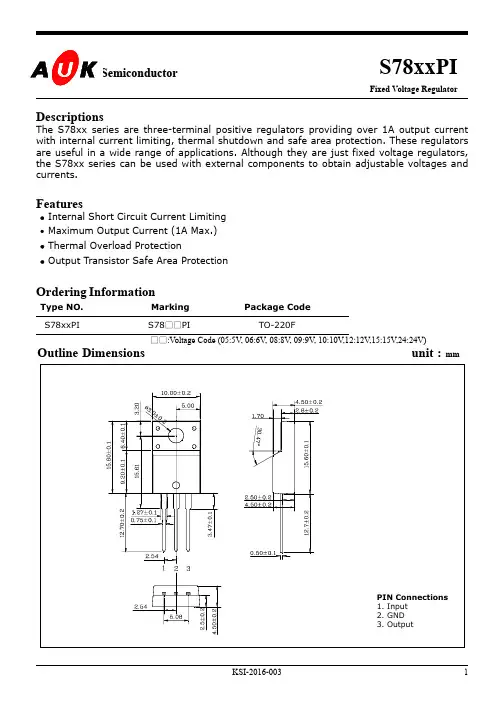
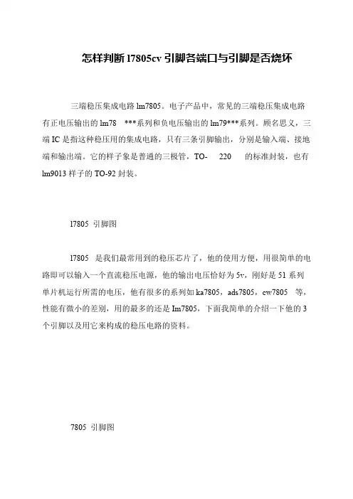
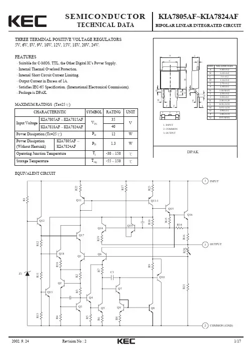
7805pdf
- 格式:pdf
- 大小:228.92 KB
- 文档页数:29
© Semiconductor Components Industries, LLC, 2004
July, 2004 − Rev. 131Publication Order Number:
MC7800/DMC7800, MC7800A,NCV7805
1.0 A Positive Voltage
Regulators
These voltage regulators are monolithic integrated circuits designed
as fixed−voltage regulators for a wide variety of applications
including local, on−card regulation. These regulators employ internal
current limiting, thermal shutdown, and safe−area compensation. With
adequate heatsinking they can deliver output currents in excess of
1.0 A. Although designed primarily as a fixed voltage regulator, these
devices can be used with external components to obtain adjustable
voltages and currents.
•Output Current in Excess of 1.0 A
•No External Components Required
•Internal Thermal Overload Protection
•Internal Short Circuit Current Limiting
•Output Transistor Safe−Area Compensation
•Output Voltage Offered in 2% and 4% Tolerance
•Available in Surface Mount D2PAK−3, DPAK−3 and Standard
3−Lead Transistor Packages
•NCV Prefix for Automotive and Other Applications Requiring Site
and Control Changes
•Pb−Free Packages are Available
MAXIMUM RATINGS (T
A = 25°C, unless otherwise noted)
ValueUnit
RatingSymbol369C221A936
Input Voltage(5.0 − 18 V)
(24 V)V
I35
40Vdc
Power DissipationP
DInternally LimitedW
Thermal Resistance,
Junction−to−AmbientRqJA9265Figure 14°C/W
Thermal Resistance,
Junction−to−CaseRqJC5.05.05.0°C/W
Storage Junction
Temperature RangeT
stg−65 to +150°C
Operating Junction
TemperatureT
J+150°C
Maximum ratings are those values beyond which device damage can occur.
Maximum ratings applied to the device are individual stress limit values (not
normal operating conditions) and are not valid simultaneously. If these limits are
exceeded, device functional operation is not implied, damage may occur and
reliability may be affected.
NOTE:ESD data available upon request.
TO−220−3T SUFFIX
CASE 221A
1
D2PAK−3
D2T SUFFIX
CASE 9362
3
See detailed ordering and shipping information in the package
dimensions section on page 21 of this data sheet.ORDERING INFORMATIONHeatsink surface
connected to Pin 2.
Pin1.Input
2.Ground
3.Output
Heatsink surface (shown as terminal 4 in
case outline drawing) is connected to Pin 2.13
STANDARD APPLICATION
A common ground is required between the
input and the output voltages. The input voltage
must remain typically 2.0 V above the output
voltage even during the low point on the input
ripple voltage.
XX,MC78XXInput
C
in*
0.33 mFC
O**Output
These two digits of the type number
indicate nominal voltage.
C
in is required if regulator is located an
appreciable distance from power supply
filter.
C
O is not needed for stability; however,
it does improve transient response. Values
of less than 0.1 mF could cause instability.*
**
See general marking information in the device marking
section on page 25 of this data sheet.DEVICE MARKING INFORMATIONDPAK−3
DT SUFFIX
CASE 369Chttp://onsemi.com
12
34MC7800, MC7800A, NCV7805
http://onsemi.com
2
R15
680R18
100 k
D1
Zener
R1
10.66 k
R2
1.56 kR17
9.0 kQ7
QNPNLAT
Q17
Q9
QNPN 2
Q8
QNPN
Q14
QNPNQ6
QNPNQ5
QNPN 2LAT 3 A
Q18
R5
4.5 k
R6
1.0 kQ13
QNPN
Q2
QNPN 4SUB
Q11 2R11
15 k
QNPN 6Q1
R7
14 kR3
1.8 kR8
5.0 kDiodeQ16Q4
QNPNN+C1
30 PC2
3.0 PR9
3.0 kR16
600R20
17500Q15
QNPNQ10
QNPN
R22
100
Q12
QNPNR24
50
1.0 P
R21
600R23
0.2R19
27.5 kD2
Zener
Q19
QNPN
R14
1.0 kQ20
QNPN
R28
9.0 k
R27
9.0 kR29
9.0 k
R25
6.0 k
R26
3.0 kR12
3.0 k
R10
3340−(3316ACT)R30
18 k
SenseVout
5.01Vin
R13
11660
Q3
QNPNMC7800
C3
Figure 1. Representative Schematic DiagramThis device contains 22 active transistors.MC7800, MC7800A, NCV7805
http://onsemi.com
3ELECTRICAL CHARACTERISTICS (V
in = 10 V, I
O = 500 mA, T
J = T
low to T
high (Note 1), unless otherwise noted)
MC7805B, NCV7805MC7805C
CharacteristicSymbolMinTypMaxMinTypMaxUnit
Output Voltage (T
J = 25°C)V
O4.85.05.24.85.05.2Vdc
Output Voltage (5.0 mA ≤ I
O ≤ 1.0 A, P
D ≤15 W)
7.0 Vdc ≤ V
in ≤ 20 Vdc
8.0 Vdc ≤ V
in ≤ 20 VdcV
O
−
4.75−
5.0−
5.254.75
−5.0
−5.25
−Vdc
Line Regulation (Note 4)
7.5 Vdc ≤ V
in ≤ 20 Vdc, 1.0 A
8.0 Vdc ≤ V
in ≤ 12 VdcReg
line
−
−5.0
1.3100
50−
−0.5
0.820
10mV
Load Regulation (Note 4)
5.0 mA ≤ I
O ≤ 1.0 A
5.0 mA ≤ I
O ≤ 1.5 A (T
A = 25°C)Reg
load
−
−1.3
0.15100
50−
−1.3
1.325
25mV
Quiescent CurrentI
B−3.28.0−3.26.5mA
Quiescent Current Change
7.0 Vdc ≤ V
in ≤ 25 Vdc
5.0 mA ≤ I
O ≤ 1.0 A (T
A = 25°C)DI
B
−
−−
−−
0.5−
−0.3
0.081.0
0.8mA
Ripple Rejection
8.0 Vdc ≤ V
in ≤ 18 Vdc, f = 120 HzRR−68−6283−dB
Dropout Voltage (I
O = 1.0 A, T
J = 25°C)V
I − V
O−2.0−−2.0−Vdc
Output Noise Voltage (T
A = 25°C)
10 Hz ≤ f ≤ 100 kHzV
n−10−−10−mV/V
O
Output Resistance f = 1.0 kHzr
O−0.9−−0.9−mW
Short Circuit Current Limit (T
A = 25°C)
V
in = 35 VdcI
SC−0.2−−0.6−A
Peak Output Current (T
J = 25°C)I
max−2.2−−2.2−A
Average Temperature Coefficient of Output VoltageTCV
O−−0.3−−−0.3−mV/°C
1.T
low=0°C for MC78XXAC, C, T
high = +125°C for MC78XXAC, NCV7805
=*40°C for MC78XXB, MC78XXAB, NCV7805