DS4025中文资料
- 格式:pdf
- 大小:102.21 KB
- 文档页数:4

产品介绍1.1产品技术参数产品名称网络数字字符叠加器光电式传感器产品型号INV-DS4050楼层显示器传感器专用型电源类型DC12V±10%DC5V(由叠加器供电)功耗<4W<0.5W工作环境温度-40℃至85℃-55℃至120℃工作相对湿度<90%<90%产品尺寸长150mm×宽130mm×高38mm长70mm×宽55mm×高38mm网络接口10M/100M自适应NA报警输出1路NA1.2产品用途介绍适用于各类安装电梯监控的电梯场所,在不改变电梯原有电器线路的情况下,通过光电传感器对电梯运行状态进行采样,能在电视监视器上指示电梯所在楼层数、运行方向、停止及电梯名称。
准确知道电梯当前所在的楼层有利于用户监控的集中管理,对于出入电梯的人员进行监控,或保留录像以备日后查阅,一旦电梯故障,方便维修人员知道电梯所在楼层,从而及时处理,若有事件发生,也可方便的查阅录像中人员在活动的关键层出入情况;有利于事件的解决。
1.3产品性能介绍1、主机可提供一个电平输出作为报警信号;2、传感器在本产品上直接取电,无需再额外为传感器提供电源;3、无需在原有系统中添加交换机等其他设备;4、采用底层协议对接方式,不会对视频画面的清晰度造成任何干扰;5、可叠加电梯名称(汉字,数字,字母,符号均可);6、电梯运行状态指示:上行、下行、楼层号(楼层号显示内容可以通过设置软件任意变换,例如:将地上5层更名为会议室。
)7、安装方便,只需将该设备的光电传感器安装在电梯轿厢顶部原有传感器组的位置,主机放置在轿厢顶部;8、由于支持采用光电传感器对电梯运行状态进行采样,因而采样稳定准确,设备抗干扰性强,可靠性高;9、使用配套软件,在办公室内只需连接PC机、监视器,就能完成对叠加器参数设置;无须现场调试,方便维护;10、可根据需要设置夹层和跳层,确保显示正确,总层数最多支持到100层;1.4物品清单1、电梯字符叠加器一台2、12V电源适配器一个3、电梯专用传感器一个叠加器硬件安装2.1安装示意图下图为电梯井道剖面示意图:2.2光电传感器的安装先将光电传感器固定在电梯的传感器组上,并保证电梯平层时隔磁板能在光电传感器的“U”型口中。
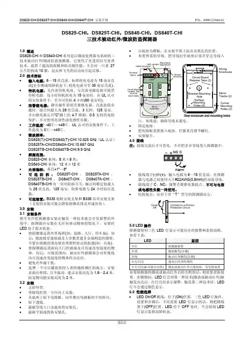
DS825-CHI/DS825T-CHI/DS840-CHI/DS840T-CHI 安装手册 P/N :4998122944-01第1页DS825-CHI ,DS825T-CHI ,DS840-CHI ,DS840T-CHI三技术被动红外/微波防盗探测器1.0 概述DS825-CHI 和DS840-CHI 系列是以微波处理器为基础的三技术被动红外/微波防盗探测器。
它使用了先进的信号处理技术,提供了超高的探测和防误报性能,不会对一只重27公斤的狗或10猫,昆虫和飞鸟的活动而引起误报。
2.0 技术指标 • 输入电源:6—15伏直流,标准耗电电流为15毫安直流(在步测或故障状态下,耗电电流可至35毫安直流)。
• 待机电源:无内部待机电池。
与直流电源连接可提供待机电源。
每小时待机耗电为15毫安时。
在UL 认可的安装条件下,至少可待机4小时(60毫安时)。
• 报警继电器:静音操作常闭舌簧继电器。
直流抗阻负载时,接点间最大为28伏直流,3瓦特,125毫安。
并由继电器公共"C"脚上的4.7欧姆,0.5瓦特的电阻保护。
不可使用电容性或电感性负载。
• 工作温度: -40℃—+49℃。
UL 认可的安装条件下,工作温度为0℃—+49℃。
• 微波频率:DS825(T)-CHI/DS840(T)-CHI:10.525 Ghz (UL 认证) DS825TA-CHI/DS840A-CHI:10.687 Ghz DS825TB-CHI/DS840TB-CHI:9.9 Ghz • 探测范围:DS825-CHI 系列:8米×8米; DS840-CHI 系列:12米×12米 • 内部偏转:垂直+1°—8° • 可选防拆:DS825T-CHI ,DS825TA-CHI ,DS825TB-CHI ,DS840T-CHI ,DS840TA-CHI ,DS840TB-CHI 有一常闭防拆开关。

CANopen笔记3--DS402运动控制⼦协议 DS301就是⼀个通讯协议栈,DS402是建⽴在DS301基础之上的伺服类控制协议。
协议中规定好每个对象字典值的作⽤,⽐如0x6040,是控制字。
DS402把⼀个伺服控制系统应该具有的功能都定义好了,⼚家和使⽤者按照协议定义即可开发和使⽤符合标准的设备。
NMT NMT是⽹络管理报⽂,⽤于实现⼀些管理操作,⽐如节点重启、进⼊运⾏状态等,⽹络管理状态转换图如下: 初始化:设备处于启动状态,不能进⾏通信 预运⾏:设备启动完毕,还未进⼊运⾏模式。
设备仅回复SDO、NMT消息 运⾏:正常⼯作,可回复SDO、NMT、PDO 停⽌:仅能发送NMT(包括⼼跳消息) NMT报⽂格式很简单,COB-ID固定为0x000,数据为:NMT命令 + 从设备节点ID(0x00表⽰⼴播)Boot-up Messages 设备开机启动完成初始化进⼊预运⾏状态时,会产⽣boot-up事件,发送⼀条boot-up消息。
boot-up消息的COB-ID为:0x700 + Node ID。
假设节点ID为1,则该节点开机后会发送boot-up message(0x00 data, always 0)设备控制 根据DS402协议(Chapter 6:Device Control Objects),设备的状态由下图描述。
The device states and possible control sequence of the drive are described by the state machine, as depicted in the following figure: 如上图所⽰,状态机可以分成三部分:“ Power Disabled” (主电关闭)、“ Power Enabled”(主电打开)和“Fault”。
所有状态在发⽣报警后均进⼊“Fault”。
在上电后,驱动器完成初始化,然后进⼊SWITCH_ON_DISABLED状态。
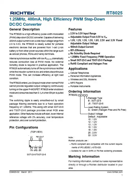
1DS8025-02 March 2011Features2.5V to 5.5V Input RangeAdjustable Output From 0.5V to V IN1.0V, 1.2V, 1.3V, 1.5V, 1.8V,2.5V and3.3V Fixed/Adjustable Output Voltage 400mA Output Current 95% EfficiencyNo Schottky Diode Required1.25MHz Fixed Frequency PWM Operation Small SOT-23-5 and TSOT-23-5 PackageRoHS Compliant and Halogen FreeApplicationsCellular T elephonesPersonal Information Appliances Wireless and DSL Modems MP3 PlayersPortable Instruments1.25MHz, 400mA, High Efficiency PWM Step-Down DC/DC ConverterGeneral DescriptionThe RT8025 is a high-efficiency pulse-width-modulated (PWM) step-down DC/DC converter. Capable of delivering 400mA output current over a wide input voltage range from 2.5 to 5.5V, the RT8025 is ideally suited for portable electronic devices that are powered from 1-cell Li-ion battery or from other power sources within the range such as cellular phones, PDAs and handy-terminals.Internal synchronous rectifier with low R DS(ON) dramatically reduces conduction loss at PWM mode. No external Schottky diode is required in practical application. The RT8025 automatically turns off the synchronous rectifier while the inductor current is low and enters discontinuous PWM mode. This can increase efficiency at light load condition.The RT8025 enters Low-Dropout mode when normal PWM cannot provide regulated output voltage by continuously turning on the upper P-MOSFET . RT8025 enter shutdown mode and consumes less than 0.1μA when EN pin is pulled low.The switching ripple is easily smoothed-out by small package filtering elements due to a fixed operation frequency of 1.25MHz. This along with small SOT-23-5and TSOT-23-5 package provides small PCB area application. Other features include soft start, lower internal reference voltage with 2% accuracy, over temperature protection, and over current protection.Ordering InformationPin Configurations(TOP VIEW)SOT-23-5/TSOT-23-5VIN GND ENNote :Richtek products are :` RoHS compliant and compatible with the current require-ments of IPC/JEDEC J-STD-020.` Suitable for use in SnPb or Pb-free soldering processes.Default : Adjustable 10 : 1.0V 12 : 1.2V 13 : 1.3V 15 : 1.5V 18 : 1.8V 25 : 2.5V 33 : 3.3VMarking InformationFor marking information, contact our sales representative directly or through a Richtek distributor located in your area.2DS8025-02 March 2011 Typical Application Circuit0.5VV and 1M R2R1 with R2R11 x V V REF(Typ.)REF OUT =Ω≤+⎟⎠⎞⎜⎝⎛+=Layout GuideLayout note:1.The distance that C IN connects to V IN is as close as possible (Under 2mm).2. C OUT should be placed near RT8025.Figure 3V OUTV INV OUT3DS8025-02 March 2011Function Block DiagramLXFB/VOUTGND4DS8025-02 March 2011Absolute Maximum Ratings (Note 1)Supply Input Voltage ------------------------------------------------------------------------------------------------------6.5VEnable, FB Voltage -------------------------------------------------------------------------------------------------------V IN + 0.6VPower Dissipation, P D @ T A = 25°CSOT-23-5, TSOT-23-5-----------------------------------------------------------------------------------------------------0.4WPackage Thermal Resistance (Note 2)SOT-23-5, TSOT-23-5, θJA -----------------------------------------------------------------------------------------------250°C/W SOT-23-5, TSOT-23-5, θJC -----------------------------------------------------------------------------------------------130°C/W Junction T emperature Range --------------------------------------------------------------------------------------------150°C Lead Temperature (Soldering, 10 sec.)-------------------------------------------------------------------------------260°CStorage T emperature Range --------------------------------------------------------------------------------------------−65°C to 150°CESD Susceptibility (Note 3)HBM (Human Body Mode)----------------------------------------------------------------------------------------------2kV MM (Machine Mode)------------------------------------------------------------------------------------------------------200VElectrical CharacteristicsRecommended Operating Conditions (Note 4)Supply Input Voltage ------------------------------------------------------------------------------------------------------2.5V to 5.5V Junction T emperature Range --------------------------------------------------------------------------------------------−40°C to 125°CAmbient T emperature Range --------------------------------------------------------------------------------------------−40°C to 85°C5DS8025-02 March 2011Note 1. Stresses listed as the above “Absolute Maximum Ratings ” may cause permanent damage to the device. These are forstress ratings. Functional operation of the device at these or any other conditions beyond those indicated in the operational sections of the specifications is not implied. Exposure to absolute maximum rating conditions for extended periods may remain possibility to affect device reliability.Note 2. θJA is measured in the natural convection at T A = 25°C on a low effective thermal conductivity test board ofJEDEC 51-3 thermal measurement standard.Note 3. Devices are ESD sensitive. Handling precaution recommended.Note 4. The device is not guaranteed to function outside its operating conditions.Note 5. ΔV = I OUT x R DS(ON)_P6DS8025-02 March 2011 Typical Operating CharacteristicsFrequency vs. Temperature1.101.121.141.161.181.201.221.241.26-50-25255075100125Temperature F r e q u e n c y (M H z )(°C)Frequency vs. Input Voltage2.5 2.83.1 3.4 3.744.3 4.6 4.95.2 5.5Input Voltage (V)F r e q u e n c y (M H z )Current Limit vs. Input Voltage2.5 2.83.1 3.4 3.744.3 4.6 4.95.2 5.5Input Voltage (V)C u r r e n t L i m i t (A )Reference vs. Input Voltage2.52.83.13.43.744.34.64.95.25.5Input Voltage (V)R e f e r e n c e (V )Efficiency vs. Load Current1020304050607080901000.010.110.210.310.410.510.61Load Current (A)E f f i c i e n c y (%)Load Regulation0.10.150.20.250.30.350.4Load Current (A)7DS8025-02 March 2011Reference vs. Temperature0.4900.4930.4950.4980.5000.5030.5050.5080.510-50-25255075100125Temperature R e f e r e n c e (V )(°C)Load Transient ResponseTime (50μs/Div)I OUT(200mA/Div)V OUT (20mV/Div)V IN = 3.3V, V OUT = 1.8V, I OUT = 100mA to 400mALoad Transient Response Time (50μs/Div)I OUT(200mA/Div)V OUT (20mV/Div)V IN = 3.3V, V OUT = 1.8V, I OUT = 200mA to 400mAOutput RippleTime (500ns/Div)V OUT (5mV/Div)V LX (5V/Div)I LX(500mA/Div)V IN = 3.3V, V OUT = 1.8V, I OUT = 400mAPower OnTime (100μs/Div)V EN (5V/Div)V OUT (1V/Div)I IN(200mA/Div)V IN = 3.3V, V OUT = 1.8V, I OUT = 400mAPower OffTime (100μs/Div)V EN (5V/Div)V OUT (2V/Div)I IN(200mA/Div)V IN = 3.3V, V OUT = 1.8V, I OUT = 400mA8DS8025-02 March 2011 ⎦⎤⎢⎣⎡+≤OUT L OUT 8fC 1ESR ΔI ΔV Applications InformationThe basic RT8025 application circuit is shown in Typical Application Circuit. External component selection is determined by the maximum load current and begins with the selection of the inductor value and operating frequency followed by C IN and C OUT .Inductor SelectionFor a given input and output voltage, the inductor value and operating frequency determine the ripple current. The ripple current ΔI L increases with higher V IN and decreases with higher inductance.Having a lower ripple current reduces the ESR losses inthe output capacitors and the output voltage ripple. Highest efficiency operation is achieved at low frequency with small ripple current. This, however, requires a large inductor.A reasonable starting point for selecting the ripple current is ΔI L = 0.4(I MAX ). The largest ripple current occurs at the highest V IN . To guarantee that the ripple current stays below a specified maximum, the inductor value should be chosen according to the following equation :Inductor Core SelectionOnce the value for L is known, the type of inductor must be selected. High efficiency converters generally cannot afford the core loss found in low cost powdered iron cores,forcing the use of more expensive ferrite or mollypermalloy cores. Actual core loss is independent of core size for a fixed inductor value but it is very dependent on the inductance selected. As the inductance increases, core losses decrease. Unfortunately, increased inductance requires more turns of wire and therefore copper losses will increase.Ferrite designs have very low core losses and are preferred at high switching frequencies, so design goals can concentrate on copper loss and preventing saturation.Ferrite core material saturates “hard ”, which means that inductance collapses abruptly when the peak design current is exceeded. This results in an abrupt increase in⎦⎤⎢⎣⎡−⎥⎦⎤⎢⎣⎡×=IN OUT OUT L V V 1L f V ΔI ⎥⎥⎦⎤⎢⎢⎣⎡−⎥⎦⎤⎢⎣⎡Δ×=IN(MAX)OUT L(MAX)OUT V V 1I f V L inductor ripple current and consequent output voltage ripple.Do not allow the core to saturate!Different core materials and shapes will change the size/current and price/current relationship of an inductor.T oroid or shielded pot cores in ferrite or permalloy materials are small and don ’t radiate energy but generally cost more than powdered iron core inductors with similar characteristics. The choice of which style inductor to use mainly depends on the price vs size requirements and any radiated field/EMI requirements.C IN and C OUT SelectionThe input capacitance, C IN , is needed to filter the trapezoidal current at the source of the top MOSFET. To prevent large ripple voltage, a low ESR input capacitor sized for the maximum RMS current should be used. RMS current is given by :1V V V V I I OUTININOUT OUT(MAX)RMS −=This formula has a maximum at V IN = 2V OUT , where I RMS = I OUT /2. This simple worst-case condition is commonly used for design because even significant deviations do not offer much relief. Note that ripple current ratings from capacitor manufacturers are often based on only 2000hours of life which makes it advisable to further derate the capacitor, or choose a capacitor rated at a higher temperature than required. Several capacitors may also be paralleled to meet size or height requirements in the design.The selection of C OUT is determined by the effective series resistance (ESR) that is required to minimize voltage ripple and load step transients, as well as the amount of bulk capacitance that is necessary to ensure that the control loop is stable. Loop stability can be checked by viewing the load transient response as described in a later section.The output ripple, ΔV OUT , is determined by :The output ripple is highest at maximum input voltagesince ΔI L increases with input voltage. Multiple capacitors placed in parallel may be needed to meet the ESR and RMS current handling requirements. Dry tantalum, special9DS8025-02 March 2011Output Voltage ProgrammingThe resistive divider allows the V FB pin to sense a fraction of the output voltage as shown in Figure 4.R2R1(1V V REF OUT +=where V REF is the internal reference voltage (0.5V typ.)Efficiency ConsiderationsThe efficiency of a switching regulator is equal to the output power divided by the input power times 100%. It is often useful to analyze individual losses to determine what is limiting the efficiency and which change would produce the most improvement. Efficiency can be expressed as :Efficiency = 100% − (L1+ L2+ L3+ ...)where L1, L2, etc. are the individual losses as a percentage of input power. Although all dissipative elements in the circuit produce losses, two main sources usually account for most of the losses : VIN quiescent current and I 2R losses. The VIN quiescent current loss dominates the efficiency loss at very low load currents whereas the I 2R loss dominates the efficiency loss at medium to high load currents. In a typical efficiency plot, the efficiency curve at very low load currents can be misleading since the actual power lost is of no consequence.1. The VIN quiescent current is due to two components :the DC bias current as given in the electrical characteristics and the internal main switch and synchronous switch gate charge currents. The gate charge current results from switching the gate capacitance of the internal power MOSFET switches. Each time the gate is switched from high to low to high again, a packet of charge ΔQ moves from V IN to ground.The resulting ΔQ/Δt is the current out of V IN that is typically larger than the DC bias current. In continuous mode,I GATECHG = f(Q T +Q B )where Q T and Q B are the gate charges of the internal top and bottom switches. Both the DC bias and gate charge losses are proportional to V IN and thus their effects will be more pronounced at higher supply voltages.2. I 2R losses are calculated from the resistances of the internal switches, R SW and external inductor R L . In continuous mode the average output current flowing through inductor L is “chopped ” between the main switch and the synchronous switch. Thus, the series resistance looking into the LX pin is a function of both top and bottom MOSFET R DS(ON) and the duty cycle (DC) as follows :R SW = R DS(ON)TOP x DC + R DS(ON)BOT x (1−DC)The R DS(ON) for both the top and bottom MOSFETs can be obtained from the Typical Performance CharacteristicsFor adjustable about voltage mode, the output voltage is set by an external resistive divider according to the following equation :polymer, aluminum electrolytic and ceramic capacitors are all available in surface mount packages. Special polymer capacitors offer very low ESR but have lower capacitance density than other types. Tantalum capacitors have the highest capacitance density but it is important to only use types that have been surge tested for use in switching power supplies. Aluminum electrolytic capacitors have significantly higher ESR but can be used in cost-sensitive applications provided that consideration is given to ripple current ratings and long term reliability. Ceramic capacitors have excellent low ESR characteristics but can have a high voltage coefficient and audible piezoelectric effects.The high Q of ceramic capacitors with trace inductance can also lead to significant ringing.Using Ceramic Input and Output CapacitorsHigher values, lower cost ceramic capacitors are now becoming available in smaller case sizes. Their high ripple current, high voltage rating and low ESR make them ideal for switching regulator applications. However, care must be taken when these capacitors are used at the input and output. When a ceramic capacitor is used at the input and the power is supplied by a wall adapter through long wires, a load step at the output can induce ringing at the input, V IN . At best, this ringing can couple to the output and be mistaken as loop instability. At worst, a sudden inrush of current through the long wires can potentially cause a voltage spike at V IN large enough to damage the part.Figure 4. Setting the Output VoltageV OUT10DS8025-02 March 2011 Checking Transient ResponseThe regulator loop response can be checked by looking at the load transient response. Switching regulators take several cycles to respond to a step in load current. When a load step occurs, V OUT immediately shifts by an amount equal to ΔI LOAD (ESR), where ESR is the effective series resistance of C OUT . ΔI LOAD also begins to charge or discharge C OUT generating a feedback error signal used by the regulator to return V OUT to its steady-state value.During this recovery time, V OUT can be monitored for overshoot or ringing that would indicate a stability yout ConsiderationsFollow the PCB layout guidelines for optimal performance of RT8025.` For the main current paths as indicated in bold lines inFigure 6 keep their traces short and wide.` Put the input capacitor as close as possible to the devicepins (VIN and GND).` LX node is with high frequency voltage swing and shouldbe kept small area. Keep analog components away from LX node to prevent stray capacitive noise pick-up.curves. Thus, to obtain I 2R losses, simply add R SW to R L and multiply the result by the square of the average output current.Other losses including C IN and C OUT ESR dissipative losses and inductor core losses generally account for less than 2% of the total loss.Thermal ConsiderationsThe maximum power dissipation depends on the thermal resistance of IC package, PCB layout, the rate of surroundings airflow and temperature difference between junction to ambient. The maximum power dissipation can be calculated by following formula :P D(MAX) = ( T J(MAX) - T A ) / θJAWhere T J(MAX) is the maximum operation junction temperature 125°C, T A is the ambient temperature and the θJA is the junction to ambient thermal resistance.For recommended operating conditions specification of RT8025 DC/DC converter, where T J (MAX) is the maximum junction temperature of the die (125°C) and T A is the maximum ambient temperature. The junction to ambient thermal resistance θJA is layout dependent. For SOT-23-5/TSOT-23-5 packages, the thermal resistance θJA is 250°C/W on the standard JEDEC 51-3 single-layer thermal test board. The maximum power dissipation at T A = 25°C can be calculated by following formula :P D(MAX) = ( 125°C - 25°C ) / 250 = 0.4 W for SOT-23-5/TSOT-23-5 packagesThe maximum power dissipation depends on operating ambient temperature for fixed T J(MAX) and thermal resistance θJA . For RT8025 packages, the Figure 5 of derating curves allows the designer to see the effect of rising ambient temperature on the maximum power allowed.The value of junction to case thermal resistance θJC is popular for users. This thermal parameter is convenient for users to estimate the internal junction operated temperature of packages while IC operating. It's independent of PCB layout, the surroundings airflow effects and temperature difference between junction to ambient.The operated junction temperature can be calculated by following formula :T J = T C + P D x θJCWhere T C is the package case (Pin 2 of package leads)temperature measured by thermal sensor, P D is the power dissipation defined by user's function and the θJC is the junction to case thermal resistance provided by IC manufacturer. Therefore it's easy to estimate the junction temperature by any condition.Figure 5. Derating Curves for RT8025 Package 05010015020025030035040045020406080100120140Ambient Temperature (°C)M a x i m u m P o w e r D i s s i p a t i o n (m W )RT802511DS8025-02 March 2011Table 2. Capacitors for C IN and C OUTRecommended component selection for Typical Application` Connect feedback network behind the output capacitors.Keep the loop area small. Place the feedback components near the RT8025.` Connect all analog grounds to a command node andthen connect the command node to the power ground behind the output capacitors.C410uFFigure 6. EVB SchematicRT802512DS8025-02 March 2011Outline DimensionA1HLSOT-23-5 Surface Mount PackageRT802513DS8025-02 March 2011Richtek Technology CorporationHeadquarter5F, No. 20, Taiyuen Street, Chupei City Hsinchu, Taiwan, R.O.C.Tel: (8863)5526789 Fax: (8863)5526611Information that is provided by Richtek Technology Corporation is believed to be accurate and reliable. Richtek reserves the right to make any change in circuit design, specification or other related things if necessary without notice at any time. No third party intellectual property infringement of the applications should be guaranteed by users when integrating Richtek products into any application. No legal responsibility for any said applications is assumed by Richtek.Richtek Technology CorporationTaipei Office (Marketing)5F, No. 95, Minchiuan Road, Hsintien City Taipei County, Taiwan, R.O.C.Tel: (8862)86672399 Fax: (8862)86672377Email:*********************TSOT-23-5 Surface Mount PackageA1HL。
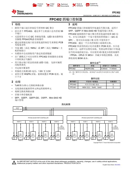
Copyright © 2017, Texas Instruments IncorporatedProduct Folder Order Now Technical Documents Tools &SoftwareSupport &CommunityFPC402ZHCSGY0A –JUNE 2017–REVISED OCTOBER 2017FPC402四端口控制器1特性•跨四个端口进行控制信号管理和I2C 聚合•结合多个FPC402,通过单个主机接口总共控制56个端口•无需使用分立式I2C 多路复用器、LED 驱动器和高引脚数FPGA/CPLD 控制器件•通过处理接近端口的全部低速控制信号来降低PCB 布线复杂性•可选I2C (高达1MHz )或SPI (高达10MHz )主机控制接口•从模块中自动预取用户指定的重要数据•在广播模式下可以对所有FPC402控制器的全部端口同时执行写操作•用于指示端口状态的高级LED 功能,包括可编程闪烁和调光•可定制中断事件•单独的主机侧I/O 电压:1.8V 至3.3V•采用小型WQFN 封装,能够放置在PCB 底部、端口下方2应用•ToR/聚合/核心交换机和路由器•无线基础设施基带单元和远程射频单元•视频交换机和路由器•存储卡和存储机架•SFP 、QSFP 、QSFP-DD 、OSFP 、Mini-SAS HD 端口管理3说明FPC402四端口控制器用作低速信号聚合器,适用于SFP 、QSFP 和Mini-SAS HD 等通用端口类型。
FPC402能够跨四个端口聚合所有低速控制和I2C 信号,并为主机提供一个易于使用的管理接口(I2C 或SPI )。
您可以在高端口数应用中使用多个FPC402,通过一个公共控制接口连接到主机。
FPC402所采用的设计允许放置在PCB 底部、压合连接器下方,这样可以简化布线。
凭借这种对端口中低速信号的本地控制方法,可以使用IO 数更少的控制器件(FPGA 、CPLD 和MCU )并减少布线层拥塞,从而降低系统BOM 成本。

DS-2DE4425IW-DE(T5)4 MP 25× Network IR Speed DomeHikvision DS-2DE4425IW-DE(T5) 4MP 25× Network IR Speed Dome adopts 1/2.8" progressive scan CMOS chip. With the 25× optical zoom lens, the camera offers more details over expansive areas.This series of cameras can be widely used for wide ranges of high-definition, such as the rivers, roads, railways, airports, squares, parks, scenic spots, and venues, etc. Empowered by deep learning algorithms, Hikvision AcuSense technology brings human and vehicle targets classification alarms to front- and back-end devices. The system focuses on human and vehicle targets, vastly improving alarm efficiency and effectiveness.⏹Focuses on human and vehicle targets classification based on deep learning⏹Support face capture. Up to 5 faces captured at the same time⏹1/2.8" progressive scan CMOS⏹High quality imaging with 4 MP resolution⏹Excellent low-light performance withpowered-by-DarkFighter technology⏹25× optical zoom and 16× digital zoom provide close up views over expansive areas⏹Expansive night view with up to 100 m IR distance⏹Support H.265+/H.265 video compression⏹DORIThe DORI (detect, observe, recognize, identify) distance gives the general idea of the camera ability to distinguish persons or objects within its field of view.It is calculated based on the camera sensor specification and the criteria given by EN 62676-4: 2015.DORI Detect Observe Recognize IdentifyDefinition25 px/m63 px/m125 px/m250 px/m Distance (Tele)2400.0 m (7874.0 ft)952.4 m (3124.7 ft)480.0 m (1574.8 ft)240.0 m (787.4 ft)⏹SpecificationCameraImage Sensor 1/2.8" progressive scan CMOSMax. Resolution 2560 × 1440Min. Illumination Color: 0.005 Lux @ (F1.6, AGC ON); B/W: 0.001 Lux @ (F1.6, AGC ON), 0 Lux with IR Shutter Speed 1 s to 1/30,000 sSlow Shutter YesDay & Night IR cut filterZoom 25x optical, 16x digitalLensFocus Auto, semi-auto, manualAperture Max. F1.6Zoom Speed Approx. 3.6 sFocal Length 4.8 mm to 120 mmFOV Horizontal field of view: 55° to 2.4° (wide-tele), Vertical field of view: 33° to 1.4° (wide-tele), Diagonal field of view: 61.5° to 2.8° (wide-tele)IlluminatorSupplement Light Type IRSupplement Light Range IR Distance: up to 100 m PTZProportional Pan YesPark Action Preset, pattern scan, patrol scan, auto scan, tilt scan, random scan, frame scan, panorama scanScheduled Task Preset, pattern scan, patrol scan, auto scan, tilt scan, random scan, frame scan, panorama scan, dome reboot, dome adjust, auxiliary outputMovement Range (Pan) 360°Movement Range (Tilt) -15° to 90° (auto flip)Pan Speed pan speed: configurable from 0.1° to 80°/s; preset speed: 80°/s Tilt Speed tilt speed: configurable from 0.1° to 80°/s, preset speed 80°/s Presets 300Patrol Scan 8 patrols, up to 32 presets for each patrolPattern Scan 4 pattern scansPower-off Memory Yes3D Positioning YesPTZ Status Display YesPreset Freezing Yes VideoVideo Compression Main stream: H.265+/H.265/H.264+/H.264 Sub-stream: H.265/H.264/MJPEGThird stream: H.265/H.264/MJPEGRegion of Interest (ROI) 8 fixed regions for each streamMain Stream 50 Hz: 25 fps (2560 × 1440, 1920 × 1080, 1280 × 960, 1280 × 720) 60 Hz: 30 fps (2560 × 1440, 1920 × 1080, 1280 × 960, 1280 × 720)Sub-Stream 50 Hz: 25 fps (704 × 576, 640 × 480, 352 × 288) 60 Hz: 30 fps (704 × 480, 640 × 480, 352 × 240)Third Stream 50 Hz: 25 fps (1920 × 1080, 1280 × 960, 1280 × 720, 704 × 576, 640 × 480, 352 × 288) 60 Hz: 30 fps (1920 × 1080, 1280 × 960, 1280 × 720, 704 × 480, 640 × 480, 352 × 240)Video Bit Rate 32 kbps to 16384 kbpsH.264 Type Baseline Profile/Main Profile/High ProfileH.265 Type Main profileScalable Video Coding (SVC) H.264 and H.265 encodingAudioAudio Compression G.711/G.722.1/G.726/MP2L2/PCMAudio Bit Rate 64 Kbps (G.711)/16 Kbps (G.722.1)/16 Kbps (G.726)/32-192 Kbps (MP2L2) Audio Sampling Rate 8 kHz/16 kHz/32 kHz/48 kHzEnvironment Noise Filtering YesNetworkNetwork Storage NAS (NFS, SMB/CIFS), auto network replenishment (ANR)Protocols IPv4/IPv6, HTTP, HTTPS, 802.1x, QoS, FTP, SMTP, UPnP, SNMP, DNS, DDNS, NTP, RTSP, RTCP, RTP, TCP/IP, UDP, IGMP, ICMP, DHCP, PPPoE, Bonjour, Websocket, WebsocketsAPI Open Network Video Interface (Version 19.12, Profile S, Profile G, Profile T), ISAPI, SDK, ISUPSimultaneous Live View Up to 20 channelsUser/Host Up to 32 users, 3 user levels: administrator, operator, and userSecurity Password protection, complicated password, HTTPS encryption, 802.1X authentication (EAP-TLS, EAP-LEAP, EAP-MD5), watermark, IP address filter, basic and digest authentication for HTTP/HTTPS, RTP/RTSP over HTTPS, control timeout settings, security audit log, TLS 1.2, TLS 1.3, host authentication (MAC address)Client iVMS-4200, HikCentral Pro, Hik-Connect Web Browser Chrome 57.0+, Firefox 52.0+, Safari 11+, IE11 ImageImage Parameters Switch YesImage Settings Saturation, brightness, contrast, sharpness, gain, and white balance adjustable by client software or web browserDay/Night Switch Day, Night, Auto, Schedule Wide Dynamic Range (WDR) 120 dBSNR > 52 dBDefog Digital defogImage Stabilization EISImage Enhancement BLC, HLC, 3D DNRPrivacy Mask 24 programmable polygon privacy masks, mask color or mosaic configurable Regional Focus YesRegional Exposure YesInterfaceEthernet Interface 1 RJ45 10M/100M self-adaptive Ethernet portOn-board Storage Built-in memory card slot, support microSD/SDHC/SDXC card, up to 256 GB Alarm 1 input, 1 outputAudio 1 input (line in), max. input amplitude: 2-2.4 vpp, input impedance: 1 kΩ ± 10%;1 output (line out), line level, output impedance: 600 ΩReset YesEventBasic Event Motion detection, video tampering alarm, exception, alarm input and outputSmart Event Line crossing detection, intrusion detection, region entrance detection, region exiting detection, unattended baggage detection, object removal detection, audio exception detectionAlarm Linkage Upload to FTP/NAS/memory card, notify surveillance center, send email, trigger alarm output, trigger recording, and PTZ actions (such as preset, patrol scan, pattern scan)Deep Learning FunctionFace Capture Detects up to 5 faces simultaneously.Supports detecting, capturing, grading, selecting of face in motion, and output the best face picture of the facePerimeter Protection Line crossing, intrusion, region entrance, region exitingSupport alarm triggering by specified target types (human and vehicle)GeneralPower 12 VDC, max. 18 W, including max. 1.6 W for heater and 9 W for IR; PoE (802.3at)Operating Condition -30 °C to 65 °C (-22 °F to 149 °F). Humidity 90% or less (non-condensing) Demist YesMaterial ADC12Dimensions Ø 164.5 mm × 290 mm (Ø 6.48" × 11.42")Weight Approx. 2 kg (4.41 lb.)ApprovalEMC FCC SDoC (47 CFR Part 15, Subpart B);CE-EMC (EN 55032: 2015, EN 61000-3-2: 2019, EN 61000-3-3: 2013, EN 50130-4: 2011 +A1: 2014);RCM (AS/NZS CISPR 32: 2015);IC VoC (ICES-003: Issue 6, 2019);KC (KN 32: 2015, KN 35: 2015)Safety UL (UL 62368-1);CB (IEC 60950-1:2005 + Am 1:2009 + Am 2:2013, IEC 62368-1:2014); CE-LVD (EN 62368-1:2014+A11:2017);BIS (IS 13252(Part 1):2010+A1:2013+A2:2015);LOA (SANS IEC60950-1)Environment CE-RoHS (2011/65/EU); WEEE (2012/19/EU); Reach (Regulation (EC) No 1907/2006)ProtectionIP66 (IEC 60529-2013), TVS 6000V lightning protection, surge protection and voltage transient protection⏹Typical ApplicationHikvision products are classified into three levels according to their anti-corrosion performance. Refer to the following description to choose for your using environment.This model has NO SPECIFIC PROTECTION.LevelDescriptionTop-level protectionHikvision products at this level are equipped for use in areas where professional anti-corrosion protection is a must. Typical application scenarios include coastlines, docks, chemical plants, and more.Moderate protectionHikvision products at this level are equipped for use in areas with moderate anti-corrosion demands. Typical application scenarios include coastal areas about 2 kilometers (1.24 miles) away from coastlines, as well as areas affected by acid rain.No specific protectionHikvision products at this level are equipped for use in areas where no specific anti-corrosion protection is needed.⏹Dimension⏹Available Model DS-2DE4425IW-DE(T5)⏹Accessory⏹IncludedDS-1618ZJ ⏹OptionalDS-1604ZJ DS-1604ZJ-BOX-CORNERDS-1604ZJ-pole DS-1661ZJ DS-1667ZJDS-1604ZJ-box DS-1619ZJ DS-1673ZJ DS-1604ZJ-BOX-POLEDS-1005KIDS-1604ZJ-corner DS-1662ZJ DS-1682ZJ DS-1663ZJ DS-1660ZJ DS-1681ZJ DS-1671ZJ-SDM9 DS-1100KI DS-1602ZJ。

ds402协议电流反馈DS402协议是一种用于电流反馈的通信协议,主要应用于工业自动化领域中的伺服驱动器和电机控制系统。
它通过数字信号传输电机的速度、位置和扭矩等参数,实现对电机运动的精确控制。
电流反馈是伺服驱动器中的一项重要功能,它能够实时监测电机的输出电流,并将监测到的电流信息反馈给控制系统。
通过对电流进行反馈控制,可以实现对电机的精确控制,提高系统的运动精度和响应速度。
DS402协议中定义了电流反馈的数据格式和通信规则,使得不同厂家生产的伺服驱动器和控制器能够实现互联互通。
协议中规定了电流反馈数据的采样率、精度和传输方式等参数,确保了数据的准确性和稳定性。
在DS402协议中,电流反馈数据以数字化的方式进行传输和处理。
伺服驱动器通过内置的A/D转换器将电流信号转换为数字信号,并将其发送给控制器。
控制器根据接收到的电流数据进行计算和控制,以达到预定的控制目标。
电流反馈在伺服控制系统中起着至关重要的作用。
它能够实时监测电机的负载情况,通过与预设值进行比较,及时调整控制参数,以实现电机的稳定运行。
电流反馈还可以用于检测电机的故障和异常情况,及时报警并采取相应的措施,保证系统的安全运行。
使用DS402协议进行电流反馈的伺服控制系统具有以下优点:1. 高精度:DS402协议规定了电流反馈数据的采样率和精度,能够实时准确地获取电机的电流信息,提高系统的控制精度和运动性能。
2. 高稳定性:DS402协议采用数字化的传输方式,能够有效抑制干扰信号和噪声,提高数据传输的稳定性和可靠性。
3. 高可扩展性:DS402协议是一种开放式的通信协议,能够与其他设备和系统进行互联互通,实现系统的可扩展性和灵活性。
4. 便于调试和维护:DS402协议提供了丰富的监测和诊断功能,能够实时监测电机的运行状态和性能参数,便于调试和维护工作。
DS402协议电流反馈是一种在工业自动化领域中广泛应用的控制技术。
它能够实时准确地获取电机的电流信息,实现精确控制和稳定运行。
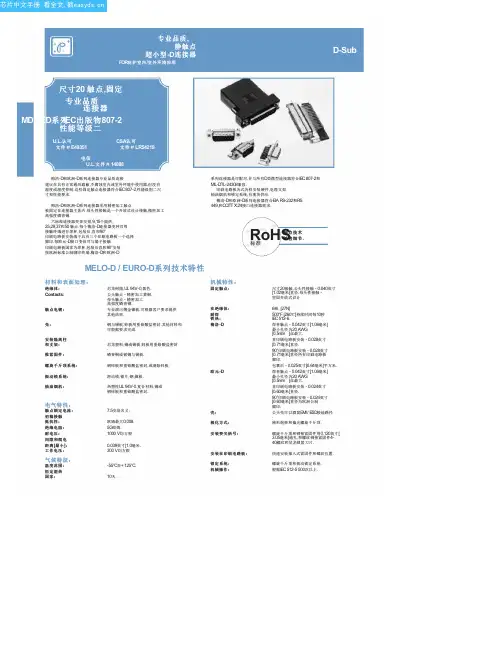
MELO-D / EURO-D 系列技术特性材料和表面处理:绝缘体:Contacts:触点电镀:壳:安装隔离柱和支架:推紧固件:螺旋千斤顶系统:振动锁系统:抽油烟机:尼龙树脂,U L 94V-0,黑色.公头触点 - 精密加工黄铜.母头触点 - 精密加工高强度磷青铜.专业演出薄金镍板.可根据客户要求提供其他结束.钢与锡板;锌板用重铬酸盐密封.其他材料和可根据要求完成.尼龙塑料,铜或锡板;锌板用重铬酸盐密封.磷青铜或铍铜与锡板.钢锌板和重铬酸盐密封,或清除锌板.滑动锁,锁片,钢,镍板.热塑性U L 94V-0.复合材料,铜或钢锌板和重铬酸盐密封.7.5安培名义.欧姆最大0.008.5G 欧姆.1000 V 均方根0.039英寸[1.0毫米.300 V 均方根-55°C 至+ 125°C .10天.机械特性:固定触点:在绝缘体:耐焊铁热:梅洛-D尺寸20接触,公头性接触 - 0.040英寸[1.02毫米]直径.母头性接触 -坚固开放式设计.电气特性:触点额定电流:初稿接触抵抗性:绝缘电阻:耐电压:间隙和爬电距离[最小]:工作电压:温度范围:恒定湿热国家:气候特征:6磅. [27N ]500°F [260℃]持续时间每10秒IE C 512-6.焊杯触点 - 0.042英寸[1.06毫米]最小孔径为20 AW G [0.5m m ]丝最大.直印刷电路板安装 - 0.028英寸[0.71毫米]直径.90°印刷电路板安装 - 0.028英寸[0.71毫米]直径所有印刷电路板脚印.包裹后 - 0.025英寸[0.64毫米]平方米.欧元-D焊杯触点 - 0.042英寸[1.06毫米]最小孔径为20 AW G [0.5m m ]丝最大.直印刷电路板安装 - 0.024英寸[0.60毫米]直径.90°印刷电路板安装 - 0.024英寸[0.60毫米]直径为欧洲公制脚印.壳:公头壳可以酒窝E M I / E SD 接地路径.极化方式:梯形炮弹和偏光螺旋千斤顶.安装要尖括号:螺旋千斤顶和铆接紧固件用0.120英寸[3.05毫米]通孔,和螺纹铆接紧固件4-40螺纹和尼龙锁紧刀片.安装在印刷电路板:快速安装推入式紧固件和螺纹位置.锁定系统:螺旋千斤顶和振动锁定系统.机械操作:根据IE C 512-5 500次以上.标准梅洛-D 和欧洲-D 系列连接器专业品质连接建议在具有正常通风遮蔽,不腐蚀室内或室外环境中使用器,但没有温度或湿度控制.这些固定触点连接器符合IE C 807-2,性能级别二尺寸和性能要求.梅洛-D 和欧洲-D 系列连接器采用精密加工触点被固定在连接器主体内.母头性接触是一个开放式设计接触,精密加工高强度磷青铜.六标准连接器变体安排,9,15个提供,25,29,37和50 触点.每个梅洛-D 连接器变种可用接触终端进行焊杯,包装后,直和90°印刷电路板安装端子具有三个印刷电路板一个选择脚印.每欧元-D 接口变体可与端子接触印刷电路板国家为焊杯,包装后直和90°安装按欧洲标准公制脚印终端.梅洛-D 和欧洲-D系列连接器是可配对,并与所有D 类微型连接器符合IE C 807-2和M IL-D TL-24308兼容.印刷电路板各式各样安装硬件,电缆支架抽油烟机和锁定系统,有现货供应.梅洛-D 和欧洲-D 系列连接器符合E IA R S-232和R S 449,和C C ITT X.24接口连接器需求.RoHS触点技术销售细节.公头性或母头性后视图正视图尺寸9尺寸15尺寸25尺寸29尺寸37尺寸50标准外壳组装B B1MK G10°典型.0.050±0.010[1.27±0.25]HE D1DC A 0.036±0.008[0.91±0.20]0.220 [5.59]M ax.Ø0.120±0.005 [Ø3.05±0.13]安装孔,两个地方可选壳组件[0,02]可选壳件与环球FLOAT支架[F]0.120±0.010 [3.05±0.25]Ø0.120±0.005 [Ø3.05±0.13]安装孔,两个地方不锈钢外壳(0选项)Ø0.154[3.91]安装孔,两地(02选项)1.213[30.81]1.213[30.81]1.541[39.14]1.541[39.14]2.088[53.04]2.088[53.04]1.770[44.96]1.770[44.96]2.729[69.32]2.729[69.32]2.635[66.93]2.635 [66.93]2.064[52.43]2.159[54.84]2.079[52.81]1.251[31.78]2.182[55.42]1.511[38.38]1.274[32.36]0.971[24.66]1.534[38.96]0.643[16.33]0.994[25.25]0.666[16.92]0.984[24.99]0.984[24.99]1.312[33.32]1.312[33.32]1.852[47.04]1.852[47.04]1.534[38.96]1.534[38.96]2.500[63.50]2.500[63.50]2.406[61.11]2.406[61.11]0.423[10.74]0.311[7.90]0.431[10.95]0.311[7.90]0.311[7.90]0.311[7.90]0.032 [0.81]总径向浮动量Ø0.086+0.005 Ø2.18+0.13-0.00-0.000安装孔,两个地方[]9M 9F 15 M 15 F 25 M 25 F 29 M 29 F 37 M 37 F 50 M 50 F 0.329[8.36]0.494[12.55]0.494[12.55]0.759[19.28]0.759[19.28]1.083[27.51]1.083[27.51]1.625[41.28]1.625[41.28]1.322[33.58]1.322[33.58]2.272[57.71]2.272[57.71]2.178[55.32]2.178[55.32]0.422[10.72]0.422[10.72]0.422[10.72]0.422[10.72]0.422[10.72]0.422[10.72]0.539[13.69]0.539[13.69]0.422[10.72]0.422[10.72]0.534[13.56]0.534[13.56]0.233[5.92]0.243[6.17]0.233[5.92]0.243[6.17]0.230[5.84]0.243[6.17]0.217[5.51]0.237[6.02]0.230[5.84]0.243[6.17]0.230[5.84]0.243[6.17]0.422[10.72]0.429[10.90]0.422[10.72]0.429[10.90]0.426[10.82]0.429[10.90]0.426[10.82]0.429[10.90]0.426[10.82]0.429[10.90]0.426[10.82]0.429[10.90]0.329[8.36]0.494[12.55]0.494[12.55]0.329[8.36]0.494[12.55]0.494[12.55]0.450[11.43]0.605[15.37]0.605[15.37]0.329[8.36]0.494[12.55]0.494[12.55]0.441[11.20]0.605[15.37]0.605[15.37]DIMENSIONS ARE IN INCHES [MILLIMET ERS].ALL DIMENSIONS ARE SUBJECT T O CHANGE.SOLDER CUP 连接器Fixed female jack s crews20 AW G max.[0.5 mm ]Fixed female jack s crewFixed male jack s crewIMPEDANCE [OHMS]AT T ENUAT ION [dB]0.135 [3.43]0.352 [8.94]对于焊杯触点,指定在步骤4代码2订购信息.修正公头性和母头性提供偏光螺旋千斤顶.指定订购信息步骤7码T6.典型型号:MD15M200T6Z典型型号:ED15M200T2Z直印刷电路板安装连接器332360.150[3.81]0.375[9.53]0.236[5.99]0.028[0.71]0.028[0.71]0.024[0.61]固定母头螺旋顶铆装隔板与推入式紧固件磷青铜0.225 [5.71]0.010 [0.25]M IN .对于直印刷电路板安装触点,在指定码数订购信息步骤4.LØD典型型号:MD25F3S60T0铁素体电感酒吧EMI / RFI 噪声抑制直印刷电路板安装连接器滤波特性铆装焊盘片与推进式紧固件磷青铜0.010 [0.25]最小MD MD MD MD ED ED DD ODD ODD HDC HDC HDC 32459636632325323660.375 [9.53]------------0.375 [9.53]0.375 [9.53]0.375 [9.53]0.515 [13.08]0.375 [9.53]------0.375 [9.53]0.375 [9.53]0.375 [9.53]0.240 [6.10]------------0.360 [9.14]0.101 [2.57]0.360 [9.14]0.165 [4.19]0.165 [4.19]------0.240 [6.10]0.101 [2.57]0.360 [9.14]固定母头螺旋顶IMPEDANCEALAT T ENUAT ION*90°印刷电路板安装连接器铁素体电感酒吧0.135±0.005[3.43±0.13]FREQUENCY *NO-LOAD CONDIT ION材料:镍锌陶瓷.指定订购信息步骤6代码F 或Q. F 代表铁素体电感和Q 为铁素体电感与推入式紧固件.Fixed female jack s crewsWRAP 柱连接器0.025 [0.64] Sq.0.495 [12.57]0.720 [18.29]对于包装后触点,请在订购信息步骤4码6.典型型号:MD15F600T20DIMENSIONS ARE IN INCHES [MILLIMET ERS].ALL DIMENSIONS ARE SUBJECT T O CHANGE.MD25M6S50T090°印刷电路板安装连接器代码5,0.283 [7.19]接触延伸CMD9*5R4*** MD15*5R4*** MD25*5R4***1.204[30.58]1.532[38.91]2.072[52.63]1.754[44.55]2.720[69.09]2.626[66.70]0.984[24.99]1.312[33.32]1.852[47.04]1.534[38.96]2.500[63.50]2.406[61.11]0.339[8.61]0.339[8.61]0.339[8.61]0.395[10.03]0.339[8.61]0.395[10.03]0.283[7.19]0.283[7.19]0.283[7.19]0.283[7.19]0.283[7.19]0.283[7.19]Fixed female jack s crewsB±0.008[0.20]AMD29*5R4***MD37*5R4***MD50*5R4***0.112 [2.84]典型.Specify code 5in s tep 4 of ordering informationNumbering s hown is rear viewof male and face view of female.0.112 [2.84]典型.DD0.112 [2.84]Typ.0.160 [4.06]标称典型型号:MD25M5R4NT2X0.125 [3.18]X 0.233 [5.92]Oval hole Typ.Pus h-on fas tenerberyllium copperØ0.028 [0.71]典型型号:MD50M5R4NT2X 90°印刷电路板安装连接器CODE 59,0.545 [13.84]接触延伸MD9*59B***1.204[30.58]1.532[38.91]2.072[52.63]1.754[44.55]2.720[69.09]2.626[66.70]0.984[24.99]1.312[33.32]1.852[47.04]1.534[38.96]2.500[63.50]2.406[61.11]0.275[6.99]0.275[6.99]0.275[6.99]0.275[6.99]0.275[6.99]0.275[6.99]0.545[13.84]0.545[13.84]0.545[13.84]0.545[13.84]0.545[13.84]0.545[13.84]0.601[15.27]0.601[15.27]0.601[15.27]0.657[16.69]0.601[15.27]0.657[16.69]Fixed f emale jackscrewsB±0.008[0.20]MD15*59B***AMD25*59B***MD29*59B***MD37*59B***MD50*59B*** CESpecif y code 59in step 4 of ordering inf ormation典型型号:MD29M59B0T2X0.112 [2.84]典型.0.112 [2.84]典型.DD0.112 [2.84]Typ.Numbering shown is rear viewof male and f ace view of f emale.0.125 [3.18]标称典型型号:MD25M59B0T2XØ0.028 [0.71]DIMENSIONS ARE IN INCHES [MILLIMET ERS].ALL DIMENSIONS ARE SUBJECT T O CHANGE.90°印刷电路板安装连接器CODE 4,0.450 [11.43]接触延伸Ø0.125[3.18]Typ.MD9*4B*** MD15*4B*** MD25*4B***1.204[30.58]1.532[38.91]2.072[52.63]1.754[44.55]2.720[69.09]2.626[66.70]0.984[24.99]1.312[33.32]1.852[47.04]1.534[38.96]2.500[63.50]2.406[61.11]0.506[12.85]0.506[12.85]0.506[12.85]0.562[14.27]0.506[12.85]0.562[14.27]0.450[11.43]0.450[11.43]0.450[11.43]0.450[11.43]0.450[11.43]0.450[11.43]CFixed f emale jackscrewsB±0.008[0.20]A MD29*4B***MD37*4B***MD50*4B***0.112 [2.84]典型.Specif y code 4in step 4 of ordering inf ormation D0.112 [2.84]Typ.Numbering shown is rear viewof male and f ace view of f emale.0.112 [2.84]典型.D0.160 [4.06]标称典型型号:MD25M4B0T20Ø0.028 [0.71]典型型号:MD50M4B0T2090°直印刷电路板接触孔图案与配合面安装连接器定位成遵循箭头方向.0.492 [12.50]Sym.0.216 [5.49]0.108 [2.74]Typ.0.656[16.66]Sym.0.378 [9.60]0.054 [1.37]Typ.Sym.0.926 [23.52]0.652 [16.56]0.109 [2.77]Typ.0.054 [1.37]Typ.0.112[2.84]0.162 [4.11]0.108 [2.74]Typ.0.112[2.84]0.324 [8.23]0.055 [1.40]Typ.0.598 [15.19]0.112[2.84] MD9Sym.MD15Sym.MD251.203[30.56]0.109[2.77]Typ.Sym.0.767[19.48] 0.224[5.69]0.432[10.97]0.108 [2.74]Typ.1.250 [31.75]0.978 [24.84]0.109[2.77]Typ.0.870[22.10]0.224[5.69]0.112 [2.84]0.054[1.37]Typ.0.486[12.34]0.055 [1.40]Typ.0.112[2.84]0.924 [23.47]0.055 [1.40]Typ.0.815 [20.70]0.112[2.84]MD29DIMENSIONS ARE IN INCHES [MILLIMET ERS]. ALL DIMENSIONS ARE SUBJECT T O CHANGE.MD37MD50建议0.045 [1.14]直径孔接触终止位置.建议0.123±0.003 [3.12±0.08]直径孔安装连接器推入式紧固件.。

512位读/写多用途非接触式识别装置译者:杭州电子科技大学杨四郎2013 /04 /07概述EM4205/4305是CMOS集成电路,主要用于电子射频读写应答器,它适用于低代价的动物标签应用的解决方案。
这款芯片的通信协议与EM4469/4569系列兼容。
EM4205与EM4305最主要的区别如下:◆EM4305为两个线圈输入增大了凸起的焊盘,EM4305的这个加大的凸起焊盘用于直接与天线相连,从而避免了需要使用一个模块。
◆EM4305提供了一个330p的谐振电容。
这款芯片通过外部线圈与内部集成电容一起组成的谐振电路,从连续的125kHz磁场中获取能量启动。
芯片从内部的EEPROM中读出数据,并通过与线圈并联的负载电阻的开断产生深幅调制,将数据发送出去。
通过对125kHz磁场的幅度调制,可以执行各种命令并更新EEPROM中的数据。
EM4205/4305支持双相编码和曼彻斯特编码。
EM4205/4305的运行模式储存在EEPROM的配置字中。
通过设置保护位,所有的EEPROM 字都可以被写保护。
这款芯片包含了工厂编程的32位唯一识别码(UID)。
特点◆16个32位的数据块组成512位EEPROM◆32位的唯一识别码(UID)◆32位的密码读写保护◆ISO11784/11785标准兼容◆可以将EEPROM锁定于只读状态◆两种数据编码方式:曼彻斯特和双相◆多种数据率:8,16,32,64个RF时钟◆读卡器(reader)先发话特点◆通信协议与EM4469/4569系列兼容◆100到150kHz的频率范围◆芯片自带整流器和限压器◆无需提供外部电容◆﹣40℃到+80℃的温度范围◆非常低的功耗◆增大的焊点(200μm×400μm)直接连接线圈(EM4305)◆EM4205:2个谐振电容210pF或250pF可掩膜选择,谐振电容可以做到工厂级,容忍3%的精度误差◆EM4305:3个谐振电容210pF、250pF或330pF可掩膜选择应用◆根据ISO FDX-B 用于动物识别◆鸽子的比赛标准◆废料管理标准◆门禁控制◆工业典型的运行配置图1绝对最大额定值Vss=0V表1超出上述所列的最大额定值将会导致器件永久性的损坏,超出特定的工作条件可能会影响器件的可靠性或导致故障。
Printed in U.S.A.TABLE OF CONTENTSPageSPECIFICATIONS . . . . . . . . . . . . . . . . . . . . . . . . . . . . . . . . . . . . . . . . . . . . . . 1INTRODUCTION . . . . . . . . . . . . . . . . . . . . . . . . . . . . . . . . . . . . . . . . . . . . . . . 1CONNECTOR CHART . . . . . . . . . . . . . . . . . . . . . . . . . . . . . . . . . . . . . . . . . . . . 1MEMORY MAP . . . . . . . . . . . . . . . . . . . . . . . . . . . . . . . . . . . . . . . . . . . . . . . . 1CIRCUIT ANALYSIS . . . . . . . . . . . . . . . . . . . . . . . . . . . . . . . . . . . . . . . . . . . . . 1BLOCK DIAGRAM . . . . . . . . . . . . . . . . . . . . . . . . . . . . . . . . . . . . . . . . . . . . 1DS2250 MICROPROCESSOR . . . . . . . . . . . . . . . . . . . . . . . . . . . . . . . . . . . . . . 1DUAL PORT RAM . . . . . . . . . . . . . . . . . . . . . . . . . . . . . . . . . . . . . . . . . . . . 1ON BOARD RAM U12 AND U13 . . . . . . . . . . . . . . . . . . . . . . . . . . . . . . . . . . . . 2OSCILLATOR . . . . . . . . . . . . . . . . . . . . . . . . . . . . . . . . . . . . . . . . . . . . . . . 2RESET . . . . . . . . . . . . . . . . . . . . . . . . . . . . . . . . . . . . . . . . . . . . . . . . . . . 2LOAD/RUN . . . . . . . . . . . . . . . . . . . . . . . . . . . . . . . . . . . . . . . . . . . . . . . . 2RS-232 INTERFACE . . . . . . . . . . . . . . . . . . . . . . . . . . . . . . . . . . . . . . . . . . . 2BIT I/O . . . . . . . . . . . . . . . . . . . . . . . . . . . . . . . . . . . . . . . . . . . . . . . . . . . 2LED INDICATORS . . . . . . . . . . . . . . . . . . . . . . . . . . . . . . . . . . . . . . . . . . . . 3TROUBLESHOOTING . . . . . . . . . . . . . . . . . . . . . . . . . . . . . . . . . . . . . . . . . . . . 3PROGRAMMING INSTRUCTIONSLOADING 344A4414G1 SOFTWARE INTO THE GETC 1e MODULE . . . . . . . . . . . . . . . . . 3REQUIRED ITEMS . . . . . . . . . . . . . . . . . . . . . . . . . . . . . . . . . . . . . . . . . . . . 3PREPARATION . . . . . . . . . . . . . . . . . . . . . . . . . . . . . . . . . . . . . . . . . . . . . . 3LOADING PROCEDURE . . . . . . . . . . . . . . . . . . . . . . . . . . . . . . . . . . . . . . . . 3ERRORS . . . . . . . . . . . . . . . . . . . . . . . . . . . . . . . . . . . . . . . . . . . . . . . . . . 3SERIAL NUMBERING . . . . . . . . . . . . . . . . . . . . . . . . . . . . . . . . . . . . . . . . . . 3PARTS LIST . . . . . . . . . . . . . . . . . . . . . . . . . . . . . . . . . . . . . . . . . . . . . . . . . . 4IC DATA . . . . . . . . . . . . . . . . . . . . . . . . . . . . . . . . . . . . . . . . . . . . . . . . . . . . 5HARNESS ASSEMBLY DIAGRAM . . . . . . . . . . . . . . . . . . . . . . . . . . . . . . . . . . . . . 7INSTALLATION INSTRUCTIONS . . . . . . . . . . . . . . . . . . . . . . . . . . . . . . . . . . . . . 7OUTLINE DIAGRAMS:HARNESS . . . . . . . . . . . . . . . . . . . . . . . . . . . . . . . . . . . . . . . . . . . . . . . . . 8GETC 1e . . . . . . . . . . . . . . . . . . . . . . . . . . . . . . . . . . . . . . . . . . . . . . . . . . 8SCHEMATIC DIAGRAM . . . . . . . . . . . . . . . . . . . . . . . . . . . . . . . . . . . . . . . . . .9MAINTENANCE MANUAL GE TRUNKING CARD 1e19D903536P1LBI-38822ACIRCUIT ANALYSISBLOCK DIAGRAMThe 1e module consists of two almost independent microprocessor (µP) sections (See Figure 2). The heart of each section is a DS2250 microprocessor, U1 or U2. In addition to its internal memory, each µP has a 32K byte external RAM, U12 or U13. Each section also contains a 4K byte dual port RAM (DPR), U3 or U4, which provides the interface to the GETC. A single oscillator, U14 provides clock for both processors. Each processor has a serial port which is converted to RS-232 by U8. Indicator LED’s D1 and D2 are activated by one-shots in U9 as long as they are triggered by the associated processor. A single input bit and a single output bit are available on each processor for I/O. The module has a single RESET button which resets both processors. LOAD/RUN circuits on each processor set op-erating mode. Port 1 and INT0 of both processors are tied together to provide a high speed parallel communication link between the two processors.DS2250 MICROPROCESSORThe microprocessor is a Dallas Semiconductor proprie-tary derivative of the Intel 8031. This special version proc-essor has internal circuitry for a bootstrap loader, terminal interface and internal control of 64K bytes of battery backed up RAM. The RAM can be partitioned into separate code and data spaces, with the code space write protected after code is loaded. An internal bit ECE2 under program control alters the memory map allowing access to all available memory.DUAL PORT RAMU3 and U4 provide the interface to the GETC 8032 processor. The GETC sees U3 and U4 as a single 8K byte memory block, addressed from 0 to 1FFFH. U1 sees U3 on its opposite port as a 4K byte RAM addressed from 0 to 0FFFH and likewise, U2 sees U4 as a 4K byte RAM ad-dressed from 0 to 0FFFH. Thus each 1e processor shares 4K bytes of memory space with the GETC processor, allowing efficient exchange of data. U11-D and U10-D drive the output enable (read) input from the GETC. U10-A, B, and C and U11-A and B drive DPR chip enables from the GETC.Copyright© January 1993, Ericsson GE Mobile Communications Inc.SPECIFICATIONSCurrent Drain80 to 120 ma.Supply Voltage 4.75VDC to 5.25VDCMemory Provided (bytes)64K on board, not backed up.128K in the DS2250’s, battery backed up.8K Dual PortRS-232 Serial Ports2I/O 2 bits input - Diode protected, weakly pulled upinverted before processor2 bits output - Transistor buffered, weakly pulled upopen collector.Oscillator frequency 1.0592 MHzIndicators One RED LED controlled by each DS2250 Dimensions 3.00in. x 7.75in. (board)INTRODUCTIONThe GETC 1e (expansion) module (19D903536P1) pro-vides additional processing power and memory for the G eneral E ectric T runking C ard (GETC) which will allow software growth, and expanded features for the E nhanced D igital A c-cess C ommunication S ystem (EDACS™). The 1e module is supplied standard with EDACS station GETC’s, Downlink GETC’s, CNI GETC’s, SCAT GETC’s, EDACS Site Control-ler GETC’s, Simulcast Control GETC’s, and EDACS Satellite Receiver GETC’s beginning in January 1993. The 1e module is not required, but is compatible with all previous hardware and software releases.The 1e module uses mostly surface mount components and mounts on spacers above the GETC. Electrical connections to the GETC are made by removing U3 from the GETC and plugging the 1e modules 28 pin ribbon cable and connector P1 into the GETC’s socket XU3. A small shield above the 1e module protects it from damage when sliding the GETC drawer in and out.CONNECTOR CHARTConnector DescriptionP11e module interface to the GETCaddress/data bus and powerJ1Allow serial interface to U2 at TTLlevelsJ2RS-232 serial interface to U1J3RS-232 serial interface to U2J4I/O on U1J5I/O on U2Figure 1 - Memory Map For Each DS2250MEMORY MAPLBI-38822LBI-388221ON BOARD RAM U12 AND U13When ECE2 is 0, each processor accesses a 32K RAM at address 8000H to 0FFFFH. These RAM’s are on the 1e module board, not on the DS2250, thus they are not backed up by the DS2250 battery. This memory space is used as temporary scratch pad by the processors. U10-E and U10-F drive the RAM CE (chip enable) pin from bit 15 of the address bus. A low enables the RAM.OSCILLATORU14 is an unbuffered CMOS inverter (HCU04). Here, U14-A functions as a linear gain stage with crystal Y1 in its feedback, forming an oscillator at 11.0592 MHz. U14-B buff-ers the clock and drives both processors.RESETSwitch S1 resets the 1e module and S4 on the GETC resets the GETC. Software will usually start properly with only a GETC reset, however resetting both will work.Depressing switch S1 grounds R21 and R22 and the posi-tive side of C21. This turns on PNP transistors Q4 and Q7 which pulls the RESET input of each processor high, holding them in the RESET condition. When S1 is released, the voltage at C21+ (and Q4 and Q7 bases) slowly rises as C21 charges through R8 and R15. Eventually this voltage rises high enough so Q4 and Q7 turn off and the processor RESET inputs fall low and are held low by R7 and R14. R8 and R15 hold Q4 and Q7 off.LOAD/RUN CIRCUITIn normal RUN mode, the processors RESET input is held low and PSEN is an output which controls external memory. The DS2250 is put into LOAD mode by holding the RESET pin high and the PSEN pin low.Switch S2 controls RUN/LOAD for processor U1. When S2 is down (toward S1) (shorting pins 2 and 3) U1 is in LOAD mode. VCC (5V) is applied to R10 and R12. This turns on Q8 which turns on Q7 through R9 thus pulling U1’s RESET high. VCC on R12 turns on Q6 which holds PSEN low. When S2 is up (shorting pins 1 and 2) the processor is in RUN mode. VCC is not applied to R10 and R12. Q8 is held off by R11 and Q7is held off by R8 so RESET is pulled low by R7. Q6 is held off by R13 so PSEN is not held low and may become an output of U1.Switch S3 controls RUN/LOAD for processor U2. When S3 is down (shorting pins 2 and 3) U2 is in LOAD mode. VCC (5V) is applied to R17 and R19. This turns on Q5 which turns on Q4 through R16 thus pulling U2’s RESET high. VCC on R19 turns on Q3 which holds PSEN low. When S3 is up (shorting pins 1 and 2) the processor is in RUN mode. VCC is not applied to R17 and R19. Q5 is held off by R18 and Q4 is held off by R15 so RESET is pulled low by R14. Q3 is held off by R20 so PSEN is not held low and may become an output of U2.RS-232 INTERFACEThe RS-232 interfaces are used to program the DS2250 modules and to interface to other serial devices (future appli-cations). An Intel Hex format file from a PC can be loaded into memory via the serial ports. Complete instructions will accom-pany software loaded in the field.U8 is a dual TTL to RS-232 duplex serial interface. Ca-pacitors C1, C2, C3, and C4 are used by U8 to convert 5V to RS-232 levels. Section 1 converts U1’s serial port to RS-232 and section 2 converts U2’s serial port to RS-232. Serial output for U1 is J2-1 and input is J2-2. Serial output for U2 is J3-1 and input is J3-2. J1 is inserted in the RXD line of U2 to allow interfacing to U2’s serial port at TTL levels.BIT I/OOne output bit from U1 is available. It is buffered by Q9 and drives out on J4-2. Weak pullup R30 holds J4-2 high when Q9 is turned off by U1. One input bit to U1 is available. It is buffered by U15-A and protected from static and overdrive by D3 and R27. Weak pullup R35 holds the input high when not in use.One output bit from U2 is available. It is buffered by Q10 and drives out on J5-2. Weak pullup R32 holds J5-2 high when Q9 is turned off by U1. One input bit to U2 is available. It is buffered by U15-B and protected from static and overdrive by D4 and R31. Weak pullup R36 holds the input high when notin use.Figure 2 - GETC 1e Block DiagramLBI-38822LBI-38822 2LED INDICATORSLED D1 is controlled by processor U1. The processor must apply pulses to retriggerable one-shot U9-A, pin 4, about every half second or faster to keep the light on. It is used as a visual indication that the software is running. The pulse on U9-4 retriggers the output on U9-6 keeping Q1 on and LED D1 on. If the pulses don’t appear in time, the one-shot times out and U9-6 falls low turning off Q1 and D1. R1 and C17 determine the drop out time.LED D2 is controlled by processor U2. The processor must apply pulses to retriggerable one-shot U9-B, pin 12, about every half second or faster to keep the light on. It is used as a visual indication that the software is running. The pulse on U9-12 retriggers the output on U9-10 keeping Q2 on and LED D2 on. If the pulses don’t appear in time, the one-shot times out and U9-10 falls low turning off Q2 and D2. R4 and C18 determine the drop out time.TROUBLESHOOTINGVery little troubleshooting is possible in the field. Prob-lems may be traced to the 1e module by substituting another 1e module. If it is not known that the substitute module has correct software, either load correct software into it or take the DS2250 modules out of the suspect 1e and put them into the new 1e. If DS2250 modules are substituted, be sure to put U1 from the old 1e into XU1 of the new 1e and likewise for U2. The two processors will generally contain different software.If problems can be traced to the 1e module, here are some things to look for. Visually check for damaged parts, un-soldered pins or parts, broken cable or pins (P1), or unseated DS2250 modules. Look for trash in the SIMM sockets. A magnifying glass or low power microscope is helpful. Make sure S2 and S3 are positioned toward the rear of the GETC in the RUN condition. Make sure the jumper is on J1-1 to 2. Check for 5V 0.25V at C5+. With a high speed, high impedance scope, check for oscillations at U14-4. A somewhat flattened sine wave of about 4V amplitude at 11.0592 Mhz will be seen.PROGRAMMING INSTRUCTIONSLOADING 344A4414G1 SOFTWARE INTOTHE GETC 1e MODULEREQUIRED ITEMS•IBM compatible PC, monitor and keyboard with atleast 640K memory,•Hard disk (recommended but not required) and serialport (COM1)•TQ-3360 programming cable•DB-25 male to DB-9 female adapter or cable (neededif PC COM1 connector is DB-9 male instead of DB-25 male)•Software Distribution diskette 344A4414G1PREPARATIONBefore loading can begin, the files listed below must existon the PC used as the loader. Create a new directory, forinstance, "LOAD1e" with the command "MKDIRLOAD1E". Then change into that directory and copy thefollowing files from the distribution diskette.load1e.exe1etop.hex1ebot.hex1ecrc.hexAlways change to this directory before loading softwareto 1e modules.The executable file "load1e.exe" loads the file"1etop.hex" into the top processor on the 1e module. Thisprocessor is physically in the rear as viewed from the front ofthe GETC and it accesses the top half of GETC RAM memoryspace (1000-1FFF). It is loaded through J2 and J104. Then"load1e.exe" loads file "1ebot.hex" into the bottom proces-sor on the 1e module. This processor is physically in the front,accesses the bottom half of GETC memory (0-FFF) and isserially loaded through J3 and J103. The loader uses file"1ecrc.hex" to check that the file was loaded correctly.This procedure assumes loading will occur after the iemodule is mounted in a GETC and installed in an EDACSstation.LOADING PROCEDURE1.Connect loader cable TQ-3360 from COM1 on thePC to J104 at rear of GETC. A DB-25 male to DB-9female adapter or cable may be required.2.Move S2 and S3 on the 1e module toward the front.If either switch is already positioned to the front,move it to the rear and then back to the front.3.Execute program LOAD1E and follow its instruc-tions. You will be kept informed of execution steps.After the top processor is loaded, move the program-ming cable to J103, then hit a key to load the bottomprocessor.4.When both processors are loaded correctly, thescreen will say "FINISHED - SWITCH S2 AND S3TO THE REAR". Do so and D1 and D2 shouldcome on to indicate code is executing. Unplug theprogramming cable.ERRORSErrors usually mean communications have been lostbetween the PC and the 1e module. If errors occur, checkcables, plugs, and move S2 and S3 to the rear then backtoward the front.Error 1 Did not receive signon banner from DS-2250.Error 2 Did not receive CR-LF from DS-2250.Error 3 Did not receive prompt from DS-2250.Error 4 Did not receive CRC value from DS-2250.Error 5 Did not receive serial number from DS-2250."Cannot open COM1" - COM1 on the PC is non-existentor in use by other software or hardware. A PC re-configu-ration is required."Cannot open ’filename’" - Be sure file exists in theappropriate directory."BAD CRC" - A CRC error means that after loading,memory contents are incorrect or the wrong 1ecrc.hex filewas used. If 1ecrc.hex is the same version shipped withthe software, a 1e module hardware problem is indicated."Wrong serial number-check cables" - If cabling iscorrect, DS-2250 stiks may have been swapped. The fourbyte serial number is printed to the screen to help inrestoring DS-2250’s to their proper locations. The fourbyte serial numbers must be the same for both DS-2250’sexcept that the least significant byte must be an oddnumber for the top DS-2250 and exactly one less for thebottom DS-2250."Illegal serial number" - Serial number is either invalid,was never programmed, or has been erased.*******END OF PROGRAMMING SPEC*******SERIAL NUMBERINGEach DS-2250 contains a unique serial number. Toavoid loading software to the wrong DS-2250, the loaderprogram, 1eload.exe, uses these serial numbers to checkcabling during programming. GETC code will check DS-2250 serial numbers and will not operate if serial numbersare in the wrong location or if the two serial numbers do notcompare correctly.Do not swap DS-2250 stiks in a 1e module or take oneDS-2250 from a 1e and put it in another 1e. It is permissibleto swap DS-2250’s as pairs if the top and bottom positionsare maintained.LBI-38822LBI-388223PARTS LISTSYMBOL PART NUMBER DESCRIPTION— — — CAPACITORS— — — C119A705205P21Tantalum: 22 µf ±20%, 20 VDCW.thruC5C619A702052P14Ceramic: .01 µf ±10%, 50 VDCW.thruC24C1719A705205P19Tantalum: 2.2 µf ±20%, 10 VDCW.andC18C1919A702061P35Ceramic: 30 pf ±5%, 50VDCW.andC20C2119A705205P2Tantalum: 1 µf ±20%, 16 VDCW.— — — — DIODES— — — — D1HP HSMS-T400LEDandD2D319A700053P2Silicon: 2Diode, Fast Recovery, 250 and mA, 70 PIV.D4— — — — JACKS— — — — J122-12-20343Pin; MolexthruJ5J822-10-20919Pin; MolexandJ9— — — — PLUGS— — — — P119B802001P1Header, 14X2; Samtec SpecialSEP-50546-1.7/01— — — TRANSISTORS— — — Q119A700076P2Transistor; NPN, 3904thruQ3,Q5andQ6,Q8thruQ10Q419A700059P2Transistor; PNP, 3906andQ7SYMBOL PART NUMBER DESCRIPTION— — — — RESISTORS— — — — R119B800607P473Metal Film: 47k ohms ±5%, 1/8 w.R219B800607P103Metal Film: 10k ohms ±5, 1/8 w.R319B800607P102Metal Film: 270 ohms ±5%, 1/8 w.R419B800607P473Metal Film: 47k ohms ±5%, 1/8 w.R519B800607P103Metal Film: 10k ohms ±5%, 1/8 w.R619B800607P271Metal Film: 270 ohms ±5%, 1/8 w.R719B800607P102Metal Film: 1k ohms ±5%, 1/8 w.R819B800607P103Metal Film: 10k ohms ±5%, 1/8 w.thruR13R1419B800607P102Metal Film: 1k ohms ±5%, 1/8 w.R1519B800607P103Metal Film: 10k ohms ±5%, 1/8 w.thruR22R2319B800607P105Metal Film: 1M ohm ±5%, 1/8 w.R2419B800607P102Metal Film: 1k ohms ±5%, 1/8 w.R2519B800607P104Metal Film: 100k ohms ±5%, 1/8 w.andR26R2719B800607P101Metal Film: 100 ohms ±5%, 1/8 w.R2819B800607P103Metal Film: 10k ohms ±5%, 1/8 w.andR29R3019B800607P104Metal Film: 100k ohms ±5%, 1/8 w.R3119B800607P101Metal Film: 100 ohms ±5%, 1/8 w.R3219B800607P104Metal Film: 100k ohms ±5%, 1/8 w.R3319B800607P103Metal Film: 10k ohms ±5%, 1/8 w.andR34R3519B800607P104Metal Film: 100k ohms 5%, 1/8 w.andR36— — — — SWITCHES— — — — S119A701324P1SW, PUSHBUTTON.S2ALCO SE1DGPC SW, 2 Position Slide.andS3— —INTEGRATED CIRCUITS— — U1DS2250-64-12Microcontroller SipStik.andU2U3IDT 7134S70J CMOS Dual-Port RAM, 32k (4kX8-Bit).andU4U519A703471P318Octal 3-State Noninverting Transparent and Latch, 74HC573.U6U819A149446P2RS-232 Drivers/Receivers, MAX232A.U9MC514538BDW Multivibrator (Retriggerable,Resettable).U1019A703483P304Hex Inverter, 74HC04AU1119A703483P302Quad 2-Input NAND Gate, 74HC00.GETC 1e MODULE19D903536P1 (344A3912G1, Rev. 0)Issue 1SYMBOL PART NUMBER DESCRIPTION U1219A705981P101Static RAM (SRAM), HM62256A.andU13U1419A703995P2Hex Unbuffered Inverter, 74HCU04.U1519A703483P321Hex Schmitt-Trigger Inverter, 74HC14.— — — — CRYSTALS— — — — Y119A702511G2611.059 MHz.— — — — SOCKETS— — — — XU1AMP 4-382486-0SIMM Socket.andXU2— — — — JUMPERS— — — — P219A702104P1Jumper.BIVAR CI-192-028Insulator (Under Y1).XETEL 42-000967Printed Wire Board.— — — MISCELLANEOUS— — —HARDWARE KIT344A4019G1(1e Installation) 119B802166P1Guard319B201955P9SPC, Thread4N84P13004B6Screw, Machine519A701365P8Washer6N80P13004B6Screw, machine: Pan head;No. 6-32 x 1/4".7N404P13B6Lockwasher, internal tooth: No. 6.84035306P25Washer, Fiber.919J706152P5Strap, Retaining.HARNESS INSTALLATIONHARDWARE KIT19C337712G17160861P33Clip.19A134011P1Screw (wire tie).LBI-38822LBI-38822 4IC DATA MICROCONTROLLER U1/U2DS2250DUAL PORT SRAM U3/U4IDT7134S70J (344A3040P201)OCTAL 3-STATE NONINVERTING TRANSPARENT LATCH U5, U619A703471P318 (74HC573)RS-232 DRIVERS/RECEIVERS U819A149446P2 (MAX232A)MULTIVIBRATOR (Retriggerable, Resettable) U9MC14538BDWHEX INVERTER U1019A703483P304LBI-38822LBI-388225IC DATAQUAD 2-INPUT NAND GATE U11 19A703483P302 (74HC00) STATIC RAM U12, U1319A705981P101 (62256)HEX UNBUFFERED INVERTER U1419A703995P2 (74HCU04)HEX SCHMITT-TRIGGER INVERTER U15 19A703483P321 H(74HC14)LBI-38822LBI-38822 6INSTALLATION INSTRUCTIONSHARNESS ASSEMBLY(19C337712, Sh. 1, Rev. 0)(19D438125, Sh. 3, Rev. 6) LBI-38822LBI-388227OUTLINE DIAGRAM GETC 1e Module(19D903536, Rev. 1)HARNESS(19D904442, Sh. 1, Rev. 0)LBI-38822LBI-388228SCHEMATIC DIAGRAMLBI-38822LBI-38822GETC 1e Module(19D903613, Sh. 1, Rev. 0)9SCHEMATIC DIAGRAMGETC 1e Module(19D903613, Sh. 2, Rev. 0)LBI-38822LBI-38822 10LBI-38822LBI-38822This page intentionally left blank11。
DS402ST中⽂资料APPLICATIONSs Rectification s Freewheel Diode s DC Motor Control s Power Supplies s Welding s Battery Chargers FEATURESs Double Side Cooling s High Surge CapabilityVOLTAGE RATINGSKEY PARAMETERSV RRM 1400V I F(AV)505A I FSM 5600A14001300120011001000900DS402ST14DS402ST13DS402ST12DS402ST11DS402ST10DS402ST09Conditions V RSM = V RRM + 100VLower voltage grades available.Type NumberRepetitive PeakReverse VoltageV RRM VOutline type code: T.See Package Details for further information.CURRENT RATINGSSymbolParameterConditionsDouble Side Cooled I F(AV)Mean forward current I F(RMS)RMS valueI FContinuous (direct) forward currentSingle Side Cooled (Anode side)I F(AV)Mean forward current I F(RMS)RMS valueI FContinuous (direct) forward currentUnitsMax.Half wave resistive load, T case = 100o C 505A T case = 100o C 793A T case = 100o C640AHalf wave resistive load, T case = 100o C 365A T case = 100o C573A T case = 100o CA DS402STRectifier DiodeReplaces March 1998 version, DS4183-2.3DS4183-3.0 January 2000SURGE RATINGSConditions10ms half sine; T case = 175o C V R = 50% V RRM - 1/4 sine 10ms half sine; T case = 175o C V R = 0Max.Units Symbol ParameterI FSM Surge (non-repetitive) forward current I 2t I 2t for fusingI FSM Surge (non-repetitive) forward current I 2tI 2t for fusingA 2s5.6kA 101 x 103A 2s 4.5kA THERMAL AND MECHANICAL DATAdc ConditionsMin.Max.UnitsoC/W -0.16Anode dcClamping force 4.5kN with mounting compound Thermal resistance - case to heatsinkR th(c-h)0.02Double side -175oC T vj Virtual junction temperatureT stg Storage temperature range Reverse (blocking)Single side-Thermal resistance - junction to caseR th(j-c)Single side cooledSymbolParameterClamping force3.55.0-55200oC-On-state (conducting)-185oC-0.04oC/WoC/W Cathode dc-0.16oC/W Double side cooled-0.08oC/WCHARACTERISTICSForward voltage Peak reverse current ParameterSymbol V FM I RRM At V RRM , T case = 175o C -15mA - 1.25V At 450A peak, T case = 25o C ConditionsMin.Max.Units 155 x 103At T vj = 175?C-V TO Threshold voltage r TSlope resistance0.84m ?At T vj = 175?C -0.81VCURVESFig. 2 Dissipation curvesFig. 3 Surge (non-repetitive) forward current vs time (with 50% V RRM , T case = 175?C)PACKAGE DETAILSFor further package information, please contact your local Customer Service Centre. All dimensions in mm, unless stated otherwise.DO NOT SCALE.ASSOCIATED PUBLICATIONSTitleApplication NoteNumber Calculating the junction temperature or power semiconductors AN4506Recommendations for clamping power semiconductors AN4839Thyristor and diode measurement with a multi-meter AN4853Use of V TO, r Ton-state characteristicAN5001POWER ASSEMBLY CAPABILITYThe Power Assembly group was set up to provide a support service for those customers requiring more than the basic semiconduc-tor, and has developed a flexible range of heatsink / clamping systems in line with advances in device types and the voltage and current capability of our semiconductors.We offer an extensive range of air and liquid cooled assemblies covering the full range of circuit designs in general use today. The Assembly group continues to offer high quality engineering support dedicated to designing new units to satisfy the growing needs of our customers.Using the up to date CAD methods our team of design and applications engineers aim to provide the Power Assembly Complete solution (PACs).DEVICE CLAMPSDisc devices require the correct clamping force to ensure their safe operation. The PACs range offers a varied selection of pre-loaded clamps to suit all of our manufactured devices. This include cube clamps for single side cooling of ‘T’ 22mm Clamps are available for single or double side cooling, with high insulation versions for high voltage assemblies.Please refer to our application note on device clamping, AN4839HEATSINKSPower Assembly has it’s own proprietary range of extruded aluminium heatsinks. They have been designed to optimise the performance or our semiconductors. Data with respect to air natural, forced air and liquid cooling (with flow rates) is available on request.For further information on device clamps, heatsinks and assemblies, please contact your nearest Sales Representative or the factory.CUSTOMER SERVICE CENTRESFrance, Benelux, Italy and Spain T el: +33 (0)1 69 18 90 00. Fax: +33 (0)1 64 46 54 50North America T el: 011-800-5554-5554. Fax: 011-800-5444-5444UK, Germany, Scandinavia & Rest Of World T el: +44 (0)1522 500500. Fax: +44 (0)1522 500020SALES OFFICES France,Benelux,ItalyandSpainTel:+33(0)169189000.Fax:+33(0)164465450GermanyTel************North America T el: (613) 723-7035. Fax: (613) 723-1518. T oll Free: 1.888.33.DYNEX (39639) /T el: (831) 440-1988. Fax: (831) 440-1989 / Tel: (949) 733-3005. Fax: (949) 733-2986.UK, Germany, Scandinavia & Rest Of World Tel: +44 (0)1522 500500. Fax: +44 (0)1522 500020These offices are supported by Representatives and Distributors in many countries world-wide.? Dynex Semiconductor 2000 Publication No. DS4183-3 Issue No. 3.0 January 2000TECHNICAL DOCUMENTATION – NOT FOR RESALE. PRINTED IN UNITED KINGDOMHEADQUARTERS OPERATIONS DYNEX SEMICONDUCTOR LTD Doddington Road, Lincoln.Lincolnshire. LN6 3LF. United Kingdom.Tel: 00-44-(0)1522-500500Fax: 00-44-(0)1522-500550DYNEX POWER INC.Unit 7 -58 Antares Drive,Nepean, Ontario, Canada K2E 7W6.T el: 613.723.7035Fax: 613.723.1518T oll Free: 1.888.33.DYNEX (39639)This publication is issued to provide information only which (unless agreed by the Company in writing) may not be used, applied or reproduced for any purpose nor form part of any order or contract nor to be regarded as a representation relating to the products or services concerned. No warranty or guarantee express or implied is made regarding the capability, performance or suitability of any product or service. The Company reserves the right to alter without prior notice the specification, design or price of any product or service. Information concerning possible methods of use is provided as a guide only and does not constitute any guarantee that such methods of use will be satisfactory in a specific piece of equipment. It is the user's responsibility to fully determine the performance and suitability of any equipment using such information and to ensure that any publication or data used is up to date and has not been superseded. These products are not suitable for use in any medical products whose failure to perform may result in significant injuryor death to the user. All products and materials are sold and services provided subject to the Company's conditions of sale, which are available on request.All brand names and product names used in this publication are trademarks, registered trademarks or trade names of their respective owners./doc/9a32027f8e9951e79b89274f.htmle-mail: power_solutions@/doc/9a32027f8e9951e79b89274f.htmlDatasheet Annotations:Dynex Semiconductor annotate datasheets in the top right hard corner of the front page, to indicate product status. The annotations are as follows:-Target Information: This is the most tentative form of information and represents a very preliminary specification. No actual design work on the product has been started.Preliminary Information: The product is in design and development. The datasheet represents the product as it is understood but details may change.Advance Information: The product design is complete and final characterisation for volume production is well in hand.No Annotation: The product parameters are fixed and the product is available to datasheet specification.。
It’s easy to create a CANopen compliant DSP-402 drive,isn’t it?Torsten Gedenkport GmbH, Germany1. IntroductionModern drives systems can be adapted to the most different custom-designed require-ments and integrated into all sorts of communication networks. As a robust field bus sys-tem CANopen finds increasingly use in drive applications. Therefore many users are fac-ing the necessity to integrate the CANopen communication profile into their drives.Figure 1 - Structure of a CANopen deviceThe CANopen software must provide all components necessary for a CANopen drive as represented in the figure 1.To achieve this, the following considerations play a decisive role:1. How to achieve the fastest and most cost effective implementation in conformitywith the CANopen standard?2. How is the implementation carried out?3. Which software tools are available?4. Which of these are, in addition, useful?This article describes how a CANopen drive can be developed successfully in shortest time with the aid of software tools.2. Components of a CANopen driveThe CiA has published different standards for the communication in a CANopen net-work. The available CANopen services are defined in the communication profile DS-301. Special drive functions with their parameters are defined in the "Device profiles Drives and Motion Control" DSP-402.The DSP-402 defines the behavior of a drive at the start, the configuration and the execution of motion sequences by a state machine.A CANopen drive can be divided into following parts:•drive application•communication stack and special drive profile in conformity with the standards DS-301 and DSP-402.•object dictionary•CAN driver interfaceThe drive application is not CANopen specific and therefore shall not be examined in detail. The communication interface and protocol software provide services to transmit and to receive communication objects over the bus. The object dictionary describes these data types, communication objects and application objects used in this drive.Conse-quently the most important part of a CANopen drive is the object dictionary.All data and parameter of a drive,which should be visible from CAN, are stored in the object dictio-nary and can be reached via the object dictionary.It is the interface to the application software. The application program provides the internal control functionality as well as the interface to the process hardware interfaces. The CAN driver is the interface to send and receive CAN messages.Possible realization variants are:•drive application and CANopen communication on one micro controller or•further use of the available drive controller and CANopen communication on a separate communication processor with a RS485 connection, a dual port RAM or another solu-tion for data interchange.The advantage of the first variant are the lower manufacturing costs.In contrast to that the second variant ensures that the full power of the micro controller is available for the drive control. Additionally,the reuse of existings drive components may save dev e lop-ment time.3. Software requirementsIn order to implement the CANopen functionality an individualized CANopen stack could be developed or alternatively,an already available CANopen stack could be uti-lized.The efforts for the development of an individually designed CANopen stack appears to be substantial when the necessary standards and possible requirements of implementing the CANopen conformance tests, together with the CANopen drive,are taken into considera-tion. This means that it would be preferable to invest in an available stack.Further arguments against developing an individualized CANopen stack are the benefits available to the user of a ready-made stack.These include, for example, the guaranteed updating service or the special support for implementation offered by the provider of the CANopen stack.All relevant protocol stacks on the market are written in ANSI-C and therefore cover the main use case since more than 90% of the drive software is implemented in this program-ming language.This does not rule out that special parts of the drive control are written in assembler.Depending on the drive application to be realized the operation modes have to be imple-mented and their extent have to be defined. DSP-402defines operating modes with mandatory objects for each mode.Additional functionality can be implemented by optional objects and even manufacturer specific objects.The design of the CANopen interface to an existing drive application depends a lot on the requirements and on the structure of the application.The interface can contain:•the state machines defined in DS-301 and DSP-402,•the object dictionary and•a signalisation of all CANopen events.The simplest way of linking is the use of the application variables in the object dictionary. While the drive application is using the variable like before, it can be accessed via CANopen using SDOs.For further services (e.g. transmission of a PDO) the CANopen stack provides functions.pdoNr = 1;writePdoReq( pdoNr );Listing 1 - Transmission of a PDOThese functions encapsulate all related actions, like the following for the example above (listing 1):•Check of the NMT state•Check of the inhibit time, if necessary•Preparation of the PDO data by reading the corresponding values from the object dic-tionary (e.g. status word and actual position)•Transmission of the PDO, if it is asynchronous•or storage of the PDO in the SYNC buffer,if it is a synchronous PDOTo inform the application about CANopen requests, CallBack functions are used.On occurence of a CANopen event (Indication) the corresponding CallBack function is called. In this function the application can react to the event, if necessary.4. Design of the Object DictionaryThe most important part of the development of a CANopen drive is the design of the object dictionary.An object dictionary is difficult to create.In addition to the process data it contains value ranges, initialization values, access attributes and including the manufacturer’s parame-ters, which have to be set up in conformity with the standards and the application.Appli-cation data can be C variables that have to be assigned to the objects.It is sensible to maintain these data in a general data base and to use a software tool to generate the object dictionary in implementation code (mostly in C).The used database can also be used for the creation of Electronic Data Sheets (EDS).This automatically produces the advantage of an exact conformity with the implementation of the device and the EDS.If the input of the device specific interpretation of the parameters can be organized through a yet more detailed description, the developer can get a documentation of the device at the same time with little additional effort. This documentation serves not only as the basis of the user documentation, but is also helpful to maintenance and test tasks.Figure 2 - CANopen Design ToolThere are the the following advantages:•Such tools provide drive data bases, from which an object dictionary in C-code, an Electronic Data Sheet and a documentation are produced automatically.•The generated C-source code of the object dictionary is included by the application modules. This ensures the direct access to the variables (via variable names) and the access via index and sub-index.•These tools take over error-prone tasks and repetitious jobs and supports the implemen-tation part.5. Test of the CANopen driveThe next step is the integration of the drive into a network respectively the test of the drive.A CAN-analyser is indispensable for the implementation of CANopen networks and the integration of CANopen equipment.A CAN-analyser provides the online obser-vation of the bus traffic, sending unique or cyclic messages and whole message sequences as well as recording of the CAN messages and storing into logging files.It is advisable if supplementary software modules provide extended functions like a CANopen specific representation of the messages.Besides a CAN-Analyzer it is helpful to use a tool that allows the configuration of the CANopen drives in a CANopen network. Furthermore the access to the implemented CANopen services should be possible and it should be supported to write test or control applications. The test software must be able to import the EDS file or the device descrip-tion file (ISO-15745-compliant) of the device to get information about the representation of the object dictionary.For such an integration and test of CANopen devices resp. networks the CANopen Device Monitor (CDM, figure 3) can be used.Its scripting capability facilitates tests and can be used for network control.The following listing (listing 2) shows an example script for drives in the profile position mode.set targetPosition 5000go $targetPositionwaitForPDO 1 TargetReachedset actPosition [r 0x6063 0 i32]set deviation [expr $actPosition - $targetPosition]puts "Deviation: $deviation"if { $deviation > 10 } {puts "Error: Deviation too high"}Listing 2 - Position controlAt first the command to go to a defined position is sent (go).Then the script waits until the bit "TargetReached" is set in the first PDO.When the drive has reached its target position, the actual position is read and compared with the target position.If the devia-tion is too high, an error message is typed out.The above example can be extended that different control parameters can be adjusted and the respective paths can be recorded as a set of curves.Figure 3 - CDM with drive configuration componentsThe drives extension for the CDM extends it with dialogs to control the state machine and to test the profile position mode.Further the status and control words are displayed bit by bit.One tab contains the complex state machine of the DSP-402.There state changes can be triggered by mouse clicks instead of bit-wise modification in the object 0x6040.The sta-tus word can be polled cyclically with SDOs or received by PDO.The Profile Position Mode module allows the configuration of parameters like accelera-tion, velocity,deceleration and target position.The motions can be watched in a graphi-cal way and stopped by "Stop" or "Halt" to test the implementation.6. ConclusionThe development of a CANopen drive consists of the following tasks, implementation, test and integration. Besides an existing drive application or experience in drive dev e lop-ment the CANopen Source Code Stack is mandatory for the development of a CANopen drive.Normally there is nothing else what is needed.However, with the help of advanced software tools implementation, test and integration isstraightforward.Such tools provide functions like creation of object directory and EDS file, drive-specific test and configuration functions and configuration of complete CANopen networks. The last figure illustrates a complete tool-set for implementation, test and integration of a CANopen drive.Figure 4 - CANopen drives design flowReferences[1] CiA DS-301 CANopen Application Layer and Communication Profile[2] CiA DSP-402 Device Profile Drives and Motion Control[3] http://www.port.deport GmbHRegensburger Straße 7bD-06132 Halle/Saale+49 345 777 55 0service@port.de。
NEWNew Functions Providing Additional PowerSupports the new noise-reduction function (page 6)It is now possible to simultaneously set four waveform judgment parameters (page 4)Other new functionsLong memory up to a maximum of 5M points (page 4)Supports the UART, SPI and I 2C serial triggers(page 6)■ Simple Moving AverageThe Simple Moving Average (SMA) function has been added to the digital filters that can be set for each individual channel. This enables smoothing and reduces noise for the sampling points at the specified width.■ Averaging Count IncreasedThe averaging count setting has been increased from 256 times to 65,536 times. This enables non-synchronized random noise signals to be effectively reduced from measured repetitive signals.■ High ResolutionThis reduces random noise and increases vertical resolution to a level equivalent to a maximum of 12 bits during waveform capturing.Waveform parameters used with the judgment function have been increased from one to four.Performing detailed judgment of measurement signals is now possible.■ Waveform calculation function strengthened (double calculations) (Page 7)This enables double calculations for performing FFT analysis on CH1 x CH2 multiplied waveforms.■ Hard-copy image format strengthened (page 7)Supports PNG transparency attributes to make waveforms transparent and overlay them when creating documents for use on a PC.Maximum memory length has been increased from 1M points to 5M points (when channels interleaved).Enables long-term waveforms to be captured while maintaining high-speed sampling.31106549DS-5654NEWNEWNEWNEWNEWNew Functions Providing Additional Power2781112(Functions supporting the DS-5600 series)Automatic Measurement for Waveform Parameters26 types of waveform parameters for automatic measurement are now available. This also supports automatic measurement within ranges specified with the cursor function.Waveform mask / Waveform Parameter Judgment, Logging DisplayEstablishes the Pass/Fail judgment for waveform mask and waveform parameter values and displays a list of the results (parameter/logging function). These results can be saved onto an USB memory.Parameter Measurement for All CyclesThe automatic measurement of waveforms for all loaded cycles (on a time axis) is provided. A vast amount of data can be loaded into the long memory, which enables the differentiation between discrepancies in maximum and minimum values.High-Speed Remote Waveform TransmissionThe high-speed transmission of waveform data onto PCs has been continued on from the DS-5500 (A) series. This brings out the best performance on analyses using PCs.* When the waveform display mode is set at OFF during LAN use.Refined FunctionsSpeed and ease of use condensed into a compact body1 Touch-screen DisplayEquipped with a 7.5 inch color liquid crystal display touch screen function to enable intuitive operations.2 Touch-screen AreaSimple menu selection with one-touch operations.3 AUTO SETUP ButtonAutomatically sets the voltage range, time range and trigger conditions in accordance with the received signals to enable waveforms to be observed and measured easily.4 REPLAY KnobAllows waveforms captured in the past to be displayed.DS-5600: Max. 2,048 waveforms DS-5400: Max. 1,024 waveforms5 MEASURE (Auto-measure) Button- Automatic waveform parameter measurement - W aveform mask and waveform parameter judgment - M easurement and analysis of parameter lists (waveform logs)** Only supported by the DS-5600 Series6 CLEAR Sweep ButtonClears measurements and the calculation results.Items eligible for clearing: Replay waveforms, averaging process, persistence, auto-measure results (judgment and logging).7 HORIZONTAL (ZOOM) Button/Knob In addition to operating the input for each channel and the horizontal axis for waveform calculations, the ZOOM button enables the simple zoom-in of waveforms.8 VERTICAL CH/MATH Button/KnobThe buttons and knobs are separately provided for each channel input, which provides smooth operations. The LIGHT TRACE button firmly switches the display ON and OFF.9 POWER SwitchProvides high-speed start-up within seconds of the power being switched on.10 USB Terminal (Supports Hi-Speed)Enables hard copies, waveform data and panel setup data to be saved on a USB memory.11 Channel Input, External Trigger Input- Automatically detects probe attenuation rates.* When probes fitted with lead-out pins are used.- E quipped with a special external trigger inputfunction.12 Calibration SignalUsed to adjust probe phasing.* Square-wave output: 1kHz, 3Vp-p13 G PIB Interface(DS-576: Factory-delivered option)Supports IEEE488.2.14 Expansion TerminalThe terminal to which the DS-579 probe power option and IE-1226 VGA Video Out option are connected.15 USB and LAN* InterfaceIt is possible to connect this to a PC for remote control purposes. Connecting a printer that supports PictBridge to the USB terminal allows screen shots to be printed directly.* Only supported by the DS-5600 Series16 AUX I/O*(DS-577/DS-578: Factory-delivered option)Support CH Out and Trigger Out.- C H1/CH2 output (DS-577), CH1/TRIG output (DS-578)* Only supported by the DS-5600 Series13141615Rear of the DS-5654DS-5600 SeriesDS-5400 SeriesFrequency Bands 100MHz ✓✓200MHz ✓✓350MHz ✓500MHz✓Maximum Memory Length During Channel interleaved 5M points 500k points When All Channels are in Use (/CH) 2.5M points 500k points Maximum Sampling Speed During Channel interleaved 2GS/s 2GS/s (DS-542x only)When All Channels are in Use 1GS/s 1GS/s Maximum Waveform Capture Time at the Maximum Sampling SpeedWhen All Channels are in Use (2GS/s)2ms @ 4M points 200μs @ 400k points When All Channels are in Use (1GS/s)2ms @ 2M points500μs @ 500k pointsBand Limitation Filters (Analog)100MHz ✓(DS-563x, DS-565x)20MHz ✓✓2MHz ✓✓200kHz✓✓Comparison Chart of DS-5600 Series and DS-5400 Series FunctionsDS-5600 SeriesDS-5400 SeriesBand Limitation Filters (Digital)LPF ✓HPF✓SMA (Simple Moving Average)✓Waveform Capture Mode Peak Detection✓✓High-Resolution ✓Averaging(units of exponents of 2)✓(2 to 65,536)✓(2 to 256)Trigger Function Edge Trigger ✓✓Edge ALT ✓Edge OR✓Event Trigger (cycle, pulse width, dropout)✓✓TV Trigger✓✓Pattern Trigger(AND, NAND, OR, NOR)✓Serial Trigger (UART, SPI, I 2C)✓DS-5600 SeriesDS-5400 SeriesWaveform Calculation Function Addition, Subtraction, Multiplication, FFT ✓✓Differential Calculus, Integral Calculus ✓Double Calculations (FFT, Differential Calculus, Integral Calculus for Addition, Subtraction and Multiplication)✓Judgment Function Waveform Mask Judgment ✓Waveform Parameter Judgment (maximum of 4 parameters)✓Waveform Parameter Logging Function✓Page Search Function✓AUX IO (only one of each actually mounted)CH1/CH2 Output (DS-577)Factory-delivered Options CH1/Trig Output (DS-578)Factory-delivered OptionsRemote Interface LAN ✓USB ✓✓GPIBFactory-delivered Options Factory-delivered OptionsDS-5600 Series DS-5600 Series DS-5600 SeriesDS-5600 Series DS-5400 SeriesDS-5400 Series4Pass/Fail judgment will be carried out automatically on masks and waveform parameters. Performing this on four parameters simultaneously enables strict conditions to be set.•Screen automatically saved.•Beep tone•Pulse outputWhen the AUX I/O option (DS-578) is used* Only supported by the DS-5600 SeriesParameter JudgmentIt is possible toperform judgment on a maximum of four waveform parameters set between A and D simultaneously.NEWFour Waveform Parameter Simultaneous Judgment / Waveform Mask Judgment Functions DS-5600 SeriesNEWLong Memory up to a Maximum of 5M points DS-5600 Series[2.5M points/CH when all channels being used] (Maximum of 500k/CH with the DS-5400 Series)Function IntroductionsEnables long-term waveforms to be captured while maintaining high-speed sampling.Insufficient sampling prevents the capture of waveform characteristicsSufficient samplingenables the waveform to be reproducedSufficient samplingenables the waveform to be reproducedWaveform Capture Time: The s/div x 10div time on the time axis range at the width of the time axis displayed on the oscilloscope.Memory Length: 1k pointsSampling Rate: 100kS/s Memory Length: 500k points Sampling Speed: 50MS/sMemory Length: 5M points Sampling Speed: 50MS/s10ms10ms100msMaximum Sampling Rate for the Waveform Capture Time (DS-5600 Series)Original waveformOriginal waveformOriginal waveformExpanded waveformExpanded waveformExpanded waveform5Parameter displayPage search for waveforms for which even one of the four waveform parameters was judged at Fail (replay function)Time stamp* Onetime/sweep measurement values are displayed at the waveform parameters on the vertical axis.Up to four random waveform parameters can be logged. The logged data can then be saved on a USB memory. Loading this data onto Excel or similar spreadsheet software allows Histograms (discrepancy distribution) and trends (time-based fluctuations) of the waveform parameters to be displayed.It is possible to search for the results of waveform Pass/Fail results from waveforms automatically saved in the past (a maximum of 2,048 pages with the DS-5600Series) with the use of the waveform mask judgment and waveform parameter judgment functions, and then display the matching waveforms. This enables us to search Automatically measures the waveforms for all captured cycles (time axis). Loading large amounts of data into the long memory enables the maximum and minimum amplitudes to be isolated. It is also possible to analyze the areas highlighted with the cursors.Parameter Auto-measurement for All Cycles*DS-5600 Series DS-5400 SeriesLogging Function by Automatic Waveform Parameter Measurement (Displayed in List)DS-5600 SeriesPage Search Function Using the Judgment Function DS-5600 Series1page890page1073page2048pageSearch Search6The trigger function has been reinforced so that waveforms can be triggered with optimal conditions, even forcomplex logic signals and serial data signals.Complex settings performed with pattern triggers can be smoothly set with the use of touch screen operations.(Example: Detecting abnormal waveforms caused by glitches, etc.)Serial Trigger(Example: Observing I2C signals on the serial control bus)Pattern Trigger(Example: Counter logic output signal)The meaning of the setting can bechecked on the timing diagramSCLSDAHigh ResolutionWhen measurements are taken at a sampling speedlower than the maximum sampling speed, it is possibleto average the data captured at the maximum samplingspeed, capture the waveforms, reduce random noise,and increase vertical resolution to a level equivalent to amaximum of 12 bits.This can also be used on non-repetitive single signals.Simple Moving AverageThe Simple Moving Average (SMA)enables smoothing and noise reduction atthe sampling points of the specified width,through the digital filters that can be setfor each channel.This can also be used on non-repetitive single signals.・W hen the amplitude ratio for the signal (triangular wave) andnoise (random) is 1:1・T he example of the right shows a measurement with thesampling speed set at 200kS/s and the memory length set at10k points.Averaging Count IncreasedThe averaging count setting has been increased from 256times to 65,536 times. This enables non-synchronizedrandom noise signals to be effectively reduced frommeasured repetitive signals.NEW Reinforced Noise Reduction FunctionsNormal Sampling(Sampling speed of 5MS/s, voltage range of 2mV/div)SMA:When OFFAveraging process OFF Averaging process ON (averaging count at 32,768)SMA:When ON: Width = ±3pts SMA:When ON: Width = ±20ptsWhen resolution is the equivalent of 12-bit high resolution(Sampling speed of 5MS/s, voltage range of 2mV/div) Improved Trigger Functions DS-5600 Series DS-5400 SeriesOriginalwaveformExpanded waveform7NEWHard Copy Image Format Reinforced ■ P WM Modulated Waveforms■ S kew (TimeDifference) Function Between Two SignalsIt is possible to select and display a maximum of four types of waveform parameters from the twenty-six types available (see P10 and P11 of the specifications), in addition to display of maximum values, minimum values and the measurement count. This function also supports automatic measurement within a range specified by the cursor function. Even further wide-ranging analyses can be performed with the use of the judgment function and the logging function*. * Only supported by the DS-5600 SeriesAdds, subtracts and multiplies two waveforms, and performs frequency analysis (FFT) on channel waveforms.The DS-5600 Series supports differential and integral calculations.The calculated waveforms can be saved as data, and can be set as the source for the automatic measurement of waveform parameters.Carrier frequency: 1kHz Modulated frequency: 100HzThe rising/falling parameters and levels for the two signals can be set independently.Measures the time difference between the CH1 (rising) and CH2 (falling) logic signals.•Addition/Subtraction: Evaluation of differential signals •M ultiplication: Evaluation of power waveforms from Voltage x Current • F FT: Analysis of cyclic noise and vibrations, etc., in frequency domainsDifferential calculation waveforms for square waveforms (rising 50ns, falling 100ns)(Displays the size of the time fluctuations (dv/dt) for square waveform edges.)Measuring Differential Serial SignalsIntegral calculation waveforms for square waveforms(Displays the results of integral calculus by time (∫vdt) for the area of square waveforms.)Frequency spectrum analysis (FFT calculations of switching voltagewaveforms).Voltage waveformsSquare waveforms Square waveforms Differential waveformsIntegral waveformsDifference CalculationData -Data +Frequency spectrum144.7nsSupported by the DS-5600 SeriesSupported by the DS-5600 SeriesWaveform Calculation Function DS-5600 Series DS-5400 SeriesAutomatic Waveform Parameter Measurement(Horizontal Axis Parameters Measured for All Cycles)DS-5600 Series DS-5400 SeriesIt is possible to measure values using current probes, shunt resistance and all types of sensors, etc., and unit-convert each of the output voltage signals acquired so that they can be read directly.Example during current conversionThe unit can also be selected (V, A, W, ℃, none)Normal screen hard copy image (black selected for the waveform background)Example of screen hard copy images (three waveforms) with black backgrounds overlaid (transparency validated and the images saved)Unit Conversion Equationertical axis range zoom rate×input voltage +Rescale FunctionIt is now possible to save images that support transparency attributes when selecting the PNG format. As the background of the waveforms becomes transparent, it is possible to overlay them on documents with PCs for comparison purposes without the use of special image processing.8*1: I n comparison with the DS-5300 Series using a LAN interface under the waveform display mode set at OFF.(Only supported by the DS-5600 Series)The special conditions represent the measurement results, and the values are for reference purposes.There are cases in which the actual transmission time will differ depending on the specifications of the PC is use.Provides a remote waveform transfer rate approximately 100times*1fasterthan conventional models. This reduces tact time and improves productionefficiency when collecting measurement inspection data remotely.A touch screen function has been mounted on the 7.5-inch color LCD to enable intuitive operations.displayed when the label is touched.)Despite its compact size, the independent CH/MATHbuttons and knobs enable these functions to be easily usedwith a single action.Touch screen and independent operation buttons and knobs DS-5600 Series DS-5400 SeriesHigh-Speed Remote Waveform TransferDS-5600 SeriesBefore Clear SweepAfter Clear SweepResets the measurement data for replay waveforms, averaging processes,persistence, waveform parameter auto-measure, Pass/Fail judgment* andlogging*, etc.Clear Sweep FunctionDS-5600 Series DS-5400 SeriesBefore Skew Adjustment: 500nsAfter Skew Adjustment: 0sSkew can be adjusted up to a maximum of 500ns*1.For example, it is possible to obtain even more accurate power waveform calculations*2by adjusting the phase between the current probe and voltage probe.*1 W hen skew priority is given to the horizontal axis (there are limitations on the number of waveforms that can be used in thereplay function).*2 Difference between power waveform calculations (see the illustration below).Function for Adjusting Skew Between ChannelsDS-5600 Series DS-5400 Series500ns0sWhen the Voltage and Current Phases Match When there is a Large Delay between the Voltageand Current Probes** Only supported by the DS-5600 SeriesSelecting probes manufactured by Iwatsu enables attenuation ratios and couplingto be automatically set. The model number, bandwidth of the vertical range andinput coupling are displayed.Probe Selection Function9Enables vast amounts of data to be collected and high-level analysis to be carried out on PCs.■Mask Creator (supplied with Iwatsu Test Instruments Tools)An application for creating, editing and saving mask data used for Pass/Fail judgment with ViewGo Ⅱ (DS-5600, DS-5500, DS-5500A Series).■Scope Viewer (Supplied with Iwatsu Test Instruments Tools)Download the Iwatsu Test Instruments Tools (free of charge) from the Iwatsu website download page to enable the use of utility software for easily controlling ViewGo Ⅱ remotely.Functions: Oscilloscope operations, cursor measurement, waveform data file output, screen hard copies, printing, etc.ViewGo Ⅱ sample software is available on the Iwatsu website download page. Some of the programs are provided in source form so that users can customize them.Scope Controller (supplied with Iwatsu Test Instruments Tools) is designed to let users make programs with Microsoft Excel, other existing applications, and Microsoft Visual C#, etc., to remote-control ViewGo Ⅱvia a USB or LAN.Information on the selected window functions are displayed on a tree.Function: Synchronizes the trigger signals and automatically transfers waveforms to a PC and saves them in files (CSV data, PNG images).Software for continually loading screen data and CSV dataMeasurement screenMeasurement screenExample of mask creationExample using ExcelExample using LabVIEWSetup screenVisit the Iwatsu website download page to download Scope Viewer and the sample software. http://www.iti.iwatsu.co.jp/■ViewGoⅡ Remote Sample SoftwareMask Creation ToolRemote Control1011*The DS-577 and DS-578 cannot be mounted together.●External appearances and certain performance levels are subject to modification without prior notice for the purpose of product improvement, etc.Probe AccessoriesOptional Accessories* DS-576, 577, 578 and IE-1226 are factory-delivered options, so it is necessary to specify them when place your order.Models Supported•DS-5600Series, •DS-5500ASeries •DS-5500Series, •DS-5400SeriesHigh-Voltage ProbeRogowski Coil Current ProbeSS-280A SeriesRear of DS-5654ex. probe on TO-220packagePhotograph of the RearCS(EB)1409-842-1-01*The specifications here show the individual characteristics of each probe.(Contact our sales or distributor for details.)High-Voltage Differential ProbeSS-320DC ~100MHz (1kVrms )VGA Video OUTIE-1226Made to orderVGA output on external displays for ViewGo Ⅱ is possible. In the inspection lines of factories, the efficiency will be improved and in schools, the image onto a large projector screen can be shown.* The DS-579 cannot be used after the IE-1226 has been mounted.cannot be mounted together.Recommended for ViewGo IICarrying BagHigh-Voltage ProbeHV-P3030kV DC+AC peak or single-pulse 40kVHV-P6060kV DC+AC peak or single-pulse 80kV * C heck the de-rating characteristics of the high-voltage probes before selecting them.Standard ProbeSS-0130RFrequency BW: DC to 200MHz Input RC: 10M Ω//12.5pF Attenuation Ratio: 10:1Length: 1.5mSS-101RFrequency BW: DC to 500MHz Input RC: 10M Ω//12pF Attenuation Ratio: 10:1Length: 1.2m High-Voltage ProbeSS-0170RFrequency BW: DC to 400MHzMaximum Input Voltage: 6kV (DC+ACpk, CAT Ⅰ)Input RC: 66.7M Ω±1%//4pF or less Attenuation Ratio: 100:1, Cable Length: 2mSS-0171RFrequency BW: DC to 400MHzMaximum Input Voltage: 4kV(DC+ACpk, CAT Ⅰ)Input RC: 66.7M Ω±1%//4pF or less Attenuation Ratio: 100:1, Cable Length: 2m• S ome of the products are Regulated Products subject to the Foreign Exchange and Foreign Trade Control Law of Japan. Export should not be allowed without appropriate governmental authorization. Please ask our sales office whether the product concerned is a Regulated Product.• T he products shown in this catalogue are current models at the date of publication.Designs and specifications are subject to change without notice for improvement.• D istribution of DS-5600 Series are limited in Japan domestic and Asian markets.• A ll enterprises and product names mentioned are trademarks or registered trademarks of the respective owners.Current probe (Clamp type)SS-250Frequency Bandwidth : DC to 100MHz(-3dB), Maximum input range : 30A rms,Maximum peak current : 50A peak, Measurable wire diameter : φ5mmSS-240AFrequency Bandwidth : DC to 50MHz(-3dB), Maximum input range : 30A rms, Maximum peak current : 50A peak, Measurable wire diameter : φ5mmSS-270Frequency Bandwidth : DC to 2MHz(-3dB), Maximum input range : 500A rms, Maximum peak current : 700A peak, Measurable wire diameter : φ20mmSS-260Frequency Bandwidth : DC to 10MHz(-3dB), Maximum input range : 150A rms, Maximum peak current : 300A peak, Measurable wire diameter : φ20mmPS-26Power Source for Current ProbesPower supply for SS-240A, SS-250, SS-260 and SS-270(Input voltage AC100V(AC120V/AC200V/AC220V are factory- delivered options.)SFP-5A PS-25。
50Ω TEST BOARD COMPONENTS
Input:
Shunt Cap. 45pF, Series Ind. 47nH Output:Series Ind. 47nH, Shunt Cap. 34pF
Components:Coilcraft 1008CS Inductors : Murata 0805 Capacitors
ORDERING INFORMATION DW9268
DS4025 - 1.4 October 1995
DW9268
240.192MHz IF SAW Filter
Advance Information
Internet: CUSTOMER SERVICE CENTRES q FRANCE & BENELUX Les Ulis Cedex Tel: (1) 69 18 90 00 Fax : (1) 64 46 06 07q GERMANY Munich Tel: (089) 419508-20 Fax : (089) 419508-55q ITALY Milan Tel: (02) 6607151 Fax: (02) 66040993q JAPAN Tokyo Tel: (03) 5276-5501 Fax: (03) 5276-5510q KOREA Seoul Tel: (2) 5668141 Fax: (2) 5697933q NORTH AMERICA Scotts Valley, USA Tel: (408) 438 2900 Fax: (408) 438 5576/6231q SOUTH EAST ASIA Singapore Tel:(65) 3827708 Fax: (65) 3828872q SWEDEN Stockholm Tel: 46 8 702 97 70 Fax: 46 8 640 47 36q TAIWAN, ROC Taipei Tel: 886 2 25461260 Fax: 886 2 27190260q UK, EIRE, DENMARK, FINLAND & NORWAY
Swindon Tel: (01793) 726666 Fax : (01793) 518582
These are supported by Agents and Distributors in major countries world-wide.
© Mitel Corporation 1998 Publication No. DS4025 Issue No. 1.4 October 1995
TECHNICAL DOCUMENTATION – NOT FOR RESALE. PRINTED IN UNITED KINGDOM
HEADQUARTERS OPERATIONS
MITEL SEMICONDUCTOR
Cheney Manor, Swindon,
Wiltshire SN2 2QW, United Kingdom.
Tel: (01793) 518000
Fax: (01793) 518411
MITEL SEMICONDUCTOR
1500 Green Hills Road,
Scotts Valley, California 95066-4922
United States of America.
Tel (408) 438 2900
Fax: (408) 438 5576/6231This publication is issued to provide information only which (unless agreed by the Company in writing) may not be used, applied or reproduced for any purpose nor form part of any order or contract nor to be regarded as a representation relating to the products or services concerned. No warranty or guarantee express or implied is made regarding the capability, performance or suitability of any product or service. The Company reserves the right to alter without prior notice the specification, design or price of any product or service. Information concerning possible methods of use is provided as a guide only and does not constitute any guarantee that such methods of use will be satisfactory in a specific piece of equipment. It is the user's responsibility to fully determine the performance and suitability of any equipment using such information and to ensure that any publication or data used is up to date and has not been superseded. These products are not suitable for use in any medical products whose failure to perform may result in significant injury
or death to the user. All products and materials are sold and services provided subject to the Company's conditions of sale, which are available on request.
All brand names and product names used in this publication are trademarks, registered trademarks or trade names of their respective owners.。