MIL-DTL-81706B_AMENDMENT-1
- 格式:pdf
- 大小:211.12 KB
- 文档页数:20


MAQ Control *************(24小时)化学品安全技术说明书GHS product identifier 应急咨询电话(带值班时间)::供应商/ 制造商:安捷伦科技比利时公司比利时迭戈姆1831,德库里蓝大街5号,巴斯9。
电话:+32(0)2 404 90 00MAQ Control化学品的推荐用途和限制用途PCR MixI-1778Taq DNA PolymeraseI-1779部件号:物质用途:分析试剂。
仅限研究使用。
不可用于诊断程序。
0.315 ml(毫升)PCR Mix 4 x 0.075 ml(毫升)Taq DNA Polymerase 0.015 ml(毫升)部件号(化学品试剂盒):YM-0092.100安全技术说明书根据 GB/ T 16483-2008 和 GB/ T 17519-2013本安全技术说明书责任人的e-mail地址:***************************GHS化学品标识:MAQ对照危险性类别信号词:无信号词。
警告GHS标签要素混合物中由对水生环境毒性未知的组分组成的比率: 8.6%物质或混合物的分类根据 GB13690-2009 和 GB30000-2013皮肤腐蚀/刺激 - 类别 3H320严重眼损伤/眼刺激 - 类别 2B H402危害水生环境一急性危险 - 类别 3H412危害水生环境一长期危险 - 类别 3紧急情况概述PCR Mix 液体。
Taq DNA Polymerase 液体。
[清澈。
/ 溶液]PCR Mix 无资料。
Taq DNA Polymerase 无色。
PCR Mix 无资料。
Taq DNA Polymerase无资料。
不适用。
如仍觉眼刺激: 求医要么就诊。
有关环境保护措施,请参阅第 12 节。
没有明显的已知作用或严重危险。
H316 - 造成轻微皮肤刺激。
H320 - 造成眼刺激。
H402 - 对水生生物有害。


DIRECTIVESCOMMISSION DIRECTIVE 2011/37/EUof 30 March 2011amending Annex II to Directive 2000/53/EC of the European Parliament and of the Council onend-of-life vehicles(Text with EEA relevance)THE EUROPEAN COMMISSION,Having regard to the Treaty on the Functioning of the EuropeanUnion,Having regard to Directive 2000/53/EC of the European Parliament and of the Council of 18 September 2000 onend-of-life vehicles ( 1 ), and in particular Article 4(2)(b) thereof,Whereas:(1) Directive 2000/53/EC prohibits the use of lead, mercury,cadmium or hexavalent chromium in materials andcomponents of vehicles put on the market after 1 July 2003, other than in cases listed in Annex II to that Directive and under the conditions specified therein. Pursuant to Article 4(2)(b) of Directive 2000/53/EC, Annex II to that Directive should be adapted to scientific and technical progress by the Commission on a regular basis.(2) Annex II to Directive 2000/53/EC lists vehicle materialsand components exempted from the prohibition set outin Article 4(2)(a) thereof. Vehicles put on the market before the expiry date of a given exemption may contain lead, mercury, cadmium or hexavalent chromium in materials and components listed in Annex II to Directive 2000/53/EC.(3) Certain materials and components containing lead,mercury, cadmium or hexavalent chromium shouldcontinue to be exempted from the prohibition set out in Article 4(2)(a) of Directive 2000/53/EC, since the use of such substances in those specific materials and components is still technically or scientifically unavoidable. It is therefore appropriate to prolong the expiry date of those exemptions until the use of the prohibited substances becomes avoidable.(4) The use of lead in automotive thermoelectric materials inapplications reducing CO 2 emissions by recuperation of exhaust heat is currently technically and scientifically unavoidable. Those materials should therefore be temporarily exempted from the prohibition set out in Article 4(2)(a) of Directive 2000/53/EC.(5) Certainmaterials and components containing lead, mercury, cadmium or hexavalent chromium shouldcontinue to be exempted from the prohibition set out in Article 4(2)(a) of Directive 2000/53/EC without an expiry date, since the use of such substances in the specific materials and components listed in Annex II to that Directive is still technically or scientifically unavoidable.(6) AnnexII to Directive 2000/53/EC provides that spare parts put on the market after 1 July 2003 which areused for vehicles put on the market before 1 July 2003 are exempted from the provisions of Article 4(2)(a) of that Directive. The exemption allows for the repair of vehicles put on the market before the entry into force of the prohibition set out in that Article with spare parts meeting the same quality and safety requirements as the parts with which they were originally equipped.(7) Spareparts for vehicles put on the market after 1 July 2003 but before the expiry date of a given exemption of Annex II to Directive 2000/53/EC are not covered by that exemption. Hence, spare parts for those vehicles should be heavy metal free, even if they are used to replace parts which originally contained heavy metals.(8) Incertain cases it is technically impossible to repair vehicles with spare parts other than original ones as this would require changes in dimensional and functional properties of entire vehicle systems. Such spare parts cannot fit into the vehicle systems originally manu factured with parts containing heavy metals and these vehicles cannot be repaired and may need to be prematurely disposed of. Annex II to Directive 2000/53/EC should therefore be amended to enable the repair of such vehicles.( 1 ) OJ L 269, 21.10.2000, p. 34.(9) Directive 2000/53/EC should therefore be amendedaccordingly.(10) The measures provided for in this Directive are inaccordance with the opinion of the Committee established under Article 18(1) of Directive 2006/12/EC ofthe European Parliament and of the Council of 5 April2006 on waste (1),HAS ADOPTED THIS DIRECTIVE:Article 1Annex II to Directive 2000/53/EC is replaced by the text set outin the Annex to this Directive.Article 2Member States shall bring into force the laws, regulations and administrative provisions necessary to comply with this Directive by 31 December 2011 at the latest.Article 3This Directive shall enter into force on the 20th day following its publication in the Official Journal of the European Union.Article 4This Directive is addressed to the Member States.Done at Brussels, 30 March 2011.For the CommissionThe PresidentJosé Manuel BARROSO(1) OJ L 114, 27.4.2006, p. 9.ANNEX‘ANNEX IIMaterials and components exempt from Article 4(2)(a)Lead as an alloying elementLead and lead compounds in componentsHexavalent chromiumMercuryCadmium( 1) Dismantling if, in correlation with entry 10(a), an average threshold of 60 grams per vehicle is exceeded. For the application of this clause electronic devices not installed by the manufacturer on the production line shall not be taken into account. ( 2 ) This exemption shall be reviewed in 2015. ( 3 ) This exemption shall be reviewed in 2014. ( 4 ) This exemption shall be reviewed before 1 January 2012. ( 5) Dismantling if, in correlation with entries 8(a) to 8(j), an average threshold of 60 grams per vehicle is exceeded. For the application of this clause electronic devices not installed by the manufacturer on the production line shall not be taken into account.Notes:— A maximum concentration value up to 0,1 % by weight and in homogeneous material, for lead, hexavalent chromium and mercury and up to 0,01 % by weight in homogeneous material for cadmium shall be tolerated,— The re-use of parts of vehicles which were already on the market at the date of expiry of an exemption shall be allowed without limitation since it is not covered by Article 4(2)(a),— Spare parts put on the market after 1 July 2003 which are used for vehicles put on the market before 1 July 2003 shall be exempted from the provisions of Article 4(2)(a) (*). motors and brake linings.’。

FEATURESAPPLICATIONS12345671413121110981DISCH1THRES1CONT1RESET1OUT1TRIGGNDV CC2DISCH2THRES2CONT2RESET2OUT2TRIG NA556...D OR N PACKAGENE556...D,N,OR NS PACKAGESA556...D OR N PACKAGESE556...J PACKAGE(TOP VIEW)DESCRIPTION/ORDERING INFORMATION NA556,NE556,SA556,SE556 DUAL PRECISION TIMERS SLFS023G–APRIL1978–REVISED JUNE2006•Two Precision Timing Circuits Per Package•Astable or Monostable Operation•TTL-Compatible Output Can Sink or Sourceup to150mA•Active Pullup or Pulldown•Designed to Be Interchangeable WithSignetics NE556,SA556,and SE556•Precision Timers From Microseconds toHours•Pulse-Shaping Circuits•Missing-Pulse Detectors•Tone-Burst Generators•Pulse-Width Modulators•Pulse-Position Modulators•Sequential Timers•Pulse Generators•Frequency Dividers•Application Timers•Industrial Controls•Touch-Tone EncodersThese devices provide two independent timing circuits of the NA555,NE555,SA555,or SE555type in each package.These circuits can be operated in the astable or the monostable mode with external resistor-capacitor (RC)timing control.The basic timing provided by the RC time constant can be controlled actively by modulating the bias of the control-voltage input.The threshold(THRES)and trigger(TRIG)levels normally are two-thirds and one-third,respectively,of V CC. These levels can be altered by using the control voltage(CONT)terminal.When the trigger input falls below trigger level,the flip-flop is set and the output goes high.If the trigger input is above the trigger level and the threshold input is above the threshold level,the flip-flop is reset,and the output is low.The reset(RESET)input can override all other inputs and can be used to initiate a new timing cycle.When RESET goes low,the flip-flop is reset and the output goes low.When the output is low,a low-impedance path is provided between the discharge(DISCH)terminal and ground(GND).Please be aware that an important notice concerning availability,standard warranty,and use in critical applications of TexasInstruments semiconductor products and disclaimers thereto appears at the end of this data sheet.GNDRESET can override TRIG,which can override THRES.NA556,NE556,SA556,SE556DUAL PRECISION TIMERSSLFS023G–APRIL 1978–REVISED JUNE 2006ORDERING INFORMATIONV T (MAX)T APACKAGE (1)ORDERABLE PART NUMBER TOP-SIDE MARKING V CC =15VPDIP –NTube of 25NE556N NE556N Tube of 50NE556D 0°C to 70°C11.2VSOIC –D NE556Reel of 2500NE556DR SOP –NSReel of 2000NE556NSR NE556–40°C to 85°C 11.2V PDIP –N Tube of 25SA556N SA556N PDIP –N Tube of 25NA556N NA556N –40°C to 105°C11.2VTube of 50NA556D SOIC –D NA556Reel of 2500NA556DR SE556J SE556J –55°C to 125°C 10.6VCDIP –JTube of 25SE556JBSE556JB(1)Package drawings,standard packing quantities,thermal data,symbolization,and PCB design guidelines are available at /sc/package.FUNCTION TABLE(each timer)TRIGGER THRESHOLD DISCHARGE RESET OUTPUT VOLTAGE (1)VOLTAGE (1)SWITCHLow Irrelevant Irrelevant Low On High <1/3V DD Irrelevant High Off High >1/3V DD >2/3V DD LowOnHigh >1/3V DD<2/3V DDAs previously established(1)Voltage levels shown are nominal.FUNCTIONAL BLOCK DIAGRAM,EACH TIMERAbsolute Maximum Ratings(1) Recommended Operating Conditions NA556,NE556,SA556,SE556 DUAL PRECISION TIMERS SLFS023G–APRIL1978–REVISED JUNE2006over operating free-air temperature range(unless otherwise noted)MIN MAX UNIT V CC Supply voltage(2)18VV I Input voltage CONT,RESET,THRES,and TRIG V CC VI O Output current±225mAD package86θJA Package thermal impedance(3)(4)N package80°C/WNS package76θJC Package thermal impedance(5)(6)J package15.05°C/W T J Operating virtual junction temperature150°C Lead temperature1,6mm(1/16in)from case for60s J package300°CLead temperature1,6mm(1/16in)from case for10s D,N,or NS package260°CT stg Storage temperature range–65150°C (1)Stresses beyond those listed under"absolute maximum ratings"may cause permanent damage to the device.These are stress ratingsonly,and functional operation of the device at these or any other conditions beyond those indicated under"recommended operating conditions"is not implied.Exposure to absolute-maximum-rated conditions for extended periods may affect device reliability.(2)All voltage values are with respect to network ground terminal.(3)Maximum power dissipation is a function of T J(max),θJA,and T A.The maximum allowable power dissipation at any allowable ambienttemperature is P D=(T J(max)–T A)/θJA.Operating at the absolute maximum T J of150°C can affect reliability.(4)The package thermal impedance is calculated in accordance with JESD51-7.(5)Maximum power dissipation is a function of T J(max),θJC,and T C.The maximum allowable power dissipation at any allowable casetemperature is P D=(T J(max)–T C)/θJC.Operating at the absolute maximum T J of150°C can affect reliability.(6)The package thermal impedance is calculated in accordance with MIL-STD-883.MIN MAX UNITNA556,NE556,SA556 4.516V CC Supply voltage VSE556 4.518V I Input voltage CONT,RESET,THRES,and TRIG V CC VI O Output current±200mANA556–40105NE556070T A Operating free-air temperature°CSA556–4085SE556–55125Electrical CharacteristicsNA556,NE556,SA556,SE556DUAL PRECISION TIMERSSLFS023G–APRIL 1978–REVISED JUNE 2006V CC =5V to 15V,T A =25°C (unless otherwise noted)NA556NE556SE556PARAMETERTEST CONDITIONSUNITSA556MINTYP MAX MIN TYP MAX V CC =15V 8.81011.29.41010.6Threshold voltage V T V levelV CC =5V2.43.34.2 2.73.34I TThreshold current (1)3025030250nA 4.555.64.855.2V CC =15VT A =–55°C to 125°C36V TRIGTrigger voltage levelV 1.11.672.21.451.671.9V CC =5VT A =–55°C to 125°C1.9I TRIG Trigger current TRIG at 0V0.520.50.9µA 0.30.710.30.71V RESET Reset voltage level V T A =–55°C to 125°C 1.1RESET at V CC 0.10.40.10.4I RESET Reset current mA RESET at 0V–0.4 1.5–0.4–1Discharge switch I DISCH2010020100nA off-state current 910119.61010.4V CC =15V T A =–55°C to 125°C9.610.4Control voltage V CONTV (open circuit)2.63.342.93.3 3.8V CC =5V T A =–55°C to 125°C2.93.80.10.250.10.15V CC =15V,I OL =10mA T A =–55°C to 125°C0.20.40.750.40.5V CC =15V,I OL =50mAT A =–55°C to 125°C122.522.2V CC =15V,I OL =100mA Low-levelT A =–55°C to 125°C2.7V OLV output voltageV CC =15V,I OL =200mA2.52.5V CC =5V,T A =–55°C to 125°C0.35I OL =3.5mA 0.10.250.10.15V CC =5V,I OL =5mAT A =–55°C to 125°C0.8V CC =5V,I OL =8mA 0.150.30.150.2512.7513.31313.3V CC =15V,I OH =–100mAT A =–55°C to 125°C12High-level V OHV CC =15V,I OH =–200mA 12.512.5Voutput voltage2.753.33 3.3V CC =5V,I OH =–100mA T A =–55°C to 125°C 2V CC =15V 20302024Output low,No loadV CC =5V 612610I CCSupply currentmAV CC =15V 18261820Output high,No loadV CC =5V41048(1)This parameter influences the maximum value of the timing resistors R and R B in the circuit of Figure 1.For example,when V CC =5V,the maximum value is R =R A +R B ≈3.4M Ω,and for V CC =15V,the maximum value is ≈10M Ω.Operating Characteristics NA556,NE556,SA556,SE556 DUAL PRECISION TIMERS SLFS023G–APRIL1978–REVISED JUNE2006VCC=5V and15VNA556NE556SE556TESTPARAMETER UNITSA556CONDITIONS(1)MIN TYP MAX MIN TYP MAXEach timer,130.5 1.5(4) monostable(3)Initial error of timingT A=25°Cinterval(2)Each timer,astable(5) 2.25% 1.5%Timer1–Timer2±1±0.5Each timer,5030100(4) Temperature monostable(3)coefficient of timing T A=MIN to MAX ppm/°C Each timer,astable(5)15090intervalTimer1–Timer2±10±10Each timer,0.10.50.050.2(4)Supply voltage monostable(3)sensitivity of timing T A=25°C%/V Each timer,astable(5)0.30.15intervalTimer1–Timer2±0.2±0.1C L=15pF,Output-pulse rise time100300100200(4)nsT A=25°CC L=15pF,Output-pulse fall time100300100200(4)nsT A=25°C(1)For conditions shown as MIN or MAX,use the appropriate value specified under recommended operating conditions.(2)Timing-interval error is defined as the difference between the measured value and the average value of a random sample from eachprocess run.(3)Values specified are for a device in a monostable circuit similar to Figure2,with the following component values:R A=2kΩto100kΩ,C=0.1µF.(4)On products compliant to MIL-PRF-38535,this parameter is not production tested.(5)Values specified are for a device in an astable circuit similar to Figure1,with the following component values:R A=1kΩto100kΩ,C=0.1µF.APPLICATION INFORMATIONOUTRR OUTNOTE A:Bypassing the control-voltage input to ground with acapacitor might improve operation.This should be evaluated for individual applications.NA556,NE556,SA556,SE556DUAL PRECISION TIMERSSLFS023G–APRIL 1978–REVISED JUNE 2006Figure 1.Circuit for Astable Operation Figure 2.Circuit for Monostable OperationPACKAGING INFORMATION(1) The marketing status values are defined as follows:ACTIVE: Product device recommended for new designs.LIFEBUY: TI has announced that the device will be discontinued, and a lifetime-buy period is in effect.NRND: Not recommended for new designs. Device is in production to support existing customers, but TI does not recommend using this part in a new design. PREVIEW: Device has been announced but is not in production. Samples may or may not be available.OBSOLETE: TI has discontinued the production of the device.Addendum-Page 1(2) RoHS: TI defines "RoHS" to mean semiconductor products that are compliant with the current EU RoHS requirements for all 10 RoHS substances, including the requirement that RoHS substance do not exceed 0.1% by weight in homogeneous materials. Where designed to be soldered at high temperatures, "RoHS" products are suitable for use in specified lead-free processes. TI may reference these types of products as "Pb-Free".RoHS Exempt: TI defines "RoHS Exempt" to mean products that contain lead but are compliant with EU RoHS pursuant to a specific EU RoHS exemption.Green: TI defines "Green" to mean the content of Chlorine (Cl) and Bromine (Br) based flame retardants meet JS709B low halogen requirements of <=1000ppm threshold. Antimony trioxide based flame retardants must also meet the <=1000ppm threshold requirement.(3) MSL, Peak Temp. - The Moisture Sensitivity Level rating according to the JEDEC industry standard classifications, and peak solder temperature.(4) There may be additional marking, which relates to the logo, the lot trace code information, or the environmental category on the device.(5) Multiple Device Markings will be inside parentheses. Only one Device Marking contained in parentheses and separated by a "~" will appear on a device. If a line is indented then it is a continuation of the previous line and the two combined represent the entire Device Marking for that device.(6) Lead finish/Ball material - Orderable Devices may have multiple material finish options. Finish options are separated by a vertical ruled line. Lead finish/Ball material values may wrap to two lines if the finish value exceeds the maximum column width.Important Information and Disclaimer:The information provided on this page represents TI's knowledge and belief as of the date that it is provided. TI bases its knowledge and belief on information provided by third parties, and makes no representation or warranty as to the accuracy of such information. Efforts are underway to better integrate information from third parties. TI has taken and continues to take reasonable steps to provide representative and accurate information but may not have conducted destructive testing or chemical analysis on incoming materials and chemicals. TI and TI suppliers consider certain information to be proprietary, and thus CAS numbers and other limited information may not be available for release.In no event shall TI's liability arising out of such information exceed the total purchase price of the TI part(s) at issue in this document sold by TI to Customer on an annual basis.Addendum-Page 2TAPE AND REEL INFORMATIONA0B0K0W Dimension designed to accommodate the component length Dimension designed to accommodate the component thickness Overall width of the carrier tapePitch between successive cavity centersDimension designed to accommodate the component width TAPE DIMENSIONSSprocket HolesP1*All dimensions are nominalDevicePackage Type Package Drawing Pins SPQReel Diameter (mm)Reel Width W1 (mm)A0(mm)B0(mm)K0(mm)P1(mm)W (mm)Pin1Quadrant NA556DR SOIC D 142500330.016.4 6.59.0 2.18.016.0Q1NE556DBR SSOP DB 142000330.016.48.35 6.6 2.412.016.0Q1NE556DR SOIC D 142500330.016.4 6.59.0 2.18.016.0Q1NE556NSRSONS142000330.016.48.210.52.512.016.0Q1*All dimensions are nominalDevice Package Type Package Drawing Pins SPQ Length (mm)Width (mm)Height (mm) NA556DR SOIC D142500356.0356.035.0 NE556DBR SSOP DB142000356.0356.035.0 NE556DR SOIC D142500356.0356.035.0 NE556NSR SO NS142000356.0356.035.0PACKAGE MATERIALS INFORMATION 1-Jul-2023 TUBET - Tube*All dimensions are nominalDevice Package Name Package Type Pins SPQ L (mm)W (mm)T (µm) B (mm)NA556D D SOIC1450506.683940 4.32NA556N N PDIP142550613.9711230 4.32NA556N N PDIP142550613.9711230 4.32NE556D D SOIC1450506.683940 4.32NE556N N PDIP142550613.9711230 4.32NE556N N PDIP142550613.9711230 4.32NE556NE4N PDIP142550613.9711230 4.32NE556NE4N PDIP142550613.9711230 4.32SA556N N PDIP142550613.9711230 4.32SA556NE4N PDIP142550613.9711230 4.32PACKAGE OUTLINECDIP - 5.08 mm max heightJ0014A CERAMIC DUAL IN LINE PACKAGENOTES:1. All controlling linear dimensions are in inches. Dimensions in brackets are in millimeters. Any dimension in brackets or parenthesis are for reference only. Dimensioning and tolerancing per ASME Y14.5M.2. This drawing is subject to change without notice.3. This package is hermitically sealed with a ceramic lid using glass frit.4. Index point is provided on cap for terminal identification only and on press ceramic glass frit seal only.5. Falls within MIL-STD-1835 and GDIP1-T14.EXAMPLE BOARD LAYOUTCDIP - 5.08 mm max heightJ0014A CERAMIC DUAL IN LINE PACKAGEMECHANICAL DATAMSSO002E – JANUARY 1995 – REVISED DECEMBER 2001DB (R-PDSO-G**)PLASTIC SMALL-OUTLINE4040065/E 12/0128 PINS SHOWNGage Plane8,207,400,550,950,253812,9012,302810,50248,50Seating Plane9,907,903010,509,900,385,605,00150,2214A 28120166,506,50140,05 MIN 5,905,90DIMA MAX A MIN PINS **2,00 MAX 6,907,500,65M 0,150°–ā8°0,100,090,25NOTES: A.All linear dimensions are in millimeters.B.This drawing is subject to change without notice.C.Body dimensions do not include mold flash or protrusion not to exceed 0,15.D.Falls within JEDEC MO-150IMPORTANT NOTICE AND DISCLAIMERTI PROVIDES TECHNICAL AND RELIABILITY DATA (INCLUDING DATA SHEETS), DESIGN RESOURCES (INCLUDING REFERENCE DESIGNS), APPLICATION OR OTHER DESIGN ADVICE, WEB TOOLS, SAFETY INFORMATION, AND OTHER RESOURCES “AS IS” AND WITH ALL FAULTS, AND DISCLAIMS ALL WARRANTIES, EXPRESS AND IMPLIED, INCLUDING WITHOUT LIMITATION ANY IMPLIED WARRANTIES OF MERCHANTABILITY, FITNESS FOR A PARTICULAR PURPOSE OR NON-INFRINGEMENT OF THIRD PARTY INTELLECTUAL PROPERTY RIGHTS.These resources are intended for skilled developers designing with TI products. You are solely responsible for (1) selecting the appropriate TI products for your application, (2) designing, validating and testing your application, and (3) ensuring your application meets applicable standards, and any other safety, security, regulatory or other requirements.These resources are subject to change without notice. TI grants you permission to use these resources only for development of an application that uses the TI products described in the resource. Other reproduction and display of these resources is prohibited. No license is granted to any other TI intellectual property right or to any third party intellectual property right. TI disclaims responsibility for, and you will fully indemnify TI and its representatives against, any claims, damages, costs, losses, and liabilities arising out of your use of these resources.TI’s products are provided subject to TI’s Terms of Sale or other applicable terms available either on or provided in conjunction with such TI products. TI’s provision of these resources does not expand or otherwise alter TI’s applicable warranties or warranty disclaimers for TI products.TI objects to and rejects any additional or different terms you may have proposed.Mailing Address: Texas Instruments, Post Office Box 655303, Dallas, Texas 75265Copyright © 2023, Texas Instruments Incorporated。

美军最新抽样标准MIL-STD-1916中文版简介MIL-STD-1916抽样标准简介一、前言为强调过程品管与持续不断改进的重要性,美军于1996年推出新版的抽样标准:MIL-STD-1916,用以取代MIL-STD-105E作为美军采购时主要选用的抽样标准。
本标准的目的在鼓励供应商建立品质系统与使用有效的过程控制程序,以取代最终产品的抽样方式,希望供应商远离以AQL(Acceptable Quality Level)为主的抽样计划,而以预防性的品质制度代替它,故本标准之愿景在建立不合格过程改进之制度,而非最终检验品质之水准。
MTL-STD-1916与MIL-STD-105E抽样标准不同之处,主要有以下几点:1、抽样计划以单次抽样(含加严、正常及减量)为主,删除双次与多次抽样,抽样以“0收1退”(ZBA Zero Based Acceptance)当做判定标准,强调不允许不良品之存在。
2、建立持续不断改善之品质系统制度与善用多项品质改善工具。
3、以预防代替检验,在过程中执行统计过程品管(SPC)。
4、对计数、计量及连续性抽样作业均可适用(分别有三种抽样表),不再像以往MIL-STD-105E仅限于计数值抽样,MIL-STD-414仅限于计量值抽样与MIL-STD-1235仅限于连续性抽样(以上标准美军均已废止)。
5、把抽样视为一种浪费的行为,如供应商可提出不同产品的接收计划,如获顾客同意后,则可按约定的接收方式办理验收。
6、 MIL-STD-1916强调供应商品质系统的建立,以预防为主,而MIL-STD-105E 强调顾客的抽样技术,避免接收不合格件。
此外,以往最常用的MIL-STD-105E抽样标准,使用的查检表上就有加严、正常及减量等对应查检表数十个,在运用上并不是很方便,而MIL-STD-1916所使用的表格(含计数、计量及连续性抽样),就只有4个,在使用的简便性上,已有大大的改善。
二、适用范围1、本标准所提供的品质计划与程序,不能减轻供应商满足顾客需求的责任,供应商必须建立品质系统,包括制造程序,品管监控等作业,用以生产符合顾客品质要求的产品。
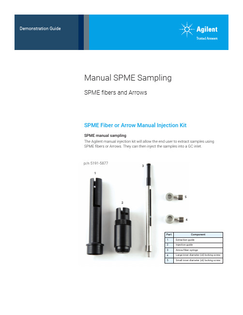
12345SPME Fiber or Arrow Manual Injection KitSPME manual samplingThe Agilent manual injection kit will allow the end user to extract samples using SPME fibers or Arrows. They can then inject the samples into a GC inlet.Manual SPME SamplingSPME fibers and Arrowsp/n 5191-58772PAL3 alignment ring (gray) for split/splitless (S/SL) inletManual injectionManual injection guidePAL3 alignment ring (Gray) for S/SL inlet (G7371-67001)The manual injection guide sits on thealignment ring for manual sample injection.3Methodology—manual samplingInstalling a PDMS SPME (100 μm) Arrow into the manual syringeLoosen the cap at the base of the syringe and remove it.Depress the black plunger completely.Screw the hub of an SPME fiber/Arrow into the bottom of the plunger at the end of thesyringe bodyRetract the black plunger and slide the cap over the SPME fiber/Arrow and tighten itonto the syringe.4The extraction guide has two positions where the syringe can be installed.The upper position is used for headspace extraction.The lower position is used for immersion extraction.Incorrect and correct position of the lower locking screw.Do not tighten the screw against the black plunger or you will not be able to move the SPME fiber/Arrow intoposition for sampling.Setting the locking screwsLarge inner diameter (id) locking screwSmall inner diameter (id) locking screwSlide the locking screws onto the syringe from the plunger side (the right side as shown above).• Install the large id locking screw onto the silver body of the syringe.• Install the small id locking screw onto the wider portion of the black plunger.•Tighten the locking screws until finger-tight. Do not overtighten, as they will be adjusted in later steps.5• Raise the syringe plunger to the fully extended position and insert the syringe and lower locking screw into the upper position of the extraction guide.•Lock the syringe into place by rotating it until the locking screw is positioned in the notch.• Adjust the syringe so that the SPME fiber/Arrow is protruding ~1 cm beyond the inner base of the extraction guide (A).• Tighten the lower locking screw securely.•The tip of the SPME fiber/Arrow will be recessed at least 1 mm in from the end ofthe extraction guide (B).A BSetting the locking screws for septum penetration depthPlace the extraction guide (with syringe in place) on a headspace sampling vial and loosen the upper locking screw.Adjust the SPME fiber/Arrow to the desired exposure depth by moving the black plunger.Choose a depth that ensures that the SPME fiber/Arrow will be in the gas phase.Once the SPME fiber/Arrow is at the proper depth, hold the plunger in place and slide the upper locking screw until it is flush against the top of the silver syringe body. Then tighten the upper locking screw securely.Setting the exposure depth for headspace extraction6Fine depth adjustment for direct immersion extractionAdjusting the injector penetration depthInsert the syringe into the lower position of the extraction guide.1. Manual SPME injection guide2. PAL3 alignment ring (gray) forS/SL inlet (G7371-67001)• Carefully insert the syringe into the injection guide.• Use caution to avoid damaging the SPME fiber/Arrow when threading it through the hole in the base of the injection guide.•Lock the syringe into place by rotating it until the locking screw is positioned in the notch.Penetrate a vial and fully expose the SPME fiber/Arrow within the vial.Adjust the lower locking screw and upper locking screw to obtain the desired exposure depth (to ensureimmersion in the sample liquid).127Setting injector penetration depthWith the appropriate GC-specific adaptor cup on the end of the injection guide, measure the distance from the tip of the SPME fiber/Arrow to the groove inside the adaptor cup.Adjust the desorption depth by screwing the body of the injection guide up or down (maximum depth = 67 mm).Twist the locking ring down until it locks on the body of the injection guide./chemDE.3985648148This information is subject to change without notice.© Agilent Technologies, Inc. 2020 Printed in the USA, March 6, 2020 5994-1732ENInjection onto the GC inletRemove the adapter cup from the injection guide.The adapter cup is placed onto the GC inlet to guide the manual injection.Push the plunger down until the top locking screw is resting on the body of the syringe.The sample is then injected.。

Hope Industrial Systems, Inc.User Manual15” Panel Mount Industrial MonitorRevision EModel Numbers: HIS-ML15- _ _ _ ETABLE OF CONTENTSSafety and Regulation Information (3)Factory Preset Timing (4)Setting the Timing Mode (5)OSD and Power Lock Settings (6)Adjusting the Screen Image (7)Main Menu Controls (9)Information for Resistive Touchscreen Monitors (13)Installation Instructions (14)Cleaning (16)Troubleshooting (17)Drawings (18)Specifications (20)Warranty Statement (23)2Safety and Regulatory InformationWarningTo prevent fire or shock hazard, do not expose the unit to rain or moisture. Dangerously high voltages are present inside the unit. Do not disassemble the unit. Refer servicing to qualified personnel only.This equipment is not intended for use in critical applications where its failure to operate would create immediate life threatening circumstances. Applica-tions including but no limited to nuclear reactor control, aerospace navigation systems and life support systems are not appropriate for this product.This product is intended to be mounted in a suitable cabinet or other enclosure. The NEMA 4, 4x or 12 ratings are applicable only when properly installed in a like rated enclosure.This product is a UL Recognized Component and must be used with a listed computer.FCC NoticeThis equipment has been tested and found to comply with the limits for a Class A digital device, pursuant to Part 15 of the FCC Rules. These limits are designed to provide reasonable protection against harmful interference when the equipment is operated in a commercial environment. This equipment generates, uses and can radiate radio frequency energy and, if not installed and used in accordance with the instruction manual, may cause harmful interference to radio communications. Operation of this equipment in a residential area is likely to cause harmful interference in which case the user will be required to correct the interference at his own expense. Any changes or modifica-tions not expressly approved by the grantee of this device could void the user’s authority to operate the device.3Factory Preset Timing* Factory recommended timings for best picture quality4Setting the Timing ModeSetting the computer’s timing mode is important for maximizing the quality of the screen image and minimizing eye strain. The timing mode consists of the screen resolution (ex. 1024 x 768) and the refresh rate (ex. 60 Hz or vertical frequency). After setting the computer’s timing mode, use the OSD (On Screen Display) controls to adjust the screen image.For the best picture quality set your LCD display timing mode to:1024 x 768 @ 60Hz.To set the timing mode on a computer running Microsoft Windows:1. Set the resolution: Right-click on the Windows desktop > Properties> Settings > adjust the resolution.2. Set the refresh rate: See your graphic card’s user guide for instruc-tions.Warning: Do not set the graphics card in your computer to exceed the maximum refresh rate of 75 Hz; doing so may result in permanent damage to your LCD display.5OSD and Power Lock SettingsOSD Lock:Press and hold the up arrow for 10 seconds. Locking theOSD disables the OSD buttons. If any buttons are pressed, the message OSD Locked will display for 5 seconds.OSD Unlock:Press and hold the up arrow again for 10 seconds.Power Button Lock:Locking the power button disables it. If the power button is pressed, the message Power Button Locked will display for 5 seconds. With or without this setting, after a power failure, your LCD display’s power will automatical-ly turn ON when power is restored.Press and hold the down arrow again for 10Power Button Unlock:seconds.67Adjusting the Screen ImageUse the buttons on the rear control panel to display and adjust the OSD controls which dis-play on the screen.81. To display the Main Menu, press button [1].Note: All OSD menus and adjustment screens disappear automatically after about 15 seconds. This is adjustable through the OSD timeout setting in the setup menu.2.To select a control to adjust, press or to scroll up or down in the Main Menu. 3. After the desired control is selected, press button [2]. A control screen like the oneshown below appears.4. To adjust the setting, press the up or downbuttons.5. To save the adjustments and exit the menu, press button [1] twice .The following tips may help optimize your display:• Adjust the computer’s graphics card so that it outputs a 1024 x 768 @ 60 Hz videosignal to the LCD display. (Look for instructions on “changing the refresh rate” in the graphics card’s user guide.)• If necessary, make small adjustments using H. POSITION and V. POSITION untilthe screen image is completely visible. (The black border around the edge of the screen should barely touch the illuminated “active area” of the LCD display.)9Main Menu ControlsAdjust the menu items shown below by using the up and downbuttons.Control ExplanationAuto Image Adjust automatically sizes, centers, and fine tunes the video signal to eliminate waviness and distortion. Press the [2] button to execute Auto Image Adjust.Note: Auto Image Adjust works with most common video cards. If this function does not work on your LCD display, lower the video refresh rate to60 Hz and set the resolution to its pre-set value.Contrast adjusts the difference between the image background (blacklevel) and the foreground (white level).Brightnessadjusts background black level of the screen image.Color Adjust provides several color adjustment modes, including preset color temperatures and a User Color mode which allows independent ad-justment of red (R), green (G), and blue (B). The factory setting for this product is 6500K (6500 Kelvin).10sRGB – This is quickly becoming the industry standard for color manage-ment, with support included in many of the latest applications. Enabling this setting allows the LCD display to more accurately display colors the way they were originally intended. Enabling the sRGB setting will cause the Contract and Brightness adjustment to be disabled.9300K – Adds blue to the screen image for cooler white (used in most of-fice settings with fluorescent lighting).6500K – Adds red to the screen image for warmer white and richer red.5400K – Adds green to the screen image for a darker color.User Color – Individual adjustments for red (R), green (G), and blue (B).1. To select color (R, G, or B) press button [2].2. To adjust selected color, press or .3. When all color adjustments are complete, press button [1] twice.Information displays the timing mode (video signal input) coming from the graphics card in the computer, the LCD model number, and the serial number. See your graphics card’s user guide for instruction on changing the resolution and refresh rate (vertical frequency).Note: VESA 1024 x 768 @ 60 Hz (recommended) means that the resolu-tion is 1024 x 768 and the refresh rate is 60 Hertz.H./V. Position (Horizontal/Vertical Position) moves the screen image left or right and up or down. Press button [[2] to toggle between Horizontal and Vertical. The Horizontal setting moves the screen image to the left or to the right. The Vertical setting moves the screen image up and down.H. Size (Horizontal Size) adjusts the width of the screen image.Fine Tune sharpens the focus by aligning text and/or graphics with pixel boundaries.Note: Try the Auto Adjust function before using the Fine Tune control.Sharpnessadjusts the clarity and focus of the screen image.Setup menu displays the menu shown below:Language Select allows the user to choose the language used in the me-nus and control screens. Resolution Notice advises the optimal resolution to use.OSD Position allows the user to move the on-screen display menus andcontrol screens.OSD Timeout sets the length of time the on-screen display screen is dis-played. For example, with a “15 second” setting, if a control is not pushedwithin 15 seconds, the display screen disappears.OSD Background allows the user to turn the On-Screen Display back-ground On or Off.Memory Recall returns the adjustments back to factor settings if the dis-play is operating in a factory Preset Timing Mode listed in the Specifica-tions of this manual.Information for Resistive Touchscreen MonitorsThe enclosed CD-ROM contains documentation and drivers for all major operating systems (touchscreen monitors only). To assure you have the most current information, check the following Internet addresses:/Touchscreen_Drivers.htmInstallation InstructionsPreparing for InstallationImportant! Perform the following steps BEFORE Installation of the monitor into the panel.1. Ensure that sufficient power is available.2. Ensure that sufficient space is available to allow for proper air flowinto and out of the unit.3. Ensure that the air temperature around the unit (top and bottom) willnot exceed the rated specifications of the unit.→The maximum rated temperature of the HIS-ML15 is 50°C (132°F)→Remember that heat rises – the temperature at the top of the cabinet will be much hotter than at the bottom whenthe air is not circulating.→Also, remember that even though this product is de-signed to operate at 50°C, the life span of any electronicdevice is shortened when it is consistently operated athigh temperatures. Therefore it is wise to take steps tokeep the temperature of the ambient air around the unitas low as possible.4. Ensure that the ambient humidity of the air around the unit does notexceed the rated specifications for the unit→The maximum rated humidity for the HIS-ML15 is 90% non-condensingInstallation into Panel1. Refer to the drawing below.2. Locate position in panel for mounting of the monitor. Assure thatthere is adequate space begin the panel. Allow extra space (0.5in. behind and on each side) for air ventilation.3. Cut a rectangular hole in the panel. Clean and deburr.Dimensions: 16.02” (406mm) W x 12.72” (323mm) H ; +/- .020”4. Separate the rear collar from the unit by removing the 12 nuts.5. Insert the unit into the front of the panel and re-attach the collar.6. Tighten all 12 nuts to a torque of 24 inch-pounds to assure a wa-ter-tight seal between the poron bezel gasket on the monitor andequipment panel. HIS will not assume liability for damage to in-ternal electronics due to improper installation.CleaningCAUTION! DO NOT USE ABRASIVE MATERIALS SUCH AS PAPER TOWELS OR DIRTY SHOP RAGS ON THE DISPLAY AS IT WILL SCRATCH THE PROTECTIVE COATING. ALWAYS USE A SOFT CLOTH, PREFERABLY MADE OF COTTON.Resistive Touchscreen modelAny standard glass cleaner can be used to clean the touch-screen. Always spray the glass cleaner on the cloth or toweland then clean the touchscreen. Glass cleaner sprayed di-rectly on the monitor could possibly leak inside a non-sealedunit and cause damage.Vinegar or ammonia will not hurt the touchscreen. Again, spray the cloth and then clean the touchscreen.Tempered Anti-Reflective Glass WindowUse any standard glass cleaner as long as there is no abrasive oroily content. The anti-reflective coatings are physically part of thesurface of the glass and resist degradation to the Military Specifica-tions.Acrylic BezelThe acrylic front bezel can be cleaned in the same manner as thetouchscreen or glass window.TroubleshootingBlank Screen After installing the power adapter and connecting I/O cable to a PC,the monitor displays a blank screen.•Press the power button and check to see if the power LED is lit.•If the LED turns green, make sure the PC is powered on.Make sure all cables are connected.•If the LED turns orange, check to see if the PC is in the powersaving mode by pressing any keys on the keyboard.Rolling Screen•Change PC display resolution to 1280x1024 at 60 Hz refresh.•Unplug the power adapter to monitor and then plug it in again.•Press monitor power button again.•Reset the monitor to the original factory setting.•Press “Auto” button.Unstable Screen•Press the “Auto” button.•Make sure the PC display resolution is not set greater than1024x768 at 60Hz.•Make sure the PC display resolution matches one of the facto-ry preset timings in this manual.•Change the PC display resolution to 1024x768 at 60hz.•Reset the monitor to the factory setting.•Press the “Auto” button.Screen is not perfect•Make sure the PC display resolution matches one the factorypreset timings shown in this manual.•Recall factory setting. Refer to panel controls and OSD func-tions in this manual.•Fine tune the picture by performing the following adjustmentsin this order – pitch, phase, and position. Refer to OSD func-tions in this manual.Auto Adjustment Locked•To unlock press the MENU and AUTO buttons simultaneouslyfor at least 5 seconds. (see page 7)DrawingsFront and Side ViewsRear View (Showing Cutout Dimensions)Rear and Bottom ViewsSpecificationsComplianceEnclosurePhysicalVGA Pin assignmentWarranty StatementWho is Covered?This warranty covers the purchaser of this product only and is not transferable without our written consent.What Does This Warranty Cover and What is the Period of Coverage?We warrant this product to be free from defects in material and workmanship, subject to the condi-tions set forth below. This warranty remains in force for a three-year period beginning on the date we invoice you for the product. If HIS repairs or replaces a product under warranty, its warranty term is not extended.What Will We Do to Correct Problems and How Do You Get Service?We will repair or replace (at our sole option) any part of the unit which proves to be defective. Re-placement parts may be new or refurbished and will meet the same specifications of the original parts or unit. We will return the product to you by the shipping method we choose in the U.S.A. at our expense. You must pay for shipments to locations outside of the U.S.A. In order to receive war-ranty service you must get prior approval from HIS. To request warranty service you can telephone ******************************************************.Ifwedeterminethatwarranty service is needed we will give you a Return Material Authorization (RMA) number. This RMA number must be conspicuously marked on the outside of the shipping box. HIS will not accept shipments not accompanied by the RMA number. You must ship or deliver the product to HIS Freight prepaid.What Does This Warranty Not Cover?This warranty does not cover equipment which has been damaged due to misuse, abuse or accident such as: operating the equipment outside of published specifications; displaying fixed images for long periods of time resulting in afterimage effects; improper or unauthorized repair by anyone other than HIS or a service agency authorized by HIS to perform such repairs; fire, flood, “acts of God”, or other contingencies beyond the control of HIS.HIS’ responsibility for malfunctions and defects in hardware is limited to repair and replacement as set forth in this warranty statement. HIS shall not be liable for direct, indirect, incidental, conse-quential, or other types of damages resulting from the use of any HIS product other than the liability stated above. These warranties are in lieu of all other warranties express or implied, including, but not limited to, the implied warranties of merchantability or fitness for a particular purpose. Some states do not allow the exclusion of implied warranties or the limitation or exclusion of liability for incidental or consequential damages so the above exclusions or limitations may not apply to you. You are cautioned that the performance of this product can be affected by many factors, such as sys-tem configuration, software, application, and operator control of the system. It is your responsibility to determine suitability of this product for your purpose and application.Hope Industrial Systems, Inc.1325 Northmeadow ParkwaySuite 100Roswell, GA 30076Publication UM-ML15E June, 2006 2006 Hope Industrial Systems, Inc.。

3-772CHEM-LABNV-BELGIUM-Tel.+32(0)50288320-Fax+32(0)*****************************.chem-lab.be4CHEM-LABNV-BELGIUM-Tel.+32(0)50288320-Fax+32(0)*****************************.chem-lab.beICP Single Element Standards 10 000 mg/LI C P S TA N D A R D S 10.000 P P MElement HNO 3HCl H 2ONH 4OHHFHNO 3/HF HNO 3/tart.KOHNaOHOthersAl CL01.0103CL01.0104Sb CL01.0123CL01.0124As CL01.0134Ba CL01.0203CL01.0204Be CL01.0214Bi CL01.0223B CL01.0233Cd CL01.0303Ca CL01.0314Ce CL01.0323Cs CL01.0333Cr CL01.0364CL01.0363Co CL01.1123CL01.1128Cu CL01.1133CL01.1134Dy CL01.0433Er CL01.0503Eu CL01.0513Gd CL01.0703Ga CL01.0713Ge CL01.0743Au CL01.0733Hf CL01.0804CL01.0803Ho CL01.0823In CL01.0923Ir CL01.0933Fe CL01.0903CL01.0904La CL01.1203Pb CL01.1223Li CL01.1214Lu CL01.1233Mg CL01.1304CL01.1310Mn CL01.1313Hg CL01.1153Mo CL01.1334CL01.1333Nd CL01.1413Ni CL01.1423Nb CL01.1433Pd CL01.1603P CL01.0643CL01.0633CL01.0634Pt CL01.1613K CL01.1104Pr CL01.1623Re CL01.1804CL01.1803Rh CL01.1813Rb CL01.1824Ru CL01.1834Sm CL01.1903Sc CL01.1913Se CL01.1923Si CL01.1943CL01.1934CL01.1933Ag CL01.2603Na CL01.1404Sr CL01.1963S CL01.2644CL01.2643Ta CL01.2003CL01.2004Te CL01.2015CL01.2014Tb CL01.2023Tl CL01.2033Th CL01.2043Tm CL01.2053Sn CL01.2063Ti CL01.2073CL01.2074W CL01.2303CL01.2304CL01.2333V CL01.2203Yb CL01.2503Y CL01.2513Zn CL01.2613ZrCL01.2633I C P S T A N D A R D SCHEM-LAB NV - BELGIUM - Tel. +32 (0)50 28 83 20 - Fax +32 (0)50 78 26 54 - info@chem-lab.be - www.chem-lab.be6AntimonyArsenicumBariumBerylliumBismuthBoronCadmiumCalciumCalcium oxideCeriumCesiumI C P S I N G L E E L E M E N T S CHEM-LABNV-BELGIUM-Tel.+32(0)50288320-Fax+32(0)*****************************.chem-lab.be7CobaltCopperDysprosiumErbiumEuropiumGadoliniumGalliumGermaniumGoldHafniumHolmium8CHEM-LABNV-BELGIUM-Tel.+32(0)50288320-Fax+32(0)*****************************.chem-lab.beIridiumIronLanthanumLeadLithiumLutetiumMagnesiumNEWMagnesium oxideManganeseMercuryMolybdenumNeodymiumI C P S I N G L E E L E M E N T S CHEM-LABNV-BELGIUM-Tel.+32(0)50288320-Fax+32(0)*****************************.chem-lab.be9NiobiumPalladiumPhosphorusPhosphorus pentoxidePlatinumPotassiumPotassium oxidePraseodymiumRheniumRhodiumRubidiumCHEM-LABNV-BELGIUM-Tel.+32(0)50288320-Fax+32(0)*****************************.chem-lab.be10SamariumScandiumSeleniumSiliciumSilverSodiumSodium oxideStrontiumSulfurTantalumTelluriumI C P S I N G L E E L E M E N T S CHEM-LABNV-BELGIUM-Tel.+32(0)50288320-Fax+32(0)*****************************.chem-lab.be11ThalliumThoriumThuliumTinTitaniumTungstenVanadiumYtterbiumYttriumZincZirconiumCHEM-LABNV-BELGIUM-Tel.+32(0)50288320-Fax+32(0)*****************************.chem-lab.be12A Certificate of Analysis is provided with each ICP standard stating:- Actual certified concentration of the final solution- Traceability to NIST- Expiration date- Trace impurities detected I C P S I NCHEM-LABNV-BELGIUM-Tel.+32(0)50288320-Fax+32(0)*****************************.chem-lab.be13ICP Single Element Standards 1 000 mg/LI C P S TA N D A R D S 1.000 P P MElement HNO 3HCl H 2ONH 4OHHFHNO 3/HF HNO 3/tart.KOH NaOHOthersAl CL01.0101CL01.0102Sb CL01.0121CL01.0122CL01.0162As CL01.0133CL01.0132CL01.0131Ba CL01.0201CL01.0202Be CL01.0212CL01.0211Bi CL01.0221B CL01.0232CL01.0231Cd CL01.0301Ca CL01.0311CL01.0312Ce CL01.0321Cs CL01.0331Cr CL01.0362CL01.0361CL01.0352Co CL01.1121CL01.1122Cu CL01.1131CL01.1132Dy CL01.0431Er CL01.0501Eu CL01.0511Gd CL01.0701Ga CL01.0711Ge CL01.0741CL01.0721Au CL01.0731Hf CL01.0802CL01.0801Ho CL01.0821In CL01.0921Ir CL01.0931Fe CL01.0901CL01.0902La CL01.1201CL01.1202Pb CL01.1221Li CL01.1212CL01.1211Lu CL01.1231Mg CL01.1301CL01.1302Mn CL01.1311CL01.1312Hg CL01.1151Mo CL01.1332CL01.1331Nd CL01.1411Ni CL01.1421CL01.1422Nb CL01.1431Os CL01.1501Pd CL01.1601P CL01.0641CL01.0631Pt CL01.1611K CL01.1101CL01.1102Pr CL01.1621Re CL01.1802CL01.1801Rh CL01.1811Rb CL01.1822CL01.1821Ru CL01.1831Sm CL01.1901Sc CL01.1911Se CL01.1922CL01.1921Si CL01.1999CL01.1945CL01.1932CL01.1931CL01.1935Ag CL01.2601Na CL01.1401CL01.1402Sr CL01.1962CL01.1961S CL01.2641CL01.2642Ta CL01.2001CL01.2002Te CL01.2012CL01.2013CL01.2011Tb CL01.2022Tl Th CL01.2041Tm CL01.2051Sn CL01.2061CL01.2062Ti CL01.2072CL01.4601CL01.2071CL01.2075W CL01.2302CL01.2301CL01.2331V CL01.2201Yb CL01.2501Y CL01.2511Zn CL01.2611CL01.2612ZrCL01.2632CL01.2631CL01.2672I C P S I N G L E E L E M E N T S T A N D A R D SCHEM-LAB NV - BELGIUM - Tel. +32 (0)50 28 83 20 - Fax +32 (0)50 78 26 54 - info@chem-lab.be - www.chem-lab.be14Aluminium(III) oxideAntimonyArsenicumBariumBerylliumBismuthBoronCadmiumI C P S I N G L E E L E M E N T S CHEM-LABNV-BELGIUM-Tel.+32(0)50288320-Fax+32(0)*****************************.chem-lab.be15Calcium oxideCeriumCesiumChromiumCobaltCopperDysprosiumErbiumEuropiumGadoliniumGalliumCHEM-LABNV-BELGIUM-Tel.+32(0)50288320-Fax+32(0)*****************************.chem-lab.be16GoldHafniumHolmiumIndiumIridiumIronIron(III) oxideLanthanumLeadLithiumLutetiumI C P S I N G L E E L E M E N T S CHEM-LABNV-BELGIUM-Tel.+32(0)50288320-Fax+32(0)*****************************.chem-lab.be17Magnesium oxideManganeseManganese(III) oxideMercuryMolybdenumNeodymiumNickelNiobiumOsmiumPalladiumDon’t see the exact solution you need?E-mail us the Tailor Made Standard Quotation request form in the back of the catalog. 18CHEM-LABNV-BELGIUM-Tel.+32(0)50288320-Fax+32(0)*****************************.chem-lab.bePhosphorus pentoxidePlatinumPotassiumPotassium oxidePraseodymiumRheniumRhodiumRubidiumRutheniumSamariumScandiumI C P S I N G L E E L E M E N T S CHEM-LABNV-BELGIUM-Tel.+32(0)50288320-Fax+32(0)*****************************.chem-lab.be19SiliciumSilicium dioxideSilverSodiumSodium oxideStrontiumSulfurTantalumCHEM-LABNV-BELGIUM-Tel.+32(0)50288320-Fax+32(0)*****************************.chem-lab.be20TerbiumThalliumThoriumThuliumTinTitaniumTungstenVanadiumYtterbiumI C P S I N G L E E L E M E N T SZincZirconiumLuis BianchiISO/IEC 17025:2005 - General requirements for the competence of calibration laboratories ISO 9001:2008 - Quality ManagementISO Guide 34:2009 - General requirements for the competence of reference material producers A Certificate of Analysis is provided with each ICP standard stating:- Actual certified concentration of the final solution - Traceability to NISTAntimonyArsenicumBariumBerylliumBoronCadmiumCalciumCeriumCesiumChromiumCobaltCopperDysprosiumErbiumI C P S I N G L E E L E M E N T SGadoliniumGalliumGermaniumGoldHafniumHolmiumIndiumIridiumIronLanthanumLeadLithiumLutetiumManganeseMercuryMolybdenumNeodymiumNickelNiobiumOsmiumPalladiumPhosphorusPlatinumPotassiumPraseodymiumRheniumRhodiumI C P S I N G L E E L E M E N T SRutheniumSamariumScandiumSeleniumSiliciumSilverSodiumSulfurTantalumTelluriumTerbiumThalliumThoriumThuliumTinTitaniumTungstenVanadiumYtterbiumYttriumZincZirconium NEWDon’t see the exact solution you need?I C P S I N G L E E L E M E N T SAluminiumAntimonyBariumBerylliumBismuthBoronCadmiumCalciumCeriumCesiumChromiumCobaltCopperDysprosiumEuropiumGadoliniumGalliumGermaniumGoldHafniumHolmiumIndiumIridiumIronLanthanumLeadI C P S I N G L E E L E M E N T SLutetiumMagnesiumManganeseMercury NEWMolybdenumNeodymiumNickelNiobiumOsmiumPalladiumPhosphorusPlatinumPotassiumPraseodymiumRhodiumRubidiumRutheniumSamariumScandiumSeleniumSiliciumSilverSodiumSulfurTantalumTelluriumTerbiumThalliumI C P S I N G L E E L E M E N T SThuliumTinTitaniumTungstenVanadiumYtterbiumYttriumZincZirconium NEWChem-Lab’s certified “Custom Made Standards” will save you time and money.Multi Element ICP QC Standard sol. (QCS-23) (23E)CL01.13610Multi Element ICP QC Standard sol. (QCS-01) (23E)CL01.13601I C P M U L T I E L E MMulti Element ICP QC Standard sol. (QCS-04) (19E)NEW CL01.13604Multi Element ICP QC Standard sol. (QCS-19) (19E)CL01.13608Multi Element ICP QC Standard sol. (QCS-02) (7E)CL01.13602Multi Element ICP ASL QC Standard sol. (QCS-ASL-7) (7E)CL01.13607Multi Element ICP QC Standard sol. (QCS-06) (4E)CL01.13606I C P M U L T I E L E MA Certificate of Analysis is provided with each ICP standard stating:- Actual certified concentration of the final solution- Traceability to NIST- Expiration date- Trace impurities detectedMulti Element ICP SQS Standard sol. (SQS-01) (33E)CL01.13631I C P M U L T I E L E MReference Materials - Contents of certificates and labelsGeneral requirements for the competence of calibration laboratoriesPage 2 of 2Chem-Lab multi-element standards are compared against the following NIST SRMs Element Aq. SRMOil SRMElement Aq. SRMOil SRMAg 31511077a Nb 3137-Al 3101a 1075a Nd 3135a -As 3103a 3103a Ni 31361065b Au 3121-NO3-3185-B 31073107NO2-136e -Ba 3104a 1051b P 3139a 1071b Be 3105a 3105a Pb 31281059c Bi 31063106Pd 3138-Br-3184-PO4-33186-Ca 3109a 3109Pr 3142a -Cd 31081053a Pt 3140-Ce 3110-Rb 3145a -Cl-919b -Re 3143-Co 31133113Rh 3144-Cr 3112a 1078b S 31543154Cs 3111a -Sb 3102a 3102a Cu 31141080a Sc 3148a 3148a Dy 3115a -Se 31493149Er 3116a -Si 31501066a Eu 3117a -Sm 3147a -F-3183-Sn 3161a 1057b Fe 3126a 1079b SO4-23181-Ga 3119a -Sr 3153a 1070a Gd 3118a -Ta 3155-Ge 3120a -Tb 3157a -Hf 3122-Te 3156-Hg 31333133Th 3159-Ho 3123a -Ti 3162a 3162a In 3124a -Tl 31583158K 3141a 3141a Tm 3160a -La 3127a 3127a U 3164-Li 3129a 1060a V 31651052b Lu 3130a -W 3163-Mg 3131a 3131a Y 3167a 3167a Mn 31323132Tb 3166a -Mo 31343134Zn 3168a 1073b Na3152a1069bZr31693169*ICP-EPA Methods (Method 200.7 Version 3.3 & earlier) - Laboratory Performance Check Standard (LPCS) Contains 29 elements in 5% HNO3Multi Element ICP LFSS Standard sol. LFSS-01 (25E)CL01.13772*ICP-EPA Methods (Method 200.7 Version 3.3 & earlier) - Laboratory Fortifying Stock Solution (LFSS) Contains 25 elements in 5% HNO3 + traces HFMulti Element ICP SP Standard sol. SP-03 (12E)CL01.13743I C P M U L T I E L E*ICP-EPA Methods (Methods 6010A - 6010B - 200.7 Version 3.3 and earlier) - Mixed Calibration Standard 1 Contains 6 elements in 2% HNO3 (MCS-Multi Element ICP CAL Standard sol. MCS-04 (6E)CL01.13734Multi Element ICP SP Standard sol. SP-05 (5E)CL01.13745Multi Element ICP CAL Standard sol. MCS-02 (5E)CL01.13732 *ICP-EPA Methods (Methods 6010A - 6010B - 200.7 Version 3.3 and earlier) - Mixed Calibration Standard 2 Contains 5 elements in 2% HNO3 (MCS-Multi Element ICP SP Standard sol. SP-05R (5E)CL01.13754*ICP-EPA Methods (Method 200.7 Version 3.3 and earlier) - Spiking Standard for Drinking Water # 5R Contains 5 elements in 5% HNO3 (M-200.7-SP-Multi Element ICP SIC Standard sol. SICS-02 (5E)CL01.13762Multi Element ICP PLASOL Standard sol. M-200.7-PLASOL-1 (4E)CL01.13723*ICP-EPA Methods (Method 200.7 Version 4.4, May 1994) - Plasma Solution (PLASOL) - Determining optimum viewing height of the plasma analytical zone.I C P M U L T I E L E MMulti Element ICP SP Standard sol. SP-01R (4E)CL01.13751 *ICP-EPA Methods (Method 200.7 Version 3.3 and earlier) - Spiking Standard for Drinking Water # 1R Contains 4 elements in H2O + traces HF (M-Multi Element ICP SP Standard sol. SP-02R (4E)CL01.13752 *ICP-EPA Methods (Method 200.7 Version 3.3 and earlier) - Spiking Standard for Drinking Water # 2R Contains 4 elements in 2% HNO3 (M-200.7-SP-Multi Element ICP CAL Standard sol. MCS-03 (3E)CL01.13733Tailor Made Mixtures can be formulated to meet your special applications.Multi Element ICP SP Standard sol. SP-01 (3E)CL01.13741Multi Element ICP TUNSOL Standard sol. M-200.7-TUNSOL-1 (2E)CL01.13724*ICP-EPA Methods (Method 200.7 Version 4.4, May 1994) - Tuning Solution (TUNSOL) - Adjusting the aerosol argon gas flow prior to calibration and analysis.Mono Element ICP SP Standard sol. TCLP-02 (1E)CL01.13773*ICP-EPA Methods (Methods 6010B - 200.7 Version 3.3 and earlier) - Spiking & Mercury Standard - TCLP Standaard 2 Contains 1 elements in 5%I C P M U L T I E L E MMono Element ICP SP Standard sol. SP-04R (1E)CL01.13753 *ICP-EPA Methods (Method 200.7 Version 3.3 and earlier) - Spiking Standard for Drinking Water # 4R Contains 1 elements in 2% HNO3 (M-200.7-SP-Mono Element ICP SIC Standard sol. SICS-01 (1E)CL01.13761Mono Element ICP SP Standard sol. TCLP-02-10X (1E)CL01.13746*ICP-EPA Methods (Method 200.7 Version 4.4, May 1994) - Instrument Fortifying (Spiking) Standard # 1 Contains 26 elements in 5% HNO3 + tracesMulti Element ICP IPC Standard sol. M-200.7-IPC-01 (26E)CL01.13721 *ICP-EPA Methods (Method 200.7 Version 4.4, May 1994) - Instrument Performance Check (IPC) Contains 26 elements in 5% HNO3 (M-200.7-IPC-I C P M U L T I E L E*ICP-EPA Methods (Method 200.7 Version 4.4, May 1994) - Instrument Fortifying (Spiking) Standard for Solids # 1 Contains 24 elements in 5% HNO3Multi Element ICP LFSS Standard sol. M-200.7-LFSS-01W (22E)CL01.13712 *ICP-EPA Methods (Method 200.7 Version 4.4, May 1994) - Instrument Fortifying (Spiking) Standard for Water # 1 Contains 22 elements in 5% HNO3Multi Element ICP CAL Standard sol. M-200.7-01 (10E)CL01.13701Chem-Lab’s certified “Custom Made Standards” will save you time and money.Multi Element ICP CAL Standard sol. M-200.7-02R (6E)CL01.13702Multi Element ICP LFSS Standard sol. M-200.7-LFSS-02 (5E)CL01.13714*ICP-EPA Methods (Method 200.7 Version 4.4, May 1994) - Instrument Fortifying (Spiking) Standard # 2 Contains 5 elements in 5% HNO3 + traces HFMulti Element ICP IPC Standard sol. M-200.7-IPC-02 (5E)CL01.13722*ICP-EPA Methods (Method 200.7 Version 4.4, May 1994) - Instrument Performance Check (IPC) Contains 5 elements in 5% HNO3 + traces HF (M-I C P M U L T I E L E MMulti Element ICP PLASOL Standard sol. M-200.7-PLASOL-1 (4E)CL01.13723 *ICP-EPA Methods (Method 200.7 Version 4.4, May 1994) - Plasma Solution (PLASOL) - Determining optimum viewing height of the plasma analytical zone.Multi Element ICP CAL Standard sol. M-200.7-03R (4E)CL01.13703Multi Element ICP TUNSOL Standard sol. M-200.7-TUNSOL-1 (2E)CL01.13724 *ICP-EPA Methods (Method 200.7 Version 4.4, May 1994) - Tuning Solution (TUNSOL) - Adjusting the aerosol argon gas flow prior to calibration and analysis.Multi Element ICP QC Standard sol. (QCS-01) (23E)CL01.13601Multi Element ICP INT Standard sol. INT-B1 (12E)CL01.13682I C P M U L T I E L E MMulti Element ICP QC Standard sol. (QCS-02) (7E)CL01.13602Multi Element ICP CAL Standard sol. MCS-01 (6E)CL01.13731 *ICP-EPA Methods (Methods 6010A - 6010B - 200.7 Version 3.3 and earlier) - Mixed Calibration Standard 1 Contains 6 elements in 2% HNO3 (MCS-Multi Element ICP Standard sol. PLASOL-R (5E)CL01.13822A Certificate of Analysis is provided with each ICP standard stating:- Actual certified concentration of the final solution- Traceability to NIST- Expiration date- Trace impurities detected。

NOT MEASUREMENTSENSITIVEMIL-C-81706AMENDMENT 623 October 2000SUPERSEDINGINT. AMENDMENT 5(AS)13 November 1979AMENDMENT 410 March 1977MILITARY SPECIFICATIONCHEMICAL CONVERSION MATERIALS FOR COATINGALUMINUM AND ALUMINUM ALLOYSThis amendment forms a part of MIL-C-81706, dated 30 June 1970, and is approved for use by all Departments and Agencies of the Department of Defense.PAGE 11.2.2.1: Add:“Form IV – Premixed liquid, thixotropic (ready for use)Form V – Premeasured powder, thixotropic (ready for use after addition of water) *Form VI –Premixed liquid (ready for touch-up use in self-contained applicatordevice).”PAGE 2* 1.2.2.2: Add:“Method D – Applicator pen.”* 2.1: Under SPECIFICATIONS, Federal delete:“L-B-560 Bottle, Screw Cap (Polyethylene)TT-P-143Paint, Varnish, Lacquer, and Related Materials, Packaging, Packing,and Marking of.”AMSC N/A 1 of 7AREA MFFP DISTRIBUTION STATEMENT A. Approved for public release; distribution is unlimited.* 2.1: Under SPECIFICATIONS, Federal add:“PPP-P-1892-Paint, Varnish, Lacquer, and Related Materials; Packaging,Packing and Marking of2.1: Under SPECIFICATIONS, Military add:*“MIL-B-26701 - Bottle, Polymer, in a Combination Container, Shipping andStorage, Air Eligible (Inactive for new design)*MIL-PRF-85285 - Coating, Polyurethane, High-Solids*MIL-PRF-85582 - Primer Coatings: Epoxy, Waterborne*Change “MIL-P-23377” to “MIL-PRF-23377.”PAGE 3*Add new paragraph:“2.2Non-Government publications. The following documents form a part of this document to the extent specified herein. Unless otherwise specified, the issues of the documents that are DoD adopted are those listed in the issue of the DoDISS cited in the solicitation. Unless otherwise specified, the issues of documents not listed in the DoDISS are the issues of the documents cited in the solicitation (see 6.2).AMERICAN SOCIETY FOR TESTING AND MATERIALS (ASTM)ASTM-D3359-Standard Test Methods for Measuring Adhesion by Tape Test(Application for copies should be addressed to the American Society for Testing and Materials, 100 Barr Harbor Drive, West Conshohocken, PA 19428-2959.)”* 3.4: Delete the first sentence and substitute:“3.4 Application. The material, when furnished in the form specified in 1.2.2.1, after proper mixing, shall allow treatment of the prepared metal in accordance with the supplier’s instructions, by spray, brush, immersion, or ready-to-use applicator pen. The applicator pen solution shall not be permitted to puddle.”PAGE 4* 3.4: Add to end of paragraph “Form IV and V films shall show an average weight of 2.8 to 6.5 grams of material adhering to panels tested in accordance with the method specified in 4.5.7.The material shall cling uniformly with no visual evidence of excessive run-off or lack of film coverage.”*Table I: Add “1/” after “336.”*Table I: At end of table add “1/ Exposure time for Class 1A, Form VI, Method D materials shall be 168 hours.”PAGE 4*Add new paragraph:“3.7.3 Adhesion (wet tape) after repair (Class 1A, Form VI, Method D only). After panel repair and immersion specified in 4.5.8, the scribed panels shall exhibit no peel away and be rated at not less than 4A in accordance with ASTM-D3359. There shall be no blistering of the unscribed coated area.”PAGE 5* 3.10, delete the first sentence and substitute: “Materials conforming to this specification shall have a storage life of not less than 12 months.”PAGE 64.3.2, line 5: Delete: “five gallons” and substitute “eight one-quart bottles.”* 4.3.2, line 7: After “(see 5.2.1).” add “For Class 1A, Form VI, Method D material,the supplier shall furnish 12 applicator pens.”* 4.3.3, line 6: After “width” add “, except those required for wet tape adhesion (panels 12 through 29) shall be 5 inches in length”PAGE 7After 4.3.3.1, add new paragraph:“4.3.3.1.1 Panel preparation for adherence test. Three, 3 x 10 x 0.032 inch panels of 7075-T6 aluminum alloy shall be cleaned with toluene followed by acetone (3 x 0.032 inch x any length over 4 inches may be used). The panels shall then be marked with a pencil line 4 inches from one end. Each clean, marked panel shall be placed in a separate 600 ml beaker and weighed with the beaker to the nearest tenth of a gram.”* 4.3.3.2: Delete and substitute:“4.3.3.2 Panel treatment for class 1A material. Panels of each alloy, lettered “A” and “B”detailed, marked, and cleaned in accordance with 4.3.3 and 4.3.3.1 shall be treated as follows:Class 1A, Form VI, Method D Panels – Panels shall be treated on one side by the qualifying activity in accordance with the supplier’s instructions. All panels shall be dried at ambient conditions for 24 hours before finishing or testing. Panels marked 1 through 5 shall have edges protected by wax or other standard method.All other panels – Panels shall be treated by the qualifying activity on all surfaces in accordance with the supplier’s instructions. All panels shall be dried between 70 and 90 °F (21 and 32 °C) for 24 hours before finishing or testing, except those to be used for coating weight.”4.3.3.3: Delete and substitute:“4.3.3.3 Panel finishing for class 1A material. The A and B lettered panels numbered 7 through 29in accordance with 4.3.3 shall be finished as follows:Class 1A, Form VI, Method D (Panels 7 and 8) – Panels shall be finished with one coat of an epoxy primer conforming to MIL-PRF-23377 or MIL-PRF-85582. Panels shall be air dried for 14 days before testing.Class 1A, Form VI, Method D (Panels 12 through 20) – Panels shall be finished with one coat of epoxy primer conforming to MIL-PRF-23377 followed by, after the primer has dried, a polyurethane topcoat conforming to MIL-PRF-85285. Panels shall be air dried for 14 days before testing.Class 1A, Form VI, Method D (Panels 21 through 29) – Panels shall be finished with one coat of epoxy primer conforming to MIL-PRF-85582, followed by, after the primer has dried, a polyurethane topcoat conforming to MIL-PRF-85285. Panels shall be air dried for 14 days before testing.All other panels – Panels shall be finished as specified in 4.3.3.3.1.”PAGE 8*Table II, under Class 1A Panel Nos., after “7 to 8” add “and 12 to 29.”*Table II, under Reference paragraphs, after 4.5.3, add “and 4.5.8.”*Table II, under Requirement paragraphs, after “3.7.2” add “3.7.3.”*Table II, footnote 1/, after “respectively.” Add “Panels 12 through 29 are only required for Class 1A, Form VI, Method D materials.”*Table II, under Tests, after “Coating Weight” add ‘‘6/.”*Table II, under footnote 5/, add footnote “6/ Class 1A, Form VI, Method D materials are not subjected to coating weight test.”PAGE 9* 4.3.4.1, at end of paragraph add: “Class 1A, Form VI, Method D materials shall not undergo weight of film testing.”Insert new paragraph after 4.3.6:“4.3.7 Retention of qualification. In order to retain qualification of a product approved for listing on the Qualified Products List (QPL), the manufacturer shall verify by certification to the qualifying activity, that the manufacturer’s product complies with the requirements of this specification. Unless otherwise specified, the time of periodic verification by certification shall be in two-year intervals from the date of the original qualification, and shall be initiated by the qualifying activity. No change shall be made in formulation, raw materials or supplier(s) of raw materials, methods of manufacture, equipment, or geographic location without prior written Government approval. The Government reserves the right to re-examine the qualified product whenever deemed necessary to determine that the product continues to meet any or all of the specification requirements.”PAGE 11*Table III, under Test, after “Coating Weight” add ‘‘2/.”*Table III, under footnote 1/, add footnote “2/ Class 1A, Form VI, Method D materials shall not be subjected to coating weight test.”PAGE 13Add new paragraphs after 4.5.6:“4.5.7 Vertical adherence test. In addition to the other tests required for class 1A materials, Form IV and Form V shall be tested for ability to adhere to a vertical surface as specified in 3.4.4.5.7.1 Material preparation. One quart of the Form IV or Form V material (with required water added) shall be thoroughly mixed and allowed to stand for 24 hours. Transfer enough of the material to almost fill a 600 ml plastic beaker.4.5.7.2 Adherence. Each previously prepared panel, in accordance with 4.3.3.1.1, shall be immersed, one at a time, in the coating material up to the 4 inch pencil line, lifted vertically above the surface of the material and allowed to drain for 45 seconds. The panel shall then be transferred without rinsing to the beaker in which it was originally weighed and the beaker and the coated panel shall be re-weighed to the nearest tenth of a gram.4.5.7.3 Weight of material clinging. The weight of material clinging to the panel is equal to the original weight of the panel plus the beaker subtracted from the weight of the panel plus the coating plus the beaker. Average weight determined from the three tests shall conform to 3.4.”PAGE 13*Add new paragraphs:“4.5.8 Adhesion (wet tape) after repair (Class 1A, Form VI, Method D only).4.5.8.1 Repair procedure. Panels 12 through 29 finished as specified in 4.3.3.3 shall be abraded to a shiny substrate using a Scotch Brite wheel (see 6.8). The remainder of the topcoat shall be lightly abraded to accept refinish primer. The abraded area shall be 4 square inches. Class 1A, Form VI, Method D material shall be applied to the abraded panel and conditioned in accordance with the manufacturer’s instructions. The entire surface of panels 12 through 20 and 21 through 29 shall be refinished as specified in the appropriate section of 4.3.3.3.4.5.8.2 Immersion procedure. Painted panels shall be immersed in distilled water as follows:3 panels of each substrate and finish for 24 hours at room temperature.3 panels of each substrate and finish for 96 hours at 120°±2 °F (49°±1 °C).3 panels of each substrate and finish for 168 hours at 150°±2 °F (65.5°±1 °C). Upon completion of the immersion period, the panels shall be removed from the water, dried using a clean, dry soft cloth, and be immediately evaluated as specified in 4.5.8.3.4.5.8.3 Evaluation procedure. Each panel shall be evaluated in accordance with Method A of ASTM-D3359 except for the following:a.There shall be one “X” scribed incisions between parallel lines that are approximately 1inch apart. All incisions shall be into the substrate. The scribed area shall include theoriginal paint, overlap area, and the repair area.b.The tape, 3M Type 250 (see 6.8), shall be placed on the panel parallel to the parallelscribed lines and be smoothed by rolling a 3 pound roller over it once. Tape removal shall be as specified in ASTM-D3359.c.The incision areas shall be inspected for peel away and the unscribed areas for blistering.Conformance to 3.7.3 shall be required.”PAGE 175.2: Delete “Specification TT-P-143” and substitute: “PPP-P-1892.”5.2.1, fourth sentence: Delete and substitute “Polyethylene bottles with polyethylene screw cap closures, conforming to MIL-B-26701, shall be used for packaging of premixed liquids for touch up brush application and for powder in quantities of 5 pounds or less.”5.2.1, line 8: Delete “(see6.2)” and substitute “and the premeasured powder shall be packaged in one quart quantities with the bottle marked with the powder level and the added liquid level (see 6.2).”PAGE 18* 6.1.1: Add to end of paragraph “Class 1A, Form VI, Method D materials covered by this specification are intended for use in the formation of chemical conversion coatings for repair or touch-up applications which are corrosion preventative and improve adhesion of paint finish systems to aluminum and aluminum alloys.”PAGE 19* 6.3.2, line 1: After “(Method B)” add “and pen application (Method D).”* 6.8 Source of tape. Type 250 tape and Scotch Brite wheels are available for purchase from the 3M Company, Minneapolis, MN.NOTE: The margins of the amendment are marked with an asterisk to indicate where changes from the previous amendment were made. This was done as a convenience only and the Government assumes no liability whatsoever for any inaccuracies in these notations. Bidders and contractors are cautioned to evaluate the requirements of the document based on the entire content irrespective of the marginal notations and relationship to the last previous issue. Custodians:Preparing activity:Army – MR Navy – ASNavy – ASAir Force – 99(Project MFFP-0674)Review activities:Army – AR, AT, MINavy – OS, SHAir Force – 11Other – DS。

1729674-1Portable Crimp Tools, Premium Crimp Tooling, Not Releasable, Not Adjustable,Fixed In Tool, TE Product Specification (114-), Certification, ManualApplication Tooling>Portable Crimp ToolsCertification:YesSpecification Type:TE Product Specification (114-)Die Sets Type:Fixed In ToolRatchet Configuration:Not Releasable, Not AdjustableTool Grade:Premium Crimp ToolingFeaturesOtherCrimp Form-Wire Barrel Type Open Barrel - F CrimpTool Grade Premium Crimp ToolingRatchet Configuration Not Releasable, Not AdjustableDie Sets Type Fixed In ToolSpecification Type TE Product Specification (114-)Certification YesPower Type ManualTool Type Straight Action Hand ToolProduct ComplianceFor compliance documentation, visit the product page on >EU RoHS Directive 2011/65/EU Out of ScopeEU ELV Directive 2000/53/EC Out of ScopeChina RoHS 2 Directive MIIT Order No 32, 2016Not reviewed for China RoHS complianceEU REACH Regulation (EC) No. 1907/2006Current ECHA Candidate List: JUN 2020(209)Candidate List Declared Against: JUN 2016(169)Does not contain REACH SVHC 1729674-1 ACTIVEAMPTE Internal #:1729674-1Portable Crimp Tools, Premium Crimp Tooling, Not Releasable,Not Adjustable, Fixed In Tool, TE Product Specification (114-),Certification, ManualView on >Halogen Content Not Yet Reviewed for halogen content Solder Process CapabilityNot applicable for solder process capabilityProduct Compliance DisclaimerThis information is provided based on reasonable inquiry of our suppliers and represents our current actual knowledge based on the information they provided. This information is subject to change. The part numbers that TE has identified as EU RoHS compliant have a maximum concentration of 0.1% by weight in homogenous materials for lead, hexavalent chromium, mercury, PBB, PBDE, DBP, BBP, DEHP, DIBP, and 0.01% for cadmium, or qualify for an exemption to these limits as defined in the Annexes of Directive 2011/65/EU (RoHS2). Finished electrical and electronic equipment products will be CE marked as required by Directive 2011/65/EU. Components may not be CE marked.Additionally, the part numbers that TE has identified as EU ELV compliant have a maximum concentration of 0.1% by weight in homogenous materials for lead, hexavalent chromium, and mercury, and 0.01% for cadmium, or qualify for an exemption to these limits as defined in the Annexes of Directive 2000/53/EC (ELV). Regarding the REACH Regulations, TE’s information on SVHC in articles for this part number is still based on the European Chemical Agency (ECHA) ‘Guidance on requirements for substances in articles’(Version: 2, April 2011), applying the 0.1% weight on weight concentration threshold at the finished product level. TE is aware of the European Court of Justice ruling of September 10th, 2015 also known as O5A (Once An Article Always An Article) stating that, in case of ‘complex object’, the threshold for a SVHC must be applied to both the product as a whole and simultaneously to each of the articles forming part of its composition. TE has evaluated this ruling based on the new ECHA “Guidance on requirements for substances in articles” (June 2017, version 4.0) and will be updating its statements accordingly.TE Model / Part #3-1633860-2CRIMPER, WIRE FTE Model / Part #2836262-1OCEAN_2.0_Applicator-S-O42F070OVTE Model / Part #936887-00222759/33-26-7TE Model / Part #2-1579021-8CSV10 4.2 ConnSystTE Model / Part #1437000-9779-2151=DIE 622 FEM SKT USE WTE Model / Part #615571-00222759/33-26-5TE Model / Part #45160DAHT PG 22-16TE Model / Part #66102-2III+ PIN,24-20,TIN-LEAD,STRIPTE Model / Part #CAT-G7534-T111GRACE INERTIA TabTE Model / Part #CAT-G7534-R2435GRACE INERTIA ReceptacleCompatible PartsCustomers Also BoughtTE Model / Part #CB5371-000SST-48-15/FR/97/NMDocumentsProduct DrawingsSAHT FOR GIC 6.2MM PITCH W-W CONTACT L JapaneseDatasheets & Catalog PagesCrimp Term Whitepaper-Use the Right Tool 1-1773953-1 EnglishCRIMPING WHERE FORM MEETS FUNCTION EnglishBottoming DiesEnglishProduct SpecificationsGRACE INERTIA CONNECTOR 6.2MM PITCH JapaneseApplication SpecificationJapanese。

Supplier's guide for product developmentPart 2-core processes 20© Volkswagen, 1446, Konzern-EntwicklungssteuerungSupplier's guide for product development2.1 Procurement processA main focus of the present guide are subjects which are from the point of view of the technical development for new suppliers within the scope of the product development of the biggest meaning. An introduction to processes relevant for suppliers and applications which lie in the area of responsibility of the procurement also counts to it.2.1.1 introductionThe procurement of the Volkswagen group is split in the ranges of Procurement for production material and general procurement. The range of Procurement for production material is made up again of the Commodities displayed in illustration 11.Illustration 11: Overview of the different ranges of the procurementProcurement decisions become short in the Volkswagen group of the Corporate Sourcing Committee (: CSC) grieved. The decisions of this committee are valid about all marks away.Beside the central procurement ranges of every mark the Volkswagen group seats so-called regional shopping offices (RSO = On the regional level Sourcing of office) to open new procurement markets and to upgrade passing ones. Illustration 12 makes clear the present activities of regional procurement offices worldwide.© Volkswagen, 1446, Konzern-Entwicklungssteuerung21Procurement for production materials: parts and components forthe vehicleGeneral Procurement: resources, production of good and services for theproduction processresources, services and systemsProjectPurchasing & Buying Parts Managementmetalinteri orexteriorElectric al & Electron icsSupplier's guide for product developmentRegional offices (Ros) Lander assignmentCentral Europe Eastern EuropeNorth Africa Turkey IndiaIllustration 12: Regional procurement offices of the Volkswagen group worldwide2.1.2 Division of the procurement processesWith the choice and nomination of group suppliers two different procurement processes play a role. These are:❑ Forward Sourcingfor parts to be produced and newly to be developed. This process is used in general with developmentprojects for new vehicles or aggregates❑ Worldwide Sourcingfor the already existing parts manufactured after drawing which should be procured at the respectivemarket locally. The destination of this process is to create market transparency, to optimise thelogistics costs as well as to improve the quality of standard parts.For new ones as well as for standard parts a worldwide inquiry and assignment strategy occurs.The division of the procurement processes is displayed in illustration 13 figuratively.22© Volkswagen, 1446, Konzern-EntwicklungssteuerungSupplier's guide for product developmentIllustration 13: Division of the procurement processes2.1.3 Component procurement in the product process of developmentIn principle two different process attempts are used in the Volkswagen group with Forward Sourcing and Worldwide Sourcing for the component procurement. The temporal classification of these processes in the product life cycle makes clear illustration 14.Illustration 14: Differentiation between Forward Sourcing and Worldwide Sourcing processThe Forward Sourcing process is used with new projects and is linked up to the market launch (ME) with the so-calledpurchase part management process. This process being based on the gate principle makes sure that suppliers are able with manufacturing beginning (SOP = start of Production) to deliver the concerning extents in the respective number of pieces or quality what reduces the project risk again.© Volkswagen, 1446, Konzern-Entwicklungssteuerung23For new parts in existing models in new modelsFor existing share in existing models in new models (carry-over parts)Supplier of highperformance of unit and subsequent production ResponsibilitySupplier with lessdevelopment content as reproducer and / or second applicant for partial volume.before commercial launch After commercial launchForward Sourcing (new parts)Purchased PartsManagement- Forward SourcingGlobal Sourcing (existing components) Purchased PartsManagement-Global Sourcingsupplier information and offersupplier SelectionOf the Worldwide Sourcing process, however, is used only after the market launch of a product and isaccompanied by a suitable purchase part management process with different gates. You find closer information to the purchase part management process for Forward Sourcing and Worldwide Sourcing in chapter 2.5 "Purchase part management".Forward Sourcing processThe procurement process for suppliers in development projects encloses basically three phases displayed in illustration 15.Illustration 15: Phases of the Forward Sourcing of processPhase 1 - Supplier Self-Disclosure and offerThe Volkswagen group determines potential suppliers on the basis of themSupplier Self-Disclosure (LSA). The Volkswagen group transmits to the supplier the inquiry documents (also inquiry package called) on basis more technically, more financially, organizational as well as qualitative demands. The supplier edits these documents and as a result transmits his offer to theVolkswagen group. The suppliers who have received an inquiry must fancy in this phase, besides, with the suitable development department. Besides, the presentation should contain information todeveloping competence and available technologies. The template of pattern parts has turned out in this connection as especially helpful. The contact data of the concerning development department can be taken from the inquiry documents.24 © Volkswagen, 1446, Konzern-EntwicklungssteuerungSupplier Profile and offerSupplier selectionapproval process for Forward Sourcing -suppliers list-Registration on Group Business Platform-Supplier Self-Disclosure -preselection for inquiry -Request to supplier -range of Volkswagen-Presentation of the technical concept in the technical development-TE-Audit-process Audit -Suppliers decision -notification about nomination-kick-off event -SET-work-Purchase Parts Management-Component clearancesproduction releaseSupplier nominated and the beginning of the development process as a first supplierHit Supplier ScreeningTip: With the establishment of contact with the range of Development the supplier should take care with the respective development department proactively of the exhibition of a suitable secrecy arrangement.The arrangement itself is edited about the department of Te of service / office (departmental abbreviation / G).Phase 2 - supplier's choiceThe results of the supplier's judgment with which the abilities (Te and process audit) and capacities of a supplier are determined flow in onto the decision of the group to the nomination of component suppliers. At the end of the ability judgment the supplier receives the classification A, B or C and for a nomination atleast the classification B is necessary. Suppliers with the classification B are obliged to put up anoperation plan with improvement measures. After successful qualification a renewed audit is carried out.An overview about the contents of both audits gives illustration 16.Illustration 16: Overview about the contents of the Te and process audit in the supplier's choiceThe final procurement decisions of the Volkswagen group are based on the one hand on the entries of all partners and, on the other hand, on strategically considerations as well as on the competitiveness of the submitted offers. On this occasion, is to be mentioned that all procurement decisions are madeunanimously.Phase 3 - release process for Forward SourcingIn this phase the Volkswagen group monitors the capacity of the supplier within the respective project.For main components the process of the purchase part management is applied. Besides, are seated to so-called gates - measuring dots for the capacity classification of the supplier - and releases specific for component are monitored. The single gates are closely connected with vehicle landmarks. Developing releases can be thereby traced and it can be guaranteed, that the pattern parts for the respective one© Volkswagen, 1446, Konzern-Entwicklungssteuerung25Landmark are delivered. The purchase part management process becomes short from so-called purchase part management-teams (: KTM teams) monitored and controlled. These consist of representatives of different function ranges and are responsible for the following dots:❑ Realization of regular project talks ❑ Sequential monitoring of the supplier.Global Sourcing processThe procurement process for suppliers within the scope of the Worldwide Sourcing corresponds Extensively to that of the Forward Sourcing:Illustration 17: Phases of the Global Sourcing processPhase 1 - Supplier Self-Disclosure and offerPhase 1 corresponds to that of the Forward Sourcing process. Phase 2 - supplier's choiceThe second phase also corresponds to that of the Forward Sourcing process, howeverif begins after the nomination a process in whose course the supplier industrializes the component for manufacturing and develops as a second developer on the basis of available function and construction space default.26 © Volkswagen, 1446, Konzern-EntwicklungssteuerungSupplier Self-Disclosure and offerSupplier selection Purchased Parts Management Global Sourcing-Registration on Group Business Platform-Supplier Self-Disclosure -Preselection for inquiry -Request to supplier -Range of Volkswagen -Presentation of the technical concept in the technical development-TE-audit-process Audit -suppliers decision -Notification about nomination-kick-off event-Commitmentconversation-Purchased Parts Management -component clearances Hit Supplier ScreeningSupplier nominated and thebeginning of the industrialization process as a second supplierproduction releaseSupplier's guide for product developmentPhase 3 - release process for Global-SourcingThis phase resembles the purchase part management for the Forward Sourcing process.Nevertheless, differences arise with the definitions of the single gates as well as with the kind of the goods to be delivered or results of working (e.g., pattern and prototype). With projects within the scope of the Worldwide Sourcing of process gates Reviews - the final evaluations are attached by reaching of a gate - not to vehicle landmarks, but in between the supplier and the KTM team of agreed appointments.2.1.4 Group business platform and registration processThe Volkswagen group uses the group to business platform to communicate in every phase of a vehicle project with his suppliers. Started with the registration process about the offer delivery up to the pursuit of landmarks and pattern states - the group business platform forms the central turntable for the communication with all organisations of the Volkswagen group with her integrated applications.Illustration 18: Group business platform of the Volkswagen groupTip: On the group business platform there are for every range (e.g., procurement, quality assurance, development) special applications for suppliers. One or several should the applications called in this guide not be available to you, you must let this only about the B2B activate team.© Volkswagen, 1446, Konzern-Entwicklungssteuerung27SuppliersVolkswagen GroupGroup Business PlatformWorldwideinformation and communication hubB2B portalSupplier's guide for product developmentYou reach the B2B team at the following address:b2bteam@the contact data of the B2B of team you find in the range "Help" of herGroup business platform. Illustration 19 shows the range "Help" on the platform and offers an example of integrated applications.Illustration 19: Integrated applications to the group business platformRegistration processHow already in chapter 2.1.3 "Component procurement in the product process of development"described, new suppliers must go through a registration process in the first phase of the procurement process. The first part of the registration on the group business platform forms the so-called Supplier Self-Disclosure which become by choice of the button "Partner!" it is launched. The data transmitted within the scope of the Supplier Self-Disclosure are checked in the second step by the B2B team on correctness. If the data are correct, the B2B switches team the suppliers for the third and last step of the registration process freely. To conclude the registration, now the supplier must enter additional information on the supplier's data bank of the Volkswagen group. Finally the B2B user agreement must be accepted and be set up a Company administrator on the platform. The whole registration process is summarized into illustration 20.28© Volkswagen, 1446, Konzern-EntwicklungssteuerungB2B portalSupplier's guide for product developmentIllustration 20: Registration process for the group business platform (abstract)© Volkswagen, 1446, Konzern-Entwicklungssteuerung29Part 1: Become a partnerPart 2: Data ReviewPart 3: additional informationvisit:and click on the link "Become a Partner""Partners will" click on the link "Start Supplier Questionnaire" and they fill up the formData receive Confirmation and assignment of a registration numberReview of supplier self-assessment by the SITCreating the user record, the initial password registrar obtaining a user ID and for Initial registration in the protected area of the B2Bsupplier platformElectronic confirmation of the B2B User AgreementCreating a user profile for the Company Administratorin UMSCompany information incl. DUNS numberRegistration Numbertest successfulThe B2B AGREEMENT must Moreover, within 6 weeks in the original signed will be sent toVolkswagen.B2B portalSupplier's guide for product developmentYou find closer information to the registration process on the login page the group business platform:→Do you select "partner become"→"The registration process " and afterwards "Supplier Self-Disclosure start". On the left screen page a description of the registration process is available in the PDF format to the download.2.1.5 Supplier Self-DisclosureAs already in chapter 2.1.3 "Component procurement in the product process of development" described, new suppliers must go through a so-called Supplier Self-Disclosure in the first phase of the procurement process. The forms necessary for it - in Volkswagen also LSA forms called - are made available by the buyer responsible for component. The satisfactory form offers to Volkswagen the first overview about the product portfolio of the supplier, available technologies, present customers (e.g., animal one, animal two), the organizational structure (e.g., technical arrangements, joint-ventures) as well as about capacities and the respective capacity spectrum (e.g., quality assurance, development).Illustration 21: LSA formTip: The LSA form is to be filled very completely. Only so is made sure that inquiries are sent by the procurement to possible suppliers.Supplier's guide for product development2.1.6 Information specific for development in the inquiry packageThe destination of the first phase of the procurement process (supplier's information / offer) is to be decided it whether a supplier comes to the narrower choice. The offer delivery on the part of the supplier occurs online about the application "Online Requests (ESL)" (ESL: Electronic Supplier link) on the group business platform. Click on the following icon to access this application:Illustration 22: The application "Online-Anfragen (ESL)" to the group business platformOffers are specific for project and specific for component. The supplier must guarantee that all aspects find consideration concerning the used technology, the production procedure and the load notebook standards on offer. The procurement of the Volkswagen group can make sure by the fact that all offers are comparable. However, the supplier can make sure with the fact that no important and information possibly relevant for price is absent to the respective component.Illustration 23 shows the inquiry overview with the different inquiry kinds in the application "ESL".List of sent requestsIllustration 23: Inquiry overview in ESLInquiry kind Every component is requested separately. These inquiries (also RFQ or Request for Quotation) are also specific for vehicle and are divided into Global Sourcing inquiries and Forward Sourcing inquiries. You find closer information to both procurement processes in chapter 2.1.2 "Division of the procurement processes". In the inquiry list both inquiry kinds can be distinguished with the help of the abbreviations fa for Forward Sourcing and G for Global Sourcing.Contacts for every part are fixed by different ranges involved in the respective development project of Contact. These are also performed in every inquiry and are to be consulted with questions to the inquiry documents.Contents relevant for development of the inquiry package The inquiry packages relevant for development (compressed in the ZIP format) are marked in illustration 24 and must be considered in the offer delivered by the suppliers.3.Offer SpecificDocuments1. Volkswagen brand2. Volkswagen GroupSpecific inquiry ContactIllustration 24: Contact information of a selected inquiry package and contents relevant for developmentOf inquiry package1) Looks at documents specific for offer from the position of the product development, this package containsall essential, information on offer to be considered to the component requested in each case.The typical contents of such a package are performed in the following:❑ Component-load notebook (briefly: BT-LAH or LH) with closer information to himto respective developing standards (e.g., marginal conditions concerning the component or project,used technology, test standards and project management directives)Illustration 25: Component-load notebook❑ Reference drawingIllustration 26: Reference drawing as a basis for the offer❑ Draught responsibility arrangement (KV rate)Purpose of the so-called draught responsibility rate (briefly: KV rate) it is to fix the responsibilites of theparties by the development of components, modules and systems already early obligingly. With theKV rate it concerns a value specific for component which is agreed on basis of the draughtresponsibility arrangement by agreement. Further information about this subject is demonstrated inchapter 2.1.10 "Bases to the draught responsibility arrangement".2) Mark of Volkswagen The second package encloses demands specific for mark and objectives which must be considered on offer:❑ Procurement: Shopping conditions on the procurement of production material❑ Quality: Agreed high-class ability destination.3) Volkswagen group - research & developmentThe first and package to be downloaded by the suppliers on offer to be considered contains information to the following subjects relevant for product development:❑ Volkswagen group norm VW99000 "general demands toCapacity performance within the scope of the component development" see also chapter 2.1.9"juridical arrangements and their influence on technical drawings", chapters 2.2 "of The ProductDevelopment Process of the Volkswagen group" as well as chapters 2.3 "Approval processeswithin the Product Development Process "❑Supplier's manual for prototypesSee also chapter 2.7 "Prototype drawee processes and demands"❑Supplier's guide for product development (this document)❑Manufacturer's password for vehicle parts❑Template part curriculum vitae.2.1.7 Norm data bank of the Volkswagen groupDemands for e.g. components, (Raw) materials, testing methods as well as to the supply of data and components are described in the Volkswagen group with the help of internal norms.To this it is refered in technical drawings as well as in the component-load basting contained in the inquiry package. Illustration 27 shows such a reference.Illustration 27: Reference to covalid norms on technical drawingsIt must be guaranteed by all developing suppliers, that to the project themto in each case actual versions of the norms to be applied are available. This isSupplier's guide for product developmentin particular during the nomination process of meaning, because only is so guaranteed that the offer encloses all demands for components and check.The in each case actual versions of the suitable norms can be downloaded into several languages directly by the group business platform.The application necessary for it called "online norm texts" the group business platform is available to you in the range "information" under the menu dot "Tools". By clicking the following icon you reach directly to the application:In the application "online norm texts (ONNO)" can be seen following norm kinds and be downloaded: ❑Volkswagen group factory Standard – VW❑Technical condition of delivery – TL❑Test instruction – PV❑Technical guideline documentation – TLD❑Construction directive – KR❑High-class specification – QP❑Norm part drawings - N / SDL.The action with the search for norms in the application "online norm texts" is displayed in illustration 30. Norms and directives are published into different languages which are indicated by the suitable land flags. Check after appearance of the hit list which is the in each case actual version of the document.Besides, the application "online norm texts" offers the button Extents about which itself a list of norms specific for project gets which can be downloaded then at regular intervals equem.Tip: Should the application "online norm texts" on the group business platform not be indicated, get in contact please with the B2B team to apply for access. You find the contact data of the SIT in chapter 2.1.4 "Group business platform and registration process".Supplier's guide for product development Illustration 28: Application "online norm texts" on the group business platformSupplier's guide for product development2.1.8 Norm parts and repeated hasteWith all new projects norm haste and repeated haste are to be used mainly from the Volkswagen group norm VW60000 "variation reduction of connection elements". If the part spectrum is not described yet, the parts are short exclusively from the norm part administration system (: To use NVS) of the Volkswagen group. In the norm part administration system information is administered to norm parts, half witnesses and fuels.In addition, are also offered repeated haste of the group. All hyperkV-users also have in the partner company net the access privileges for the NVS (HyperKVS: see chapter 2.9.5 "surgical data interchange").With parts with limited release consultation with the department representatives of the principal (see contacts in the national carriage group norm VW60000) is necessary. The demands of the Volkswagen group norm VW60457 are valid "mechanical connection elements for mechanical connection elements; Requirement profile thread parts".Tip: A localisation of norm - or Repeat parts is to be tuned, in any case, with the release places of the Volkswagen group.2.1.9 Juridical arrangements and their influence on technical drawingsAmong the rest, the Volkswagen group norm VW99000 "general demands to the capacity performance within the scope of the component development" contains demands of juridical kind. With acceptance of this group norm the supplier (or contractor) accepts the juridical arrangement described in it.On this occasion, chapter 2.5 "juridical arrangements" of the Volkswagen group norm VW99000 is to be followed especially. Demands for the data to be provided by the suppliers (e.g., technical drawings) arise from this chapter again. From suppliers submitted offers must enclose the supply of data which may be used by the Volkswagen group in unlimited measure.The suppliers are informed during the procurement process of the responsible buyer about this demand. With nomination these circumstances are held on in a written arrangement. In this connection is to be pointed out to chapter 2.5.5.3 Copyrights of the Volkswagen group norm VW99000.Tip: To avoid civil disputs after the nomination, the Volkswagen group norms VW99000 are "general demands to the capacity performance within the scope of the component development "und VW01058" drawings; to work through inscriptions" from the supplier carefully and completely.38© Volkswagen, 1446, Konzern-EntwicklungssteuerungB2B portalSupplier's guide for product development2.1.10 Bases to the draught responsibility arrangementThe draught responsibility arrangement (briefly: KVV) divides itself into the end of a principle arrangement KVV and into the individual portion of the supplier in the technical draught of a component. The acknowledgement of the KVV by the supplier is a requirement for the assignment of a new part.The portion of the supplier in the technical draught is expressed about the KV rate and is directed after the developing depth requested by the suppliers. Inclusively is valid: the less constructive default by the Volkswagen group, the higher is the KVV portion. The definition of the KV rate by the designer responsible for component takes place in the early draught phase of a new part development and is a component of the inquiry documents (see chapter 2.1.6 "information specific for development in the inquiry package").Following classifications of the KV rates are valid it:❑ series suppliers (low developing depth):KV rate 10%❑ Standard developer ("middle" developing depth):KV rate 30 - 70%❑Draught developer (high developing depth):KV rate 90%As mentioned above the arrangements with KVV are valid for all new parts, are excluded here: ❑ Raw parts❑ Norm parts❑ Company means❑ Process materialYou find further information about the subject draught responsibility arrangement in the range "information" of the business division "Quality assurance" on the group business platform under following link:© Volkswagen, 1446, Konzern-Entwicklungssteuerung39B2B portalSupplier's guide for product development2.1.11 LION - supplier's part information onlineWith LION (supplier's part information online) it concerns an online application. Their main focus lies on the communication between supplier and the Volkswagen group during the preseries phase and initial phase. LION enables to suppliers to retrieve data specific for component from data banks of the Volkswagen group and to update these data independently.LION offers:❑ Actual, clear and standardised exchange of information betweento the Volkswagen group and his suppliers❑ Less redundant inquiries and with it a lowering of the costs forCommunication and coordination❑ Reduction of the treatment expenditure, by manual data inputthere originates and thereby less input error.LION encloses different modules which are used as a function of the project progress. Duties are assigned for each of the part numbers for which he was nominated automatically to the supplier. Such duties are, e.g.: ❑ Listing of pattern appointments and supplier's contact data(LION module "part appointments" and "contact data")❑ Documentation of the part generation and the part curriculum vitae(LION module "part generation state care")❑ Documentation of Reviews and tool appointment pursuit betweenSuppliers and organisations of the Volkswagen group (LION module "CoRe" - Commitment Reviews) The application "LION" is available after occurred registration by the B2B support on the group business platform and can be called by choice of the following icon:Illustration 29 shows how you can access LION.。

Association for the Advancement of Medical Instrumentation协会中文名称:AAMI;美国医疗器械促进协会1 AAMI 7198-1998 (R 2004) CARDIOVASCULAR IMPLANTS - TUBUAL VASCULAR PROSTHESES-FDA RECOGNIZED2 AAMI 10993-1-2003 Biological evaluation of medical devices - Part 1: Evaluation and testing-FDA RECOGNIZED3 AAMI 10993-2-2006 Biological evaluation of medical devices - Part 2: Animal welfare requirements4 AAMI 10993-3-2003 Biological Evaluation of Medical Devices, Part 3: Tests for Genotoxicity, Carcinogenicity and Reproductive Toxicity5 AAMI 10993-4-2002 Biological evaluation of medical devices - Part 4: Selection of tests for interaction with blood-Incorporates Amendment 1: 20066 AAMI 10993-5-1999 BIOLOGICAL EVALUATION OF MEDICAL DEVICES, PART 5: TEST FOR IN VITRO CYTOTOXICITY-FDA RECOGNIZED7 AAMI 10993-6-1995 (R 2001) BIOLOGICAL EVALUATION OF MEDICAL DEVICES, PART 6: TESTS FOR LOCAL EFFECTS AFTER IMPLANTATION-FDA RECOGNIZED8 AAMI 10993-7-1995 (R 2001) Biological Evaluation of Medical Devices, Part 7: Ethylene Oxide Sterilization Residuals-Only FDA RECOGNIZED if used in conjunction to AAMI TIR19: 1988; Replaces AAMI ST29: 1988 and AAMI ST30: 1989 [Use: AAMI TIR19 AMD 1]9 AAMI 10993-9-1999 (R 2005) Biological evaluation of medical devices - Part 9: for identification and quantification of potential degradation products10 AAMI 10993-11-2006 Biological evaluation of medical devices - Part 11: Tests for systemic toxicity11 AAMI 10993-12-2002 Biological evaluation of medical devices - Part 12: Sample preparation and reference materials-FDA RECOGNIZED12 AAMI 10993-13-1999 (R 2004) Biological evaluation of medical devices, Part 13: Identification and quantification of degradation products from polymeric devices.13 AAMI 10993-14-2001 (R 2006) BIOLOGICAL EVALUATION OF MEDICAL DEVICES, PART 14: IDENTIFICATION AND QUANTIFICATION OF DEGRADATION PRODUCT FROM CERAMICS14 AAMI 10993-15-2000 (R 2006) Biological evaluation of medical devices?Part 15: Identification and quantification of degradation products from metals and alloys15 AAMI 10993-16-1997 (R 2003) BIOLOGICAL EVALUATION OF MEDICAL DEVICES - PART 16: TOXICOKINETIC STUDY DESIGN FOR DEGRADATION PRODUCTS AND LEACHABLES FROM MEDICAL DEVICES16 AAMI 10993-17-2002 BIOLOGICAL EVALUATION OF MEDICAL DEVICES, PART17: ESTABLISHMENT OF ALLOWABLE LIMITS FOR LEACHABLE SUBSTANCES17 AAMI 11135 ERTA-2005 Medical devices ?Validation and routine control of ethylene oxide sterilization-Erratum issued: 20 January 1995 (print copy only) and Erratum issued: 6 April 2005 (PDF copy only)18 AAMI 11135-1994 Medical devices - Validation and routine control of ethylene oxide sterilization-FDA RECGOGNIZED; esignations: AAMI OPEO, AAMI ST27, and AAMI TIR1 [Refer to: AAMI TIR14, AAMI TIR15, AAMI TIR16, AAMI TIR20, AAMI TIR28]19 AAMI 11137-1-2006 Sterilization of health care products - Radiation - Part 1: Requirements for the development, validation and routine control of a sterilization process for medical devices-Also replaces AAMI ST31, AAMI ST32, AAMI TIR520 AAMI 11137-3-2006 Sterilization of health care products - Radiation - Part 3: Guidance on dosimetric aspects-Also replaces AAMI ST31, AAMI ST32, AAMI TIR521 AAMI 11138-1-2006 Sterilization of health care products - Biological indicators - Part 1: General requirements [Refer to: AAMI 18472] 22 AAMI 11138-2-2006 Sterilization of health care products - Biological indicators - Part 2: Biological indicators for ethylene oxide sterilization processes [Refer to: AAMI 18472]23 AAMI 11138-3-2006 Sterilization of health care products - Biological indicators - Part 3: Biological indicators for moist heat sterilization processes [Refer to: AAMI 18472]24 AAMI 11138-4-2006 Sterilization of health care products - Biological indicators - Part 4: Biological indicators for dry heat sterilization processes [Refer to: AAMI 18472]25 AAMI 11138-5-2006 Sterilization of health care products - Biological indicators - Part 5: Biological indicators for low-temperature steam and aldehyde sterilization processes [Refer to: AAMI 18472]26 AAMI 11607-2-2006 Packaging for terminally sterilized medical devices - Part 2: Validation requirements for ing, sealing and assembly processes27 AAMI 11737-2-1998 Sterilization of Medical Devices - Microbiological Methods - Part 2: Tests of Sterility Per ed in the Validation of a Sterilization Process-FDA RECOGNIZED28 AAMI 13485-2003 Medical devices - Quality management systems - Requirements for regulatory purposes29 AAMI 14155-1-2003 Clinical investigation of medical devices for human subjects - Part 1: General requirements30 AAMI 14155-2-2003 Clinical investigation of medical devices for human subjects?Part 2: Clinical investigation plans31 AAMI 14160-1998 Sterilization of Single-Use Medical Devices Incorporating Materials of Animal Origin - Validation and Routine Control of Sterilization by Liquid Chemical Sterilants-FDA RECOGNIZED32 AAMI 14161-2000 Sterilization of health care products?Biological indicators?Guidance for the selection, use, and interpretation of results-FDA RECOGNIZED33 AAMI 14937-2000 Sterilization of health care products?General requirements for characterization of a sterilizing agent and the development, validation, and routine control of a sterilization process for medical devices-FDA RECOGNIZED34 AAMI 15223-2000 Medical Devices - Symbols to be used with medical device labels, labeling and in ation to be supplied.-FDA RECOGNIZED; Includes Amendment 1: 11/5/2001 and Amendment 2: 4/23/200435 AAMI 15225-2000 (R 2006) NOMENCLATURE - SPECIFICATION FOA A NOMENCLATURE SYSTEM FOR MEDICAL DEVICES FOR THE PURPOSE OF REGULATORY DATA EXCHANGE-Includes Amendment 1: 200436 AAMI 15674-2001 Cardiovascular implants and artificial organs —Hard shell cardiotomy/venous reservoir systems (with/without filter) and soft venous reservoir bags37 AAMI 15675-2001 Cardiovascular implants and artificial organs?Cardiopulmonary bypass systems?Arterial blood line filters38 AAMI 15882-2003 Sterilization of health care products - Chemical indicators - Guidance for selection, use, and interpretation of results-FDA RECOGNIZED39 AAMI 17665-1-2006 Sterilization of health care products - Moist heat - Part 1 Requirements for the development, validation and routine control of a sterilization process for medical devices- er Designation: AAMI ST2540 AAMI 25539-1 AMD 1-2005 Cardiovascular implants - Endovascular devices - Part 1: Endovascular prostheses, Amendment 1: Test methods 41 AAMI 25539-1-2003 Cardiovascular implants?Endovascular devices?Part 1: Endovascular prostheses42 AAMI 60601-2-21-2000 Medical electrical equipment, Part 2: Particular requirements for the safety of infant radiant warmers-FDA RECOGNIZED; er Designation: AAMI II52; Incorporates Amendment 1: 2000 43 AAMI 62304-2006 Medical device software - Software life cycle processes [Refer to: AAMI TIR32]44 AAMI BE78-2002 BIOLOGICAL EVALUATION OF MEDICAL DEVICES, PART 10: TEST FOR IRRITATION AND DELAYED TYPE HYPERSENSITIVITY-In place of AAMI 10993-10; FDA RECOGNIZED45 AAMI BE83-2006 Biological evaluation of medical devices - Part 18: Chemical characterization of materials46 AAMI BF7-1989 (R 2002) Blood Transfusion Micro-Filters-FDA RECOGNIZED47 AAMI BF64-2002 LEUKOCYTE REDUCTION FILTERS48 AAMI 7199-1996 (R 2002) Cardiovascular implants and artificial organs - Blood-ga* **changers (oxygenators)49 AAMI BP22-1994 (R 2006) Blood Pressure Transducers-FDA RECOGNIZED; Incorporates Errata: 08/05/200450 AAMI 5840-2005 Cardiovascular implants - Cardiac valve prostheses-FDA RECOGNIZED51 AAMI DF80-2003 Medical electrical equipment, Part 2: Particular requirements for the safety of cardiac defibrillators [including automated external defibrillators]-Also repalces AAMI TIR252 AAMI EC11-1991 (R 2001) Diagnostic electrocardiographicdevices-FDA RECOGNIZED53 AAMI EC12-2000 (R 2005) Disposable ECG Electrodes-FDA RECOGNIZED54 AAMI EC13 ERTA-2002 Cardiac Monitors, Heart Rate Meters and Alarms55 AAMI EC13-2002 Cardiac Monitors, Heart Rate Meters and Alarms56 AAMI EC38-1998 Ambulatory Electrocardiographs-FDA RECOGNIZED57 AAMI EC53 ERTA-2001 ECG cables and leadwires-Includes Erratum issued: 31 May 199858 AAMI EC53-1995 (R 2001) ECG cables and leadwires59 AAMI EC57-1998 (R 2003) Testing and reporting per ance results of cardiac rhythm and ST segment measurement algorithms-Includes Errata: 4/14/2004; Revision of ECAR: 1987; FDA-Recognized60 AAMI EC71-2001 Standard Communications Protocol - Computer Assisted Electrocardiography-Proposed equivalency to IEC60601-2-53/Ed.1: Harmonized61 AAMI EQ56-1999 (R 2004) Recommended practices for a medical equipment management program62 AAMI ES60601-1-2005 Medical electrical equipment, Part 1: General requirements for basic safety and essential per ance63 AAMI HE48-1993 Human Factors Engineering Guidelines and Preferred Practices for the Design of Medical Devices64 AAMI HE74-2001 Human Factors Design Process for MedicalDevices-FDA RECOGNIZED65 AAMI HFMD-1996 An Introduction to Human Factors in Medical Devices66 AAMI ID26 ERTA-2006 Medical electrical equipment, Part 2: Particular requirements for the safety of infusion pumps and controllers 67 AAMI ID54-1996 (R 2005) Enteral Feeding Set Adapters and Connectors-FDA RECOGNIZED68 AAMI NS4-1986 (R 2002) Transcutaneous Electrical Nerve Stimulators69 AAMI NS14-1995 (R 2002) Implantable spinal cord stimulators70 AAMI NS15-1995 (R 2002) Implantable peripheral nerve stimulators71 AAMI NS28-1988 (R 2006) Intracranial Pressure Monitoring Devices-FDA RECOGNIZED; Incorporates Errata: 06/200172 AAMI PAC49-1993 (R 2000) Pacemaker Emergency Intervention System73 AAMI PB70-2003 LIQUID BARRIER PER ANCE AND CLASSIFICATION OF PROTECTIVE APPAREL AND DRAPES INTENDED FOR USE IN HEALTH CAREFACILITIES-FDA RECOGNIZED74 AAMI PC69-2000 ACTIVE IMPLANTABLE MEDICAL DEVICES ELECTROMAGNETIC COMPATIBILITY EMC TEST PROTOCOLS FOR IMPLANTABLE CARDIAC PACEMAKERS AND IMPLANTABLE CARDIOVERTER DEFIBRILLATORS75 AAMI RD5-2003 Hemodialysis Systems76 AAMI RD16 AMD 1-2002 (R 2005) Hemodialyzers-FDA RECOGNIZED77 AAMI RD16-1996 (R 2005) Hemodialyzers [Refer to: IEC 60601-2-16]78 AAMI RD17-1994 (R 2005) Hemodialyzer Blood Tubing-Includes Amendment 1: 200279 AAMI RD47-2002 Reuse of Hemodialyzers-Incorporates Amendment 1: 7/2003 and Errata: 07/200380 AAMI RD52-2004 Dialysate for hemodialysis81 AAMI RD62-2006 WATER TREATMENT EQUIPMENT FOR HEMODIALYSIS APPLICATIONS82 AAMI SP10-2006 Manual, electronic, or automated sphygmomanometers-FDA REGOGNIZED; Incorporates Amendment 1: 2003; Amendment 2: 200683 AAMI ST8-2001 Hospital Steam Sterilizers-FDA RECOGNIZED84 AAMI ST24-1999 (R 2005) Automatic, General-Purpose Ethylene Oxide Sterilizers and Ethylene Oxide Sterilant Sources Intended for Use in Health Care Facilities-FDA RECONIZED85 AAMI ST40-2004 Table-top dry heat (heated air) sterilization and sterility assurance in health care facilities-FDA RECOGNIZED86 AAMI ST41-1999 (R 2005) Ethylene Oxide Sterilization in Health Care Facilities: Safety and Effectiveness-FDA RECOGNIZED87 AAMI ST50-2004 Dry Heat (Heated Air) Sterilizers-FDA RECOGNIZED88 AAMI ST55-2003 Table-Top Steam Sterilizers-FDA RECOGNIZED89 AAMI ST63-2002 Sterilization of health care products—Requirements for the development, validation, and routine control of an industrial sterilization process for medical devices—Dry heat-FDA RECOGNIZED90 AAMI ST65-2000 PROCESSING OF REUSABLE SURGICAL TEXTILES FOR USE IN HEALTH CARE FACILITIES91 AAMI ST66-1999 STERILIZATION OF HEALTHCARE PRODUCTS - CHEMICAL INDICATORS - PART 2 : CLASS 2 INDICATORS FOR AIR REMOVAL TEST SHEETS AND PACKS-FDA RECOGNIZED [Refer to: AAMI 18472]92 AAMI ST67-2003 Sterilization of health care products—Requirements for products labeled “STERILE?FDA RECOGNIZED93 AAMI ST77-2006 Containment devices for reusable medical device sterilization94 AAMI ST81-2004 Sterilization of medical devices - In ation to be provided by the manufacturer for the processing of resterilizable medical devices-FDA RECOGNIZED95 AAMI TIR4-1989 Apnea Monitoring by Means of Thoracic ImpedancePneumography96 AAMI TIR11-2005 Selection and use of protective apparel and surgical drapes in health care facilities97 AAMI TIR12-2004 Designing, Testing and Labeling Reusable Medical Devices for Reprocessing in Health Care Facilities: A Guide for Device Manufacturers-2nd Edition98 AAMI TIR13-1997 Principles of Industrial Moist HeatSterilization-(Updated material from ANSI/AAMI ST25:1987 )99 AAMI TIR14-1997 Contract Sterilization for EthyleneOxide-Updated material from AAMI ST27; Cited by FDA as "relevant guidance" for ANSI/AAMI/ISO 11135: 1994; Includes Amendment 1: 2004 [Refer to: AAMI 11135 ERTA]100 AAMI TIR15-1997 Ethylene Oxide Sterilization Equipment, Process Considerations and Pertinent Calculations-Updated material from AAMI ST27; Cited by FDA as "relevant guidance" for ANSI/AAMI/ISO 11135: 1994 [Refer to: AAMI 11135 ERTA]101 AAMI TIR16-2000 PROCESS DEVELOPMENT AND PER ANCE QUALIFICATION FOR ETHYLENE OXIDE STERILIZATION - MICROBIOLOGICAL ASPECTS-Updated material from AAMI ST27; Cited by FDA as "relevant guidance" forANSI/AAMI/ISO 11135: 1994 [Refer to: AAMI 11135 ERTA]102 AAMI TIR17-1997 Radiation Sterilization MaterialQualification-Cited by FDA as "relevant guidance" for ANSI/AAMI/ISO 11137: 1994; Replaces AAMI ST32 [Refer to: AAMI 11137]103 AAMI TIR18-1997 Guidance on Electromagnetic Compatibility of Medical Devices for Clinical/Biomedical Engineers - Part 1: Radiated Radio-Frequency Electromagnetic Energy [Replaced by: IEC 61326-2-6] 104 AAMI TIR19 AMD 1-1999 Guidance for ANSI/AAMI/ISO 10993-7:1995, Biological evaluation of medical deices—Part 7: Ethylene oxide sterilization residuals Amendment105 AAMI TIR19-1998 Guidance for ANSI/AAMI/ISO 10993-7:1995, Biological Evaluation of Medical Devices - Part 7: Ethylene Oxide Sterilization Residuals-Replaces AAMI ST29 and AAMI ST30; Cited as relevant guidance to FDA-recognized standard ANSI/AAMI/ISO 10993-7 [Refer to: AAMI 10993-7]106 AAMI TIR20-2001 PARAMETRIC RELEASE FOR ETHYLENE OXIDE STERILIZATION-Cited by FDA as "relevant guidance" for ANSI/AAMI/ISO 11135: 1994 [Refer to: AAMI 11135 ERTA]107 AAMI TIR21-1998 Systems Used to Forecast Remaining Pacemaker Battery Service Life108 AAMI TIR22-1998 Guidance for ANSI/AAMI/ISO 11607, Packaging for Terminally Sterilized Medical Devices-AMD 1: 2001109 AAMI TIR23-1999 Signal Averaging110 AAMI TIR24-1999 Acquisition and use of physiologic wave databases for testing of medical devices111 AAMI TIR26-2000 Ventricular assist and heart replacement systems 112 AAMI TIR28-2001 PRODUCT ADOPTION AND PROCESS EQUIVALENCY FOR ETHYLENE OXIDE STERILIZATION [Refer to: ISO 11135, AAMI 11135 ERTA] 113 AAMI TIR29-2002 GUIDE FOR PROCESS CONTROL IN RADIATION STERILIZATION-Cited by FDA as "relevant guidance" for ANSI/AAMI/ISO 11137: 1994 [Refer to: AAMI 11137]114 AAMI TIR30-2003 A Compendium of processes, materials, test methods, and acceptance criteria for cleaning reusable medical devices 115 AAMI TIR31-2003 PROCESS CHALLENGE DEVICES/TEST PACKS FOR USE IN HEALTH CARD FACILITIES116 AAMI TIR32-2004 Medical device software risk management [Refer to: AAMI 14971, AAMI 62304]117 AAMI TIR35-2006 Sterilization of health care products - Radiation sterilization - Alternative sampling plans for verification dose experiments and sterilization dose audits- er designation: AAMI ST31, AAMI ST32, and AAMI TIR5118 AAMI TIR10993-19-2006 Biological evaluation of medical devices - Part 19: Physico-chemical, morphological and topographical characterization of materials119 AAMI TIR10993-20-2006 Biological evaluation of medical devices - Part 20: Principles and methods for immunotoxicology testing of medical devices120 AAMI TIR11139-2006 Sterilization of health careproducts ?Vocabulary121 AAMI TIR14969-2004 Medical devices—Quality management systems?Guidance on the application of ISO 13485:2003122 AAMI TIR15844-1998 Sterlization of Health Care Products - Radiation Sterlization - Selection of a Sterilization Dose for a Single Production Batch-Edition 1123 AAMI TIR16142-2005 Guidance on the selection of standards in support of recognized essential principles of safety and per ance of medical devices-2006 printing124 AAMI TIR19218-2006 Medical devices - Coding structure for adverse event type and cause125 AAMI TIR60878-2003 Graphical symbols for electrical equipment in medical practice126 AAMI TIR62296-2003 Considerations of unaddressed safety aspects in the Second Edition of IEC 60601-1 and proposals for new requirements [Refer to: IEC 60601-1]127 AAMI TIR62348-2006 Mapping between the clauses of the third edition of IEC 60601-1 and the 1988 edition as amended。

BeyoPure™ Ultrapure Water (PCR 级, Sterile)产品编号 产品名称包装 ST873-100mlBeyoPure™ Ultrapure Water (PCR 级, Sterile)100ml产品简介:碧云天的BeyoPure™ Ultrapure Water (PCR 级, Sterile),BeyoPure™ Ultrapure Water (PCR grade, Sterile),即用于普通PCR 、qPCR 、RT-PCR 等分子生物学级别的无菌、无核酸酶的超纯水,是采用了Merck Millipore 先进的反渗透技术,辅以核子级离子交换树脂、高能量双波长紫外灯和Q-Gard ®超纯水柱,并配合BioPak ®终端超滤器而生产出的无热原(pyrogen-free)、无核酸酶(DNase/RNase-free)、无蛋白酶(Protease-free)、无细菌(bacteria-free)的超纯水。
主要用于PCR 等分子生物学实验中各种缓冲液和溶液的配制。
实验室常用的水有:超纯水(ultrapure water)也称为UPW 或高纯水(high-purity water)、去离子水(deionized water)、反渗透水(reverse osmosis water ,即RO 水,也常称为纯水)、蒸馏水(distilled water)、双蒸水(double-distilled water/dd H 2O)和三蒸水(triple-distilled water)。
其中超纯水是纯度非常高的水,可以满足绝大部分实验用水要求,特别是高灵敏度ICP/MS(电感耦合等离子体质谱)、同位素分析、以及疾控中心、药检所、质检所、环监站、高校和科研院所等实验室及各种高端精密仪器用水。
实验室常用水的特征、制备工艺及比较参考下表。
除超纯水外,其它水的最终水质和制备用水源的质量关系极大。

(The words that are in the green background are new standards)(绿色背景下的内容为新标准)ANNEX 1MANUFACTURE OF STERILE MEDICINAL PRODUCTS附录1 无菌医药产品的生产Principle总则The manufacture of sterile products is subject to special requirements in order to minimize risks of microbiological contamination, and of particulate and pyrogen contamination. Much depends on the skill, training and attitudes of the personnel involved. Quality Assurance is particularly important, and this type of manufacture must strictly follow carefully established and validated methods of preparation and procedure. Sole reliance for sterility or other quality aspects must not be placed on any terminal process or finished product test.无菌药品的生产,必须符合一些特殊的要求,以防止微生物、微粒和热源的污染。
这很大程度上依赖与工作人员的技术水平、培训和工作态度。
在这方面质量保证显得特别重要,这种类型的生产,必须严格按照完善的和经过验证的生产方法和工作程序。
仅靠产品的最终灭菌和某一方面的质量控制是不允许的。

Promega Corporation ·2800 Woods Hollow Road ·Madison, WI 53711-5399 USA Toll F ree in USA 800-356-9526·Phone 608-274-4330 ·F ax 608-277-2516 ·1.Description (1)2.Product Components and Storage Conditions (4)3.Performing the CellTiter-Glo ®Assay (5)A.Reagent Preparation (5)B.Protocol for the Cell Viability Assay (6)C.Protocol for Generating an ATP Standard Curve (optional) (7)4.Appendix (7)A.Overview of the CellTiter-Glo ®Assay..............................................................7B.Additional Considerations..................................................................................8C.References............................................................................................................11D.Related Products. (12)1.DescriptionThe CellTiter-Glo ®Luminescent Cell Viability Assay (a–e)is a homogeneous method to determine the number of viable cells in culture based on quantitation of the ATP present, which signals the presence of metabolically active cells. The CellTiter-Glo ®Assay is designed for use with multiwell-plate formats, making it ideal for automated high-throughput screening (HTS) and cell proliferation and cytotoxicity assays. The homogeneous assay procedure (Figure 1) involves adding a single reagent (CellTiter-Glo ®Reagent) directly to cells cultured in serum-supplemented medium. Cell washing, removal of medium or multiple pipetting steps are not required.The homogeneous “add-mix-measure” format results in cell lysis and generation of a luminescent signal proportional to the amount of ATP present (Figure 2).The amount of ATP is directly proportional to the number of cells present in culture in agreement with previous reports (1). The CellTiter-Glo ®Assay relies on the properties of a proprietary thermostable luciferase (Ultra-Glo™ Recombinant Luciferase), which generates a stable “glow-type” luminescent signal and improves performance across a wide range of assay conditions. The luciferase reaction for this assay is shown in Figure 3. The half-life of the luminescent signal resulting from this reaction is greater than five hours (Figure 4). This extended half-life eliminates the need for reagent injectors and provides flexibility for continuous or batch-mode processing of multiple plates. The unique homogeneous format reduces pipetting errors that may be introduced during the multiple steps required by other ATP-measurement methods.CellTiter-Glo ®Luminescent Cell Viability AssayAll technical literature is available on the Internet at: /protocols/ Please visit the web site to verify that you are using the most current version of this Technical Bulletin. Please contact Promega Technical Services if you have questions on useofthissystem.E-mail:********************Figure 1. Flow diagram showing preparation and use of CellTiter-Glo ®Reagent.Promega Corporation ·2800 Woods Hollow Road ·Madison, WI 53711-5399 USA Toll F ree in USA 800-356-9526·Phone 608-274-4330 ·F ax 608-277-2516 ·3170M A 12_0ACellTiter-Glo CellTiter-Glo MixerLuminometer®System Advantages•Homogeneous:“Add-mix-measure” format reduces the number of plate-handling steps to fewer than that required for similar ATP assays.•Fast:Data can be recorded 10 minutes after adding reagent.•Sensitive:Measures cells at numbers below the detection limits of standard colorimetric and fluorometric assays.•Flexible:Can be used with various multiwell formats. Data can be recorded by luminometer or CCD camera or imaging device.•Robust:Luminescent signal is very stable, with a half-life >5 hours,depending on cell type and culture medium used.•Able to Multiplex:Can be used with reporter gene assays or other cell-based assays from Promega (2,3).Figure 3. The luciferase reaction.Mono-oxygenation of luciferin is catalyzed byluciferase in the presence of Mg 2+, ATP and molecular oxygen.Promega Corporation ·2800 Woods Hollow Road ·Madison, WI 53711-5399 USA Toll F ree in USA 800-356-9526·Phone 608-274-4330 ·F ax 608-277-2516 ·3171M A 12_0A L u m i n e s c e n c e (R L U )Cells per Well10,00060,00020,00030,00040,00050,0000R² = 0.9990.5 × 1061.0 × 1061.5 × 1062.0 × 1062.5 × 1063.0 × 1063.5 × 1064.0 × 106r² = 0.99020,00010,00030,00040,00050,000r² = 0.9900100200300400HO SN S N O S N S N OCOOH +ATP+O 2Ultra-Glo™ Recombinant Luciferase +AMP+PP i +CO 2+LightBeetle Luciferin OxyluciferinMg 2+0Figure 2. Cell number correlates with luminescent output.A direct relationship exists between luminescence measured with the CellTiter-Glo ®Assay and the number of cells in culture over three orders of magnitude. Serial twofold dilutions of HEK293cells were made in a 96-well plate in DMEM with 10% FBS, and assays wereperformed as described in Section 3.B. Luminescence was recorded 10minutes after reagent addition using a GloMax ®-Multi+ Detection System. Values represent the mean ± S.D. of four replicates for each cell number. The luminescent signal from 50HEK293 cells is greater than three times the background signal from serum-supplemented medium without cells. There is a linear relationship (r 2= 0.99)between the luminescent signal and the number of cells from 0to 50,000 cells per well.Figure 4. Extended luminescent half-life allows high-throughput batchprocessing.Signal stability is shown for three common cell lines. HepG2 and BHK-21cells were grown and assayed in MEM containing 10% FBS, while CHO-K1 cells were grown and assayed in DME/F-12 containing 10% FBS. CHO-K1, BHK-21 and HepG2 cells, at 25,000 cells per well, were added to a 96-well plate. After an equal volume of CellTiter-Glo ®Reagent was added, plates were shaken and luminescence monitored over time with the plates held at 22°C. The half-lives of the luminescent signals for the CHO-K1, BHK-21 and HepG2 cells were approximately 5.4, 5.2 and5.8hours, respectively.2.Product Components and Storage ConditionsProduct Size Cat.#CellTiter-Glo ®Luminescent Cell Viability Assay 10ml G7570Substrate is sufficient for 100 assays at 100µl/assay in 96-well plates or 400 assays at 25µl/assay in 384-well plates. Includes:• 1 × 10mlCellTiter-Glo ®Buffer • 1 vial CellTiter-Glo ®Substrate (lyophilized)Product Size Cat.#CellTiter-Glo ®Luminescent Cell Viability Assay 10 × 10ml G7571Each vial of substrate is sufficient for 100 assays at 100µl/assay in 96-well plates or 400 assays at 25µl/assay in 384-well plates (1,000 to 4,000 total assays). Includes:•10 × 10mlCellTiter-Glo ®Buffer •10 vials CellTiter-Glo ®Substrate (lyophilized)Promega Corporation ·2800 Woods Hollow Road ·Madison, WI 53711-5399 USA Toll F ree in USA 800-356-9526·Phone 608-274-4330 ·F ax 608-277-2516 ·R e l a t i v e L u m i n e s c e n c e (%)Time (minutes)CHO-K101020304050607080901003173M A 12_0AProduct Size Cat.# CellTiter-Glo®Luminescent Cell Viability Assay100ml G7572 Substrate is sufficient for 1,000 assays at 100µl/assay in 96-well plates or 4,000assays at 25µl/assay in 384-well plates. Includes:•1 × 100ml CellTiter-Glo®Buffer• 1 vial CellTiter-Glo®Substrate (lyophilized)Product Size Cat.# CellTiter-Glo®Luminescent Cell Viability Assay10 × 100ml G7573Each vial of substrate is sufficient for 1,000 assays at 100µl/assay in 96-well plates or4,000 assays at 25µl/assay in 384-well plates (10,000to 40,000 total assays). Includes:•10 × 100ml CellTiter-Glo®Buffer•10 vials CellTiter-Glo®Substrate (lyophilized)Storage Conditions:For long-term storage, store the lyophilized CellTiter-Glo®Substrate and CellTiter-Glo®Buffer at –20°C. For frequent use, the CellTiter-Glo®Buffer can be stored at 4°C or room temperature for 48hours without loss of activity. See product label for expiration date information. ReconstitutedCellTiter-Glo®Reagent (Buffer plus Substrate) can be stored at room temperaturefor up to 8hours with <10% loss of activity, at 4°C for 48hours with ~5% lossof activity, at 4°C for 4days with ~20% loss of activity or at –20°C for 21weekswith ~3% loss of activity. The reagent is stable for up to ten freeze-thaw cycles,with less than 10% loss of activity.3.Performing the CellTiter-Glo®AssayMaterials to Be Supplied by the User•opaque-walled multiwell plates adequate for cell culture•multichannel pipette or automated pipetting station for reagent delivery•device (plate shaker) for mixing multiwell plates•luminometer, CCD camera or imaging device capable of reading multiwell plates •optional:ATP for use in generating a standard curve (Section 3.C)3.A.Reagent Preparation1.Thaw the CellTiter-Glo®Buffer, and equilibrate to room temperature priorto use. For convenience the CellTiter-Glo®Buffer may be thawed andstored at room temperature for up to 48hours prior to use.2.Equilibrate the lyophilized CellTiter-Glo®Substrate to room temperatureprior to use.Promega Corporation·2800 Woods Hollow Road ·Madison, WI 53711-5399 USA Toll F ree in USA 800-356-9526·Phone 608-274-4330 ·F ax 608-277-2516 ·3.A.Reagent Preparation (continued)3.Transfer the appropriate volume (10ml for Cat.# G7570 and G7571, or 100mlfor Cat.# G7572 and G7573) of CellTiter-Glo ®Buffer into the amber bottlecontaining CellTiter-Glo ®Substrate to reconstitute the lyophilizedenzyme/substrate mixture. This forms the CellTiter-Glo ®Reagent.4.Mix by gently vortexing, swirling or inverting the contents to obtain ahomogeneous solution. The CellTiter-Glo ®Substrate should go intosolution easily in less than 1minute.3.B.Protocol for the Cell Viability AssayWe recommend that you perform a titration of your particular cells todetermine the optimal number and ensure that you are working within thelinear range of the CellTiter-Glo ®Assay. Figure 2 provides an example of sucha titration of HEK293 cells using 0 to 50,000 cells per well in a 96-well format.1.Prepare opaque-walled multiwell plates with mammalian cells in culturemedium, 100µl per well for 96-well plates or 25µl per well for 384-wellplates.Multiwell plates must be compatible with the luminometer used.2.Prepare control wells containing medium without cells to obtain a value forbackground luminescence.3.Add the test compound to experimental wells, and incubate according toculture protocol.4.Equilibrate the plate and its contents at room temperature forapproximately 30 minutes.5.Add a volume of CellTiter-Glo ®Reagent equal to the volume of cell culturemedium present in each well (e.g., add 100µl of reagent to 100µl of mediumcontaining cells for a 96-well plate, or add 25µl of reagent to 25µl ofmedium containing cells for a 384-well plate).6.Mix contents for 2 minutes on an orbital shaker to induce cell lysis.7.Allow the plate to incubate at room temperature for 10 minutes to stabilizeluminescent signal.Note:Uneven luminescent signal within standard plates can be caused bytemperature gradients, uneven seeding of cells or edge effects in multiwellplates.8.Record luminescence.Note:Instrument settings depend on the manufacturer. An integration timeof 0.25–1 second per well should serve as a guideline.Promega Corporation ·2800 Woods Hollow Road ·Madison, WI 53711-5399 USA Toll F ree in USA 800-356-9526·Phone 608-274-4330 ·F ax 608-277-2516 ·3.C.Protocol for Generating an ATP Standard Curve (optional)It is a good practice to generate a standard curve using the same plate onwhich samples are assayed. We recommend ATP disodium salt (Cat.# P1132,Sigma Cat.# A7699 or GE Healthcare Cat.# 27-1006). The ATP standard curveshould be generated immediately prior to adding the CellTiter-Glo®Reagentbecause endogenous ATPase enzymes found in sera may reduce ATP levels.1.Prepare 1µM ATP in culture medium (100µl of 1µM ATP solution contains10–10moles ATP).2.Prepare serial tenfold dilutions of ATP in culture medium (1µM to 10nM;100µl contains 10–10to 10–12moles of ATP).3.Prepare a multiwell plate with varying concentrations of ATP standard in100µl medium (25µl for a 384-well plate).4.Add a volume of CellTiter-Glo®Reagent equal to the volume of ATPstandard present in each well.5.Mix contents for 2 minutes on an orbital shaker.6.Allow the plate to incubate at room temperature for 10 minutes to stabilizethe luminescent signal.7.Record luminescence.4.Appendix4.A.Overview of the CellTiter-Glo®AssayThe assay system uses the properties of a proprietary thermostable luciferase toenable reaction conditions that generate a stable “glow-type” luminescentsignal while simultaneously inhibiting endogenous enzymes released duringcell lysis (e.g., ATPases). Release of ATPases will interfere with accurate ATPmeasurement. Historically, firefly luciferase purified from Photinus pyralis(LucPpy) has been used in reagents for ATP assays (1,4–7). However, it hasonly moderate stability in vitro and is sensitive to its chemical environment,including factors such as pH and detergents, limiting its usefulness fordeveloping a robust homogeneous ATP assay. Promega has successfullydeveloped a stable form of luciferase based on the gene from another firefly,Photuris pennsylvanica(LucPpe2), using an approach to select characteristics thatimprove performance in ATP assays. The unique characteristics of this mutant(LucPpe2m) enabled design of a homogeneous single-reagent-addition approachto perform ATP assays with cultured cells. Properties of the CellTiter-Glo®Reagent overcome the problems caused by factors, such as ATPases, thatinterfere with ATP measurement in cell extracts. The reagent is physicallyrobust and provides a sensitive and stable luminescent output.Promega Corporation·2800 Woods Hollow Road ·Madison, WI 53711-5399 USA Toll F ree in USA 800-356-9526·Phone 608-274-4330 ·F ax 608-277-2516 ·4.A.Overview of the CellTiter-Glo®Assay (continued)Sensitivity and Linearity:The ATP-based detection of cells is more sensitivethan other methods (8–10). In experiments performed by Promega scientists,the luminescent signal from 50HEK293 cells is greater than three standarddeviations above the background signal from serum-supplemented mediumwithout cells. There is a linear relationship (r2= 0.99) between the luminescentsignal and the number of cells from 0 to 50,000 cells per well in the 96-wellformat. The luminescence values in Figure 2 were recorded after 10minutes ofincubation at room temperature to stabilize the luminescent signal as describedin Section3.B. Incubation of the same 96-well plate used in the experimentshown in Figure 2 for 360minutes at room temperature had little effect on therelationship between luminescent signal and number of cells (r2= 0.99).Speed:The homogeneous procedure to measure ATP using the CellTiter-Glo®Assay is quicker than other ATP assay methods that require multiple steps toextract ATP and measure luminescence. The CellTiter-Glo®Assay also is fasterthan other commonly used methods to measure the number of viable cells(such as MTT, alamarBlue®or Calcein-AM) that require prolonged incubationsteps to enable the cells’ metabolic machinery to convert indicator moleculesinto a detectable signal.4.B.Additional ConsiderationsTemperature:The intensity and decay rate of the luminescent signal from theCellTiter-Glo®Assay depends on the luciferase reaction rate. Environmentalfactors that affect the luciferase reaction rate will change the intensity andstability of the luminescent signal. Temperature is one factor that affects therate of this enzymatic assay and thus the light output. For consistent results,equilibrate assay plates to a constant temperature before performing the assay.Transferring eukaryotic cells from 37°C to room temperature has little effect onATP content (5). We have demonstrated that removing cultured cells from a37°C incubator and allowing them to equilibrate to 22°C for 1–2 hours hadlittle effect on ATP content. For batch-mode processing of multiple assayplates, take precautions to ensure complete temperature equilibration. Platesremoved from a 37°C incubator and placed in tall stacks at room temperaturewill require longer equilibration than plates arranged in a single layer.Insufficient equilibration may result in a temperature gradient effect betweenwells in the center and at the edge of the plates. The temperature gradientpattern also may depend on the position of the plate in the stack.Promega Corporation·2800 Woods Hollow Road ·Madison, WI 53711-5399 USA Toll F ree in USA 800-356-9526·Phone 608-274-4330 ·F ax 608-277-2516 ·Chemicals:The chemical environment of the luciferase reaction affects theenzymatic rate and thus luminescence intensity. Differences in luminescenceintensity have been observed using different types of culture media and sera.The presence of phenol red in culture medium should have little impact onluminescence output. Assaying 0.1µM ATP in RPMI medium without phenolred resulted in ~5% increase in luminescence output (in relative light units[RLU]) compared to assays in RPMI containing the standard concentration ofphenol red, whereas assays in RPMI medium containing twice the normalconcentration of phenol red showed a ~2% decrease in luminescence.Solvents for the various test compounds may interfere with the luciferasereaction and thus the light output from the assay. Interference with theluciferase reaction can be detected by assaying a parallel set of control wellscontaining medium without cells. Dimethylsulfoxide (DMSO), commonly usedas a vehicle to solubilize organic chemicals, has been tested at finalconcentrations of up to 2% in the assay and only minimally affects light output.Plate Recommendations:We recommend using standard opaque-walledmultiwell plates suitable for luminescence measurements. Opaque-walledplates with clear bottoms to allow microscopic visualization of cells also maybe used; however, these plates will have diminished signal intensity andgreater cross talk between wells. Opaque white tape may be used to decreaseluminescence loss and cross talk.Cellular ATP Content:Different cell types have different amounts of ATP,and values reported for the ATP level in cells vary considerably (1,4,11–13).Factors that affect the ATP content of cells may affect the relationship betweencell number and luminescence. Anchorage-dependent cells that undergocontact inhibition at high densities may show a change in ATP content per cellat high densities, resulting in a nonlinear relationship between cell numberand luminescence. Factors that affect the cytoplasmic volume or physiology ofcells also will affect ATP content. For example, oxygen depletion is one factorknown to cause a rapid decrease in ATP (1).Promega Corporation·2800 Woods Hollow Road ·Madison, WI 53711-5399 USA Toll F ree in USA 800-356-9526·Phone 608-274-4330 ·F ax 608-277-2516 ·4.B.Additional Considerations (continued)Mixing:Optimal assay performance is achieved when the CellTiter-Glo®Reagent is mixed completely with the cultured cells. Suspension cell lines (e.g., Jurkat cells) generally require less mixing to achieve lysis and extract ATP than adherent cells (e.g., L929 cells). Tests were done to evaluate the effect ofshaking the plate after adding the CellTiter-Glo® Reagent. Suspension cellscultured in multiwell plates showed only minor differences in light outputwhether or not the plates were shaken after adding the CellTiter-Glo®Reagent.Adherent cells are more difficult to lyse and show a substantial differencebetween shaken and nonshaken plates.Several additional parameters related to reagent mixing include the force ofdelivery of CellTiter-Glo®Reagent, sample volume and dimensions of the well.All of these factors may affect assay performance. The degree of reagent mixing required may be affected by the method used to add the CellTiter-Glo®Reagent to the assay plates. Automated pipetting devices using a greater or lesser force of fluid delivery may affect the degree of subsequent mixing required.Complete reagent mixing in 96-well plates should be achieved using orbitalplate shaking devices built into many luminometers and the recommended2-minute shaking time. Special electromagnetic shaking devices that use aradius smaller than the well diameter may be required to efficiently mixcontents of 384-well plates. The depth of medium and geometry of themultiwell plates may have an effect on mixing efficiency. We recommend that you take these factors into consideration when performing the assay andempirically determine whether a mixing step is necessary for the individualapplication.LuminometersFor highly sensitive luminometric assays, the luminometer model and settings greatly affect the quality of data obtained. Luminometers from differentmanufacturers will vary in sensitivities and dynamic ranges. We recommend the GloMax®products because these instruments do not require gainadjustments to achieve optimal sensitivity and dynamic range. Additionally, GloMax®instruments are preloaded with Promega protocols for ease of use.If you are not using a GloMax®luminometer, consult the operating manual for your luminometer to determine the optimal settings. The limits should beverified on each instrument before analysis of experimental samples. The assay should be linear in some portion of the detection range of the instrument used.For an individual luminometer there may be different gain settings. Werecommend that you optimize the gain settings.4.C.References1.Crouch, S.P. et al.(1993) The use of ATP bioluminescence as a measure of cellproliferation and cytotoxicity. J. Immunol. Methods160, 81–8.2.Farfan, A.et al.(2004) Multiplexing homogeneous cell-based assays. Cell Notes10, 2–5.3.Riss, T., Moravec, R. and Niles, A. (2005) Selecting cell-based assays for drugdiscovery screening. Cell Notes13, 16–21.4.Kangas, L., Grönroos, M. and Nieminen, A.L. (1984) Bioluminescence of cellular ATP:A new method for evaluating cytotoxic agents in vitro. Med. Biol.62, 338–43.5.Lundin, A. et al.(1986) Estimation of biomass in growing cell lines by adenosinetriphosphate assay.Methods Enzymol. 133, 27–42.6.Sevin, B.U. et al.(1988) Application of an ATP-bioluminescence assay in human tumorchemosensitivity testing. Gynecol. Oncol.31, 191–204.7.Gerhardt, R.T.et al.(1991) Characterization of in vitro chemosensitivity ofperioperative human ovarian malignancies by adenosine triphosphatechemosensitivity assay. Am. J. Obstet. Gynecol. 165, 245–55.8.Petty, R.D. et al.(1995) Comparison of MTT and ATP-based assays for themeasurement of viable cell number. J. Biolumin. Chemilumin.10, 29–34.9.Cree, I.A. et al.(1995) Methotrexate chemosensitivity by ATP luminescence in humanleukemia cell lines and in breast cancer primary cultures: Comparison of the TCA-100assay with a clonogenic assay. AntiCancer Drugs6, 398–404.10.Maehara, Y. et al.(1987) The ATP assay is more sensitive than the succinatedehydrogenase inhibition test for predicting cell viability. Eur. J. Cancer Clin. Oncol.23, 273–6.11.Stanley, P.E. (1986) Extraction of adenosine triphosphate from microbial and somaticcells. Methods Enzymol.133, 14–22.12.Beckers, B. et al.(1986) Application of intracellular ATP determination in lymphocytesfor HLA-typing. J. Biolumin. Chemilumin.1, 47–51.13.Andreotti, P.E. et al.(1995) Chemosensitivity testing of human tumors using amicroplate adenosine triphosphate luminescence assay: Clinical correlation forcisplatin resistance of ovarian carcinoma. Cancer Res. 55, 5276–82.4.D.Related ProductsCell Proliferation ProductsProduct Size Cat.# ApoLive-Glo™ Multiplex Assay10ml G6410 ApoTox-Glo™ Triplex Assay10ml G6320 CellTiter-Fluor™ Cell Viability Assay (fluorescent)10ml G6080 CellTiter-Blue®Cell Viability Assay (resazurin)20ml G8080 CellTiter 96®AQ ueous One SolutionCell Proliferation Assay (MTS, colorimetric)200 assays G3582 CellTiter 96®AQ ueous Non-RadioactiveCell Proliferation Assay (MTS, colorimetric)1,000 assays G5421 CellTiter 96®AQ ueous MTS Reagent Powder1g G1111 CellTiter 96®Non-RadioactiveCell Proliferation Assay (MTT, colorimetric)1,000 assays G4000 Additional sizes available.Cytotoxicity AssaysProduct Size Cat.# CytoTox-Glo™ Cytotoxicity Assay (luminescent)*10ml G9290Mitochondrial ToxGlo™ Assay*10ml G8000 MultiTox-Glo Multiplex Cytotoxicity Assay(luminescent, fluorescent)*10ml G9270 MultiTox-Fluor Multiplex Cytotoxicity Assay(fluorescent)*10ml G9200 CytoTox-Fluor™ Cytotoxicity Assay (fluorescent)*10ml G9260 CytoTox-ONE™ Homogeneous MembraneIntegrity Assay (LDH, fluorometric)*200–800 assays G7890 CytoTox-ONE™ Homogeneous MembraneIntegrity Assay, HTP1,000–4,000 assays G7892 CytoTox 96® Non-Radioactive Cytotoxicity Assay1,000 assays G1780 (LDH, colorimetric)*GSH-Glo™ Glutathione Assay10ml V691150ml V6912 GSH/GSSG-Glo™ Assay10ml V661150ml V6612 *Additional sizes available.LuminometersProduct Size Cat.# GloMax®-Multi+ Detection System with Instinct™ Software:Base Instrument with Shaking 1 each E8032 GloMax®-Multi+ Detection System with Instinct™ Software:Base Instrument with Heating and Shaking 1 each E9032 GloMax®-Multi+ Luminescence Module 1 each E8041Apoptosis ProductsProduct Size Cat.# Caspase-Glo®2 Assay*10ml G0940 Caspase-Glo®6 Assay*10ml G0970 Caspase-Glo®3/7 Assay* 2.5ml G8090 Caspase-Glo®8 Assay* 2.5ml G8200 Caspase-Glo®9 Assay* 2.5ml G8210Apo-ONE®Homogeneous Caspase-3/7 Assay1ml G7792 DeadEnd™ Fluorometric TUNEL System60 reactions G3250 DeadEnd™ Colorimetric TUNEL System20 reactions G7360Anti-ACTIVE®Caspase-3 pAb50µl G7481Anti-PARP p85 Fragment pAb50µl G7341Anti-pS473Akt pAb40µl G7441 Caspase Inhibitor Z-VAD-FMK, 20mM50µl G7231125µl G7232*Additional sizes available.(a)U.S. Pat. Nos. 6,602,677 and 7,241,584, European Pat. No. 1131441, Japanese Pat. Nos. 4537573 and 4520084 and other patents pending(b)U.S. Pat. No. 7,741,067, Japanese Pat. No. 4485470 and other patents pending.(c)U.S. Pat. No. 7,700,310, European Pat. No. 1546374 and other patents pending.(d)U.S. Pat. Nos 7,083,911, 7,452,663 and 7,732,128, European Pat. No. 1383914 and Japanese Pat. Nos. 4125600 and 4275715.(e)The method of recombinant expression of Coleoptera luciferase is covered by U.S. Pat. Nos. 5,583,024, 5,674,713 and 5,700,673.© 2001–2012 Promega Corporation. All Rights Reserved.Anti-ACTIVE, Apo-ONE, Caspase-Glo, CellTiter 96, CellTiter-Blue, CellTiter-Glo, CytoTox 96 and GloMax are registered trademarks of Promega Corporation. ApoTox-Glo, ApoLive-Glo, CellTiter-Fluor, CytoTox-Fluor, CytoTox-Glo, CytoTox-ONE, DeadEnd, GSH-Glo, GSH/GSSG-Glo, Instinct, Mitochondrial ToxGlo and Ultra-Glo are trademarks of Promega Corporation. alamarBlue is a registered trademark of Trek Diagnostic Ssystems, Inc.Products may be covered by pending or issued patents or may have certain limitations. Please visit our Web site for more information.All prices and specifications are subject to change without prior notice.Product claims are subject to change. Please contact Promega Technical Services or access the Promega online catalog for the most up-to-date information on Promega products.。


Version 8 (final)EUROPEAN COMMISSIONENTERPRISE DIRECTORATE-GENERALSingle market, regulatory environment, industries under vertical legislationPharmaceuticals and cosmeticsBrussels, July 2001 S\common\legal-legislation\75-319nd81-851\91-356\eudralexvol4\Annex 15Working Party on Control of Medicines and InspectionsFinal Version of Annex 16 to the EU Guide toGood Manufacturing PracticeTitle: Certification by a Qualified Person and Batch Release.Discussion in Working group June to November1999 Transmission of Draft 3 to the Pharmaceutical Committee September 1999 Transmission of Draft 4 to Interested Parties December 1999Deadline for comments on Draft 4 May 2000 Consideration by drafting group and working party July to October 2000 Consideration of Draft 5 by Working Party November 2000Transmission of Draft 6 to Interested Parties January 2001Draft 7 showing comments received by 15 March April 2001Pharmaceutical Committee (for information) April 2001Date for coming into operation January 20021. Scope1.1 This annex to the Guide to Good Manufacturing Practice for Medicinal Products("the Guide") gives guidance on the certification by a Qualified Person (Q.P.) andbatch release within the European Community (EC)or European Economic Area(EEA) of medicinal products holding a marketing authorisation or made for export.The relevant legislative requirements are contained in Article 51 of Directive2001/83/EC or Article 55 of Directive 2001/82/EC.1.2 The annex covers in particular those cases where a batch has had different stages ofproduction or testing conducted at different locations or by different manufacturers,and where an intermediate or bulk production batch is divided into more than onefinished product batch. It also covers the release of batches which have beenimported to the EC/EEA both when there is and is not a mutual recognitionagreement between the Community and the third country. The guidance may also beapplied to investigational medicinal products, subject to any difference in the legalprovisions and more specific guidance in Annex 13 to the Guide.1.3 This annex does not, of course, describe all possible arrangements which are legallyacceptable. Neither does it address the official control authority batch release whichmay be specified for certain blood and immunological products in accordance withArticle 11 point 5.4 and Articles 1091 and 110 of Directive 2001/83/EC.1.4 The basic arrangements for batch release for a product are defined by its MarketingAuthorisation. Nothing in this annex should be taken as overriding thosearrangements.2. Principle2.1 Each batch of finished product must be certified by a Q.P. within the EC/EEA beforebeing released for sale or supply in the EC/EEA or for export.2.2 The purpose of controlling batch release in this way is:•to ensure that the batch has been manufactured and checked in accordance with the requirements of its marketing authorisation, the principles andguidelines of EC Good Manufacturing Practice or the good manufacturingpractice of a third country recognised as equivalent under a mutualrecognition agreement and any other relevant legal requirement before it isplaced on the market, and•in the event that a defect needs to be investigated or a batch recalled, to ensure that the Q.P. who certified the batch and the relevant records arereadily identifiable.3. Introduction1 As amended by Directive 2002/98/EC of the European Parliament and of the Council of 27 January 2003 setting standards ofquality and safety for the collection, testing, processing, storage and distribution of human blood and blood components andamending Directive 2001/83/EC (OJ L 33, 8.2.2003, p.30)3.1 Manufacture, including quality control testing, of a batch of medicinal productstakes place in stages which may be conducted at different sites and by differentmanufacturers. Each stage should be conducted in accordance with the relevantmarketing authorisation, Good Manufacturing Practice and the laws of the Member concerned and should be taken into account by the Q.P. who certifies the Statefinished product batch before release to the market.3.2 However in an industrial situation it is usually not possible for a single Q.P. to beclosely involved with every stage of manufacture. The Q.P. who certifies a finishedproduct batch may need therefore to rely in part on the advice and decisions ofothers. Before doing so he should ensure that this reliance is well founded, eitherfrom personal knowledge or from the confirmation by other Q.P.s within a qualitysystem which he has accepted.3.3 When some stages of manufacture occur in a third country it is still a requirementthat production and testing are in accordance with the marketing authorisation, thatthe manufacturer is authorised according to the laws of the country concerned andthat manufacture follows good manufacturing practices at least equivalent to those ofthe EC.3.4 Certain words used in this annex have particular meanings attributed to them, asdefined in the glossary.4. General4.1 One batch of finished product may have different stages of manufacture,importation, testing and storage before release conducted at different sites. Each siteshould be approved under one or more manufacturing authorisations and should haveat its disposal the services of at least one Q.P. However the correct manufacture of aparticular batch of product, regardless of how many sites are involved, should be theoverall concern of the Q.P. who certifies that finished product batch before release.4.2 Different batches of a product may be manufactured or imported and released atdifferent sites in the EC/EEA. For example a Community marketing authorisationmay name batch release sites in more than one member state, and a nationalauthorisation may also name more than one release site. In this situation the holderof the marketing authorisation and each site authorised to release batches of theproduct should be able to identify the site at which any particular batch has beenreleased and the Q.P. who was responsible for certifying that batch.4.3 The Q.P. who certifies a finished product batch before release may do so based onhis personal knowledge of all the facilities and procedures employed, the expertiseof the persons concerned and of the quality system within which they operate.Alternatively he may rely on the confirmation by one or more other Q.P.s of thecompliance of intermediate stages of manufacture within a quality system which hehas accepted.This confirmation by other Q.P.s should be documented and should identify clearlythe matters which have been confirmed. The systematic arrangements to achieve thisshould be defined in a written agreement.4.4 The agreement mentioned above is required whenever a Q.P. wishes to rely on theconfirmation by another Q.P. The agreement should be in general accordance withChapter 7 of the Guide. The Q.P. who certifies the finished product batch shouldensure the arrangements in the agreement are verified. The form of such anagreement should be appropriate to the relationship between the parties; for examplea standard operating procedure within a company or a formal contract betweendifferent companies even if within the same group.4.5 The agreement should include an obligation on the part of the provider of a bulk orintermediate product to notify the recipient(s) of any deviations, out-of-specificationresults, non-compliance with GMP, investigations, complaints or other matterswhich should be taken into account by the Q.P. who is responsible for certifying thefinished product batch.4.6 When a computerised system is used for recording certification and batch release,particular note should be taken of the guidance in Annex 11 to this Guide.4.7 Certification of a finished product batch against a relevant marketing authorisationby a Q.P. in the EC/EEA need not be repeated on the same batch provided the batchhas remained within the EC/EEA.4.8 Whatever particular arrangements are made for certification and release of batches, itshould always be possible to identify and recall without delay all products whichcould be rendered hazardous by a quality defect in the batch.5. Batch testing and release of products manufactured in EC/EEA5.1 When all manufacture occurs at a single authorised siteWhen all production and control stages are carried out at a single site, the conduct ofcertain checks and controls may be delegated to others but the Q.P. at this site whocertifies the finished product batch normally retains personal responsibility for thesewithin a defined quality system. However he may, alternatively, take account of theconfirmation of the intermediate stages by other Q.Ps on the site who are responsiblefor those stages.5.2 Different stages of manufacture are conducted at different sites within the samecompanyWhen different stages of the manufacture of a batch are carried out at different siteswithin the same company (which may or may not be covered by the samemanufacturing authorisation) a Q.P. should be responsible for each stage.Certification of the finished product batch should be performed by a Q.P. of themanufacturing authorisation holder responsible for releasing the batch to the market,who may take personal responsibility for all stages or may take account of theconfirmation of the earlier stages by the relevant Q.P.s responsible for those stages.5.3 Some intermediate stages of manufacture are contracted to a different company.One or more intermediate production and control stages may be contracted to aholder of a manufacturing authorisation in another company. A Q.P. of the contractgiver may take account of the confirmation of the relevant stage by a Q.P. of thecontract acceptor but is responsible for ensuring that this work is conducted withinthe terms of a written agreement. The finished product batch should be certified by aQ.P. of the manufacturing authorisation holder responsible for releasing the batch tothe market.5.4 A bulk production batch is assembled at different sites into several finished productbatches which are released under a single marketing authorisation. This couldoccur, for example, under a national marketing authorisation when the assemblysites are all within one member state or under a Community marketing authorisationwhen the sites are in more than one member state.5.4.1 One alternative is for a Q.P. of the manufacturing authorisation holdermaking the bulk production batch to certify all the finished productbatches before release to the market. In doing so he may either takepersonal responsibility for all manufacturing stages or take account ofthe confirmation of assembly by the Q.P.s of the assembly sites.5.4.2Another alternative is for the certification of each finished productbatch before release to the market to be performed by a Q.P of themanufacturer who has conducted the final assembly operation. Indoing so he may either take personal responsibility for allmanufacturing stages or take account of the confirmation of the bulkproduction batch by a Q.P. of the manufacturer of the bulk batch5.4.3 In all cases of assembly at different sites under a single marketingauthorisation, there should be one person,normally a Q.P. of themanufacturer of the bulk production batch, who has an overallresponsibility for all released finished product batches which arederived from one bulk production batch. The duty of this person is tobe aware of any quality problems reported on any of the finishedproduct batches and to co-ordinate any necessary action arising froma problem with the bulk batch.While the batch numbers of the bulk and finished product batches arenot necessarily the same, there should be a documented link betweenthe two numbers so that an audit trail can be established.5.5 A bulk production batch is assembled at different sites into several finished productbatches which are released under different marketing authorisations. This couldoccur, for example, when a multi-national organisation holds national marketingauthorisations for a product in several member states or when a genericmanufacturer purchases bulk products and assembles and releases them for saleunder his own marketing authorisation.5.5.1 A Q.P. of the manufacturer doing the assembly who certifies thefinished product batch may either take personal responsibility for allmanufacturing stages or may take account of the confirmation of thebulk production batch by a Q.P. of the bulk product manufacturer.5.5.2 Any problem identified in any of the finished product batches whichmay have arisen in the bulk production batch should becommunicated to the Q.P. responsible for confirming the bulkproduction batch, who should then take any necessary action inrespect of all finished product batches produced from the suspectedbulk production batch. This arrangement should be defined in awritten agreement.5.6 A finished product batch is purchased and released to the market by amanufacturing authorisation holder in accordance with his own marketingauthorisation. This could occur, for example, when a company supplying genericproducts holds a marketing authorisation for products made by another company,purchases finished products which have not been certified against his marketingauthorisation and releases them under his own manufacturing authorisation inaccordance with his own marketing authorisation.In this situation a Q.P. of the purchaser should certify the finished product batchbefore release. In doing so he may either take personal responsibility for allmanufacturing stages or may take account of the confirmation of the batch by a Q.P.of the vendor manufacturer.5.7 The quality control laboratory and the production site are authorised under differentmanufacturing authorisations.A Q.P. certifying a finished product batch may either take personal responsibility forthe laboratory testing or may take account of the confirmation by another Q.P. of thetesting and results. The other laboratory and Q.P. need not be in the same memberstate as the manufacturing authorisation holder releasing the batch. In the absence ofsuch confirmation the Q.P. should himself have personal knowledge of thelaboratory and its procedures relevant to the finished product to be certified.6. Batch testing and release of products imported from a third country.6.1 General:6.1.1 Importation of finished products should be conducted by an importer asdefined in the glossary to this annex.6.1.2 Each batch of imported finished product should be certified by a Q.P. of theimporter before release for sale in the EC/EEA.6.1.3 Unless a mutual recognition agreement is in operation between theCommunity and the third country (see Section 7), samples from each batchshould be tested in the EC/EEA before certification of the finished productbatch by a Q.P. Importation and testing need not necessarily be performed inthe same member state.6.1.4 The guidance in this section should also be applied as appropriate to theimportation of partially manufactured products.6.2 A complete batch or the first part of a batch of a medicinal product is importedT he batch or part batch should be certified by a Q.P of the importer before release.This Q.P. may take account of the confirmation of the checking, sampling or testingof the imported batch by a Q.P. of another manufacturing authorisation holder (i.e.within EC/EEA).6.3 Part of a finished product batch is imported after another part of the same batch haspreviously been imported to the same or a different site.6.3.1 A Q.P. of the importer receiving a subsequent part of the batch may takeaccount of the testing and certification by a Q.P. of the first part of the batch.If this is done, the Q.P. should ensure, based on evidence, that the two partsdo indeed come from the same batch, that the subsequent part has beentransported under the same conditions as the first part and that the samplesthat were tested are representative of the whole batch.6.3.2 The conditions in paragraph 6.3.1 is most likely to be met when themanufacturer in the third country and the importer(s) in the EC/EEA belongto the same organisation operating under a corporate system of qualityassurance. If the Q.P. cannot ensure that the conditions in paragraph 6.3.1 aremet, each part of the batch should be treated as a separate batch.6.3.3 When different parts of the batch are released under the same marketingauthorisation, one person, normally a Q.P. of the importer of the first part ofa batch, should take overall responsibility for ensuring that records are keptof the importation of all parts of the batch and that the distribution of all partsof the batch is traceable within the EC/EEA. He should be made aware of anyquality problems reported on any part of the batch and should co-ordinateany necessary action concerning these problems and their resolution.This should be ensured by a written agreement between all the importersconcerned.6.4Location of sampling for testing in EC/EEA6.4.1 Samples should be representative of the batch and be tested in the EC/EEA.In order to represent the batch it may be preferable to take some samplesduring processing in the third country. For example, samples for sterilitytesting may best be taken throughout the filling operation. However in orderto represent the batch after storage and transportation some samples shouldalso be taken after receipt of the batch in the EC/EEA.6.4.2 When any samples are taken in a third country, they should either be shippedwith and under the same conditions as the batch which they represent, or ifsent separately it should be demonstrated that the samples are stillrepresentative of the batch, for example by defining and monitoring theconditions of storage and shipment. When the Q.P. wishes to rely on testingof samples taken in a third country, this should be justified on technicalgrounds.7. Batch testing and release of products imported from a third country with which the EChas a mutual recognition agreement (MRA).7.1 Unless otherwise specified in the agreement, an MRA does not remove therequirement for a Q.P. within the EC/EEA to certify a batch before it is released forsale or supply within the EC/EEA. However, subject to details of the particularagreement, the Q.P. of the importer may rely on the manufacturer’s confirmation thatthe batch has been made and tested in accordance with its marketing authorisationand the GMP of the third country. and need not repeat the full testing.The Q.P. maycertify the batch for release when he is satisfied with this confirmation and that thebatch has been transported under the required conditions and has been received andstored in the EC/EEA by an importer as defined in section 8.procedures, including those for receipt and certification of part batches at 7.2 Otherdifferent times and/or at different sites, should be the same as in Section 6.8. Routine duties of a Qualified Person8.1 Before certifying a batch prior to release the Q.P. doing so should ensure, withreference to the guidance above, that at least the following requirements have beenmet:a) the batch and its manufacture comply with the provisions of the marketingauthorisation (including the authorisation required for importation whererelevant);b) manufacture has been carried out in accordance with Good ManufacturingPractice or, in the case of a batch imported from a third country, inaccordance with good manufacturing practice standards at least equivalent toEC GMP;c) the principal manufacturing and testing processes have been validated;account has been taken of the actual production conditions andmanufacturing records;d) any deviations or planned changes in production or quality control have beenauthorised by the persons responsible in accordance with a defined system.Any changes requiring variation to the marketing or manufacturingauthorisation have been notified to and authorised by the relevant authority;e) all the necessary checks and tests have been performed, including anyadditional sampling, inspection, tests or checks initiated because ofdeviations or planned changes;f) all necessary production and quality control documentation has beencompleted and endorsed by the staff authorised to do so;g) all audits have been carried out as required by the quality assurance system;h) the QP should in addition take into account any other factors of which he isaware which are relevant to the quality of the batchA Q.P. may have additional duties in accordance with national legislation oradministrative procedures.8.2 A Q.P. who confirms the compliance of an intermediate stage of manufacture, asdescribed in paragraph 4.3, has the same obligations as above in relation to that stage unless specified otherwise in the agreement between the Q.P.s.8.3 A Q.P. should maintain his knowledge and experience up to date in the light oftechnical and scientific progress and changes in quality management relevant to the products which he is required to certify.8.4 If a Q.P. is called upon to certify a batch of a product type with which he isunfamiliar, for example because the manufacturer for whom he works introduces anew product range or because he starts to work for a different manufacturer, heshould first ensure that he has gained the relevant knowledge and experiencenecessary to fulfil this duty.In accordance with national requirements the Q.P. may be required to notify theauthorities of such a change and may be subject to renewed authorisation.9 GlossaryCertain words and phrases in this annex are used with the particular meanings defined below. Reference should also be made to the Glossary in the main part of the Guide.Bulk production batch:a batch of product, of a size described in the application for a marketing authorisation, either ready for assembly into final containers or in individual containers ready for assembly to final packs. (A bulk production batch may, for example, consist of a bulk quantity of liquid product, of solid dosage forms such as tablets or capsules, or of filled ampoules).Certification of the finished product batch: the certification in a register or equivalent document by a Q.P., as defined in Article 51 of Directive 2001/83/EC and Article 55 of Directive 2001/82/EC, before a batch is released for sale or distribution.Confirmation:a signed statement that a process or test has been conducted in accordance with GMP and the relevant marketing authorisation, as agreed in writing with the Q.P.responsible for certifying the finished product batch before release. Confirm and confirmed have equivalent meanings.F inished product batch: with reference to the control of the finished product, a finishedproduct batch is defined in Part 1 Module 3 point 3.2.2.5 of Directive 2001/83/EC2 and in Part 2 section F 1 of Directive 2001/82/EC. In the context of this annex the term in particular denotes the batch of product in its final pack for release to the market.I mporter: the holder of the authorisation required by Article 40.3 of Directive 2001/83/ECand Article 44.3 of Directive 2001/82/EC for importing medicinal products from third countries.Mutual Recognition Agreement (MRA): the ‘appropriate arrangement’ between the Community and an exporting third country mentioned in Article 51(2) of Directive 2001/83/EC and Article 55(2) of Directive 2001/82/EC.Qualified Person (Q.P.): the person defined in Article 48 of Directive 2001/83/EC and Article 52 of Directive 2001/82/EC.2Amended by Commission Directive 2003/63/EC of 25 June 2003 amending Directive 2001/83/EC of the European Parliament andof the Council on the Community code relating to medicinal products for human use (OJ L 159, 27.06.2003, p.46)。

NOT MEASUREMENTSENSITIVEMIL-A-8625FAMENDMENT 115 September 2003MILITARY SPECIFICATIONANODIC COATINGS FOR ALUMINUM AND ALUMINUM ALLOYS This amendment forms a part of MIL-A-8625F, dated 10 September 1993, and is approved for use by all Departments and Agencies of the Department of Defense.PAGE 22.1.1, under SPECIFICATIONS, MILITARY: Delete “MIL-C-81706 – Chemical Conversion Materials for Coating Aluminum and Aluminum Alloys.”PAGE 33.3.1.2, line 7: Delete “IA…” and substitute “IB.”PAGE 43.3.1.2: Change paragraph number to “3.3.1.3.” In line 4, delete “IA” and substitute “IB.”PAGE 5Add: “3.4.2.2 Photosensitized (identification) nameplates. When type II anodic coatings are specified for use in photosensitized nameplates, oxalic acid anodizing may be used in lieu of sulfuric acid anodizing. If oxalic acid anodizing is used, the resultant coating shall meet the requirements of this specification for type II anodic coatings. If copy and background color are added to photosensitive nameplates, silver compounds or dyes shall be used. Unprocessed photosensitive aluminum shall be classified as class 1. Nameplates made from photosensitive aluminum shall be classified as class 2.”AMSC N/A 1 of 3 AREA MFFP DISTRIBUTION STATEMENT A. Approved for public release; distribution is unlimited.PAGE 63.7.1.2c: Delete and substitute:“c. In addition to the requirements in a and b above, types I and IB test specimens that exhibit large areas of gross discoloration (dark grey areas) shall meet the following additional requirement. The total number and per panel number of pits used to verify that the requirements of a and b above are met shall be determined by adding the number of pits found with the unaided eye to the number of pits found in the areas of gross discoloration determined when examined at a magnification of 10X. This requirement does not apply to areas of slight discoloration or fading such as those areas that may result from chromate leaching during salt spray exposure.”PAGE 9TABLE II: Add “2/ III” to column 2, row 3, Applicable type I, IB, IC, II, IIB.Add the following footnote below the table “2/ Type III coatings shall be tested for corrosion resistance only when it is specified that the coating is sealed.”PAGE 104.3.3.2.3: Delete and substitute: “4.3.3.2.3 Test specimens for corrosion and light fastness resistance. Corrosion resistance shall be determined on undyed and sealed production parts or specimen panels (see 4.3.3.2). When light fastness testing is specified (see 6.2), it shallbe performed on dyed and sealed (class 2) production parts or specimen panels (see 4.3.3.2). When specimen panels are used, they shall have a width of not less than 3 inches, a length of not less than 10 inches, and a nominal thickness of not less than 0.032 inch.PAGE 136.1, line 2: Delete “yipvide” and substitute “provide.”6.1.1, line 7: Change “MIL-C-81706” to “MIL-DTL-81706.”PAGE 186.16, lines 2 and 4: Change “silicone” to “silicon.”PAGE 19Delete 6.23 and substitute:“6.23 Subject term (key word) listing.AnodizingChromatesChromic acidPhosphoric acidPotassium dichromateSodium dichromateSulfuric acidCustodians: Preparing activity:Army – MR Navy - ASNavy – AS (Project MFFP-0698) Air Force – 11Review activities:Army – AR, AV, AT, CR, CR4, MINavy – OS, SHAir Force – 70, 71, 99ÚÄÄÄÄÄÄÄÄÄÄÄÄÄÄÄ¿ ³NOT MEASUREMENT³ ³ SENSITIVE ³ ÀÄÄÄÄÄÄÄÄÄÄÄÄÄÄÄÙ MIL-A-8625F10 September 1993 SUPERSEDINGMIL-A-8625E25 April 1988MILITARY SPECIFICATIONANODIC COATINGS, FOR ALUMINUM AND ALUMINUM ALLOYSThis specification is approved for use by all Departments and Agencies of the Department of Defense.1. SCOPE1.1 Scope. This specification covers the requirements for six types and two classes of electrolytically formed anodic coatings on aluminum and aluminum alloys for non-architectural applications (see 6.1).1.2 Classification. Anodic coating Types and Classes covered by this specification are as specified herein (see 6.2 and 6.21):1.2.1 TypesType I - Chromic acid anodizing, conventional coatings producedfrom chromic acid bath, (see 3.4.1)Type IB - Chromic acid anodizing, low voltage process, 22 +/- 2V,(see 3.4.1)Type IC - Non-chromic acid anodizing, for use as a non-chromatealternative for Type I and IB coatings (see 3.4.1 and 6.1.2) Type II - Sulfuric acid anodizing, conventional coatings producedfrom sulfuric acid bath, (see 3.4.2)Type IIB - Thin sulfuric acid anodizing, for use as a non-chromatealternative for Type I and IB coatings (see 3.4.2 and 6.1.2) Type III - Hard Anodic Coatings (see 3.4.3)1.2.2 Classes.Class 1 - Non-dyed (see 3.5.)Class 2 - Dyed (see 3.6.)ÚÄÄÄÄÄÄÄÄÄÄÄÄÄÄÄÄÄÄÄÄÄÄÄÄÄÄÄÄÄÄÄÄÄÄÄÄÄÄÄÄÄÄÄÄÄÄÄÄÄÄÄÄÄÄÄÄÄÄÄÄÄÄÄÄÄÄÄÄÄÄÄÄÄÄÄ¿³Beneficial comments (recommendations, additions, deletions) and any ³³pertinent data which may be of use in improving this document should be ³³addressed to: Systems Engineering and Standardization Department (Code ³³53), Naval Air Engineering Center, Lakehurst, NJ 08733-5100, by using the ³³self-addressed Standardization Document Improvement Proposal (DD Form 1426)³³appearing at the end of this document or by letter. ³ÀÄÄÄÄÄÄÄÄÄÄÄÄÄÄÄÄÄÄÄÄÄÄÄÄÄÄÄÄÄÄÄÄÄÄÄÄÄÄÄÄÄÄÄÄÄÄÄÄÄÄÄÄÄÄÄÄÄÄÄÄÄÄÄÄÄÄÄÄÄÄÄÄÄÄÄÙ AMSC N/A AREA MFFP DISTRIBUTION STATEMENT A: Approved for public release; distribution is unlimited.MIL-A-8625F2. APPLICABLE DOCUMENTS2.1 Government documents.2.1.1 Specifications, and standards. The following specifications and standards form a part of this document to the extent specified herein. Unless otherwise specified, the issues of these documents shall be those listed in the issue of the Department of Defense Index of Specifications and Standards (DODISS) and supplement thereto, cited in the solicitation.SPECIFICATIONSMILITARYMIL-C-23377 - Primer Coating, Epoxy-Polyamide, Chemical and Solvent ResistantMIL-C-81706 - Chemical Conversion Materials for Coating Aluminumand Aluminum AlloysMIL-P-85582 - Primer Coatings: Epoxy, WaterborneFEDERALQQ-A-250/4 - Aluminum Alloy 2024, Plate and SheetSTANDARDSFEDERALFED-STD-141 - Paint, Varnish, Lacquer, and Related Materials:Method For Sampling and TestingFED-STD-151 - Metals; Test MethodsMILITARYMIL-STD-105 - Sampling Procedures and Tables for Inspectionby Attributes(Unless otherwise indicated, copies of federal and military specifications and standards are available from DODSSP-Customer Service, Standardization Documents Order Desk, 700 Robbins Avenue, Building 4D, Philadelphia, PA 19111-5094.)2.2 Non-Government publications. The following documents form a part of this document to the extent specified herein. Unless otherwise specified, the issues of the documents which are DOD adopted are those listed in the issue of the DODISS cited in the solicitation. Unless otherwise specified, the issues of documents not listed in the DODISS are the issues of the documents cited in the solicitation (see 6.2).AMERICAN SOCIETY FOR TESTING AND MATERIALS (ASTM)ASTM B 117 - Method of Salt Spray (Fog) TestingANSI/ASTM B 137 - Weight of Coating on Anodically Coated Aluminum,Measurement ofASTM B 244 - Thickness of Anodic Coatings on Aluminum and ofRelated Products, Standard Practice for Operating 2ASTM D 2244 - Color Differences of Opaque Materials,Instrumental Evaluation ofASTM G 23 - Standard Practice for Operating Light ExposureApparatus (Carbon-Arc Type) With and Without Waterfor Exposure of Non-metallic MaterialsASTM G 26 - Operating Light-Exposure Apparatus (Xenon-ArcType) With and Without Water for Exposure ofNon-metallic Materials(Application for copies should be addressed to the American Society forTesting and Materials, 1916 Race Street, Philadelphia, PA 19103.)2.3 Order of precedence. In the event of a conflict between the text ofthis document and the references cited herein, the text of this documenttakes precedence. Nothing in this document, however, supersedes applicable laws and regulations unless a specific exemption has been obtained.3. REQUIREMENTS3.1 Materials. The materials used shall be such as to produce coatingswhich meet the requirements of this specification.3.1.1 Base metal. The base metal shall be sufficiently free from surface defects, caused by machining, cutting, scratching, polishing, buffing, roughening, bending, stretching, deforming, rolling, sandblasting, vaporblasting, etching, heat treatment condition, alloy chemistry imbalanceand inclusions, that will cause test panels or parts to fail any of the requirements of this specification. The base metal shall be subject to cleaning, etching, anodizing and sealing procedures as necessary to yield coatings meeting all requirements of this specification.3.2 Equipment and processes. The equipment and processes employed shallbe such as to produce coatings which meet the requirements of this specification. Unless otherwise specified in the contract, purchase order or applicable drawing (see 6.2), process operating conditions shall be at the option of the supplier.3.3 General.3.3.1 Anodizing of parts and assemblies.3.3.1.1 Anodizing of parts. Unless otherwise specified in the contract, purchase order or applicable drawing (see 6.2), parts shall be anodized after all heat treatment, machining, welding, forming and perforating have been completed.3.3.1.2 Anodizing of assemblies. Unless otherwise specified in the contract, purchase order or applicable drawing, anodic coatings shall not be appliedto assemblies which will entrap the electrolyte in joints or recesses (components shall be anodized separately prior to assembly). When anodizing of assemblies is authorized by the contract, purchase order or applicabledrawing, the processing method used shall not result in subsequent damage tothe assembly from electrolyte entrapment (Type I or IA coatings shall be used unless another coating Type is specified). Assemblies which containnon-aluminum parts such as steel, brass or organic substances, which would be attacked by pretreatment or anodizing solutions or would prevent uniform3.3.1.2 Anodizing of complex shapes. When anodizing complex shapes which will entrap the electrolyte in recesses, the processing method used shall not result in subsequent damage to the part from electrolyte entrapment (Type I or IA coatings shall be used unless another coating Type is specified).3.3.2 Handling and cleaning. Parts shall be so handled during all pretreatments, anodizing and post treatments that mechanical damage or contamination will be avoided. Parts shall be free of all foreign substances, oxides and soils, such as greases, oil, paint and welding flux. Parts shall have oxide and other interfering films removed by the use of proper cleaning procedures so as to be clean and have water break free surfaces. Abrasives containing iron, such as steel wool, iron oxide rouge and steel wire, which may become embedded in the metal and accelerate corrosion of aluminum and aluminum alloys, are prohibited as a means of mechanical cleaning, prior to anodizing. If special cleaning requirements are required they shall be specified in the contract or order (see 6.2).3.3.3 Reflective surfaces. When specified in the contract or purchase order (see 6.2), parts fabricated to produce a highly reflective surface shall be chemically or electrochemically brightened, prior to anodic coating (see 6.9). 3.3.4 Touch up (mechanical damage and contact marks). Unless otherwise specified (see 6.2), mechanically damaged areas from which the anodic coating has been removed without damage to the part may be touched up using chemical conversion materials approved on QPL-81706 for Class 1A coatings and the applicable method of application. Touch up shall apply only to inadvertent mechanical damage such as scratch marks. For Type III coatings, touch up shall only be allowed in areas which will not be subjected to abrasion (see 6.1.1). The mechanically damaged area(s) shall not exceed 5 percent of total anodized area of the item or touch up shall not be permitted. When specified in the contract or purchase order (see 6.2), contact marks shall be touched up using the above method required for mechanical damage.3.4 Coatings. Conventional anodic coatings as specified in the contract, purchase order or applicable drawings (see 6.2), shall be prepared by any process or operation to produce the specified coating on aluminum and aluminum alloys.3.4.1 Type I, IB and IC coatings. Type I and IB coatings shall be theresult of treating aluminum and aluminum alloys electrolytically in a bath containing chromic acid to produce a uniform anodic coating on the metal surface. Type IC coatings shall be the result of treating aluminum and aluminum alloys electrolytically in a bath containing mineral or mixed mineral/ organic acids (non-chromic acid) to produce a uniform anodic coating on the metal surface. Unless otherwise specified in the contract, purchase order or applicable drawing, Type I coatings shall not be applied to aluminum alloys with a nominal copper content in excess of 5.0 percent; nominal silicon contents in excess of 7.0 percent; or when the total allowable contents of nominal alloying elements exceed 7.5 percent. Heat treatable alloys which are to receive a Type I, IB or IC coating shall be in the required temper obtained by heat treatment, such as -T4, -T6, or T73 prior to anodizing.3.4.1.1 Type IC coatings. Type IC coatings provide a non-chromate alternative to Type I and IB coatings. Unless approved by the procuring activity, substitution of a Type IC coating where Type I or IB is specified shall be prohibited.3.4.2 Type II and IIB coatings. Type II and IIB coatings shall be the result of treating aluminum and aluminum alloys electrolytically in a bath containing sulfuric acid to produce a uniform anodic coating on the metal surface. Heat treatable alloys shall be in the required temper obtained by heat treatment, such as -T4, -T6, or T73, prior to anodizing.3.4.2.1 Type IIB coatings. Type IIB coatings provide a non-chromate alternative to Type I and IB coatings. Unless approved by the procuring activity, substitution of a Type IIB coating where Type I or IB is specified shall be prohibited.3.4.3 Type III coatings. Type III coatings shall be the result of treating aluminum and aluminum alloys electrolytically to produce a uniform anodic coating on the metal surface. Type III coatings shall be prepared by any process operation to produce a heavy dense coating of specified thickness on aluminum alloys (see 3.7.2.1). Unless otherwise specified in the contract, purchase order or applicable drawing, Type III coatings shall not be applied to aluminum alloys with a nominal copper content in excess of 5 percent or a nominal silicon content in excess of 8.0 percent. Alloys with a nominalsilicon content higher than 8.0 percent may be anodized subject to approval of the procuring activity. Heat treatable alloys shall be in a temper obtained by heat treatment, such as -T4, -T6 or T73, prior to anodizing.3.5 Class 1. When class 1 is specified in the contract or purchase order, (see 6.2), the anodic coating shall not be dyed or pigmented. Any natural coloration resulting from anodic treatment with the various alloy compositions shall not be considered coloration. The characteristic color imparted by the sealing process shall also be considered as non-dyed.3.6 Class 2. When class 2 is specified in the contract or purchase order, (see 6.2), the anodic coating shall be uniformly dyed or pigmented by exposure to a solution of a suitable type dye or stain. The color on wrought alloysshall be uniform. Cast alloys may exhibit dye bleed-out or lack of color (or color uniformity) associated with the inherent porosity of the casting. The dyes and pigments used shall not be damaging to the anodic coatings.3.6.1 Dye color. When dyed or pigmented coatings are required, the colorand color uniformity requirements shall be as specified by the contract, purchase order or applicable drawing (see 6.2).3.6.1.1 Casting alloys. Dyed casting alloys may show a slight lack of color uniformity. The degree of non-uniformity that is acceptable shall be established by the procuring activity (see 6.2).3.7 Detail requirements.3.7.1 Types I, IB, IC, II, and IIB coatings.3.7.1.1 Weight of coating. Prior to dyeing or sealing, Type I, IB, IC, II, and IIB coatings shall meet the coating weight requirements of Table I when tested in accordance with4.5.2 (see6.10.6).5TABLE I. Types I, IB, IC, II, and IIB unsealed anodic coating weights.ÚÄÄÄÄÄÄÄÄÄÄÄÄÄÄÄÄÄÄÄÄÂÄÄÄÄÄÄÄÄÄÄÄÄÄÄÄÄÄÄÄÄÄÄÄÄÄÄÄÄÄÄÄÄÄÄÄÄÄÄÄÄÄÄÄÄ¿³ Coating Type ³ Coating Weight (mg/ftÀ2Ù) ³ÃÄÄÄÄÄÄÄÄÄÄÄÄÄÄÄÄÄÄÄÄÅÄÄÄÄÄÄÄÄÄÄÄÄÄÄÄÄÄÄÄÄÄÄÄÄÄÄÄÄÄÄÄÄÄÄÄÄÄÄÄÄÄÄÄÄ´³ I and IB ³ 200 minimum ³ÃÄÄÄÄÄÄÄÄÄÄÄÄÄÄÄÄÄÄÄÄÅÄÄÄÄÄÄÄÄÄÄÄÄÄÄÄÄÄÄÄÄÄÄÄÄÄÄÄÄÄÄÄÄÄÄÄÄÄÄÄÄÄÄÄÄ´³ IC [1] ³ 200 minimum - 700 maximum ³ÃÄÄÄÄÄÄÄÄÄÄÄÄÄÄÄÄÄÄÄÄÅÄÄÄÄÄÄÄÄÄÄÄÄÄÄÄÄÄÄÄÄÄÄÄÄÄÄÄÄÄÄÄÄÄÄÄÄÄÄÄÄÄÄÄÄ´³ II ³ 1000 minimum ³ÃÄÄÄÄÄÄÄÄÄÄÄÄÄÄÄÄÄÄÄÄÅÄÄÄÄÄÄÄÄÄÄÄÄÄÄÄÄÄÄÄÄÄÄÄÄÄÄÄÄÄÄÄÄÄÄÄÄÄÄÄÄÄÄÄÄ´³ IIB ³ 200 minimum - 1000 maximum ³ÀÄÄÄÄÄÄÄÄÄÄÄÄÄÄÄÄÄÄÄÄÁÄÄÄÄÄÄÄÄÄÄÄÄÄÄÄÄÄÄÄÄÄÄÄÄÄÄÄÄÄÄÄÄÄÄÄÄÄÄÄÄÄÄÄÄÙ[1] Coating weights over 700 mg/ftÀ2Ù may be used if specified inthe contract or purchase order (see 6.1.2 and 6.2).3.7.1.2 Corrosion resistance. After exposure to the salt spray test specified in4.5.3, specimens shall be visually examined to determine that all of the following conditions are met:a. Test specimens shall show no more than a total of 15 isolated pits(see 6.19), none larger than 0.031 inch in diameter, in a total of 150 square inches of test area grouped from five or more test pieces. Areas within 0.062 inch from identification markings, edges and electrodecontact marks remaining after processing shall be excluded.b. Test specimens shall show no more than 5 isolated pits, none larger than0.031 inch in diameter, in a total of 30 square inches from one or more test pieces. Areas within 0.062 inch from identification markings,edges and electrode contact marks remaining after processing shall beexcluded.c. In addition to the requirements in (a) and (b) above, Type I and IBtest specimens shall not exhibit patchy dark gray areas (spots, streaks, or marks).3.7.1.3 Light fastness resistance. Class 2, dyed anodic coatings, shallshow no more fading or discoloration than would be equivalent to a Delta (E) value of 3 when subjected to the light fastness resistance test (see 4.5.4), unless otherwise specified in the contract or purchase order (see 6.2). Light fastness resistance shall be determined only when specified in the contract, purchase order or applicable drawing (see 6.2).3.7.1.4 Paint adhesion. When tested in accordance with4.5.6, no intercoat separation shall occur between the paint system and the anodic coating or between the anodic coating and the base metal. Paint adhesion shall be determined only when specified in the contract, purchase order or applicable drawing (see6.2).3.7.2 Type III coatings.3.7.2.1 Thickness of coating. Unless otherwise specified in the contract, purchase order, or applicable drawing (see 6.2), the nominal thickness of the coating shall be 0.002 inch (2 mils) (see 6.16, 6.17 and 6.10 through 6.10.5). Unless otherwise specified, the thickness of the coating shall not vary by more than +/- 20 percent for coatings up to 0.002 inches thick (2 mils) when testedin accordance with 4.5.1. Coatings over 0.002 inches (2 mils) shall not vary3.7.2.1.1 Weight of coating. The coating weight may be determined in lieu of the coating thickness (see 3.7.2.1), at the option of the procuring activity. Unsealed Type III coatings shall have a minimum coating weight of 4320 milligrams per square foot for every 0.001 inch of coating when tested in accordance with4.5.2 (see6.2).3.7.2.2 Abrasion resistance. When tested in accordance with4.5.5, unsealed Type III coatings shall provide a hard abrasion resistant finish as specified herein (see6.17). The anodic coating shall have a maximum wear index of3.5mg/1000 cycles on aluminum alloys having a copper content of 2 percent or higher (see 6.13). The wear index for all other alloys shall not exceed 1.5mg/ 1000 cycles.3.8 Sealing.3.8.1 Types I, IB, IC, II, and IIB. All Types I, IB, IC, II and IIB anodic coatings shall be completely sealed, unless otherwise specified in the contract, purchase order or applicable drawing (see 6.2). They shall be sealed in accordance with 3.8.1.1 or 3.8.1.2, as applicable. If wetting agents are used they shall be of the non-ionic type.3.8.1.1 Class 1. When class 1 is specified, sealing shall be accomplished by immersion in a sealing medium such as a 5 percent aqueous solution of sodiumor potassium dichromate (pH 5.0 to 6.0) for 15 minutes at 90 deg. C to 100 deg.C (194 deg. F to 212 deg. F), in boiling deionized water, cobalt or nickel acetate, or other suitable chemical solutions (see 6.15).3.8.1.2 Class 2. When class 2 is specified, sealing shall be accomplished after dyeing by immersion in a sealing medium, such as a hot aqueous solution containing 0.5 percent nickel or cobalt acetate (pH 5.5 to 5.8), boiling deionized water, duplex sealing with hot aqueous solutions of nickel acetate and sodium dichromate (see 6.11), or other suitable chemical solutions.3.8.2 Type III. Type III coatings shall not be sealed where the main function of application is to obtain the maximum degree of abrasion or wear resistance. Where Type III coatings are used for exterior non-maintained applications requiring corrosion resistance but permitting reduced abrasion resistance, the contract or purchase order shall specify that sealing is required. Sealing for such Type III coatings shall be accomplished by immersion in a medium, such as boiling deionized water, in a hot aqueous 5 percent sodium dichromate solution, in a hot aqueous solution containing nickel or cobalt acetate or other suitable chemical solutions (see 6.2). When Type III coatings are provided unsealed, parts shall be thoroughly rinsed in cold, clean water and dried after anodizing.3.9 Dimensions of coated articles. Articles or parts shall comply with the dimensional requirements of the applicable drawings after application of the anodic coating (see 6.10.1). (For interference in close fits of parts or assemblies see 6.10.5).3.10 Toxicity. The coatings and electrical/chemical processes used to develop these anodic coatings shall have no adverse effect on the health of personnel when used for their intended purposes. Questions pertinent to this effectshall be referred by the contracting activity to the appropriate departmental medical service who will act as an advisor to the contracting agency.73.11 Painting/coating. Painting/coating operations shall be performed as soon as practical after the anodizing process on clean coatings. If parts require storage prior to painting/coating, they shall be stored in a manner that will avoid contamination. If the parts become contaminated, they shall be cleanedin a manner that will not be detrimental to the anodic coating or the basis metal, (see 6.3).3.12 Dyeing or coloring. Anodic coatings shall not be allowed to dry before dyeing or coloring. Items to be dyed or colored should be preferably coated by the Type II anodizing treatment (see 6.12). Dyed or colored coatings shall not be allowed to remain in rinse waters for more than 5 minutes before sealing.3.13 Workmanship. Except for touch up areas in accordance with 3.3.4 and as noted below, the applied anodic coating shall be continuous, smooth, adherent, uniform in appearance, free from powdery areas, loose films, breaks, scratches and other defects which will reduce the serviceability of anodized parts or assemblies. Differences in anodic coating appearance resulting from inherent base metal differences in a component such as the presence of welds, components containing cast and machined surfaces, and differences in grain size within a forging shall not be cause to reject the anodic coating unless otherwise specified in the contract or purchase order (see 6.2). Slight discolorationfrom dripping or rundown of the sealing solution from designed crevices in a component shall be allowed.3.13.1 Contact marks. The size and number of contact marks shall be at a minimum consistent with good practice (see 6.14). If a specific location for contact marks is desired, the location shall be specified on the contract or purchase order (see 6.2).4. QUALITY ASSURANCE PROVISIONS4.1 Responsibility for inspection. Unless otherwise specified in the contract or purchase order, the contractor is responsible for the performance of all inspection requirements (examinations and tests) as specified herein. Exceptas otherwise specified in the contract or purchase order, the contractor mayuse his own or any other facilities suitable for the performance of the inspection requirements specified herein, unless disapproved by the Government. The Government reserves the right to perform any of the inspections set forthin the specification where such inspections are deemed necessary to ensure supplies and services conform to prescribed requirements.4.1.1 Responsibility for compliance. All items must meet all requirements of Section 3. The inspection set forth in this specification shall become a part of the contractor's overall inspection system or quality program. The absence of any inspection requirements in the specification shall not relieve the contractor of the responsibility of ensuring that all products or supplies submitted to the Government for acceptance comply with all requirements of the contract. Sampling inspection, as part of manufacturing operations, is an acceptable practice to ascertain conformance to requirements, however, thisdoes not authorize submission of known defective material, either indicated or actual, nor does it commit the Government to acceptance of defective material. 4.2 Classification of inspection. The Inspection requirements specifiedherein are classified as follows:8。
MIL-DTL-81706B w/AMENDMENT 1 2 May 2006SUPERSEDINGMIL-DTL-81706B25 October 2004DETAIL SPECIFICATIONCHEMICAL CONVERSION MATERIALSFOR COATING ALUMINUM AND ALUMINUM ALLOYSThis specification is approved for use by all Departments and Agencies of the Department of Defense.1. SCOPE1.1 Scope. This specification covers chemical conversion materials used in the formation of coatings by the reaction of the material with the surfaces of aluminum and aluminum alloys. 1.2 Classification. The chemical conversion materials and application methods are of thefollowing types, classes, material forms, and methods.1.2.1. Types. The chemical conversion materials are of the following types (see 6.2).Type I – Compositions containing hexavalent chromium.Type II – Compositions containing no hexavalent chromium.1.2.2 Classes. The materials, which form protective coatings by chemical reaction withaluminum and aluminum alloys, are of the following classes (see 6.2).Class 1A - For maximum protection against corrosion, painted or unpainted.Class 3 - For protection against corrosion where low electrical resistance is required.Comments, suggestions, or questions on this document should be addressed to: Commander,Naval Air Warfare Center Aircraft Division, Code 491000B120-3, Highway 547, Lakehurst,NJ 08733-5100 or emailed to thomas.omara@ . Since contact information canchange, you may want to verify the currency of this address information using the ASSIST Online database at .AMSC N/A AREA MFFP1.2.3 Material forms. Chemical conversion materials are of the following forms (see 6.2).Form I – Concentrated liquidForm II – PowderForm III – Premixed liquid (ready for use touch-up brush application)Form IV – Premixed liquid, thixotropic (ready for use)Form V – Premeasured powder, thixotropic (ready for use after addition of water)Form VI – Premixed liquid (ready for touch-up use in self-contained applicator device)1.2.4 Application methods. Chemical conversion materials are of the following application methods (see 6.2).Method A – SprayMethod B – Brush-on or wipe-onMethod C – ImmersionMethod D – Applicator pen or presaturated applicator device1.3 Part or identifying number (PIN). PINs to be used for the chemical conversion materials for coating aluminum and aluminum alloys acquired to this specification are created as follows:2.1 General. The documents listed in this section are specified in sections 3 and 4 of this specification. This section does not include documents cited in other sections of this specification or recommended for additional information or as examples. While every effort has been made to ensure the completeness of this list, document users are cautioned that they must meet all specified requirements documents cited in sections 3 and 4 of this specification, whether or not they are listed.2.2 Government documents.2.2.1 Specifications and standards. The following specifications and standards form a part of this document to the extent specified herein. Unless otherwise specified, the issues of these documents are those cited in the solicitation or contract.FEDERAL STANDARDSFED-STD-141 - Paint, Varnish, Lacquer and Related Materials: Methods ofInspection, Sampling and TestingDEPARTMENT OF DEFENSE SPECIFICATIONSMIL-PRF-23377 - Primer Coatings: Epoxy, High-SolidsMIL-PRF-85285 - Coating: Polyurethane, Aircraft and Support EquipmentMIL-PRF-85582 - Primer Coatings: Epoxy, Waterborne(Copies of these documents are available online at /quicksearch/ or or from the Standardization Document Order Desk, 700 Robbins Avenue, Building 4D, Philadelphia, PA 19111-5094.)2.3 Non-Government publications. The following documents form a part of this document to the extent specified herein. Unless otherwise specified, the issues of these documents are those cited in the solicitation or contract.AMERICAN SOCIETY FOR TESTING AND MATERIALS (ASTM) INTERNATIONAL ASTM-B117 - Salt Spray (Fog) Apparatus, Operating. (DoD adopted)ASTM-D3359 - Adhesion by Tape Test, Measuring(Copies of these documents are available from the ASTM International, 100 Barr Harbor Drive, West Conshohocken, PA 19428-2959 or .)SOCIETY OF AUTOMOTIVE ENGINEERS (SAE) INTERNATIONALSheet and Plate, 1.0Mg-0.60Si-0.28Cu- SAE-AMS4027 - AluminumAlloy,0.20Cr, (6061; -T6 Sheet, -T651 Plate), Solution andPrecipitation Heat Treated. (DoD adopted)SAE-AMS4037 - Aluminum Alloy, Sheet and Plate, 4.4Cu-1.5Mg-0.60Mn,(2024; -T3 Flat Sheet; -T351 Plate), Solution Heat Treated.SAE-AMS4045 - Aluminum Alloy, Sheet and Plate, 5.6Zn-2.5Mg-1.6Cu-0.23Cr, 7075: (-T6 Sheet, -T651 Plate), Solution andPrecipitation Heat Treated. (DoD adopted)(Copies of these documents are available from the SAE International, 400 Commonwealth Drive, Warrendale, PA 15096-0001 or .)2.4 Order of precedence. In the event of a conflict between the text of this document and the references cited herein, the text of this document takes precedence. Nothing in this document, however, supersedes applicable laws and regulations unless a specific exemption has been obtained.3. REQUIREMENTS3.1 Qualification. The chemical conversion materials furnished under this specification shall be products that are authorized by the qualifying activity for listing on the applicable qualified products list before contract award (see4.2 and 6.5).3.2 Coating materials. All ingredients used in the chemical conversion materials shall meet the requirements of this specification. Type I materials shall be formulated from hexavalent chromium compounds, other inorganic salts such as phosphates or fluorides, catalysts, activators, and accelerators. Type II materials shall be formulated from salts, catalysts, activators, and accelerators that contain no hexavalent chromium. The materials, in an aqueous solution, shall form a conversion coating nonelectrolytically.3.3 Application. The material, after proper mixing, shall be a material selected for treatment of the prepared metal in accordance with the supplier's instructions, by spray, brush, immersion, or applicator (see 1.2.4 and 6.2). Class 1A material, furnished premixed in liquid forms III and IV shall be in the concentration required for treatment and shall require no further dilution.Type I conversion coatings shall not be subjected to a surface temperature greater than 140 °F (60 °C) during drying or curing. Type II conversion coatings shall not be subjected to a surface temperature greater than 250 °F (120 °C), or to a surface temperature greater than recommended in accordance with the supplier’s instructions, whichever is lower, during drying or curing. No conversion coated component shall be subjected to a surface temperature greater than 250 °F (120 °C) during drying or curing. After application, the coating shall be continuous and substantially free from powdery and loose areas. The coating shall also be free from breaks, scratches, flaws, or other defects that will reduce serviceability or be detrimental to appearance,protective value, or paint bonding characteristics. The material shall deposit a conversion coating visibly discernible in daylight.3.4 Toxicity. The material and processing baths or solutions shall have no adverse effect on the health of personnel (see 6.5.2), when used for the intended purpose in accordance with local process specifications (see 6.1).3.5 Performance characteristics.3.5.1 Corrosion resistance. After testing in accordance with4.5.1 for applicable salt spray exposure periods specified in table I, the specimens shall show no evidence of corrosion when compared to unexposed control panels using the naked eye. Areas within 0.25 inch (6.35 millimeters [mm]) from the edges of the panel, the identification markings, and the panel holding points during processing or salt spray exposure shall not be evaluated. Differences in color between the test panels and the control panels shall not be cause for rejection.TABLE I. Schedule for corrosion resistance properties of unpainted chemical films.Corrosion Resistance Inspection Class Aluminum Alloy To BeConversion CoatedSalt SprayExposure (Hours) 1A 2024-T3, 7075-T6 1/ 336Qualification3 6061-T6 1681A 2024-T3 168 Conformance3 6061-T6 168 1/ Exposure time for class 1A, form VI, method D materials shall be 168 hours.3.5.2 Paint adhesion (wet tape). After application of the epoxy polyamide primer inaccordance with 4.4.4, no intercoat separation shall occur between the paint system, theconversion coating, or the base metal, when tested in accordance with 4.5.2.3.5.3 Paint adhesion (wet tape) after repair (applies to nonimmersion methods). After panelrepair and immersion in test fluid as specified in 4.5.3, the scribed panels shall exhibit no peel-away and be rated at not less than 4A in accordance with ASTM-D3359. There shall be noblistering of the unscribed coated area.3.6 Coating weight (class 1A only). When tested in accordance with4.5.4, type I coatingweight shall be not less than 40 milligrams per square foot (430 milligrams per square meter) of surface area. Class 1A, type I, form VI, method D coating weight shall be not less than 10milligrams per square foot of surface area (107.5 milligrams per square meter). Class 1A, type II coating weight shall be not less than 10 milligrams per square foot of surface area (107.5milligrams per square meter).3.7 Contact electrical resistance properties (class 3 only). When tested in accordance with4.5.5, the contact electrical resistance of aluminum alloy panels treated with class 3 materialsunder an applied electrode pressure of 200 pounds per square inch (psi) shall be not greater than5,000 microhms psi as applied and 10,000 microhms psi after salt spray exposure specified in 4.5.1. Individual readings not greater than 20 percent in excess of the specified maximums shall be acceptable, provided that the average of all readings does not exceed the specified maximum resistance.3.8 Vertical adherence weight (forms IV and V only). After testing in accordance with4.5.6, forms IV and V shall have an average adherence weight of 2.8 to 6.5 grams. The materials shall cling uniformly to the test panel with no visual evidence of excessive runoff or lack of coverage.3.9 Storage stability. The storage life of the materials conforming to this specification shall be not less than 12 months (see 6.7). Products for which storage stability is to be determined shall be furnished in containers as specified by the qualifying activity. Storage samples shall not be opened or agitated during the stipulated storage period. After storage stability the product shall be easily mixed or diluted in accordance with the supplier’s instructions, and shall conform to all applicable requirements of this document.Only those products that have been tested and initially found to meet all applicable requirements of this specification shall be evaluated for storage stability (see4.5.7).3.10 Unit of issue. To interface with existing equipment and system part lists and meet the required storage characteristics, the units of issue shall be as specified in 3.10.1 and 3.10.2.3.10.1 Bulk materials. Form I unit of issue shall be one gallon, shipped in plastic lined containers of up to 55 gallon capacity. Form II unit of issue shall be one pound, shipped in plastic lined or plastic containers of up to 175 pound capacity. All containers shall be sealed to prevent moisture intrusion.3.10.2 Ready-to-use or premeasured materials. Units of issue for forms III and IV shall be one pint or one quart plastic containers with plastic lined screw cap. Unit of issue for form V shall be one quart plastic container with plastic lined screw cap. The plastic container shall be marked with the powder level and the added liquid level. All containers shall be sealed to prevent moisture intrusion. Unit of issue for form VI, method D, shall be one applicator device.3.11 Warning label. For type I, forms I through V, the following warning shall appear on each container:WARNING: Chemical conversion materials are strongly oxidizing and present a potential fire and explosion hazard when in contact with flammable materials such aspaint thinners. Avoid storing or mixing these materials in containers thatpreviously contained flammable products.Type II chemical conversion materials shall be labeled in accordance with Department of Transportation (DOT) or National Fire Protection Association (NFPA) regulations for solid and liquid compositions.3.12 Instructions for use. All containers shall have specific instructions for mixing, using, and applying the chemical conversion materials. The instructions shall be either marked or labeled on the container, or included on an instruction sheet in a plastic envelope attached securely to the outside of the container. The methods and materials used to provide the marking or labeling, for all forms except form VI, shall be water-repellent to ensure that the instructions remain legible under the exposure conditions of the container.3.13 Workmanship. The chemical conversion materials shall be uniform in composition and quality, and be free from impurities and other defects that impair usability and adversely affect performance. The chemical conversion materials furnished in this specification shall be identical in composition and coating characteristics to the qualification sample.4. VERIFICATION4.1 Classification of inspections. The inspection requirements specified herein are classified as follows:a. Qualification inspection (see 4.2).b. Conformance inspection (see 4.3).4.2 Qualification inspection. Qualification inspection shall consist of all tests specified in table II.4.2.1 Samples. The qualification test samples for application methods A, B, and C (see1.2.4) shall consist of individual containers of premeasured material to make up the following:a. Four individual ten-gallon baths for immersion application.b. Four individual one-gallon baths for spray application.c. Four individual one-gallon baths for brush application.The qualification sample for application method D (see 1.2.4) shall consist of twelve applicator devices, ready for use.NOTE: The qualifying activity (see 6.5) does not measure any of the individual component chemicals. They only add water, if applicable, to the premeasured quantity (forms I, II, and V). The qualifying activity does, however, furnish the necessary test panels for qualification inspection. The samples shall be forwarded as directed in the letter of authorization (see 6.5) and be identified by securely attached tags marked with the following information:Samples for qualification inspectionCHEMICAL CONVERSION MATERIALS FOR COATING ALUMINUM ANDALUMINUM ALLOYSName of manufacturerManufacturing facilityProduct code numberBatch numberDate of manufactureSubmitted by (name) (date) for qualification inspection in accordance withMIL-DTL-81706B under authorization of (reference authorizing letter).TABLE II. Qualification inspections.Inspection Class Alloys To Be Tested 1/Number Of Panels 2/ Panel Identification Numbers 3/ Rqmt Para. Test Para. Corrosion 1A 2024-T3 5 1A through 6A 3.5.1 4.5.1Resistance 7075-T6 5 1B through 6B3 6061-T6 5 1C through 6CElectrical ContactResistance After SaltSpray Exposure3 6061-T6 5 4/ 1C through 5C 3.7 4.5.5 Electrical Contact Resistance WithoutSalt Spray Exposure3 6061-T6 5 7C through 11C 3.7 4.5.5 Paint Adhesion 1A 2024-T3 2 7A and 8A 3.5.2 4.5.2 Initial 7075-T6 2 7B and 8B3 6061-T6 2 12C and 13CPaint Adhesion 1A 2024-T3 18 9A through 26A 3.5.3 4.5.3 After Repair 5/ 7075-T6 18 9B through 26BCoating 1A 2024-T3 3 27A through 29A 3.6 4.5.4 Weight 7075-T6 3 27B through 29BVertical Adherence of Thixotropic Forms(IV and V)1A 7075-T6 3 30B through 32B 3.8 4.5.6 Storage Life 6/ --- --- --- --- 3.9 4.5.7 1/ 2024-T3, 7075-T6, and 6061-T6 shall conform to SAE-AMS4037, SAE-AMS4045,and SAE-AMS4027, respectively.2/ Panel dimensions and preparations shall be in accordance with 4.4.3/ Panels 6A, 6B, 6C shall be used as the corrosion resistance test control panels(unexposed to salt spray).4/ Reuse class 3 salt spray panels for electrical contact resistance after salt sprayexposure.5/ Requirement for class 1A, form VI, method D materials only.6/ Conduct all qualification inspections on material exposed to the storage life test. Do not repeat storage life test.4.3 Conformance inspection. Conformance inspection shall consist of testing chemical conversion materials from each lot (see 4.3.1) to perform all inspections specified in table III.TABLE III. Conformance inspections.Inspection Class AlloysToBe Tested 1/Number OfPanels To Be Tested 2/ Panel IdentificationNumbers 3/RqmtPara.TestPara.Corrosion 1A 2024-T3 5 1A through 6A 3.5.1 4.5.1 Resistance 3 6061-T6 5 1C through 6CPaint 1A 2024-T3 2 7A and 8A 3.5.2 4.5.2 Adhesion 3 6061-T6 2 12C and 13CCoatingWeight1A 2024-T3 3 9A through 11A 3.6 4.5.4VerticalAdherence ofThixotropicForms (IVand V)1A 7075-T6 3 12B through 14B 3.8 4.5.61/ 2024-T3, 7075-T6, and 6061-T6 shall conform to SAE-AMS4037, SAE-AMS4045, and SAE-AMS4027, respectively.2/ Panel dimensions and preparations shall be in accordance with 4.4.3/ Panels 6A and 6C shall be used as the corrosion resistance test control panels (unexposed to salt spray).4.3.1 Lot. Unless otherwise specified in the contract or purchase description (see 6.2), a lot of the chemical film material shall consist of one production run, produced by one manufacturer under the same processing conditions, without change in ingredients or ingredient lots and offered for delivery at one time (see 6.5.3). If the material cannot be identified by lot, a lot shall consist of not more than 1,500 gallons of liquid or 2,000 pounds of powder material offered for delivery at one time.4.4 Preparation of test panels.4.4.1 Alloys, required number of panels, identification markings, and dimensions. The alloys to be tested, the number of panels required for each test, and the identification marking for each panel are specified in table II for qualification testing and in table III for conformance inspection testing. Panel dimensions, after repair paint adhesion, shall be 5 x 3 x 0.032 inch (12.7 x 7.6 x 0.08 mm). All other panels shall be 10 x 3 x 0.032 inch (24.4 x 7.6 x 0.08 mm). The aluminum used to fabricate the panels shall be free of pits, scratches, mill markings, or imperfections due to irregularity of heat treatments.4.4.2 Panel cleaning.4.4.2.1 Panel cleaning prior to conversion coating . Test panels shall be cleaned with materials that remove soil without damaging the metal. The panels shall be cleaned to remove oxides and all foreign substances. Acid solutions, when required, shall be used for removal of oxides and the characteristic surface smut. The panels shall be rinsed thoroughly with water prior to coating application. Abrasives containing iron, such as steel wool, iron oxide rouge, or steel wire are prohibited for all cleaning operations as particles from them may become embedded in the metal and accelerate corrosion. The panels shall be handled during all cleaning and subsequent treatments so that mechanical damage or contamination is avoided.4.4.2.2 Vertical adherence panels (forms IV and V only). The 7075-T6 aluminum panels required for the vertical adherence shall be cleaned with an acetone rinse. The panels shall then be marked with a pencil line 4 inches (101 mm) from one end, prior to testing for vertical adherence in accordance with 4.5.6.4.4.3 Conversion coating application. Panels prepared and cleaned in accordance with4.4.1 and 4.4.2, except for class 1A, form VI, method D, shall be conversion coated on all surfaces in accordance with the manufacturer’s instructions. All panels shall be dried at temperatures between 70 to 90 °F (21 to 32 °C) for 24 hours prior to testing, except panels to be used for coating weight determination (see 4.5.4). For class 1A, form VI, method D, panels prepared and cleaned in accordance with 4.4.1 and 4.4.2 shall be conversion coated on one side in accordance with the manufacturer’s instructions. All panels shall be dried at ambient conditions for not less than 24 hours. Panels 1 through 5 exposed to salt spray shall have edges protected by wax or other method approved by the qualifying activity.4.4.4 Panel finishing.4.4.4.1 Paint adhesion panels. Test panels prepared, cleaned, and conversion coated in accordance with 4.4.1 through 4.4.3 shall be finished with one coat of a volatile organic compound (VOC) compliant epoxy-polyamide primer conforming to MIL-PRF-23377 andMIL-PRF-85582 to a dry film thickness of 0.0006 to 0.0009 inch (0.6 to 0.9 mil). Panels prepared from class 1A, form VI, method D, shall be air dried for 14 days before testing. All other panels shall be allowed to dry in accordance with the primer specification, prior to testing for paint adhesion in accordance with 4.5.2.4.4.4.2 Paint adhesion panels (after repair).4.4.4.2.1 Panels 9 through 17. Panels prepared, cleaned, and conversion coated in accordance with 4.4.1 through 4.4.3 shall be finished with one coat of epoxy primer conforming to MIL-PRF-23377. After the primer has dried for 5 hours, a polyurethane topcoat conforming to MIL-PRF-85285 shall be applied. Panels shall be air dried for 14 days before testing.4.4.4.2.2 Panels 18 through 26. Panels prepared, cleaned, and conversion coated in accordance with 4.4.1 through 4.4.3 shall be finished with one coat of epoxy primer conforming to MIL-PRF-85582. After the primer has dried for 6 hours, a polyurethane topcoat conforming to MIL-PRF-85285 shall be applied. Panels shall be air dried for 14 days before testing.4.5 Test methods.4.5.1 Corrosion resistance. Panels prepared in accordance with 4.4 shall be used for corrosion resistance testing of class 1A and class 3 materials. The selected specimens shall be subjected to a 5 percent salt spray test in accordance with ASTM-B117, except that the significant surface shall be inclined 6 degrees from the vertical. Specimens being qualified or for lot acceptance (see 4.3.1) shall be exposed for the number of hours specified in table I. After exposure, specimens shall be cleaned in running water with a temperature not greater than 100 °F (38 °C), blown with clean dry unheated air, and compared with the unexposed specimen for the presence of corrosion to determine compliance with 3.5.1. Differences in color between test panels and unexposed control specimens shall not be cause for rejection. Specimens from class 3 material, after exposure and cleaning, shall be allowed to air dry for 24 hours at room temperature before testing for contact electrical resistance properties in accordance with 4.5.5 for compliance with 3.7.4.5.2 Paint adhesion (wet tape). Panels prepared in accordance with 4.4.4.1 shall be tested for paint adhesion in accordance with FED-STD-141, Method 6301.3.4.5.3 Paint adhesion (wet tape), after repair (applies to nonimmersion methods).4.5.3.1 Repair procedure. Panels 9 through 26, finished as specified in 4.4.4.2, shall be abraded to a shiny substrate using a Scotch Brite wheel or pad (see 6.6), or equivalent, as approved by the qualifying activity. The abraded area shall be 4 square inches. The remainder of the topcoat shall be lightly abraded to accept refinish primer. Class 1A, form VI, method D material shall be applied to the abraded entire panel and conditioned in accordance with the manufacturer’s instructions. The entire surface of panels 9 through 17 and panels 18 through 26 shall be refinished as specified in the applicable section of 4.4.4.2.4.5.3.2 Immersion procedure. Painted panels shall be immersed in distilled water asfollows:3 panels of each substrate and finish for 24 hours at room temperature.3 panels of each substrate and finish for 96 hours at 120 ±2 °F (49 ±1 °C).3 panels of each substrate and finish for 168 hours at 150 ±2 °F (65.5 ±1 °C).Upon completion of the immersion period, the panels shall be removed from the water, dried using a clean, dry soft cloth, and be immediately evaluated as specified in 4.5.3.3.4.5.3.3 Evaluation procedure. Panels prepared in accordance with 4.4.4.1 shall be tested for paint adhesion in accordance with FED-STD-141, Method 6301.3, except that the scribed area shall include the original paint, overlap area, and the repair area.4.5.4 Coating weight (class 1A). Panels prepared as specified in 4.4.3 shall be tested as specified herein for conformance to the requirements in 3.6. For type I coatings, within 3 hours after applying the conversion coating, the panels shall be weighed to the nearest 0.1 milligram. The coating shall not be aged for more than 3 hours since it will become difficult to remove and the results will be inaccurate. Immediately after weighing, the specimens shall be immersed for 60 seconds in freshly made nitric acid solution, composed of equal parts by volume of concentrated nitric acid (70 percent HNO3) and deionized water, maintained at room temperature. Coating removal can be facilitated by brushing the specimen with a clean cotton swab. For type II coatings, the method specified for type I coatings shall be used, unless an alternative method is specified by the manufacturer. After removal of the conversion coating, the specimen shall be rinsed thoroughly in deionized or distilled water, blown dry with clean, filtered oil-free air, and reweighed. The weight of the chemical conversion film in milligrams per square foot shall be calculated as follows:Film Weight = (W1 - W2) x 2.4 for milligrams/ft2 (25.8 for milligrams per square meter)where:W1 = Initial weight in milligramsW2 = Final weight in milligrams4.5.5 Contact electrical resistance (class 3 only). Panels prepared as specified in 4.4 (before and after the salt spray exposure [see 4.5.1]) shall have the contact electrical resistance of the coating determined for conformance to 3.7. Test equipment and circuitry as shown on figures 1 and 2 shall be used for measuring the electrical resistance of the class 3 material specimens. The applied load shall be within one percent of the calculated 200 psi applied pressure. The contacting electrodes shall be copper or silver-plated copper with a finish not rougher than that obtained by the use of 000 metallographic abrasive paper. The electrodes shall be flat enough so that when the load is applied without a specimen between them, light will not be visible through the contacting surface. The area of the upper electrode shall be one square inch (25 square mm) and the area of the lower electrodes shall be larger. Ten measurements shall be made on each panel in the areas shown on figure 3.FIGURE 1. Sketch of equipment for measuring electrical resistance of chemical film.FIGURE 2. Circuit diagram for contact resistance measurements.FIGURE 3. Areas for measurements of electrical resistance on treated panels.4.5.6 Vertical adherence (forms IV and V only). Each panel prepared as specified in4.4.2.2 shall be placed in a 600 ml beaker and weighed with the beaker to the nearest 0.1 gram. The weight for each panel shall be recorded. One quart of the form IV or form V material (with the required water added) shall be thoroughly mixed and allowed to stand for not less than 24 hours. After the 24-hour period, an amount of material shall be transferred to a 600 ml plastic beaker (not the beaker used in the weight determinations) such that the beaker is almost filled. Four inches (up to the pencil line) of each panel shall be immersed, one at a time, in the coating material. The panel shall then be lifted vertically above the surface of the material and allowed to drain for 45 seconds. The panel shall then be transferred without rinsing to the beaker in which it was originally weighed and the coated panel with the beaker shall be reweighed to the nearest 0.1 gram. The vertical adherence weight shall be determined for each panel by subtracting the original weight of the panel and the beaker from the weight of the coated panel and beaker. The results obtained for each panel shall be averaged to determine compliance to3.8.4.5.7 Storage stability. After having been stored in its original container for the specified time period (see 3.9) under daily mean temperatures within 35 to 95 °F (2 to 35 °C), with peak ambient air temperature not exceeding 115 °F (46 °C), the product shall be tested in accordance with table I to determine compliance to 3.9.5. PACKAGING5.1 Packaging. For acquisition purposes, the packaging requirements shall be as specified in the contract or order (see6.2). When packaging of materiel is to be performed by DoD or in-house contractor personnel, these personnel need to contact the responsible packaging activity to ascertain packaging requirements. Packaging requirements are maintained by the Inventory Control Point's packaging activities within the Military Service or Defense Agency, or within the military service's system commands. Packaging data retrieval is available from the managing Military Department’s or Defense Agency's automated packaging files, CD-ROM products, or by contacting the responsible packaging activity.6. NOTES(This section contains information of a general or explanatory nature that may be helpful, but is not mandatory.)6.l Intended use. The conversion coatings covered by this specification are intended for use, throughout the Department of Defense, on aluminum and aluminum alloy substrates that are not anodized. They are used to repair anodize coatings on aluminum. They are designated as a post treatment to ion-vapor deposition (IVD) aluminum used on many military platforms as a cadmium alternative or galvanic corrosion inhibitor. Type I and II conversion coatings provide corrosion protection on unpainted items, as well as improve adhesion of paint finish systems on aluminum and aluminum alloys. Conversion coatings covered by this specification exceed commercially available products due to the nature of their use on aircraft. All conversion coating applications in accordance with this specification are assumed to use type I unless the。