沃尔沃建筑设备公司工程手册
- 格式:ppt
- 大小:3.11 MB
- 文档页数:15

©2004 Whelen Engineering Company Inc.Form No.13916A (012307)For warranty information regarding this product, visit /warranty•Proper installation of this product requires the installer to have a good understanding of automotive electronics, systems and procedures.•Whelen Engineering requires the use of waterproof butt splices and/or connectors if that connector could be exposed to moisture.•Any holes, either created or utilized by this product, should be made both air- and watertight using a sealant recommended by your vehicle manufacturer.•Failure to use specified installation parts and/or hardware will void the product warranty.•If mounting this product requires drilling holes, the installer MUST be sure that no vehicle components or other vital parts could be damaged by the drilling process. Check both sides of the mounting surface before drilling begins. Also de-burr the holes and remove any metal shards or remnants. Install grommets into all wire passage holes.•If this manual states that this product may be mounted with suction cups, magnets, tape or Velcro®, clean the mounting surface with a 50/50 mix of isopropyl alcohol and water and dry thoroughly.•Do not install this product or route any wires in the deployment area of your air bag. Equipment mounted or located in the air bag deployment area will damage or reduce the effectiveness of the air bag, or become a projectile that could cause serious personal injury or death. Refer to your vehicle owner’s manual for the air bag deployment area. The User/Installer assumes full responsibility to determine proper mounting location, based on providing ultimate safety to all passengers inside the vehicle.•For this product to operate at optimum efficiency, a good electrical connection to chassis ground must be made. The recommendedprocedure requires the product ground wire to be connected directly to the NEGATIVE (-) battery post (this does not include products that use cigar power cords).•If this product uses a remote device for activation or control, make sure that this device is located in an area that allows both the vehicle and the device to be operated safely in any driving condition.•Do not attempt to activate or control this device in a hazardous driving situation.•This product contains either strobe light(s), halogen light(s), high-intensity LEDs or a combination of these lights. Do not stare directly into these lights. Momentary blindness and/or eye damage could result.•Use only soap and water to clean the outer lens. Use of other chemicals could result in premature lens cracking (crazing) and discoloration. Lenses in this condition have significantly reduced effectiveness and should be replaced immediately. Inspect and operate this product regularly to confirm its proper operation and mounting condition. Do not use a pressure washer to clean this product.•It is recommended that these instructions be stored in a safe place and referred to when performing maintenance and/or reinstallation of this product.•FAILURE TO FOLLOW THESE SAFETY PRECAUTIONS AND INSTRUCTIONS COULD RESULT IN DAMAGE TO THE PRODUCT OR VEHICLE AND/OR SERIOUS INJURY TO YOU AND YOUR PASSENGERS!A u t o m o t i v e : Warnings to InstallersWhelen’s emergency vehicle warning devices must be properly mounted and wired in order to be effective and safe. Read and follow all of Whelen’s written instructions when installing or using this device. Emergency vehicles are often operated under high speed stressful conditions which must be accounted for when installing all emergency warning devices. Controls should be placed within convenient reach of the operator so that they can operate the system without taking their eyes off the roadway. Emergency warning devices can require high electrical voltages and/or currents. Properly protect and use caution around live electrical connections.Grounding or shorting of electrical connections can cause high current arcing, which can cause personal injury and/or vehicle damage, including fire. Many electronic devices used in emergency vehicles can create or be affected by electromagnetic interference. Therefore, after installation of any electronic device it is necessary to test all electronic equipment simultaneously to insure that they operate free of interference from other components within the vehicle. Never power emergency warning equipment from the same circuit or share the same grounding circuit with radio communication equipment. All devices should be mounted in accordance with the manufacturer’s instructions and securely fastened to vehicle elements of sufficient strength to withstand the forces applied to the device. Driver and/or passenger air bags (SRS) will affect the way equipment should be mounted. This device should be mounted by permanent installation and within the zones specified by the vehicle manufacturer, if any. Any device mounted in the deployment area of an air bag will damage or reduce the effectiveness of the air bag and may damage or dislodge the device. Installer must be sure that this device, its mounting hardware and electrical supply wiring does not interfere with the air bag or the SRS wiring or sensors. Mounting the unit inside the vehicle by a method other than permanent installation is not recommended as unit may become dislodged during swerving; sudden braking or collision. Failure to follow instructions can result in personal injury. Whelen assumes no liability for any loss resulting from the use of this warning device. PROPER INSTALLATION COMBINED WITH OPERATOR TRAINING IN THE PROPER USE OF EMERGENCY WARNING DEVICES IS ESSENTIAL TO INSURE THE SAFETY OF EMERGENCY PERSONNEL AND THE PUBLIC.Warnings to UsersWhelen’s emergency vehicle warning devices are intended to alert other operators and pedestrians to the presence and operation of emergency vehicles and personnel. However, the use of this or any other Whelen emergency warning device does not guarantee that you will have the right-of-way or that other drivers and pedestrians will properly heed an emergency warning signal. Never assume you have the right-of-way. It is your responsibility to proceed safely before entering an intersection, driving against traffic, responding at a high rate of speed, or walking on or around traffic lanes. Emergency vehicle warning devices should be tested on a daily basis to ensure that they operate properly. When in actual use, the operator must ensure that both visual and audible warnings are not blocked by vehicle components (i.e.: open trunks or compartment doors), people, vehicles, or other obstructions. It is the user’s responsibility to understand and obey all laws regarding emergency warning devices. The user should be familiar with all applicable laws and regulations prior to the use of any emergency vehicle warning device. Whelen’s audible warning devices are designed to project sound in a forward direction away from the vehicle occupants. However, because sustained periodic exposure to loud sounds can cause hearing loss, all audible warning devices should be installed and operated in accordance with the standards established by the National Fire Protection Association.Safety FirstThis document provides all the necessary information to allow your Whelen product to be properly and safely installed. Before beginning the installation and/or operation of your new product, the installation technician and operator must read this manual completely. Important information is contained herein that could prevent serious injury or damage.Installation Guide:800E-series Strobe Beacon51 Winthrop RoadChester, Connecticut 06412-0684Phone: (860) 526-9504Internet: Salese-mail:*******************CustomerServicee-mail:*******************®ENGINEERING COMPANY INC.The 800E Series Beacon has fully encapsulated electronics that are impervious to damage from moisture and vibration. The LED diagnostic indicator displays the operational state of the electronic power supply and flash tube. The unit has an automatic photocell “High Power Over-Ride”, a feature which can be overridden to maintain high intensity during nighttime operation. This beacon also features Scan-Lock™ which allows you to choose between 7available flash patterns. You have 3 mounting options, permanent mount, pipe mount and J-hook mount. The beacon features an easily replacable snap-in flash tube and is SAE certified.Specifications:Model 800E Series: SAE class 1 (all colors) 12-24 VDCInput Power:....................................................................37 watts Output Power:................................................26 watts / 22 joules Input Current:.................................................2.9 amps / 12 VDC .........................................................................1.5 amps / 24 VDC Note: All beacons in this manual should be fused at 5 AMPS.WARNING!The strobe light power supply is a high voltagedevice. Do not touch or remove the strobe tube or assembly. Wait 10 minutes after disconnecting the unit from power before starting any work or trouble shooting on the power supply or system.Note:The power readings listed above were taken with thebeacon operating in CometFlash®.Wiring:Listed below are the wire designations for the 800E beacon. Use the wire gauge indicated below to extend the beacons wires.WIRE COLOR. . . . . . . .WIRE GAUGE . . . . . . . . . . . FUNCTION RED . . . . . . . . . . . . . . .18 AWG . . . . . . . . . . . . . . . . . . . Positive BLACK . . . . . . . . . . . . .18 AWG . . . . . . . . . . . . . . . . . . . Ground VIOLET . . . . . . . . . . . . .18 or 22 AWG . . . . High Power Over-ride WHITE-VIOLET . . . . . .18 or 22 AWG . . . . . . . . . . . Scan-Lock™Mounting:1 INCH (NPT) PIPE MOUNT:Threading for a 1 inch (NPT) pipe mounting is precast in the base.1.Feed power cable through the 1 inch pipe and connect the cable to the wires of the beacon.2.Screw the beacon into the threads on the 1” pipe, taking precaution not to damage the connected power wires. Do not tighten base too hard as not to damage threads on base.PERMANENT MOUNT:1.Use the base as a template and mark the three mounting holes off onto the mounting surface. After removing the base,in the center between the three mounting holes, mark the location of the wire access hole.2.Drill mounting holes into the mounting surface with a drill sized for the #10 mounting screws supplied. Drill the wire access hole using a 3/8” drill (.375 inch). Remove any burrs from the wire access hole as not to damage wires. It is also recommended that you install a rubber grommet (customer supplied) into the wire hole to further protect the wires.3.The base seal (ITEM 12) will be used between the strobe beacon base and the mounting surface.4.Feed the wires first through the base seal and then through the cable access hole and place the base (with seal) on the mounting surface (while lining up the mounting holes in the base with the mounting holes you drilled into the mounting surface). Secure the beacon firmly to the mounting surface with the supplied mounting screws (ITEM 10).“J” HOOK MOUNT:This beacon is equipped to handle the “J” hook mount available on some beacons. Be sure to use the correct “J” hook mounting holes (Fig. 1).Operation:Programming / Scan-Lock™ / White-Violet:To cycle through all patterns: Apply Positive (+) voltage to the WHITE-VIOLET wire for less than 1 second and release to cycle forward. Apply Positive (+) voltage for more than 1 second and release to cycle backward.To set a pattern as default: When the desired pattern is displayed, allow it to run for more than 5 seconds. The beacon will now display this pattern when activated.To reset to the factory default pattern: Turn off power. Now,while applying Positive (+) voltage to the WHITE-VIOLET wire,turn power back on.Available Scan-Lock™ Patterns:Comet Flash® (Default Pattern). . . . . . . . . . . . . . . . . . . 70 FPM Triple Flash™. . . . . . . . . . . . . . . . . . . . . . . . . . . . . . . . . . 80 FPM Double Flash . . . . . . . . . . . . . . . . . . . . . . . . . . . . . . . . . . 90 FPM Single Flash . . . . . . . . . . . . . . . . . . . . . . . . . . . . . . . . . . 120 FPM ModuFlash™ . . . . . . . . . . . . . . . . . . . . . . . . . . . .60-120-60 FPM Action Flash™. . . . . . . . . . . . . . . . . . . . . . . . . . . . .Comet-Single ScanFlash™. .Comet-Single-Triple-Single-Double-Single-RepeatHigh Power Over-ride: VioletThis beacon is equipped with photocell Hi-Lo. This means thebeacon will automatically step down to low power at night. If you wish to keep the beacon in high power at night, ground the VIOLET wire. This will cause the beacon to stay in high power until you remove the ground. In applications requiring SAE compliance, this line should be permanently grounded.LED Diagnostic Indicator:This strobe beacon comes equipped with an LED diagnostic indicator. If the flash tube does not light and the LED is blinking,replace the flash tube. If the flash tube does not light and the LED is not blinking, check the power wires, fuse or strobe power supply. The LED is located under the lens (Fig. 2).Replacing the Flashtube:1.Remove the lens screws and remove the lens.2.While pinching the 2 clips on the sides of the flastube together, pull the old flash tube out of the beacon.3.Plug the new flash tube into the base and replace the lens.。

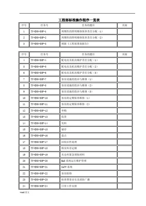
工程部标准操作程序一览表序号任务号任务的题目页面1 TY-ENG-SOP-1 周期性的照明维修保养责任分配(1)2 TY-ENG-SOP-2 周期性的照明维修保养责任分配(2)3 TY-ENG-SOP-3 填报《工程部事故报告》序号任务号任务的题目页面4 TY-ENG-SOP-4 配电房及机房维护责任分配(1)5 TY-ENG-SOP-5 配电房及机房维护责任分配(2)6 TY-ENG-SOP-6 配电房及机房维护责任分配(3)7 TY-ENG-SOP-7 客房设施的投诉与维修(1)8 TY-ENG-SOP-8 客房设施的投诉与维修(2)9 TY-ENG-SOP-9 客房设施的投诉与维修(3)10 TY-ENG-SOP-10 客房的定期保养维修(1)11 TY-ENG-SOP-11 客房的定期保养维修(2)12 TY-ENG-SOP-12 申购13 TY-ENG-SOP-13 收货14 TY-ENG-SOP-14 发料15 TY-ENG-SOP-15 储存16 TY-ENG-SOP-16 盘点17 TY-ENG-SOP-17 回收旧件处理18 TY-ENG-SOP-18 核实库存定额19 TY-ENG-SOP-19 从仓库紧急领取材料20 TY-ENG-SOP-20 BAS系统运行维护管理21 TY-ENG-SOP-21 CATV系统22 TY-ENG-SOP-22 客房检修23 TY-ENG-SOP-23 检查背景音乐及消防广播24 TY-ENG-SOP-24 日常工作安排25 TY-ENG-SOP-25 低压出线开关跳闸后的处理方法26 TY-ENG-SOP-26 照明检修27 TY-ENG-SOP-27 变电站常规检修内容及安全组织措施28 TY-ENG-SOP-28 低压联络开关故障处理方法29 TY-ENG-SOP-29 定期维修保养30 TY-ENG-SOP-30 应急发电机实验程序31 TY-ENG-SOP-31 低压线路维修工作注意事项32 TY-ENG-SOP-32 客房走廊照明检修33 TY-ENG-SOP-33 客房空调检查(1)34 TY-ENG-SOP-34 客房空调检查(2)序号任务号任务的题目页面35 TY-ENG-SOP-35 制冷机开/停操作程序36 TY-ENG-SOP-36 水泵启动运行中应注意的问题37 TY-ENG-SOP-37 空调运转操作规程(1)38 TY-ENG-SOP-38 空调运转操作规程(2)39 TY-ENG-SOP-39 冷冻机房值班规程(1)40 TY-ENG-SOP-40 冷冻机房值班规程(2)41 TY-ENG-SOP-41 锅炉紧急处理42 TY-ENG-SOP-42 客房卫生洁具的检查43 TY-ENG-SOP-43 泳、浴池水质的检测44 TY-ENG-SOP-44 锅炉紧急处理45 TY-ENG-SOP-45 检查浴缸水堵和马桶冲水时间46 TY-ENG-SOP-46 锅炉水位表冲洗程序47 TY-ENG-SOP-47 锅炉排污程序48 TY-ENG-SOP-48 锅炉紧急情况处理程序49 TY-ENG-SOP-49 缺水事故处理程序50 TY-ENG-SOP-50 年度客房检查维修(1)51 TY-ENG-SOP-51 年度客房检查维修(2)52 TY-ENG-SOP-52 年度客房检查维修(3)53 TY-ENG-SOP-53 火灾时,如何使用消防梯54 TY-ENG-SOP-54 电扒板、煎锅不加热的排除55 TY-ENG-SOP-55 洗碗机不喷水的排除56 TY-ENG-SOP-56 中餐炉火不旺的排除57 TY-ENG-SOP-57 制冰机不出冰的排除58 TY-ENG-SOP-58 执行会议、宴会设备设立任务序号任务号任务的题目页面59 TY-ENG-SOP-59 传真机、电话机安装60 TY-ENG-SOP-60 执行会议设备接待任务61 TY-ENG-SOP-61 PABX保养62 TY-ENG-SOP-62 临时增加会议设备63 TY-ENG-SOP-63 临时取消会议设备标准操作程序周期性的照明维护保养责任分配部门:工程部实行者职称:值班工程师及运行班人员任务号:TY-ENG-SOP-1 任务的题目:周期性的照明维护保养责任分配(1) 需要使用的用具:效益/质量标准:做什么怎么做 为什么1 客人区域照明维护保养一区二区三区四区将客人所到的区域照明以分工方式分配给各运行班负责客房、茶艺馆、西餐厅、以及卫生间洗衣房、员工宿舍以及卫生间大堂、餐厅、客房、商务中心、会议室、压力水泵房、厨房、大堂吧、点心厨房、会议中心环境路灯、避雷装置、雨水、污水排放、责任到人,提高保养质量,平衡工作量,以衡量各组工作表现的部分依据起草者:批准者:职称:签字/日期:职称:签字/日期:标准操作程序部门:工程部实行者职称:值班工程师及运行班人员任务号:TY-ENG-SOP-2 任务的题目:周期性的照明维护保养责任分配(2) 需要使用的用具:效益/质量标准:做什么怎么做 为什么照明维护保养的规范每月必须彻底检查及维修所负责区域之照明设备,以达到100%的正常,这也包括灯具及灯罩的端正牢固、吸顶灯灯罩与天花齐平悬挂端正无缺件、出口灯正常及灯具端正、灯槽内日光灯具不露出来等等。


WLJS/SC-2012质量、环境和职业健康安全整合型管理手册依据GB/T19001-2008(idt ISO9001:2008)GB/T50430-2007GB/T24001-2004(idt ISO14001:2004)GB/T28001-2011(idt OHSMS18001:2007)标准编制现行版本: A发放编号:持有者:2011-11-01发布2011-11-05实施•江西威乐建设集团有限公司发布•目录0 封面0.1 目录0.2 手册颁布令0.3 管理方针0.4 管理者代表任命书0.5 公司简介1 范围2 规范性引用文件3 质量管理基本要求3.1总则/总要求3.2 质量方针和目标3.2.2 目标/指标和管理方案3.3 质量管理体系的策划和建立3.4 质量管理体系的实施和改进3.5 文件和记录管理制度3.6 环境因素识别与评价控制程序3.7 危险源辨识与风险评价控制程序3.8 法律法规和其他要求的获取控制程序4 组织机构和职责4.1 总则4.2组织机构4.3 资源、作用、职责和权限5 人力资源管理5.1 总则5.2人力资源配置5.3能力、培训和意识6 施工机具管理6.1 总则6.2 施工机具配备6.3 施工机具使用7 投标及合同管理7.1 总则7.2 投标及签约7.3 合同管理8 建筑材料、构配件和设备管理8.1总则8.2 建筑材料、构配件和设备的采购8.3 建筑材料、构配件和设备的验收8.4 建筑材料、构配件和设备的现场管理8.5发包方提供的建筑材料、构配件和设备8.6 危险化学品的管理(采购、领用、仓储)9 分包管理9.1总则9.2 分包方的选择和分包合同9.3 分包项目实施过程的控制10 工程项目施工质量管理10.1 总则10.2 策划10.3 施工设计10.4 施工准备10.5 施工过程质量控制10.6 服务10.7 环境管理运行控制程序10.8 职业健康安全的运行控制程序10.9 应急准备和响应控制程序11 施工过程质量检查、验收与不合格工程的控制11.1 总则11.2 施工质量检查11.3 施工质量验收11.4 施工质量问题的处理11.5 检测设备管理12 质量管理自查与评价12.1总则12.2 质量活动的监督检查与评价12.3 环境管理运行控制的监视和测量(含不合格)12.4 职业健康安全管理运行控制的监视和测量(含不合格)12.5 内部审核控制程序12.6 合规性评价12.6.1 环境12.6.2 职业健康安全13 质量信息和质量管理改进13.1 总则13.2 质量信息的收集、传递、分析与利用13.3 管理评审13.4 质量管理改进与创新0.2手册颁布令为提供满足顾客(发包方)、用户和适应法律法规要求的房屋建筑工程、市政公用工程、公路工程、矿山工程、水利水电工程、园林绿化、建筑装修装饰工程、土石方工程、建筑防水工程的施工等工程产品,增强顾客(发包方)和相关方的满意,本公司结合行业特点和公司实际,制定了质量、环境和职业健康安全三标一体化的整合型《管理手册》,以适应企业发展和市场需求。

Oracle Primavera P6培训手册练习完成情况考核表学员姓名:___________________ 单位名称:___________________第一部分设置规划篇练习一设置用户参数完成□基本完成□未完成□练习二建立企业编码体系完成□基本完成□未完成□练习三管理用户及权限完成□基本完成□未完成□辅导教师签字:_______________第二部分进度计划编制篇练习四编制计划1.建立新项目完成□基本完成□未完成□2.建立项目计划的WBS结构完成□基本完成□未完成□3.编制作业计划完成□基本完成□未完成□4.限制条件完成□基本完成□未完成□5.创建工作产品及文档完成□基本完成□未完成□6.作业视图完成□基本完成□未完成□辅导教师签字:_______________第三部分资源费用篇练习五资源管理完成□基本完成□未完成□练习六自上而下的费用管理完成□基本完成□未完成□练习七自下而上的费用管理完成□基本完成□未完成□练习八视图报表的制作完成□基本完成□未完成□辅导教师签字:_______________第四部分实施、控制篇练习九项目进展情况跟踪完成□基本完成□未完成□练习十监控进度计算之前的临界值完成□基本完成□未完成□练习十一提出问题与解决问题完成□基本完成□未完成□练习十二对项目重新进行进度计算完成□基本完成□未完成□练习十三项目进展情况分析完成□基本完成□未完成□练习十四项目信息的组织和发布完成□基本完成□未完成□练习十五不同权限用户的责任对比完成□基本完成□未完成□辅导教师签字:_______________第一部分设置规划篇练习一、设置用户参数1、用户登录运行“Project Manager”程序,输入用户名:“admin”,输入口令:“admin”,点击“确定”按钮登录PM组件。
选择菜单“显示(V)”->“工具条(T)”,将“工具条”菜单中所有选项打上钩。
2.设置当前用户参数选择菜单“编辑(E)”->“用户设置(Z)…”,并按照下图所示设置当前用户的各个参数。
说明书ss目录前言1 安装运行维护中特别的安全说明2 本产品符合的标准及认证一、产品名称、规格和主要技术参数二、产品特点、主要用途及适用范围2.1产品特点2.2 主要用途2.3 适用范围三、本产品组成及工作原理四、控制系统说明五、安装与调试方法六、使用与操作方法七、本产品的维护和保养八、安全保护装臵及事故处理方法九、外形尺寸及重量十、本产品工作条件和环境要求十一、环境健康安全注意事项十二、公司名称地址及联系电话前言1 安装运行维护中特别的安全说明1)只有经过培训的合格的人员才能操作提升机,操作前注意旋转部分有无护罩,防止挂伤。
2)只有合格的电气技术人员才能维修、安装、配线本提升机电控设备,不正确的操作会导致人身伤害或设备损坏。
3)电控设备必须有专业人员严格接地。
4)高电压设备的停送电按批准的程序进行,防止触电危险,裸露的带电部分应加装足够安全距离的护栏。
5)电源开关断开后,仍然有高电压存在,请对地放电后再进行检修工作。
2 本产品符合的标准及认证本产品按“HMA-JT1.9901电控设备通用技术条件”设计、生产、检验。
本产品按“JB4263-2000交流传动矿井提升机通用技术条件”标准执行。
《煤矿安全规程》(2005年版)。
现行国家电工委员会及其它有关标准。
进口电气设备遵守国际电工委员会IEC标准。
工程有限责任公司使用说明书共20页第 3 页一、产品名称、规格和主要技术参数1 产品名称、规格提升机交流变频电控设备图号:DH2502 主要技术参数1.提升水平:单水平提升和多水平提升2.操作方式:半自动、手动、检修等方式3.拖动方式:全数字变频拖动4.操纵台:三体式操纵台带数字深度指示5.控制方式:采用主从双PLC控制6.监控方式:上位监控系统(采用工控机)二、产品特点、主要用途及适用范围1 产品特点成套电控主要由低压配电系统、操作系统、安全保护系统、监控系统、全数字变频驱动系统组成。
操作系统选用两台西门子原装PLC (S7-300)作为操作的主控单元;安全保护采用软、硬件两路安全回路实现双重保护;监控系统由工业控制计算机配臵监控软件组成;全数字变频调速系统由西门子原装6SE70变频调速装臵组成。

工程技术操作手册1、内容及适用范围主要内容包括:1.1 图纸自审;1.2 图纸会审;1.3 施工组织设计(方案)的编制与管理;1.4 施工作业指导书的编制与管理;1.5 技术交底;1.6 技术核定;1.7 单位工程施工记录;1.8 技术复核;1.9 隐蔽工程验收;1.10 科技开发和推广应用管理;1.11 施工技术总结;1.12 技术标准管理;1.13 工程技术档案;1.14 技术洽商管理制度;1.15 材料试验管理规定;1.16 施工试验管理;1.17 工程预检管理;1.18 基础、结构验收记录管理。
本操作手册适用各项目工程的技术管理。
2、图纸自审2.1 图纸自审根据项目建筑面积分两种情形开展:5万平方米以下项目,由项目经理组织项目自审;5万平方米以上由分公司技术质检科长/总工负责组织开展自审。
2.2 接到图纸后,项目经理或技术质检科长/总工及时安排建筑集团、安装、装潢技术员、相关专业工长、预算员、质量员、钢筋翻样等进行自审,并提出各专业自审记录。
2.3 及时召集有关人员,组织内部会审,针对各专业自审发现的问题及建议进行讨论,弄清设计意图和工程的特点及要求。
2.4 图纸自审的主要内容:2.4.1 各专业施工图的张数、编号、与图纸目录是否相符。
2.4.2 施工图纸、施工图说明、设计总说明是否齐全,规定是否明确,三者有无矛盾。
2.4.3 平面图所标注坐标、绝对标高与总图是否相符。
2.4.4 图面上的尺寸、标高、预留孔及预埋件的位置以及构件平、立面配筋与剖面有无错误。
2.4.5 建筑施工图与结构施工图,结构施工图与设备基础、水、电、暖、卫、通等专业施工图的轴线、位置(坐标)、标高及交叉点是否矛盾。
平面图、大样图之间有无矛盾。
2.4.6 图纸上构配件的编号、规格型号及数量与构配件一览表是否相符。
2.5 图纸经自审后,应将发现的问题以及有关建议,做好记录,待图纸会审时提交讨论解决。
3、图纸会审3.1 图纸会审目的了解设计意图,明确质量要求,将图纸上存在的问题和错误,专业之间的矛盾等,尽最大可能解决在工程开工之前。
建筑施工企业OHS手册一、公布令及治理者代表任命书二、公司简介三、职业安全健康方针、目标职业安全健康治理手册内容1目的和使用范畴2引用标准、定义、术语及缩写代号3手册的治理4职业安全健康治理体系要素4.1 总要求4.2职业安健康全方针4.3.1危险源辨识、危险评判和危险操纵打算4.3.2法律及法规要求4.3.3目标4.3.4职业安全健康治理方案4.4.1机构和职责4.4.2培训、意识和能力4.4.3协商与交流4.4.4职业安全健康治理体系文件4.4.5文件和资料操纵4.4.6运行操纵4.4.7应急预案与响应4.5.1绩效测量和监测4. 5.2事故、事件、不符合、纠正与预防措施4.5.3记录和记录治理4.5.4审核4.6治理评审四、附录职业健康安全手册公布令及治理者代表任命书XXXX建设《OHS治理体系手册》是依据GB/T28001-2001 《职业健康安全治理体系—规范》编写,旨在使公司具备稳固的健康安全保证能力,操纵职业健康安全风险并改进其绩效,属于公司纲领性文件,同时又是开展业务培训、内部审核的依据。
本手册(B版)为第一版手册运行的基础上修订而成,符合GB/T28001-2001以及公司的实际,现批准颁发,并于2004年9月10日正式实施,公司全体职员应认真学习《OHS治理体系手册》,并贯彻执行。
为建立公司的职业安全健康治理体系,按照确立的职业安全健康方针、目标和指标,搞好体系的运行及与外部的联络,经研究任命XX同志为公司职业安全健康治理者代表,并自签发之日起生效。
董事长:日期:2004年9月8日公司概况XXXX建设成立时刻于1993年8月,为房屋建筑工程施工总承包二级资质企业,注册资金2099万,各类工程技术人员218人,多年来取得了良好的经济效益和社会效益,始终保持合同履约率100%,质量合格率100%,未发生任何大事故。
公司全体职员以“质量第一,用户至上,优质服务,信守合同”为宗旨,珍爱来之不易的荣誉,将以更加优异的成绩回报社会。

沃尔沃物流信息服务平台软件需求规格说明书变更记录目录1概述 ............................................................................. ....................................................................... 4 1.1 1.21.3 22.1编写目的 ............................................................................. ...................................................... 4 系统目标 ............................................................................. ...................................................... 4 术语定义 ............................................................................. ...................................................... 7 物流信息服务平台 ............................................................................. .. (9)首页 ............................................................................. ...................................................... 9 物流需求发布 ............................................................................. .................................... 10 物流解决方案 ............................................................................. .................................... 10 物流企业园区 ............................................................................. .................................... 11 物流联盟论坛 ............................................................................. .................................... 12 物流效率测算 ............................................................................. .................................... 12 新闻维护 ............................................................................. ............................................ 14 物流项目发布 ............................................................................. .................................... 14 论坛维护 ............................................................................. ............................................ 15 物流运营数据分析系统维护 ............................................................................. ............ 16 数据字典 ............................................................................. ............................................ 17 网站用户管理 ............................................................................. .................................... 17 平台系统管理 ............................................................................. (21)需求说明 ............................................................................. ............................................................... 9 2.1.1 2.1.22.1.3 2.1.4 2.1.5 2.1.6 2.2 2.2.1 2.2.2 2.2.3 2.2.4 2.2.5 2.2.6 2.2.7物流信息服务平台管理系统 ............................................................................. .. (14)3 4 5 6性能要求 ............................................................................. ............................................................. 23 可维护性, 可扩展性 ............................................................................. .......................................... 24 安全性 ............................................................................. ................................................................. 25 设计约束 ............................................................................. ............................................................. 26 6.1.1 6.1.2 语言约束 ............................................................................. ............................................ 26 系统模型约束 ............................................................................. (26)7 8 9界面要求 ............................................................................. ............................................................. 27 验收标准 ............................................................................. ............................................................. 29 附件 ............................................................................. (30)1 概述1.1 编写目的本文档是北京软通动力科技有限公司(以下简称软通)在沃尔沃(中国)投资有限公司(以下简称沃尔沃)的物流信息服务平台合同基础上编制的。
前言 (3)第一部分安防系统产品介绍 (4)1.1家庭智能防盗报警主机(型号:JZ-A-101 ) (4)1.2 8防区报警信号控制模块(型号:JZ-A-102 ) (5)1.3 系统电源(型号:JZ-A-111 ) (5)1.4 楼层保护器(型号:JZ-A-112 ) (6)1.5 家防信号转发器(型号:JZ-A-201 ) (6)1.6 路由器(型号:JZ-A-203 ) (7)1.7 信号中继器(型号:JZ-A-113 ) (7)1.8 周界单防区模块(型号:JZ-A-105 ) (7)1.9 周界信号转发器(型号:JZ-A-202 ) (8)1.10 报警信号驱动模块(型号:JZ-A-107 ) (9)1.11 信号输岀放大模块(型号:JZ-A-108 ) (9)1.12 周界联动模块(型号:JZ-A-106 ) (9)1.13 LON PCI 网卡(型号:JZ-A-301 )..................................................................... 1 01.14 软件包(型号:JZ-A-302 ,版本号JZAS ECURITY V2.0 ) .......... 1 0第二部分安防产品接口说明.......................................................... 1 22.1家庭智能防盗报警主机(型号:JZ-A-101 ) .................................................. 1 22.2 8防区报警信号控制模块(型号:JZ-A-102 ) .......................................... 1 22.3楼层保护器(型号:JZ-A-112 )................................................... 1 32.4 信号转发器(型号:JZ-A-201/JZ-A-202 ) ..................................................... 1 42.5 系统电源(型号:JZ-A-111 ) .................................................................................. 1 42.6 路由器(型号:JZ-A-203 ) 1 52.7 信号中继器(型号:JZ-A-113 ) 1 52.8 周界单防区模块(型号:JZ-A-105 ) 1 62.9 报警信号驱动模块(型号:JZ-A-107 ) 1 62.10 信号输岀放大模块(型号:JZ-A-108 ) ...................................... 1 6第三部分系统安装调试说明.......................................................... 1 73.1 布线与安装说明 ........................................................... 1 73.1.1 布线说明............................................................. 1 73.1.2 安装说明............................................................. 1 73.2 调试说明.................................................................. 1 83.2.1 检查电源............................................................. 1 83.2.2 单元调试............................................................ 1 83.2.3 系统调试............................................................. 1 93.2.4 软件调试............................................................. 1 93.3 常见故障排除 ............................................................. 2 03.4 申请厂方调试 ............................................................. 2 13.5 终端地址编码样表及附图.................................................... 2 2世科牌智能防盗报警系统概述为适应新世纪人们对居住环境的新要求,根据相关标准要求,本公司研制推出世科牌JZ-A型智能防盗报警系统。
山东省银河伟业物业管理有限责任公司目录第一部分公司管理制度 (1)一、公司简介 (1)二、公司组织机构图 (2)三、员工守则 (3)四、员工礼仪规范 (3)五、员工工装管理规定 (6)六、员工培训管理规定 (8)七、员工聘用、辞职(辞退)管理规定 (10)八、员工考勤管理规定 (12)九、物品采购制度 (15)十、物品出入库管理制度 (15)十一、公司档案管理制度 (16)十二、公司印章管理规定 (17)十三、公司会议管理规定 (17)十四、关于工作期间严禁酗酒的规定 (18)第二部分工程服务管理制度 (19)一、工程服务组织架构 (19)(一)工程服务部组织机构图 (19)(二)工程服务部主要工作职责 (20)二、工程服务指引(范本) (20)三、工程服务注意事项 (23)山东省银河伟业物业管理有限责任公司四、工程主管主要例行工作 (24)五、职位说明书 (25)(一)工程主管职位说明书 (25)(二)技工(管道工)职位说明书 (26)(三)技工(电梯)职位说明书 (27)(四)技工(强电工)职位说明书 (28)(五)技工(弱电工)职位说明书 (29)(六)技工(配电室值班员)职位说明书 (30)六、工程服务规范 (31)(一)工程服务规范(共用部分) (31)(二)工程服务规范(上门维修服务) (36)七、工程计划管理要求 (37)(一)总体要求 (37)(二)计划与方案 (38)八、设施设备管理要求 (41)(一)设施日常巡检管理要求 (41)(二)设备运行巡检管理要求 (46)(三)共用部位/设施定期维护管理要求 (98)(四)设备定期维护管理要求 (101)(五)设施设备定期修理管理要求 (152)九、工程服务质量检查表 (158)十、作业指导 (186)山东省银河伟业物业管理有限责任公司第一部分公司管理制度一、公司简介山东省银河伟业物业管理有限责任公司成立于2004年4月,隶属济南市槐荫区住房保障和房产管理局,注册资金300万,国家二级物业管理资质,ISO9000国际质量体系认证企业。
( 员工手册)姓名:____________________单位:____________________日期:____________________编号:YB-BH-020425建筑企业质量手册范本Model quality manual for construction enterprises建筑企业质量手册范本建筑企业质量手册如下1、开工前应提交“工程开工报审表”经监理单位审查同意后开工。
工程开工应具备下列条件:(1)工程设计文件已通过施工图审查机构的审查;(2)高程和平面控制网已经规划部门确定;(3)已办妥工程质量监督、安全监督手续和施工许可证;(4)进场道路及水、电、通讯等已满足开工要求;(5)建设资金已落实;(6)已签订工程施工承包合同,已完成施工图会审、设计技术交底、施工组织设计编制、审批,现场管理人员已到位,施工人员、机具、材料已落实并进场,现场质量安全管理制度已制定,各专业管理人员的数量和资格符合规定;(7)主要材料(商品混凝土)供应单位、工程检测单位、沉降观测单位已落实;(8)建筑物定位放线已经城市规划部门认可。
2、及时报审《单位工程施工组织设计》和“专项施工方案”。
施工组织设计及施工方案必须手续齐全,有编制人签字、审核人和企业技术负责人审批意见明确,签字盖章齐全。
对应组织专家论证审查的危险性较大工程应提前组织专家论证审查。
施工组织设计和专项施工方案应提前7天填写“施工组织设计/方案报审表”送监理审批,经监理批准后实施。
3、及时办理建筑材料、构配件和设备进场报验手续。
建筑材料、构配件和设备进场应技术填写“建筑材料(构配件)、设备进场使用报验单,”报请现场监理对进场的建筑材料、构配件和设备进行验收,未经监理验收或验收不合格不得使用。
按照规定应当实行见证取样检测的建筑材料和构配件,应当按照“见证取样制度”的规定进行建筑取样检测。
4、及时办理工序质量报验手续。
在施工单位自检合格的基础上,填写“工序质量报验单”,通知现场监理进行现场检查验收,经监理验收合格后可进行下道工序的施工。