003-力控计算引擎Fcyber使用文档
- 格式:pdf
- 大小:4.19 MB
- 文档页数:26
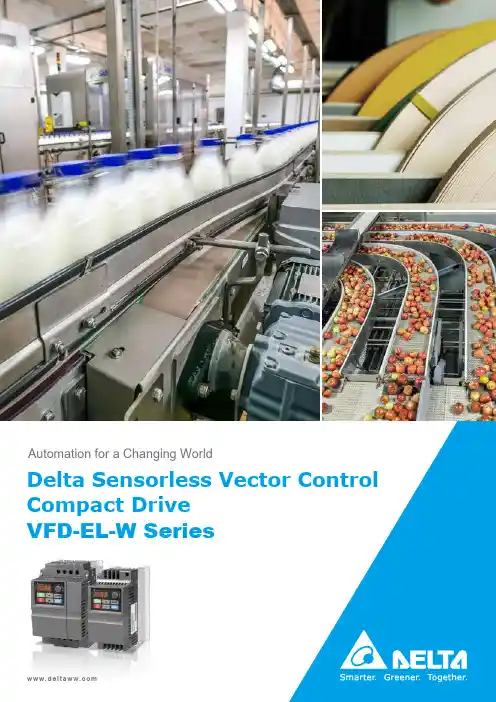
Delta Sensorless Vector Control Compact Drive VFD-EL-W SeriesAutomation for a Changing WorldSensorless Vector Control Compact Drive VFD-EL-W SeriesSimple Speed ControlHorizontal MovementFixed Load ApplicationsFrame A1Frame BFrame A2Natural cooling (Frame A1): no maintenance requiredFan cooling (Frame A2, Frame B): easy fan installation, reliable design, fast dust removal150 % / 60 secs overload capability150% 60sCE certificationEnergy-savingSingle / multi-pump control:constant pressure mode & alternative operationProtection: overload, over voltage / over current stall preventionBuilt-in PID feedback controlP I DSafety and ReliabilityEasy MaintenanceComplete FunctionsApplicationsEdge Banding Machine• Communication isolation reduces the interference of HMI• One drive for two motors in parallel• Optimized accel. / decel. improve system efficiency• Small size, lightweight, easy maintenance and installationLogistics Conveyor• Built-in RS-485 COM port for high-speed communication• Fast and stable tension control• Small and compact design to save installation spaceMaterial Handling Machine• Multiple speed adjustment modes for different applications• AVR function to ensure the stability and reliability• Speed tracking function for continuing operation afterpower resumes from an instantaneous power failureConstant Pressure Pump• Build-in PID pressure control; no need for external PID device to save system cost• Built-in automatic inspection and restoration functionsin case of water outage; no external PLC needed• System leakage control function• Multi-pump control: alternates pump operation in cycle(One drive supports max. 4 pumps)Wiring230V / 460V ModelsControl TerminalsMI1MI2MI3MI4SG+SG-PIN3: GND PIN4: SG-PIN5: SG+U(T1)V(T2)W(T3)+10V AVI/ACI ACM 123Fuse/NFB (No Fuse Breaker)FactorySetting Run/StopMulti-step1Multi-step2Digital Signal CommonFactory setting is malfunction indication IM 3~Motor Multi-function Contact Output +24V AVI ACISwitchNPN PNPMain Circuit (power) Terminals Control Circuit Terminals Shielded Leads & CableEERA RB RC R(L1)S(L2)T(L3)(R)L N (S)(T)ETerminal SG+, SG- are joined to PIN5, PIN4 of RJ45 ConnectorDCM Multi-step38 1Switch(Default)(Default)RARBRCMI1MI2MI3DCMSG+SG -ACM +10V AVIRS-485Control Terminal LocationNPN AVI ACIPNP+24V MI4Frames and AppearancesInput Terminals (R / L1, S / L2, T / L3)Digital KeypadControl Board Cover Output Terminals (U / T1, V / T2, W / T3) ■Frame A1 / A 2Digital Keypad Choose NPN / PNP Control Terminals RS-485 Terminal(RJ45)■Frame BInput Terminals (R / L1, S / L2, T / L3)Digital Keypad Control Board CoverOutput Terminals (U / T1, V / T2, W / T3)CaseGrounding TerminalsFrequency Control Potentiometer Frequency Control Potentiometer Choose ACI / A VIA B C D E Digital KeypadChoose NPN / PNP Control Terminals RS-485 Terminal(RJ45)Choose AVI / A CIA B C D E CABDECABDEGrounding Terminals Cooling Fan* Frame A1 does not include a cooling fanModel ExplanationVFD 007 EL 21 W -1Minimal & Economic Input Voltage21: 230 V 1 PH 43: 460 V 3 PHVFD-EL-W SeriesApplicable Motor Capacity002: 0.25 HP (0.2 kW)004: 0.5 HP (0.4 kW)007: 1 HP (0.75 kW) 015: 2 HP (1.5 kW)022: 3 HP (2.2 kW)040: 5 .5 HP (4.0 kW)Variable Frequency DriveMethods of Packing-1: Individual Package N/A: 12 pcs / CartonVoltage 230 V460 V FrameA1BA1A2BModelVFD-__EL21W(-1) VFD-__EL43W(-1)002004007015022004007015022040Max. Applicable Motor Output (kW)0.20.40.75 1.5 2.20.40.75 1.5 2.2 4.0Max. Applicable Motor Output (HP)0.250.5 1.0 2.0 3.00.5 1.0 2.0 3.0 5.5Output RatingRated Output Capacity (kVA)0.6 1.0 1.6 2.9 4.2 1.2 2.0 3.3 4.47.4Rated Output Current (A) 1.62.54.27.511.01.52.54.25.59.0Maximum Output Voltage (V)3-Phase Proportional to Input VoltageOutput Frequency (Hz)0.1 ~ 400Carrier Frequency (kHz) 2 ~ 12 (Default 8 kHz)Input Rating Rated Input Current (A)4.96.59.315.724.01.83.24.37.110.0Rated Voltage / Frequency Single Phase, AC 200 V ~ 240 V ,50 / 60 HzThree Phase, AC 380 V ~ 480 V ,50 / 60 HzVoltage Tolerance±10 % (180 V ~ 264 V)±10 % (342 V ~ 528 V)Frequency Tolerance±5 % (47 Hz ~ 63 Hz)Weight (kg) 1.0 1.4 1.01.4Cooling Method Natural CoolingFan CoolingNatural CoolingFan CoolingBrake Unit N/A DC Choke N/A EMI FilterN/AProduct SpecificationsSpecificationsC o n t r o l C h a r a c t e r i s t i c sControl SystemSPWM (Sinusoidal Pulse Width Modulation) control (V / F Control, Vector Control)Frequency Setting Resolution 0.01 Hz Output Frequency Resolution0.01 HzTorque Characteristics Including the auto-torque, auto-slip compensation; starting torque can be 150 % at 5 Hz Overload Endurance 150 % of rated current for 1 minuteSkip Frequency Three zones, setting range 0.1 ~ 400 HzAccel. / Decel. Time 0.1 to 600 secs (2 independent setting for accel. / decel. time)Stall Prevention LevelSetting 20 to 250 % of rated currentDC Brake Operating frequency 0.1 ~ 400 Hz, Output 0 ~ 100 % rated current Start time 0 ~ 60 secs, stop time 0~60 secs V / F PatternAdjustable V / F pattern O p e r a t i n g C h a r a c t e r i s t i c sFrequency SettingKeypadSetting by▲▼External Signal Potentiometer : 5k Ω / 0.5 W, 0 to +10 VDC, 4 to 20 mAMulti-function input MI2 ~ MI4 (8 steps : Including the main speed, jog, up / down); RS-485 serial interface Operating Setting SignalKeypad Setting by RUN and STOPExternal SignalRUN / STOP by MI1 (default) or 2-wire / 3-wire control (MI1, MI2, MI3), jog operation, RS-485 serial interface (Modbus)Multi-function Input Signal8-speed switch (including the main speed): ban commands for acceleration / deceleration, 2-speed switch for accel. / decel., counter, jogging (inching), external base block, driver reset, NPN / PNP inputs, AVI / A CI analog inputs Switch to a speed as the default.Multi-function Output Signal(only Relays) AC drive operating, frequency attained, zero speed, counter, over-torque inspection, external base block, operating modes, anomaly alarm, overheating alarm, emergency stopProtection FunctionsOver voltage, over current, under voltage, anomalies, overload, overheating, electronic thermal relays, PTC overheating protectionOperation FunctionsBuilt-in voltage regulators, accel. / decel. S-curve, over-voltage / over-current stall prevention, 5 anomalous logs, reverse ban, restart for instantaneous power outage, DC brake, automatic toque / slip compensation and motor parameter adjustment, carrier frequency setting, output frequency limits, parameter reset, PID control, external counter, Modbus protocol, reset and restart for anomalies, energy-saving, fan control (for models with fans), 1st / 2nd frequency sources and combination, NPN / PNP inputsDisplay Keypad (optional) 6 function keys, 4-digit 7-segment LED, 4 status LEDs, adjustable frequency, self-defined units, parameter settings and lock function, anomaly alarms, Run / Stop / Reset buttons E n v i r o n m e n t a l C o n d i t i o n sEnclosure Rating IP20Pollution Degree 2Installation Location Altitude 1,000 m or lower, keeping from corrosive gases, liquids and dust Operating Temperature -10°C to 50°C (VFD007EL21W(-1) requires fan accessories)Storage / TransportationTemperature -20°C to 60°CAmbient HumidityBelow 90 % RH (non-condensing)Vibration 1.0 mm, peak to peak 2–13.2 Hz; 0.7–1.0 G, 13.2–55 Hz; 1.0 G, 55–512 Hz; compliant with IEC 60068-2-6 Certification, RoHS, GB 12668.3SpecificationsGeneral Specifications■Frame A1■Frame A2ModelVFD002EL21W(-1)VFD004EL21W(-1)VFD004EL43W(-1)VFD007EL21W(-1)VFD007EL43W(-1)Frame W W1H H1D D1S A1mm 92.082.0162.0152128.7 2.00 5.4inch3.62 3.23 6.38 5.98 5.070.080.21DimensionsModelVFD015EL43W(-1)Frame W W1H H1H2D D1S A2mm 92.082.0180.5162.0152128.7 2.00 5.4inch3.62 3.237.11 6.38 5.98 5.070.080.21SA(Mounting Hole )W1W DSee AH 1HD1W1W H 1HH 2SADSee AD1(Mounting Hole )Frame W W1H H1D D1S1S2Bmm 100.089.0174.0162.9136.0 4.0 5.9 5.4inch3.94 3.50 6.85 6.42 5.350.160.230.21ModelVFD015EL21W(-1)VFD022EL21W(-1)VFD022EL43W(-1)VFD040EL43W(-1)Ordering InformationFrameCooling MethodOperating TemperaturePower RangeModels Frame A1Natural Cooling-10°C ~ 50°C 230 V: 0.2 ~ 0.75 kW 460 V: 0.4 ~ 0.75 kWVFD002EL21W(-1)VFD004EL21W(-1)VFD004EL43W(-1)VFD007EL21W(-1)* VFD007EL43W(-1)Frame A2Fan Cooling460 V: 1.5 kW VFD015EL43W(-1)Frame B230 V: 1.5 ~ 2.2 kW 460 V: 2.2 ~ 4.0 kWVFD015EL21W(-1)VFD022EL21W(-1)VFD022EL43W(-1)VFD040EL43W(-1)■Frame BVFDxxxELxxW-1 and VFDxxxELxxW share the same electrical specifications.*VFD007EL21W(-1): to reach 50℃operating temperature, a fan kit MKEL-AFKM1 is required (without derating). *VFD007EL21W(-1): to reach 40℃operating temperature, no need for a fan kit (without derating).W1H 1W HDS1D1AS2BSee ASee B(Mounting Hole )(Mounting Hole )10AccessoriesKeypadCableFan kitReactorVFD-PU06VFD-PU08RJ45 CableVFD-PU08VRF220X00AMKEL-AFKM1• 5 digits• Parameter duplication and recording • RJ11 connector • RS-485 communication• 4 digits• RJ45 connector• RS-485 communication• 4 digiits• RJ45 connector• RS-485 communicationNo.ModelLengthmm inch 1UC-CMC003-01A 30011.82UC-CMC005-01A 50019.63UC-CMC010-01A 100039.04UC-CMC015-01A 150059.05UC-CMC020-01A 200078.76UC-CMC030-01A 3000118.17UC-CMC050-01A5000196.8* RJ45 cable is not included for VFD-PU08 & VFD-PU08V.DELTA_IA-MDS_VFD-EL-W_C_EN_20200716Industrial Automation HeadquartersDelta Electronics, Inc.Taoyuan Technology CenterNo.18, Xinglong Rd., Taoyuan District, Taoyuan City 33068, TaiwanTEL: 886-3-362-6301 / FAX: 886-3-371-6301AsiaDelta Electronics (Shanghai) Co., Ltd.No.182 Minyu Rd., Pudong Shanghai, P .R.C.Post code : 201209TEL: 86-21-6872-3988 / FAX: 86-21-6872-3996Customer Service: 400-820-9595Delta Electronics (Japan), Inc.Tokyo OfficeIndustrial Automation Sales Department 2-1-14 Shibadaimon, Minato-ku Tokyo, Japan 105-0012TEL: 81-3-5733-1155 / FAX: 81-3-5733-1255Delta Electronics (Korea), Inc.Seoul Office1511, 219, Gasan Digital 1-Ro., Geumcheon-gu, Seoul, 08501 South KoreaTEL: 82-2-515-5305 / FAX: 82-2-515-5302Delta Energy Systems (Singapore) Pte Ltd.4 Kaki Bukit Avenue 1, #05-04, Singapore 417939TEL: 65-6747-5155 / FAX: 65-6744-9228Delta Electronics (India) Pvt. Ltd.Plot No.43, Sector 35, HSIIDC Gurgaon, PIN 122001, Haryana, IndiaTEL: 91-124-4874900 / FAX : 91-124-4874945Delta Electronics (Thailand) PCL.909 Soi 9, Moo 4, Bangpoo Industrial Estate (E.P .Z), Pattana 1 Rd., T.Phraksa, A.Muang, Samutprakarn 10280, ThailandTEL: 66-2709-2800 / FAX : 662-709-2827Delta Electronics (Australia) Pty Ltd.Unit 20-21/45 Normanby Rd., Notting Hill Vic 3168, Australia TEL: 61-3-9543-3720AmericasDelta Electronics (Americas) Ltd.Raleigh OfficeP .O. Box 12173, 5101 Davis Drive,Research Triangle Park, NC 27709, U.S.A.TEL: 1-919-767-3813 / FAX: 1-919-767-3969Delta Greentech (Brasil) S/ASão Paulo OfficeRua Itapeva, 26 – 3˚ Andar - Bela Vista CEP: 01332-000 – São Paulo – SP - Brasil TEL: 55-11-3530-8643 / 55-11-3530-8640Delta Electronics International Mexico S.A. de C.V.Mexico OfficeGustavo Baz No. 309 Edificio E PB 103Colonia La Loma, CP 54060Tlalnepantla, Estado de México TEL: 52-55-3603-9200*We reserve the right to change the information in this catalogue without prior notice.EMEAHeadquarters: Delta Electronics (Netherlands) B.V.Sales:*************************Marketing:*****************************TechnicalSupport:******************************CustomerSupport:****************************Service:***************************TEL: +31(0)40 800 3900BENELUX: Delta Electronics (Netherlands) B.V.De Witbogt 20, 5652 AG Eindhoven, The Netherlands Mail:****************************TEL: +31(0)40 800 3900DACH: Delta Electronics (Netherlands) B.V.Coesterweg 45, D-59494 Soest, Germany Mail:*************************TEL: +49(0)2921 987 0France: Delta Electronics (France) S.A.ZI du bois Challand 2, 15 rue des Pyrénées, Lisses, 91090 Evry Cedex, France Mail:***********************TEL: +33(0)1 69 77 82 60Iberia: Delta Electronics Solutions (Spain) S.L.UCtra. De Villaverde a Vallecas, 265 1º Dcha Ed. Hormigueras – P .I. de Vallecas 28031 Madrid TEL: +34(0)91 223 74 20Carrer Llacuna 166, 08018 Barcelona, Spain Mail:***************************Italy: Delta Electronics (Italy) S.r.l.Via Meda 2–22060 Novedrate(CO) Piazza Grazioli 18 00186 Roma Italy Mail:**************************TEL: +39 039 8900365Russia: Delta Energy System LLCVereyskaya Plaza II, office 112 Vereyskaya str. 17 121357 Moscow RussiaMail:***********************TEL: +7 495 644 3240Turkey: Delta Greentech Elektronik San. Ltd. Sti. (Turkey)Şerifali Mah. Hendem Cad. Kule Sok. No:16-A 34775 Ümraniye – İstanbulMail:***************************TEL: + 90 216 499 9910GCC: Delta Energy Systems AG (Dubai BR)P .O. Box 185668, Gate 7, 3rd Floor, Hamarain Centre Dubai, United Arab EmiratesMail:************************TEL: +971(0)4 2690148Egypt + North Africa: Delta ElectronicsUnit 318, 3rd Floor, Trivium Business Complex, North 90 street, New Cairo, Cairo, EgyptMail:************************。
DescriptionAccessories contribute to a reliable transducer system. Installing proximity probes during outages usually requiresone or more mounting accessories to help simplify the task.3300XL Transducer AccessoriesDatasheetBently Nevada Machinery Condition Monitoring145668Rev.HThese accessories allow you to quickly and efficiently install proximity probes and route the associated cables out of the machine case. These parts also help shield the cables from electrical noise and adverse environmental conditions. Having the proper mounting hardware on-site during the probe installation saves time and money for those responsible for the project.Junction boxesJunction boxes are normally mounted on or near the exterior of a machine case and enclose electrical connections in weatherproof or explosion-proof environments. Sealtite™ flexible conduit Flexible conduit routes probe cables safely to the sensor housing and then back to the monitors. The conduit protects transducer wiring from damage that splashing liquids or accidental contact with other equipment can cause.Sealtite flexible conduit consists of a galvanized steel core with an extruded thermoplastic cover. Pipe fittings are made of steel with a zinc-plated, chromate finish and are compatible with fittings found on our watertight equipment enclosuresProbe mounting bracketsProbe mounting brackets attach internally mounted proximity probes to the machine case. S upplied mounting bolts attach the bracket to the bearing or other location inside the machine casing. The bracket holds the probe and allows for adjustment of the probe tip relative to the observed surface.For most installations, use the standard 137492 non-clamping aluminum probe bracket. When using the 137491 brackets for 3/8-inch diameter smooth case probes, tightening the bolts will compress the probe hole around the probe and lock the probe into its preset gapped position. If your application requires additional electrical isolation from the mounting location (as in some generator and electric motor bearing locations), use the 27474 phenolic probe bracket. These mounting brackets are compatible with our 3300 and 3300 XL proximity probe systems, including 5 mm, 8 mm and NSv™ probes.To ensure that the brackets screws remain fastened within the machine, secure the screws with safety wire. Each mounting bracket includes special screws with holes drilled for safety wire.Cable SealThe optional 10076 Cable Seal is mainly for use in cable routing applications. It restrains the coaxial cable from movement, prevents abrasion, and provides splash protection. One end of the cable seal has a 1/4-18 NPT thread that allows you to thread it into a 4190-36 Adapter.The cable seal has an aluminum body and an oil-resistant, slit grommet so that you can install it over armored or non-armored cable without removing the connectors. AdapterThe optional 4190 Adapter attaches a junction box to the machine case. It also allows mounting of the proximity probe in some instances.The adapter offers a variety of threads and configurations. A dapter threads and configurations that are not listed in this data sheet may be available. P lease contact your sales representative for more information. Explosion-proof fittingsExplosion-proof fittings provide seals for housings in Division 1 and in Zone 0 and 1 hazardous areas. The fittings include sealing compound, packing fiber, and the appropriate adapter. Fitting kits are available. Refer to Explosion-Proof Fittings on page 6 for details and part numbers.Low-pressure cable sealThe 43501 Low-Pressure Cable Seal provides egress for up to 4 75Ω and/or 95Ω 3300XL, 3300 and 7200 cables, or up to 2 25mm DE or 50mmDE transducer cables, through a single hole in a machine case or other barrier.The cable seal is constructed of 303 stainless steel and a molded silicon rubber grommet and prevents leakage of fluids along the outer jacket of the cable. The seal has threads on both ends and fits into a tapped hole on the machine case or barrier. External pipe threads enable the seal to mate to conduit or housings. You can use the low-pressure cable seal only with non-armored cables. Its design seals pressures up to 345 kPa (50 psi) when properly installed.High-Temperature Cable TiesThe 173873 high-temperature cable tie is an economical alternative to metal brackets in high-temperature applications. These cable ties are molded from VICTREX® PEEK™ polymer for multiple uses in extreme environments up to +180°C (+356°F).SpecificationsJunction BoxesCylindrical Junction Box P/N 03818016 ComponentsMain body and blankcoverDimensionsOverall Height76 mm (3.0 in)Body Diameter89 mm (3.5 in)Hub-to-Hub121 mm (4.75 in) Base to Hub Center16 mm (0.64 in) Fittings3/4-14 NPT5 placesMaterial AluminumOptional Extension for 03818016 P/N 03818022ComponentsMain body Dimensions (Extensiononly)Overall Height93mm (3.7 in)Body Diameter90mm (3.6 in)Hub-to-Hub (flats)91 mm (3.6 in)Total ExtendedHeight150 mm (5.90 in) Material Aluminum Rectangular Junction Box P/N 03818065 ComponentsMain body and cover Dimensions Overall Height27.9 mm (1.10 in) Width of Body38.1 mm (1.50 in) Length of Body95.3 mm (3.75 in) Fittings1/2-14 NPT2 places Material Aluminum Rectangular Junction Box P/N 03818066 ComponentsMain body and cover Dimensions Overall Height61.0 mm (2.40 in) Width of Body44.5 mm (1.75 in) Length of Body102 mm (4.00 in) Fittings3/4-14 NPT2 places Material Aluminum Sealtite Flexible Conduit Components Refer to Figure 4.Fitting Options1/2-14 NPT3/4-14 NPTLength As ordered BracketsClamp Mounting Bracket for 3/8-inch diameter smooth body probesDimensions Refer to Figure 5.Mounting Screw Thread Size Options 10-24 UNC-2A M5 x 0.8-6gMaterial AluminumNon-Clamping Mounting Bracket for threaded case probesDimensions Refer to Figure 6. Mounting Screw Thread Size10-24 UNC-2Aor M5 x 0.8-6g Material Aluminum Probe Lock NutThread Sizes 3/8-24 UNF-2B M10 x 1-6HFeatures Lock nut with holes to attachsafety wire.Cable Seal (P/N 10076) Components Refer to Figure 7Overall length (assembled)35mm (1.4 inches) in tightened conditionAdaptersFeatures Refer to Figure 8 4190-01Dimensions Internal Diameter9.53 mm (0.375 in) Internal thread type1/4-18 NPT External thread type1/2-14 NPT Overall Length38.1 mm (1.50 in) 4190-03Internal Diameter11.1 mm (0.437 in) Internal thread type1/4-18 NPT External thread type3/4-14 NPT Overall Length46.0 mm (1.81 in) 4190-04Internal Diameter7.14 mm (0.281 in) Internal thread type1/4-28 UNF-2B External thread type1/2-14 NPT Overall Length38.1 mm (1.50 in) 4190-06Internal Diameter10.3 mm (0.406 in) Internal thread type3/8-24 UNF-2B External thread type1/2-14 NPT Overall Length38.1 mm (1.50 in) 4190-16Internal Diameter10.3 mm (0.406 in) Internal thread type3/8-24 UNF-2B External thread type3/4-14 NPT Overall Length46.0 mm (1.81 in) 4190-20Internal Diameter16.7 mm (0.656 in) Internal thread type5/8-18 UNF-2B External thread type3/4-14 NPT Overall Length46.0 mm (1.81 in)4190-34Internal Diameter7.14 mm (0.281 in) Internal thread type1/4-28 UNF-2B External thread type3/4-14 NPT Overall Length56.1 mm (2.21 in) 4190-36Internal Diameter10.3 mm (0.406 in) Internal thread type1/4-18 NPT3/8-24 UNF-2B External thread type3/4-14 NPT Overall Length56.1 mm (2.21 in) Material304 Stainless Steel Explosion-Proof Fittings29368-01 Optional Fitting KitKit contains the following:03818056Hazardous area ¾” sealing fitting,conduit04576120 4 OZ adhesive sealant20892-02fiber seal03839246.750” aluminum plug72340 Fitting KitKit contains the following:03839246.750” aluminum plug 038500213/4 to 1/2 reducer thread fitting 49871-01cable grip assembly 03839153grommet sealing 250-312 ring 03839154grommet sealing 312-375 ring 20892-02fiber seal038180563/4 conduit fitting 03839155ring cable fitting 045761278 OZ adhesive sealant 04576120 4 OZ adhesive sealant 04760000string tag labelFeaturesRefer to Figure 9.Dimensions03818055Conduit size1/2-14 NPT Overall Length69.9 mm (2.75 in) Width49.3 mm (1.94 in) Min. turn radius63.5 mm (2.50 in) 03818056Conduit size3/4-14 NPT Overall Length69.9 mm (2.75 in) Width49.3 mm (1.94 in) Min. turn radius63.5 mm (2.50 in) 03818058Conduit size1-1/4 NPT Overall Length102 mm (4.00 in) Width54.1 mm (2.13 in) Min. turn radius57.2 mm (2.25 in) Material AluminumLow Pressure Cable SealDimensions Refer to Figure 10 Fitting Options1/2-14 NPT3/4-14 NPTHigh Temperature Cable TiesTemperature Up to +180°C (+356°F)Material VICTREX PEEK polymerOrdering InformationFor the detailed listing of country and product specific approvals, refer to the Approvals Quick Reference Guide (108M1756) available from .Sealtite Flexible Conduit3/4-14 NPT assembly Minimum length: 1 foot Maximum length: 99 feet Example: 0 1 = 1 foot9 9 = 99 feetAluminum Clamp Mounting Bracket for 3/8-inch Diameter Smooth Body Probes137491-AXXAluminum Non-ClampingMounting Bracket for Threaded Case Probes137492-AXXThe -0 1 and –0 2 option are supplied with two 10-24 UNC-2A mounting screws with safety wire holes. The -0 3 and -0 4 options are supplied with two M5 x 0.8-6g mounting screws with safety wireholes.Phenolic Mounting Bracket27474-AXXThe -0 1 and -0 2 options are supplied with two 10-24 UNC-2A mounting screws with safety wire holes. The -0 3 and -0 4 options are supplied with two M5 x 0.8-6g mounting screws with safety wire holes. The dimensions are identical to the aluminum mounting bracket 137492.Cable Seal10076-AXX0 150 Ω, without armor0275/95 Ω, without armor0 375/95 Ω, with armor0 450 Ω, with armorAdapter4190-AXXXX See Specifications section for dimension details.Additional sizes and configurationsavailable in both standard product andspecial modifications. Contact yourlocal sales representative for details. Low Pressure Cable Seal43501 – AXX – BXX - CXXJunction Boxes03818016Cylindrical Junction Box. 03818022Optional Extension for CylindricalJunction Box.03818065Rectangular Junction Box.Dimensions (W x L x D) 38.1mm x95.3mm x 29.7mm (1.10in x 1.50in x3.75in x 1.10in).03818066Rectangular Junction Box.Dimensions (W x L x D) 44.5mm x102mm x 61.0mm (1.75in x 4.00in x61.0in).Explosion-Proof Fittings038180551/2-14 NPT Fitting 038180563/4-14 NPT Fitting 03818057 1 to 11½ NPT Fitting 038180581¼ to 11½ NPT FittingProbe Lock Nuts043010073/8-24 UNF-2B. 04301008M10 x 1-6H. Accessories for Low Pressure Cable Seal04490104Punch tool kit for solid grommetoption.43574-04Replacement grommet. For up to 4cables.43575-04Replacement washerField Wiring021730062-conductor, twisted, shielded 18AWG (1.0 mm2).021730083-conductor, twisted, shielded 22AWG (0.5 mm2).021730093-conductor, twisted, shielded 18AWG (1.0 mm2).Use 2-conductor cable with velocitytransducers. U se 3-conductor cablewith Proximitor Sensors and interfacemodules. Specify number of feet whenordering.High Temperature Cable Ties 173873Bag of 50 Multiple-Use VICTREX PEEK Polymer Cable ties. For extreme environments up to+180°C (+356°F). One or more sizes/quantities available(?), including 7 inches long. Electrical Isolator19094-017200 Proximitor Sensor and Interface Module Isolator. P rovides electrical isolation for the 7200 Proximitor Sensor, velocity to displacement converters, and accelerometer interface modules.Graphs and FiguresAll dimensions shown in millimeters (inches) except as noted.1. Junction Box (03818016)2. Low Pressure Cable Seal (43501-02-04-02)3. High Temperature Cable Ties (173873)4. 3300 XL 8mm Probe (330101)5. Probe Mounting Brackets (137492-01)6. Connector Protectors (40113-02)7. Flexible Conduit (14848)8. Machine Case9. Machine ShaftFigure 1: Typical Internal Mounting Arrangement for an XY Proximity Probe Application1. 1. 121 (4.75) Typ.2. 2. 89 (3.50) Dia.3. 3. 90 (3.55) Dia.Figure 2: Cylindrical Junction Box and Optional ExtensionFigure 3: Junction BoxFigure 4: Sealtite™ Flexible Conduit1. 1. 5.11 (0.201) Dia.Figure 5: Clamping Aluminum Probe Bracket1. 5.11 (0.201) Dia.Figure 6: Non-Clamping Aluminum Probe Bracket1. 3/4 Hex2. 1/4 NPTFigure 7: Cable Seal1. Internal Diameter2. Internal Thread3. External Thread4. 4. 1-1/8 HexFigure 8: 4190 Adapter - 304 stainless steel (-34 Shown)Copyright 2020 Baker Hughes Company. All rights reserved.Bently Nevada and Orbit Logo are registered trademarks of Bently Nevada, a Baker Hughes Business, in the United States and other countries. The Baker Hughes l ogo is a trademark of Baker Hughes Company. All other product and company names are trademarks of their respective holders. Use of the trademarks does not imply any affiliation with or endorsement by the respective holders.Baker Hughes provides this information on an “as is” basis for general information purposes. Baker Hughes does not make any representation as to the accuracy or completeness of the information and makes no warranties of any kind, specific, implied or oral, to the fullest extent permissible by law, including those of merchantability and fitness for a particular purpose or use. Baker Hughes hereby disclaims any and all liability for any direct, indirect, consequential or special d amages, claims for lost profits, or third party claims arising from the use of the information, whether a claim is asserted in contract, tort, or otherwise. Baker Hughes reserves the right to make changes in specifications and features shown herein, or discontinue the product described at any time without notice or obligation. Contact your Baker Hughes representative for the most current information.The information contained in this document is the property of Baker Hughes and its affiliates; and is subject to change without prior notice. It is being supplied as a service to our customers and may not be altered or its content repackaged without t he express written consent of Baker Hughes. This product or associated products may be covered by one or more patents. See /legal.1631 Bently Parkway South, Minden, Nevada USA 89423Phone: 1.775.782.3611 or 1.800.227.5514 (US only)。
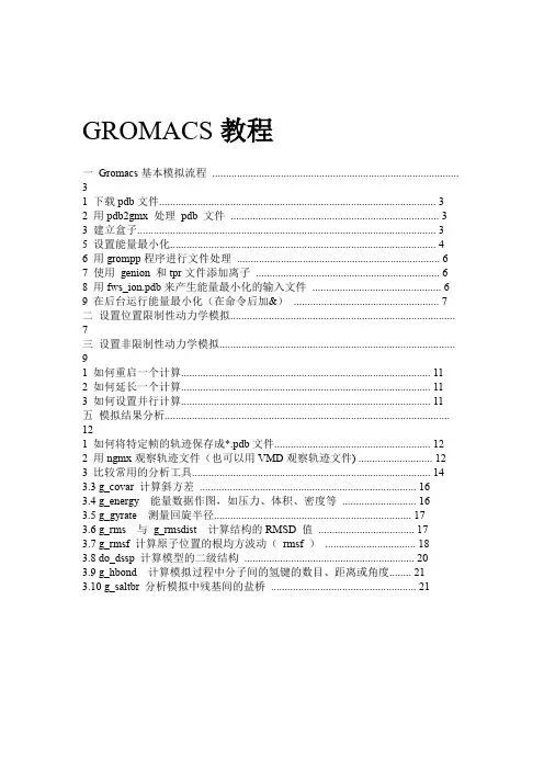
GROMACS教程一Gromacs基本模拟流程 (3)1 下载pdb文件 (3)2 用pdb2gmx 处理pdb 文件 (3)3 建立盒子 (3)5 设置能量最小化 (4)6 用grompp程序进行文件处理 (6)7 使用genion 和tpr文件添加离子 (6)8 用fws_ion.pdb来产生能量最小化的输入文件 (6)9 在后台运行能量最小化(在命令后加&) (7)二设置位置限制性动力学模拟 (7)三设置非限制性动力学模拟 (9)1 如何重启一个计算 (11)2 如何延长一个计算 (11)3 如何设置并行计算 (11)五模拟结果分析........................................................................................................121 如何将特定帧的轨迹保存成*.pdb文件 (12)2 用ngmx观察轨迹文件(也可以用VMD观察轨迹文件) (12)3 比较常用的分析工具 (14)3.3 g_covar 计算斜方差 (16)3.4 g_energy 能量数据作图,如压力、体积、密度等 (16)3.5 g_gyrate 测量回旋半径 (17)3.6 g_rms 与g_rmsdist 计算结构的RMSD 值 (17)3.7 g_rmsf 计算原子位置的根均方波动(rmsf ) (18)3.8 do_dssp 计算模型的二级结构 (20)3.9 g_hbond 计算模拟过程中分子间的氢键的数目、距离或角度 (21)3.10 g_saltbr 分析模拟中残基间的盐桥 (21)1GROMACS 是一个使用经典分子动力学理论研究蛋白质动力学的高端的高效的工具。
GROMACS是遵守GNU许可的免费软件,可以从以下站点下载:,并且可以在linux和Windows上使用。
在本教程中,将研究一个从漏斗形蜘蛛的毒液中分离的毒素。
![科技运[2008]113号_CTCS-3级列控系统功能需求规范(FRS)(V1.0)内容](https://uimg.taocdn.com/60be0ac6d5bbfd0a7956737b.webp)
CTCS-3级列控系统标准规范系列科技运[2008] 113号CTCS-3级列控系统功能需求规范(FRS)(V1.0)V1.0目录修改记录 (1)目录 (2)参考文献 (6)1序言 (7)2适用范围 (8)3总体要求 (9)3.1基本功能 (9)3.2应用等级要求 (9)3.3运用状态 (10)3.4配置参数(O) (11)3.5默认值 (12)4功能 (13)4.1行车功能 (13)4.1.1车载设备的自检 (13)4.1.2列车参数和司机参数的输入 (13)4.1.3调车状态 (15)4.1.4部分监控状态 (15)4.1.5完全监控状态 (16)4.1.6隔离状态 (16)4.1.7机车信号状态 (17)4.2与地面设备有关的功能 (17)4.2.1基础数据采集 (17)第2页 CTCS-3级列控系统功能需求规范(FRS)V1.04.2.3驶入可能有车占用区段的监控(引导状态) (18)4.2.4轨道占用检查 (18)4.2.5临时限速 (18)4.3车载设备功能 (18)4.3.1静态速度曲线的计算 (18)4.3.2动态速度曲线的计算 (19)4.3.3开口速度计算 (19)4.3.4列车定位 (19)4.3.5速度计算和显示 (20)4.3.6DMI显示 (20)4.3.7行车许可和速度限制的监控 (20)4.3.8溜逸和退行防护 (21)4.3.9车载设备信息记录 (21)4.4特殊行车 (22)4.4.1使用重联控制装置的多机牵引(O) (22)4.4.2无重联控制装置的多机牵引(O) (22)4.4.3列车退行(O) (23)4.5事故或其它系统(CTCS以外)故障时的功能要求 (23)4.5.1按照行车规则要求限速通过停车信号(目视行车状态) (23)4.6防护功能 (24)4.6.1紧急停车 (24)4.6.2进路适合性防护 (24)4.7与调度集中控制中心有关的功能 (25)4.7.1列车识别 (25)4.7.2列车的地理位置(O) (25)4.8附加功能 (25)4.8.1自动过分相控制(受电弓和供电系统控制) (25)4.8.2气密控制(O) (25)4.8.3纯文本消息 (25)4.8.4固定文本消息 (26)4.8.5特殊制动的管理(O) (26)4.8.6无线列调频点切换(O) (26)4.9与RBC有关的主要功能 (26)4.9.1列车完整性(O) (26)4.9.2RBC区域调车 (26)4.9.3RBC区域的行车许可 (27)4.9.4发送给RBC的列车参数 (27)4.9.5行车许可的缩短/撤销 (28)4.9.6退行(O) (28)4.9.7RBC切换 (28)5故障和降级 (30)5.1GSM-R通信中断 (30)5.2车载设备故障 (30)5.3RBC故障 (30)5.4RBC与车站联锁设备通信故障 (31)参考文献下列标准和规范所包含的条文,通过在本规范中引用而构成本规范的条文。

力控ForceCon平台封面力控科技ForceCon一体化平台介绍力控ForceCon平台覆盖整个工业信息化领域,通过分布式实时数据库的特点实现系统间的高效集成、级联及扩容,可为企业用户提供一个快速/高效的平台,满足各种工业信息化企业需求。
力控ForceCon平台以“分布式实时数据库”为核心搭建力控家族“工业控制消息总线”,并支持集成面向服务(SOA)系统架构的“信息服务总线”。
消息总线和服务总线提供可靠通用的信息交互机制和广域服务机制,实现整个系统间的安全高效的数据通信和应用集成。
贯穿整个企业信息化业务,可以自由构建不同规模的应用,实现从底层工业现场控制(小型场站系统、嵌入式HMI)、到生产调度指挥管理(SCADA)及上层信息化管理(MES、ERP)的融合,也可以完全拥抱工业大数据和云计算所带来的可扩展性,创建混合解决方案将数据推向云端的并保证其完整性,起到企业信息化融合作用。
力控ForceCon一体化平台:SCADA平台组态软件eForceConV5.0企业级实时历史数据库pSpaceV6.1智能生产信息门户集成平台FinforWorxV2.0工业智能报警平台FAlarmV2.0 计算引擎软件FcyberV2.0工业安全隔离网关pSafetylink 工业防火墙HC-ISG力控SCADA平台软件eForceCon V5.0力控SCADA平台软件eForceCon是力控科技为企业用户的工业信息化应用提供的一个基础软件平台,该SCADA平台的设计涵盖从现场监控站到调度中心,为企业提供从下到上的完整的生产信息采集与集成服务,从而为企业综合自动化、工厂数字化及完整的“管控一体化”的解决方案提供支撑平台。
分布式实时数据库核心设计以分布式实时数据库为核心,构建大型SCADA系统✧符合“工厂数字化模型”设计✧分层设计与管理✧数据四元组数据完整性保障✧多数据源管理模式,方便集成灵活的系统架构从单用户的系统到服务器/客户端、Web、冗余等混合应用的大型系统,系统架构可由用户自由设计。
![[航空航天]VF-300用户手册A4](https://uimg.taocdn.com/213fbe342e60ddccda38376baf1ffc4ffe47e2d7.webp)

A. Introduction1.Title: System Performance Following Loss of Two or More Bulk Electric SystemElements (Category C)2.Number: TPL-003-0a3.Purpose: System simulations and associated assessments are needed periodically to ensurethat reliable systems are developed that meet specified performance requirements, withsufficient lead time and continue to be modified or upgraded as necessary to meet present andfuture System needs.4.Applicability:4.1.Planning Authority4.2.Transmission Planner5.Effective Date: April 23, 2010B. RequirementsR1.The Planning Authority and Transmission Planner shall each demonstrate through a valid assessment that its portion of the interconnected transmission systems is planned such that thenetwork can be operated to supply projected customer demands and projected Firm (non-recallable reserved) Transmission Services, at all demand Levels over the range of forecastsystem demands, under the contingency conditions as defined in Category C of Table I(attached). The controlled interruption of customer Demand, the planned removal ofgenerators, or the Curtailment of firm (non-recallable reserved) power transfers may benecessary to meet this standard. To be valid, the Planning Authority and Transmission Planner assessments shall:R1.1.Be made annually.R1.2.Be conducted for near-term (years one through five) and longer-term (years six through ten) planning horizons.R1.3.Be supported by a current or past study and/or system simulation testing thataddresses each of the following categories, showing system performance followingCategory C of Table 1 (multiple contingencies). The specific elements selected (fromeach of the following categories) for inclusion in these studies and simulations shallbe acceptable to the associated Regional Reliability Organization(s).R1.3.1.Be performed and evaluated only for those Category C contingencies thatwould produce the more severe system results or impacts. The rationale forthe contingencies selected for evaluation shall be available as supportinginformation. An explanation of why the remaining simulations wouldproduce less severe system results shall be available as supportinginformation.R1.3.2.Cover critical system conditions and study years as deemed appropriate bythe responsible entity.R1.3.3.Be conducted annually unless changes to system conditions do not warrantsuch analyses.R1.3.4.Be conducted beyond the five-year horizon only as needed to addressidentified marginal conditions that may have longer lead-time solutions.R1.3.5.Have all projected firm transfers modeled.R1.3.6.Be performed and evaluated for selected demand levels over the range offorecast system demands.R1.3.7.Demonstrate that System performance meets Table 1 for Category Ccontingencies.R1.3.8.Include existing and planned facilities.R1.3.9.Include Reactive Power resources to ensure that adequate reactive resourcesare available to meet System performance.R1.3.10.Include the effects of existing and planned protection systems, including anybackup or redundant systems.R1.3.11.Include the effects of existing and planned control devices.R1.3.12.Include the planned (including maintenance) outage of any bulk electricequipment (including protection systems or their components) at thoseDemand levels for which planned (including maintenance) outages areperformed.R1.4.Address any planned upgrades needed to meet the performance requirements ofCategory C.R1.5.Consider all contingencies applicable to Category C.R2.When system simulations indicate an inability of the systems to respond as prescribed in Reliability Standard TPL-003-0_R1, the Planning Authority and Transmission Planner shall each: R2.1.Provide a written summary of its plans to achieve the required system performance as described above throughout the planning horizon:R2.1.1.Including a schedule for implementation.R2.1.2.Including a discussion of expected required in-service dates of facilities.R2.1.3.Consider lead times necessary to implement plans.R2.2.Review, in subsequent annual assessments, (where sufficient lead time exists), the continuing need for identified system facilities. Detailed implementation plans are notneeded.R3.The Planning Authority and Transmission Planner shall each document the results of these Reliability Assessments and corrective plans and shall annually provide these to its respectiveNERC Regional Reliability Organization(s), as required by the Regional ReliabilityOrganization.C. MeasuresM1.The Planning Authority and Transmission Planner shall have a valid assessment and corrective plans as specified in Reliability Standard TPL-003-0_R1 and TPL-003-0_R2.M2.The Planning Authority and Transmission Planner shall have evidence it reported documentation of results of its reliability assessments and corrective plans per ReliabilityStandard TPL-003-0_R3.D. Compliancepliance Monitoring Processpliance Monitoring ResponsibilityCompliance Monitor: Regional Reliability Organizations.pliance Monitoring Period and Reset TimeframeAnnually.1.3.Data RetentionNone specified.1.4.Additional Compliance InformationNone.2.Levels of Non-Compliance2.1.Level 1: Not applicable.2.2.Level 2: A valid assessment and corrective plan for the longer-term planning horizonis not available.2.3.Level 3: Not applicable.2.4.Level 4: A valid assessment and corrective plan for the near-term planning horizon isnot available.E. Regional Differences1.None identified.Version HistoryTable I. Trans mis s ion Sys tem Stand ards– Norm al and Em ergenc y Conditio nsa) Applicable rating refers to the applicable Normal and Emergency facility thermal Rating or system voltage limit as determined and consistently applied by the system or facility owner. Applicable Ratings may include Emergency Ratings applicable for short durations as required to permit operating steps necessary to maintain system control. All Ratings must be established consistent with applicable NERC Reliability Standards addressing Facility Ratings.b) Planned or controlled interruption of electric supply to radial customers or some local Network customers, connected to or supplied by the Faulted element or by the affected area, may occur in certain areas without impacting the overall reliability of the interconnected transmission systems. To prepare for the next contingency, system adjustments are permitted, including curtailments of contracted Firm (non-recallable reserved) electric power Transfers.c) Depending on system design and expected system impacts, the controlled interruption of electric supply to customers (load shedding), the planned removal from service of certain generators, and/or the curtailment of contracted Firm (non-recallable reserved) electric power transfers may be necessary to maintain the overall reliability of the interconnected transmission systems.d) A number of extreme contingencies that are listed under Category D and judged to be critical by the transmission planning entity(ies) will be selected for evaluation. It is not expected that all possible facility outages under each listed contingency of Category D will be evaluated.e) Normal clearing is when the protection system operates as designed and the Fault is cleared in the time normally expected with proper functioning of the installed protection systems. Delayed clearing of a Fault is due to failure of any protection system component such as a relay, circuit breaker, or current transformer, and not because of an intentional design delay.f) System assessments may exclude these events where multiple circuit towers are used over short distances (e.g., station entrance, river crossings) in accordance with Regional exemption criteria.Appendix 1Interpretation of TPL-002-0 Requirements R1.3.2 and R1.3.12 and TPL-003-0 Requirements R1.3.2 and R1.3.12 for Ameren and MISONERC received two requests for interpretation of identical requirements (Requirements R1.3.2 andR1.3.12) in TPL-002-0 and TPL-003-0 from the Midwest ISO and Ameren. These requirements state:Requirement R1.3.2Request for Interpretation of TPL-002-0 and TPL-003-0 Requirement R1.3.2Received from Ameren on July 25, 2007:Ameren specifically requests clarification on the phrase, ‘critical system conditions’ in R1.3.2. Ameren asks if compliance with R1.3.2 requires multiple contingent generating unit Outages as part of possible generation dispatch scenarios describing critical system conditions for which the system shall be planned and modeled in accordance with the contingency definitions included in Table 1.Request for Interpretation of TPL-002-0 and TPL-003-0 Requirement R1.3.2Received from MISO on August 9, 2007:MISO asks if the TPL standards require that any specific dispatch be applied, other than one that is representative of supply of firm demand and transmission service commitments, in the modeling of system contingencies specified in Table 1 in the TPL standards.MISO then asks if a variety of possible dispatch patterns should be included in planning analyses including a probabilistically based dispatch that is representative of generation deficiency scenarios, would it be an appropriate application of the TPL standard to apply the transmission contingency conditions in Category B of Table 1 to these possible dispatch pattern.The following interpretation of TPL-002-0 and TPL-003-0 Requirement R1.3.2 was developed by the NERC Planning Committee on March 13, 2008:The selection of a credible generation dispatch for the modeling of critical system conditions is within the discretion of the Planning Authority. The Planning Authority was renamed “Planning Coordinator” (PC) in the Functional Model dated February 13, 2007. (TPL -002 and -003 use the former “Planning Authority” name, and the Functional Model terminology was a change in name only and did not affect responsibilities.)−Under the Functional Model, the Planning Coordinator “Provides and informs Resource Planners, Transmission Planners, and adjacent Planning Coordinators of the methodologies and tools for the simulation of the transmission system” while the Transmission Planner “Receives from the Planning Coordinator methodologies and tools for the analysis and development of transmission expansion plans.” A PC’s selection of “critical system conditions” and its associated generation dispatch falls within the purview of “methodology.”Furthermore, consistent with this interpretation, a Planning Coordinator would formulate critical system conditions that may involve a range of critical generator unit outages as part of the possible generator dispatch scenarios.Both TPL-002-0 and TPL-003-0 have a similar measure M1:M1. The Planning Authority and Transmission Planner shall have a valid assessment and corrective plans as specified in Reliability Standard TPL-002-0_R1 [or TPL-003-0_R1]and TPL-002-0_R2 [or TPL-003-0_R2].”The Regional Reliability Organization (RRO) is named as the Compliance Monitor in both standards. Pursuant to Federal Energy Regulatory Commission (FERC) Order 693, FERC eliminated the RRO as the appropriate Compliance Monitor for standards and replaced it with the Regional Entity (RE). See paragraph 157 of Order 693. Although the referenced TPL standards still include the reference to the RRO, to be consistent with Order 693, the RRO is replaced by the RE as the Compliance Monitor for this interpretation. As the Compliance Monitor, the RE determines what a “valid assessment” means when evaluating studies based upon specific sub-requirements in R1.3 selected by the Planning Coordinator and the Transmission Planner. If a PC has Transmission Planners in more than one region, the REs must coordinate among themselves on compliance matters.Requirement R1.3.12Request for Interpretation of TPL-002-0 and TPL-003-0 Requirement R1.3.12Received from Ameren on July 25, 2007:Ameren also asks how the inclusion of planned outages should be interpreted with respect to the contingency definitions specified in Table 1 for Categories B and C. Specifically, Ameren asks if R1.3.12 requires that the system be planned to be operated during those conditions associated with planned outages consistent with the performance requirements described in Table 1 plus any unidentified outage. Request for Interpretation of TPL-002-0 and TPL-003-0 Requirement R1.3.12Received from MISO on August 9, 2007:MISO asks if the term “planned outages” means only already known/scheduled planned outages that may continue into the planning horizon, or does it include potential planned outages not yet scheduled that may occur at those demand levels for which planned (including maintenance) outages are performed?If the requirement does include not yet scheduled but potential planned outages that could occur in the planning horizon, is the following a proper interpretation of this provision?The system is adequately planned and in accordance with the standard if, in order for a system operator to potentially schedule such a planned outage on the future planned system, planning studies show that a system adjustment (load shed, re-dispatch of generating units in the interconnection, or system reconfiguration) would be required concurrent with taking such a planned outage in order to prepare for a Category B contingency (single element forced out of service)? In other words, should the system in effect be planned to be operated as for a Category C3 n-2 event, even though the first event is a planned base condition?If the requirement is intended to mean only known and scheduled planned outages that will occur or may continue into the planning horizon, is this interpretation consistent with the original interpretation by NERC of the standard as provided by NERC in response to industry questions in the Phase I development of this standard1?The following interpretation of TPL-002-0 and TPL-003-0 Requirement R1.3.12 was developed by the NERC Planning Committee on March 13, 2008:This provision was not previously interpreted by NERC since its approval by FERC and other regulatory authorities. TPL-002-0 and TPL-003-0 explicitly provide that the inclusion of planned (including maintenance) outages of any bulk electric equipment at demand levels for which the planned outages are required. For studies that include planned outages, compliance with the contingency assessment for TPL-002-0 and TPL-003-0 as outlined in Table 1 would include any necessary system adjustments which might be required to accommodate planned outages since a planned outage is not a “contingency” as defined in the NERC Glossary of Terms Used in Standards.。
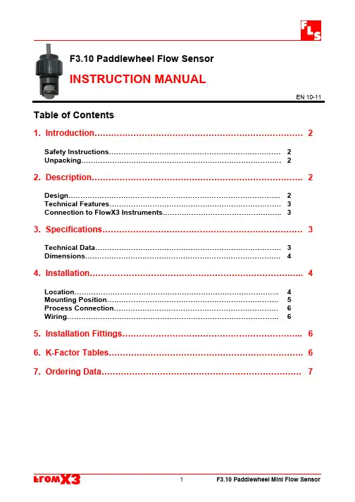
F3.10Paddlewheel Flow SensorINSTRUCTION MANUALEN10-11 Table of Contents1.Introduction (2)Safety Instructions (2)Unpacking (2)2.Description (2)Design (2)Technical Features (3)Connection to FlowX3Instruments (3)3.Specifications (3)Technical Data (3)Dimensions (4)4.Installation (4)Location (4)Mounting Position (5)Process Connection (6)Wiring (6)5.Installation Fittings (6)6.K-Factor Tables (6)7.Ordering Data (7)1.Introduction1.1.Safety InstructionsGeneral Statements❑The sensor F3.10.H.0X has only been designed to measure the flow of liquids.❑Do not install and service the sensor without following the Instruction Manual.❑This sensor is designed to be connected to other instruments which can be hazardous if used improperly.Read and follow all associated instrumentmanuals before using with this sensor.❑Sensor installation and wiring connections should only be performed by qualified staff.❑Do not modify product construction.Installation and Commissioning Statements❑Remove power to the sensor before wiring any connection.❑Depressurize and vent the system before installing or removing the sensor.❑Check and confirm the chemical compatibility of the materials in contact with the liquid.❑Do not exceed maximum temperature/pressure data.❑To clean the sensor,use only chemical compatible products.1.2.UnpackingPlease verify that the product is complete and without any damage.The following items must be included:∙F3.10Paddlewheel Flow Sensor∙Instruction Manual for F3.10Flow Sensor2.Description2.1.DesignThe simple and reliable paddlewheel flow sensor type F3.10is designed for use with every kind of solid-free liquids.The sensor can measure flow from0.25m/s(0.8ft/s) producing a frequency output signal highly repeatable.A rugged construction and a proven technology guarantee exceptional performances with little or no maintenance required.A specially designed family of fittings ensures an easy and quick installation into all pipe materials in sizes from DN15to DN40(0.5to1.5in.).2.2.Connections to FlowX3InstrumentsStrumento FlowX3F9.00F9.01F9.02F9.03F9.20F9.50F9.51SensoreFlowX3F3.10.H X X X X X X3.Specifications3.1.Technical DataGeneralPipe Size Range:DN15to DN40(0.5to11/2in.).Refer to Installation Fittings section for more detailsFlow Rate Range:0.25to4m/s(0.8to12,5ft./s)Linearity:±1%of full scaleRepeatability:±0.5%of full scaleMinimum Reynolds Number Required:4500Enclosure:IP68Operating Pressure:max10bar(145psi)@20°C(68°F)max2bar(30psi)@70°C(158°F)Wetted Materials:Sensor Body:ABSO-rings:EPDM or FPMRotor:ABSShaft:AISI316LElectricalSupply voltage:5to24VDC regulatedSupply current:<30mA@24VDCOutput signal:∙square wave∙Output frequency:15Hz per m/s nominal(4,6Hz per ft/s nominal)∙Output type:transistor NPN open collector∙Output current:10mA max.Cable length:2m(6,5ft)standard,300m(990ft)maximumStandards&ApprovalsManufactured under ISO9002and14001CE3.2.DimensionsF3.00IP68Remote SensorLength=41mm(1,6”)Width=20mm(0,8”)Cap=¾”4.Installation4.1.LocationDifferent pipe configurations and obstacles in the flow line such as valves,elbows,pipe bends and strainers create variations on the flow profile.Whenever possible follow the EN ISO5167-1installation recommendations to locate the sensor.Always maximize distance between flow sensor and pump.4.2.Mounting PositionMake sure the pipeline is always full.❑Horizontal pipe runs:Fig.1:installation with no sediments presentFig.2:installation with no air bubbles presentFig.3:installation if sediments or air bubbles may be present❑Vertical pipe runs:Install sensor in any orientation.Upward flow is preferred to ensure full pipe.4.3.Process Connection1.Lubricate the sensor O-rings with asilicone lubricant.Do not use anypetroleum based lubricant that maydamage the O-rings.2.Lower the sensor into the fittingmaking sure the alignment tab isseated in the fitting notch.3.Hand tighten the sensor cap.Do notuse any tool otherwise cap and/orfitting threads may be damaged.N.B The plastic Tees must be installed with the arrow in according to the flow direction.Flow direction4.4.Wiring❑Always ensure the power supply is switched off before working on the sensor.❑Always use a high quality(regulated)DC voltage supply.F3.10.H IP68Sensor Connection F3.10.H IP68Sensor Connectionto FlowX3Instruments to Other Brand Instruments∙2to10Kohm Pull-up resistor may be required. 5.Installation FittingsType DescriptionPlastic Tees∙Size:D20to D50(0.5”to1.5”)∙Materials:PVC,CPVC6.K-Factor TablesK-Factor is the number of pulses a sensor produces for one liter of fluid measured.Here all K-Factors for water at ambient temperature are listed.K-Factor values can depend upon the installation conditions.Please contact your dealer for K-Factor values not included in the tables. Installation on PVC pipesISO Metric PVC Tee Fittings for ISO SDR21pipes(female ends for solvent welding)Part No.DN d K-FactorTMIV201520113,61TMIV25202561,06TMIV32253235,56TMIV40324020,44TMIV50405011,787.Ordering DataFlowX3F3.00.X.XX (Remote version)Part No.VersionPower supply LengthBodyO-ringsEnclosureF3.10.H.01Hall 5-24VDC 41mm ABS EPDM IP68F3.10.H.02Hall5-24VDC41mmABSFPMIP68Spare Parts ItemPart No.NameDescriptionA-1F3.SP2.1Sensor Cap Gray Sensor Cap A-2F3.SP3.1O-Rings EPDM Sensor body O-rings A-3F3.SP3.2O-Rings FPM Sensor body O-rings A-4F3.SP4Rotor KIT ABS rotor with AISI 316L ShaftF3.SP5.1Sensor Plug ABS Sensor PlugF3.SP6Electrical cableCable (per meter),3cond.,22AWGF.I.P.Formatura Iniezione Polimeri S.p.A.Loc.Pian di Parata,16015Casella (GE)–Italy Tel +3901096211–Fax +390109621209A-1A-2or A-3A-4。
i s c l a i m er : T h i s d o c u m e n t a t i o n i s n o t i n t e n d e d a s a s u b s t i t u t e f o r a n d i s n o t t o b e u s e d f o r d e t e r m i n i n g s u i t a b i l i t y o r r e l i a b i l i t y o f t h e s e p r o d u c t s f o r s p e c i f i c u s e r a p p l i c a t i o n sProduct data sheetCharacteristicsTSXCAY33motion control modules - for servomotors - 8ms..10 s - 3 axisProduct availability : Stock - Normally stocked in distribution facilityPrice* : 7820.00 USDMainRange of productModicon Premium Automation platform Product or component type Motion control modules Product specific application For servo motorsServo loop type Proportional to overshoot compensation and gain switching 4 ms ChecksConsistency of commandsEncoder coupling, servo drive present, emergency stop Proper execution of movement Sensor power supply Validity of parametersPresence of voltage/sensor feedback counter inputComplementarySpeed profile path Trapezoidal or parabolic Resolution >= 0.5 position units per point <= 1000 position units per point Length of axis 256...32000000 P Acquisition speed <= 270000 points/mn >= 54000 points/mn Acceleration time 8 ms...10 s Operating modeOFFDirect drive mode Manual Automatic FOLLOWERType of axis 2/3 axis linear interpolation Limited axis I/O modularity 3 axesInput compatibilityAbsolute encoder SSI output 12...25 bits Incremental encoder 10...30 V totem pole Incremental encoder 5 V DC RS422With 2-wire/3-wire sensor (24 DC) auxiliary inputAbsolute encoder parallel output ABE7CPA11Clock frequency200 kHz SSI absolute encoderIncremental encoder frequency x1500 kHzIncremental encoder frequency x 41000 kHz in counting250 kHz in inputPower dissipation in W10...17 WInput type Current sink auxiliary input conforming to EN/IEC 1131 Type 2Resistive counter inputResistive servo drive control input conforming to EN/IEC 1131 Type 1 Input logic PositiveInput voltage24 V 8 mA auxiliary input24 V 8 mA servo drive control input5 V 18 mA counter inputInput voltage limits<= 5.5 V counter input19...30 V auxiliary input19...30 V servo drive control inputVoltage state 1 guaranteed>= 11 V auxiliary input>= 11 V servo drive control input>= 2.4 V counter inputCurrent state 1 guaranteed>= 3.5 mA servo drive control input>= 3.7 mA counter input>= 6 mA auxiliary inputVoltage state 0 guaranteed<= 1.2 V auxiliary input<= 1.2 V counter input<= 5 V servo drive control inputCurrent state 0 guaranteed<= 1 mA counter input<= 1.5 mA servo drive control input<= 1 mA auxiliary inputInput impedance270 Ohm counter input3000 Ohm auxiliary input3000 Ohm servo drive control inputNumber of outputs 3 analogue output static3 reflex output static conforming to EN/IEC 611313 servo drive validation output relayAnalogue output range+/- 10...24 VAnalogue output resolution13 bits + signLSB value 1.25 mV analogue outputOutput voltage24 V DC reflex output24 V DC servo drive validation outputOutput voltage limits19...30 V reflex output5...30 V servo drive validation outputNominal output current0.5 A reflex outputMaximum output current 1.5 mA analogue output200 mA servo drive validation output625 mA reflex outputMinimum load 1 mA 1 VVoltage drop< 1 V at state on reflex outputLeakage current< 0.3 mA reflex outputSwitching time< 5 ms for servo drive validation< 500 µs for reflex outputOutput compatibility Positive logic DC inputs (resistance <= 15 kOhm) reflexShort-circuit protection Current limiter reflex outputThermal tripping reflex outputOutput overload protection Current limiter reflex outputThermal tripping reflex outputOutput overvoltage protection Zener diode between outputs and 24 DC reflex outputReverse polarity protection Reverse diode on supply reflex outputLocal signalling 1 LED green module operating (RUN)1 LED red external fault (I/O)1 LED red internal fault, module failure (ERR)3 LEDs green axis diagnostics availableElectrical connection1 connector HE-10 20 pins for servo drive ctrl inputs + for ext power supply of servo drive inputs/outputs1 connector SUB-D 9 for an analogue output (speed reference)2 connectors HE-10 20 pins for aux inputs, reflex output, for external sensor and preactuator power supply3 connectors SUB-D 15 for an incremental or absolute encoder Current consumption1500 mA 5 V DC 30 mA 24 V DC22...40 mA 24 V DC on 10/30 V absolute encoder module Module format DoubleProduct weight1.34 lb(US) (0.61 kg)EnvironmentProtective treatmentTCAmbient air temperature for operation 32...140 °F (0...60 °C)Ambient air temperature for storage -13...158 °F (-25...70 °C)Relative humidity 5...95 % without condensation Operating altitude<= 6561.68 ft (2000 m)Ordering and shipping detailsCategory22558 - TSX PREMIUM, ATRIUM & PL7 PRO Discount Schedule PC22GTIN00785901105701Nbr. of units in pkg.1Package weight(Lbs) 2.21Returnability N Country of originFROffer SustainabilitySustainable offer status Not Green Premium productRoHS (date code: YYWW)Compliant - since 0804 - Schneider Electric declaration of conformity Schneider Electric declaration of conformity REAChReference not containing SVHC above the threshold Reference not containing SVHC above the threshold Product end of life instructionsNeed no specific recycling operationsContractual warrantyWarranty period18 monthsDimensions DrawingsStandard and Extendable Racks for Modules MountingDimensions of Modules and Racks(1) With screw terminal block modules.(2) Maximum depth for all types of modules and their associated connectors.Connection of Speed Reference Signals Connector PinoutConnection of Counting SignalsConnectors PinoutsConnection of Sensors/Pre-actuators and Encoder Power Supply, without Variable Speed ControllerHE10 Connector PinoutThe auxiliary inputs/outputs are allocated the following functions:●I0 = cam reference point input,●I1 =emergency stop input (stop if there is no current in the input),●I2 = adjusting input,●I3 = adjustment input,●Q0 = reflex output (static output),●0 V = shared auxiliary inputs and reflex outputs.Connection of the Variable Speed Controller Signals Connector PinoutThe axis command modules implement basic management of the signals necessary for correct operation of the variable speed controllers. Thereis only one connector, regardless of the number of axis command module channels.COMx – VALVARx: potential free contact to validate variable speed controller OK_VARx: variable speed controller input check 24 V – 0 V sensor power supplyNOTE: Each channel uses a potential free closing contact.。
力控科技:ForceCon一体化平台助力用户实现智能化曹银平【期刊名称】《自动化博览》【年(卷),期】2016(000)011【总页数】2页(P26-27)【作者】曹银平【作者单位】【正文语种】中文始建于20世纪90年代初的北京力控元通科技有限公司(以下简称力控科技),历经二十多年的发展,已从被动地适应产业环境,发展成为工业软件领域的影响者和培育者。
立足于力控ForceCon产品家族,为用户提供具有国际竞争力的工业自动化软件产品和服务。
力控科技以信息化促进自动化,希望通过多年的行业实践与经验积累,结合现代企业业务模型,为客户提供以力控ForceCon产品家族为核心的从生产现场到调度管理指挥以及企业管理信息化完整的产品体系及解决方案,助力中国制造业实现转型升级。
据力控科技自动化软件营销板块总经理门杰介绍,力控科技ForceCon平台覆盖整个工业信息化领域,以“分布式实时数据库”为核心,实现从底层工业现场控制(小型场站系统、嵌入式HMI)、到生产调度指挥管理(SCADA)及上层信息化管理(MES、ERP)的融合,也可以完全拥抱工业大数据和云计算所带来的可扩展性,创建混合解决方案将数据推向云端并保证其完整性,可通过综合利用ForceCon平台建设信息系统帮助企业完成数字化、智能化转型,建设智能工厂生态系统。
他特别谈到,力控科技每年将销售的20%用于新技术、新产品的研发,如今,力控ForceCon一体化平台从异构设备集成互联、信息物理技术融合、精益生产管理、综合信息展示、工业大数据、数字化车间虚拟镜像、工业信息安全等方面为用户提供产品及解决方案,帮助其提升企业生产过程的效率和产品的质量水平,从而实现智能工厂的建设。
中国经济尤其是工业的飞速发展,造成了信息化建设滞后及其发展的不平衡,照搬国外模式引进技术及产品往往不能从根本上解决问题,力控科技专家团队以实事求是的客观精神,全方位立足用户需求,注重信息化投资的持续效用和收益,帮助企业从全产业链生态视角来改变现有的生产思维和商业模式,推出基于工厂模型的工业软件平台助力用户构建高度灵活的个性化和一体化的智能制造体系。
Load Cells 201 General Procedures for theUse of Load Cells©1998–2009 Interface Inc. All rights reserved. Load Cells 201 Page 1Copyright 1998–2009, Interface Inc. All rights reserved.Interface, Inc. makes no warranty, either expressed or implied, including, but not limited to, any implied warranties of merchantability or fitness for a particular purpose, regarding these materials, and makes such materials available solely on an “as-is” basis.In no event shall Interface, Inc. be liable to anyone for special, collateral, incidental, or consequential damages in connection with or arising out of use of these materials.Interface, Inc.7401 Butherus DriveScottsdale, Arizona 85260480.948.5555 phone480.948.1924 fax**************************©1998–2009 Interface Inc. All rights reserved. Load Cells 201 Page 2Table of ContentsGENERAL PROCEDURES FOR THE USE OF LOAD CELLS (4)Excitation Voltage (4)Remote Sensing of Excitation Voltage (5)Physical Mounting: “Dead” and “Live” End (6)Mounting Procedures for Beam Cells (7)Mounting Procedures for Other Mini Cells (7)Mounting Procedures for Low Profile Cells With Bases (8)Mounting Procedures for Low Profile Cells Without Bases (9)Mounting Torques for Fixtures in Low Profile Cells (10)©1998–2009 Interface Inc. All rights reserved. Load Cells 201 Page 3©1998–2009 Interface Inc. All rights reserved. Load Cells 201 Page 4GENERAL PROCEDURES FOR THE USE OF LOAD CELLSExcitation VoltageInterface load cells all contain a full bridge circuit,which is shown in simplified form in Figure 1.Each leg is usually 350 ohms, except for the modelseries 1500 and 1923 which have 700 ohm legs.The preferred excitation voltage is 10 VDC, whichguarantees the user the closest match to theoriginal calibration performed at Interface. This isbecause the gage factor (sensitivity of the gages) isaffected by temperature. Since heat dissipation in the gages is coupled to the flexure through a thin epoxy glue line, the gages are kept at a temperature very close to the ambient flexure temperature. However, the higher the power dissipation in the gages, the farther the gage temperature departs from the flexure temperature. Referring to Figure 2, notice that a 350 ohm bridge dissipates 286 mw at 10 VDC. Doubling the voltage to 20 VDC quadruples the dissipation to 1143 mw, which is a large amount of power in the small gages and thus causes a substantial increase in the temperature gradient from the gages to the flexure. Conversely, halving the voltage to 5 VDC lowers the dissipation to 71 mw, which is not significantly less than 286 mw. Operating a Low Profile cell at 20 VDCwould decrease its sensitivity by about0.07% from the Interface calibration,whereas operating it at 5 VDC wouldincrease its sensitivity by less than 0.02%.Operating a cell at 5 or even 2.5 VDC inorder to conserve power in portableequipment is a very common practice.Certain portable data loggers electricallyswitch the excitation on for a very lowproportion of the time to conserve powereven further. If the duty cycle (percentageof “on” time) is only 5%, with 5 VDC excitation, the heating effect is a miniscule 3.6 mw, which could cause an increase insensitivity of up to 0.023% from the Interface calibration. Figure 1. Full bridge circuit.Figure 2. Dissipation versus excitation voltage (350 ohm bridge).©1998–2009 Interface Inc. All rights reserved.Load Cells 201 Page 5 Users having electronics which provide only AC excitation should set it to 10 VRMS, which would cause the same heat dissipation in the bridge gages as 10 VDC.Variation in excitation voltage can also cause a small shift in zero balance and creep. This effect is most noticeable when the excitation voltage is first turned on. The obvious solution for this effect is to allow the load cell to stabilize by operating it with 10 VDC excitation for the time required for the gagetemperatures to reach equilibrium. For critical calibrations this may require up to 30 minutes.Since the excitation voltage is usually well regulated to reduce measurement errors, the effects of excitation voltage variation are typically not seen by users except when the voltage is first applied to the cell.Remote Sensing of Excitation VoltageMany applications can make use of the four-wire connection shown in Figure 3. Thesignal conditioner generates a regulatedexcitation voltage, V x , which is usually 10VDC. The two wires carrying the excitationvoltage to the load cell each have a lineresistance, R w . If the connecting cable isshort enough, the drop in excitation voltagein the lines, caused by current flowingthrough R w , will not be a problem.Figure 4 shows the solution for the line dropproblem. By bringing two extra wires backfrom the load cell, we can connect the voltageright at the terminals of the load cell to thesensing circuits in the signal conditioner.Thus, the regulator circuit can maintain theexcitation voltage at the load cell precisely at10 VDC under all conditions.This six-wire circuit not only corrects for thedrop in the wires, but also corrects forchanges in wire resistance due totemperature. Figure 5 shows the magnitude ofthe errors generated by the use of the four-wire cable, for three common sizes of cables.The graph can be interpolated for other wiresizes by noting that each step increase in wiresize increases resistance (and thus line drop)by a factor of 1.26 times. The graph can alsobe used to calculate the error for differentcable lengths by calculating the ratio of theFigure 3. Four-wire connection.Figure 4. Six-wire remote sense connection. Figure 5. Line drop versus temperature for common cable sizes.©1998–2009 Interface Inc. All rights reserved. Load Cells 201 Page 6length to 100 feet, and multiplying that ratio times the value from the graph. The temperature range of the graph may seem broader than necessary, and that is true for most applications. However, consider a #28AWG cable which runsmostly outside to a weigh station in winter, at 20 degrees F. When the sun shines on the cable in summer, the cable temperature could rise to over 140 degrees F. The error would rise from –3.2% RDG to –4.2% RDG, a shift of –1.0% RDG. If the load on the cable is increased from one load cell to four load cells, the drops would be four times worse. Thus, for example, a 100-foot #22AWG cable would have an error at 80 degrees F of (4 x 0.938) = 3.752% RDG.These errors are so substantial that standard practice for all multiple-cellinstallations is to use a signal conditioner having remote sense capability, and to use a six-wire cable out to the junction box which interconnects the four cells. Keeping in mind that a large truck scale could have as many as 16 load cells, it is critical to address the issue of cable resistance for every installation.Simple rules of thumb which are easy to remember:1. The resistance of 100 feet of #22AWG cable (both wires in the loop) is3.24 ohms at 70 degrees F.2. Each three steps in wire size doubles the resistance, or one step increasesthe resistance by a factor of 1.26 times.3. The temperature coefficient of resistance of annealed copper wire is 23%per 100 degrees F.From these constants it is possible to calculate the loop resistance for any combination of wire size, cable length, and temperature.Physical Mounting: “Dead” and “Live” EndAlthough a load cell will function no matter how it isoriented and whether it is operated in tension mode orcompression mode, mounting the cell properly is veryimportant to ensure that the cell will give the moststable readings of which it is capable.All load cells have a “dead” end and a “live” end. Thedead end is defined as the mounting end which isdirectly connected to the output cable or connector by solid metal, as shown by the heavy arrow inFigure 6. Conversely, the live end is separated from the output cable or connector by the gage area of the flexure.This concept is significant, because mounting a cell on its live end makes itsubject to forces introduced by moving or pulling the cable, whereas mounting it on the dead end ensures that the forces coming in through the cable are shunted to the mounting instead of being measured by the load cell.Figure 6. Loading ends of S-cell.©1998–2009 Interface Inc. All rights reserved. Load Cells 201 Page 7Generally, the Interface nameplate readscorrectly when the cell is sitting on the deadend on a horizontal surface. Therefore, theuser can use the nameplate lettering to specifythe required orientation very explicitly to theinstallation team. As an example, for a singlecell installation holding a vessel in tensionfrom a ceiling joist, the user would specifymounting the cell so that the nameplate readsupside down. For a cell mounted on ahydraulic cylinder, the nameplate would readcorrectly when viewed from the hydrauliccylinder end. N OTECertain Interface customers have specified that their nameplatebe oriented upside down from normal practice. Use caution at acustomer’s installation until you are certain that you know thenameplate orientation situation.Mounting Procedures for Beam CellsBeam cells are mounted by machine screws or bolts through the two untapped holes at the dead end of the flexure. If possible, a flat washer should be used under the screw head to avoid scoring the surface of the load cell. All bolts should be Grade 5 up to #8 size, and Grade 8 for 1/4” or larger. Since all of the torques and forces are applied at the dead end of the cell, there is little risk that the cell will be damaged by the mounting process. However, avoid electric arc welding when the cell is installed, and avoid dropping the cell or hitting the live end of the cell. For mounting the cells:•MB Series cells use 8-32 machine screws, torqued to 30 inch-pounds •SSB Series cells also use 8-32 machine screws through 250 lbf capacity •For the SSB-500 use 1/4 - 28 bolts and torque to 60 inch-pounds (5 ft-lb) • For the SSB-1000 use 3/8 - 24 bolts and torque to 240 inch-pounds (20ft-lb)Mounting Procedures for Other Mini CellsIn contrast to the rather simple mounting procedure for beam cells, the other Mini Cells (SM, SSM, SMT, SPI, and SML Series) pose the risk of damage by applying any torque from the live end to the dead end, through the gaged area. Remember that the nameplate covers the gaged area, so the load cell looks like a solid piece of metal. For this reason, it is essential that installers are trained in the construction of Mini Cells so that they understand what the application of torque can do to the thin gaged area in the center, under the nameplate.Any time that torque must be applied to the cell, for mounting the cell itself or for installing a fixture onto the cell, the affected end should be held by an open end wrench or a Crescent wrench so that the torque on the cell can be reacted at Figure 7. Loading ends of Low Profile cell.©1998–2009 Interface Inc. All rights reserved. Load Cells 201 Page 8the same end where the torque is being applied. Itis usually good practice to install fixtures first,using a bench vise to hold the load cell’s live end,and then to mount the load cell on its dead end.This sequence minimizes the possibility thattorque will be applied through the load cell.Since the Mini Cells have female threaded holesat both ends for attachment, all threaded rods orscrews must be inserted at least one diameter intothe threaded hole, to ensure a strong attachment.In addition, all threaded fixtures should be firmlylocked in place with a jam nut or torqued down to a shoulder, to ensure firm thread contact. Loosethread contact will ultimately cause wear on theload cell’s threads, with the result that the cell will fail to meet specifications after long-time use.Threaded rod used to connect to Mini Series load cells larger than 500 lbf capacity should be heat treated to Grade 5 or better. One good way to get hardened threaded rod with rolled Class 3 threads is to use Allen drive set screws, which can obtained from any of the large catalog warehouses like McMaster-Carr or Grainger.For consistent results, hardware like rod end bearings and clevises can beinstalled at the factory by specifying the exact hardware, the rotation orientation, and the hole-to hole spacing on the purchase order. The factory is always pleased to quote the recommended and possible dimensions for attached hardware. Mounting Procedures for Low Profile Cells With BasesWhen a Low Profile cell is procured from the factory with the base installed, the mounting bolts around the periphery of the cell have been properly torqued and the cell has been calibrated with the base in place. The circular step on the bottom surface of the base is designed to direct the forces properly through the base and into the load cell. The base should be bolted securely to a hard, flat surface.If the base is to be mounted onto themale thread on a hydraulic cylinder,the base can be held from rotating byusing a spanner wrench. There arefour spanner holes around theperiphery of the base for this purpose.With regard to making the connectionto the hub threads, there are threerequirements which will ensure achieving the best results. Figure 8. Reacting mounting and installation torques. Figure 9. Using a spanner wrench to hold base from rotating.©1998–2009 Interface Inc. All rights reserved. Load Cells 201 Page 9Model Torque (ft-lb)Torque (N-m)1210571211571220456012212535123180105123212016012402503501241250350321057321157322045603221253542115742212535461157462125351. The part of the threaded rod which engages the load cell’s hub threadsshould have Class 3 threads, to provide the most consistent thread-to-thread contact forces.2. The rod should be screwed into the hub to the bottom plug, and thenbacked off one turn, to reproduce the thread engagement used during the original calibration.3. The threads must be engaged tightly by the use of a jam nut. The easiestway to accomplish this is to pull tension of130 to 140 percent of capacity on the cell, and then lightly set the jam nut. When the tension is released, the threads will be properly engaged. This method provides moreconsistent engagement than attempting to jam the threads by torquing the jam nut with no tension on the rod.In the event the customer does not have thefacilities for pulling enough tension to set thehub threads, a Calibration Adapter can also beinstalled in any Low Profile cell at the factory.This configuration will yield the best possibleresults, and will provide a male threadconnection which is not so critical as to themethod of connection.In addition, the end of the Calibration Adapteris formed into a spherical radius which alsoallows the cell to be used as a straightcompression cell. This configuration for compression mode is more linear andrepeatable than the use of a load button in auniversal cell, because the calibration adaptor can be installed under tension and jammed properly for more consistent thread engagement in the cell.Mounting Procedures for Low Profile Cells Without Bases The mounting of a Low Profile cell shouldreproduce the mounting that was used during thecalibration. Therefore, when it is necessary to mounta load cell on a customer-supplied surface, thefollowing five criteria should be strictly observed. 1. The mounting surface should be of a material having the same coefficient of thermal expansion as the load cell, and of similar hardness. For cells up through 2000 lbf capacity, use 2024 aluminum. For all larger cells, use 4041 steel, hardened to R c 33 to 37. 2. The thickness should be at least as thick asthe factory base normally used with the load cell. This does not mean that the cell willnot function with a thinner mounting, but the cell may not meet linearity, repeatability or hysteresis specifications on a thin mounting plate.Figure 10. Load cell with calibration adapter installed. Table 1. Mounting bolt torques.©1998–2009 Interface Inc. All rights reserved. Load Cells 201 Page 10 3. The surface should be ground to a flatness of 0.0002” T.I.R. lf the plateis heat treated after grinding, it is always worthwhile to give the surface one more light grind to ensure flatness.4. The mounting bolts should be Grade 8. If they can’t be obtained locally,they can be ordered from the factory. For cells with counterboredmounting holes, use socket head cap screws. For all other cells, use hex head bolts. Do not use washers under the bolt heads.5. First, tighten the bolts to 60% of the specified torque; next, torque to90%; finally, finish at 100%. The mounting bolts should be torqued in sequence, as shown in Figures 11, 12, and 13. For cells having 4mounting holes, use the pattern for the first 4 holes in the 8-hole pattern.Mounting Torques for Fixtures in Low Profile CellsThe torque values for mounting fixtures into the active ends of Low Profile load cells are not the same as the standard values found in tables for the materials involved. The reason for this difference is that the thin radial webs are the only structural members which restrain the center hub from rotating with relation to the periphery of the cell.The safest way to achieve a firm thread-to-thread contact without damaging the cell is to apply a tensile load of 130 to 140 % of the load cell’s capacity, set the jam nut firmly by applying a light torque to the jam nut, and then release the load.Torques on the hubs of Low Profile cells should be limited by the following equation:Where:allowed torque (in-Ib)Rated Capacity of the load cell (lbf)For example, the hub of a 1000 lbf Low Profile cell should not be subjected to more than 400 in-lb of torque.Figure 11. Mounting bolt torque sequence, 8 holes. Figure 12. Mounting bolt torque sequence, 12 holes. Figure 13. Mounting bolt torque sequence, 16 holes.C AUTIONApplication of excessive torque could shear the bond betweenthe edge of the sealing diaphragm and the flexure. It could alsocause a permanent distortion of the radial webs, which couldaffect the calibration but might not show up as a shift in the zerobalance of the load cell.©1998–2009 Interface Inc. All rights reserved. Load Cells 201 Page 11。