自动化系毕业设计外文翻译(中英文对照)
- 格式:doc
- 大小:102.00 KB
- 文档页数:10
中英文资料外文翻译文献外文原文Automating Manufacturing Systems with PLCs2.1 INTRODUCTIONControl engineering has evolved over time. In the past humans were the main method for controlling a system. More recently electricity has been used for control and early electrical control was based on relays. These relays allow power to be switched on and off without a mechanical switch. It is common to use relays to make simple logical control decisions. The development of low cost computer has brought the most recent revolution,the Programmable Logic Controller (PLC). The advent of the PLC began in the1970s, and has become the most common choice for manufacturing controls.PLCs have been gaining popularity on the factory floor and will probably remain predominant for some time to come. Most of this is because of the advantages they offer. • Cost effective for controlling complex systems.• Flexible and can be reapplied to control other systems quickly and easily.• Computational abilities allow more sophisticated control.• Tr ouble shooting aids make programming easier and reduce downtime.• Reliable components make these likely to operate for years before failure.2.1.1 Ladder logicLadder logic is the main programming method used for PLCs. As mentioned before, ladder logic has been developed to mimic relay logic. logic diagrams was a strategic one. By selecting ladder logic as the main programming method, the amount of retraining needed forengineers and trades people was greatly reduced.Modern control systems still include relays, but these are rarely used for logic. A relay is a simple device that uses a magnetic field to control a switch, as pictured in Figure 2.1. When a voltage is applied to the input coil, the resulting current creates a magnetic field. The magnetic field pulls a metal switch (or reed) towards it and the contacts touch, closing the switch. The contact that closes when the coil is energized is called normally open. The normally closed contacts touch when the input coil is not energized. Relays are normally drawn in schematic form using a circle to represent the input coil. The output contacts are shown with two parallel lines. Normally open contacts are shown as two lines, and will be open (non-conducting) when the input is not energized. Normally closed contacts are shown with two lines with a diagonal line through them. When the input coil is not energized the normally closed contacts will be closed (conducting).Figure 2.1 Simple Relay Layouts and SchematicsRelays are used to let one power source close a switch for another (often high current) power source, while keeping them isolated. An example of a relay in a simple control application is shown in Figure 2.2. In this system the first relay on the left is used as normally closed, and will allow current to flow until a voltage is applied to the input A. The second relay is normally open and will not allow current to flow until a voltage is applied to the input B. If current is flowing through the first two relays then current will flow through the coil in the third relay, and close the switch for output C. This circuit would normally be drawn in the ladder logic form. This can be read logically as C will be on if A is off and B is on.Figure 2.2 A Simple Relay ControllerThe example in Figure 2.2 does not show the entire control system, but only the logic. When we consider a PLC there are inputs, outputs, and the logic. Figure 2.3 shows a more complete representation of the PLC. Here there are two inputs from push buttons.We can imagine the inputs as activating 24V DC relay coils in the PLC. This in turn drives an output relay that switches 115V AC, that will turn on a light. Note, in actual PLCs inputs are never relays, but outputs are often relays. The ladder logic in the PLC is actually a computer program that the user can enter and change. Notice that both of the input push buttons are normally open, but the ladder logic inside the PLC has one normally open contact, and one normally closed contact. Do not think that the ladder logic in the PLC need so match the inputs or outputs. Many beginners will get caught trying to make the ladder logic match the input types.Figure 2.3 A PLC Illustrated With RelaysMany relays also have multiple outputs (throws) and this allows an output relay to also be an input simultaneously. The circuit shown in Figure 1.4 is an example of this, it is called a seal in circuit. In this circuit the current can flow through either branch of the circuit, through the contacts labelled A or B. The input B will only be on when the output B is on. If B is off, and A is energized, then B will turn on. If B turns on then the input B will turn on, and keep output B on even if input A goes off. After B is turned on the output B will not turn off.Figure 2.4 A Seal-in Circuit2.1.2 ProgrammingThe first PLCs were programmed with a technique that was based on relay logic wiring schematics. This eliminated the need to teach the electricians, technicians and engineers how to program a computer - but, this method has stuck and it is the most common technique for programming PLCs today. An example of ladder logic can be seen in Figure 2.5. To interpret this diagram imagine that the power is on the vertical line on the left hand side, we call this the hot rail. On the right hand side is the neutral rail. In the figure there are two rungs, and on each rung there are combinations of inputs (two vertical lines) and outputs (circles). If the inputs are opened or closed in the right combination the power can flow from the hot rail, through the inputs, to power the outputs, and finally to the neutral rail. An input can come from a sensor, switch, or any other type of sensor. An output will be some device outside the PLC that is switched on or off, such as lights or motors. In the top rung the contacts are normally open and normally closed. Which means if input A is on and input B is off, then power will flow through the output and activate it. Any other combination of input values will result in the output X being off.Figure 2.5 A Simple Ladder Logic DiagramThe second rung of Figure 2.5 is more complex, there are actually multiple combinations of inputs that will result in the output Y turning on. On the left most part of the rung, power could flow through the top if C is off and D is on. Power could also (and simultaneously) flow through the bottom if both E and F are true. This would get power half way across the rung, and then if G or H is true the power will be delivered to output Y. In later chapters we will examine how to interpret and construct these diagrams.There are other methods for programming PLCs. One of the earliest techniques involved mnemonic instructions. These instructions can be derived directly from the ladderlogic diagrams and entered into the PLC through a simple programming terminal. An example of mnemonics is shown in Figure 2.6. In this example the instructions are read one line at a time from top to bottom. The first line 00000 has the instruction LDN (input load and not) for input A. . This will examine the input to the PLC and if it is off it will remember a 1 (or true), if it is on it will remember a 0 (or false). The next line uses an LD (input load) statement to look at the input. If the input is off it remembers a 0, if the input is on it remembers a 1 (note: this is the reverse of the LD). The AND statement recalls the last two numbers remembered and if the are both true the result is a 1, otherwise the result is a 0. This result now replaces the two numbers that were recalled, and there is only one number remembered. The process is repeated for lines 00003 and 00004, but when these are done there are now three numbers remembered. The oldest number is from the AND, the newer numbers are from the two LD instructions. The AND in line 00005 combines the results from the last LD instructions and now there are two numbers remembered. The OR instruction takes the two numbers now remaining and if either one is a 1 the result is a 1, otherwise the result is a 0. This result replaces the two numbers, and there is now a single number there. The last instruction is the ST (store output) that will look at the last value stored and if it is 1, the output will be turned on, if it is 0 the output will be turned off.Figure 2.6 An Example of a Mnemonic Program and Equivalent Ladder LogicThe ladder logic program in Figure 2.6, is equivalent to the mnemonic program. Even ifyou have programmed a PLC with ladder logic, it will be converted to mnemonic form before being used by the PLC. In the past mnemonic programming was the most common, but now it is uncommon for users to even see mnemonic programs.Sequential Function Charts (SFCs) have been developed to accommodate the programming of more advanced systems. These are similar to flowcharts, but much more powerful. The example seen in Figure 2.7 is doing two different things. To read the chart, start at the top where is says start. Below this there is the double horizontal line that says follow both paths. As a result the PLC will start to follow the branch on the left and right hand sides separately and simultaneously. On the left there are two functions the first one is the power up function. This function will run until it decides it is done, and the power down function will come after. On the right hand side is the flash function, this will run until it is done. These functions look unexplained, but each function, such as power up will be a small ladder logic program. This method is much different from flowcharts because it does not have to follow a single path through the flowchart..Figure 2.7 An Example of a Sequential Function CharStructured Text programming has been developed as a more modern programming language. It is quite similar to languages such as BASIC. A simple example is shown in Figure 2.8. This example uses a PLC memory location i. This memory location is for an integer, as will be explained later in the book. The first line of the program sets the value to 0. The next line begins a loop, and will be where the loop returns to. The next line recalls thevalue in location i, adds 1 to it and returns it to the same location. The next line checks to see if the loop should quit. If i is greater than or equal to 10, then the loop will quit, otherwise the computer will go back up to the REPEAT statement continue from there. Each time the program goes through this loop i will increase by 1 until the value reaches 10.Figure 2.8 An Example of a Structured Text Program2.1.3 PLC ConnectionsWhen a process is controlled by a PLC it uses inputs from sensors to make decisions and update outputs to drive actuators, as shown in Figure 2.9. The process is a real process that will change over time. Actuators will drive the system to new states (or modes of operation). This means that the controller is limited by the sensors available, if an input is not available, the controller will have no way to detect a condition.Figure 2.9 The Separation of Controller and ProcessThe control loop is a continuous cycle of the PLC reading inputs, solving the ladder logic, and then changing the outputs. Like any computer this does not happen instantly. Figure 2.10 shows the basic operation cycle of a PLC. When power is turned on initially the PLC does a quick sanity check to ensure that the hardware is working properly.If there is a problem the PLC will halt and indicate there is an error. For example, if the PLC power is dropping andabout to go off this will result in one type of fault. If the PLC passes the sanity check it will then scan (read) all the inputs. After the inputs values are stored in memory the ladder logic will be scanned (solved) using the stored values not the current values. This is done to prevent logic problems when inputs change during the ladder logic scan. When the ladder logic scan is complete the outputs will be scanned (the output values will be changed). After this the system goes back to do a sanity check, and the loop continues indefinitely. Unlike normal computers, the entire program will be run every scan. Typical times for each of the stages is in the order of milliseconds.Figure 2.10 The Scan Cycle of a PLC2.1.4 Ladder Logic InputsPLC inputs are easily represented in ladder logic. In Figure 2.11 there are three types of inputs shown. The first two are normally open and normally closed inputs, discussed previously. The IIT (Immediate InpuT) function allows inputs to be read after the input scan, while the ladder logic is being scanned. This allows ladder logic to examine input values more often than once every cycle.Figure 2.11 Ladder Logic Inputs2.1.5 Ladder Logic OutputsIn ladder logic there are multiple types of outputs, but these are not consistently available on all PLCs. Some of the outputs will be externally connected to devices outside the PLC, but it is also possible to use internal memory locations in the PLC. Six types of outputs are shown in Figure 2.12. The first is a normal output, when energized the output will turn on, and energize an output. The circle with a diagonal line through is a normally on output. When energized the output will turn off. This type of output is not available on all PLC types. When initially energized the OSR (One Shot Relay) instruction will turn on for one scan, but then be off for all scans after, until it is turned off. The L (latch) and U (unlatch) instructions can be used to lock outputs on. When an L output is energized the output will turn on indefinitely, even when the output coil is deenergized. The output can only be turned off using a U output. The last instruction is the IOT (Immediate OutpuT) The last instruction is the IOT (Immediate OutpuT)that will allow outputs to be updated without having to wait for the ladder logic scan to be completed.3.1 INPUTS AND OUTPUTSInputs to, and outputs from, a PLC are necessary to monitor and control a process. Both inputs and outputs can be categorized into two basic types: logical or continuous. Considerthe example of a light bulb. If it can only be turned on or off, it is logical control. If the light can be dimmed to different levels, it is continuous. Continuous values seem more intuitive, but logical values are preferred because they allow more certainty, and simplify control. As a result most controls applications (and PLCs) use logical inputs and outputs for most applications. Hence, we will discuss logical I/O and leave continuous I/O for later.Outputs to actuators allow a PLC to cause something to happen in a process. A short list of popular actuators is given below in order of relative popularity.Solenoid Valves - logical outputs that can switch a hydraulic or pneumatic flow. Lights - logical outputs that can often be powered directly from PLC output boards.Motor Starters - motors often draw a large amount of current when started, so they require motor starters, which are basically large relays.Servo Motors - a continuous output from the PLC can command a variable speed or position.Outputs from PLCs are often relays, but they can also be solid state electronics such as transistors for DC outputs or Triacs for AC outputs. Continuous outputs require special output cards with digital to analog converters.Inputs come from sensors that translate physical phenomena into electrical signals. Typical examples of sensors are listed below in relative order of popularity.Proximity Switches - use inductance, capacitance or light to detect an object logically. Switches - mechanical mechanisms will open or close electrical contacts for a logical signal. Potentiometer - measures angular positions continuously, using resistance.LVDT (linear variable differential transformer) - measures linear displacement continuously using magnetic coupling.Inputs for a PLC come in a few basic varieties, the simplest are AC and DC inputs. Sourcing and sinking inputs are also popular. This output method dictates that a device does not supply any power. Instead, the device only switches current on or off, like a simple switch. Sinking - When active the output allows current to flow to a common ground. This is best selected when different voltages are supplied. Sourcing - When active, current flows from asupply, through the output device and to ground. This method is best used when all devices use a single supply voltage. This is also referred to as NPN (sinking) and PNP (sourcing). PNP is more popular. This will be covered in detail in the chapter on sensors.3.1.1 InputsIn smaller PLCs the inputs are normally built in and are specified when purchasing the PLC. For larger PLCs the inputs are purchased as modules, or cards, with 8 or 16 inputs of the same type on each card. For discussion purposes we will discuss all inputs as if they have been purchased as cards. The list below shows typical ranges for input voltages, and is roughly in order of popularity. PLC input cards rarely supply power, this means that an external power supply is needed to supply power for the inputs and sensors. The example in Figure 3.1 shows how to connect an AC input card.Figure 3.1 An AC Input Card and Ladder LogicIn the example there are two inputs, one is a normally open push button, and the second is a temperature switch, or thermal relay. (NOTE: These symbols are standard and will be discussed later in this chapter.) Both of the switches are powered by the positive/ hot output ofthe 24Vac power supply - this is like the positive terminal on a DC supply. Power is supplied to the left side of both of the switches. When the switches are open there is no voltage passed to the input card. If either of the switches are closed power will be supplied to the input card. In this case inputs 1 and 3 are used - notice that the inputs start at 0. The input card compares these voltages to the common. If the input voltage is within a given tolerance range the inputs will switch on. Ladder logic is shown in the figure for the inputs. Here it uses Allen Bradley notation for PLC-5 racks. At the top is the location of the input card I:013 which indicates that the card is an Input card in rack 01 in slot 3. The input number on the card is shown below the contact as 01 and 03.Many beginners become confused about where connections are needed in the circuit above. The key word to remember is circuit, which means that there is a full loop that the voltage must be able to follow. In Figure 3.1 we can start following the circuit (loop) at the power supply. The path goes through the switches, through the input card, and back to the power supply where it flows back through to the start. In a full PLC implementation there will be many circuits that must each be complete. A second important concept is the common. Here the neutral on the power supply is the common, or reference voltage. In effect we have chosen this to be our 0V reference, and all other voltages are measured relative to it. If we had a second power supply, we would also need to connect the neutral so that both neutrals would be connected to the same common. Often common and ground will be confused. The common is a reference, or datum voltage that is used for 0V, but the ground is used to prevent shocks and damage to equipment. The ground is connected under a building to a metal pipe or grid in the ground. This is connected to the electrical system of a building, to the power outlets, where the metal cases of electrical equipment are connected. When power flows through the ground it is bad. Unfortunately many engineers, and manufacturers mix up ground and common. It is very common to find a power supply with the ground and common mislabeled.One final concept that tends to trap beginners is that each input card is isolated. This means that if you have connected a common to only one card, then the other cards are not connected. When this happens the other cards will not work properly. You must connect acommon for each of the output cards.3.1.2.Output ModulesAs with input modules, output modules rarely supply any power, but instead act as switches. External power supplies are connected to the output card and the card will switch the power on or off for each output. Typical output voltages are listed below, and roughly ordered by popularity.120 Vac24 Vdc12-48 Vac12-48 Vdc5Vdc (TTL)230 VacThese cards typically have 8 to 16 outputs of the same type and can be purchased with different current ratings. A common choice when purchasing output cards is relays, transistors or triacs. Relays are the most flexible output devices. They are capable of switching both AC and DC outputs. But, they are slower (about 10ms switching is typical), they are bulkier, they cost more, and they will wear out after millions of cycles. Relay outputs are often called dry contacts. Transistors are limited to DC outputs, and Triacs are limited to AC outputs. Transistor and triac outputs are called switched outputs. Dry contacts - a separate relay is dedicated to each output.This allows mixed voltages (AC or DC and voltage levels up to the maximum), as well as isolated outputs to protect other outputs and the PLC. Response times are often greater than 10ms. This method is the least sensitive to voltage variations and spikes. Switched outputs - a voltage is supplied to the PLC card, and the card switches it to different outputs using solid state circuitry (transistors, triacs, etc.) Triacs are well suited to AC devices requiring less than 1A. Transistor outputs use NPN or PNP transistors up to 1A typically. Their response time is well under 1ms.中文翻译自动化制造系统与PLC2.1介绍控制工程随着时间的推移在不断发展。
2013 届本科毕业设计(论文)外文文献翻译学院:电气与自动化工程学院专业:自动化姓名:学号:外文出处: Springer-Verlag London Limited 2012(用外文写)附件: 1.外文资料翻译译文;2.外文原文。
附件1:外文资料翻译译文基于PLC的自动化系统的远程诊断的设计:远程诊断性能评价的影响因素Ramnath Sekar & Sheng-Jen Hsieh & Zhenhua Wu收稿日期:2010年6月16号接受日期:2012年5月17号施普林格出版社伦敦有限公司2012摘要在故障诊断中的性能故障排除任务通常是在不同工业领域的应用研究。
在以前进行了几个实验的研究中了解过程接口的能力,以协助当地的故障诊断和疑难排解,同时考虑到接口影响,故障性质和专业知识的疑难解答。
虽然有几个远程诊断架构已经提出和已经制定标准远程诊断的水平,在何种程度上的远程诊断体系结构的设计,可以帮助在诊断和远程故障诊断的影响因素性能没有被频繁的问题的疑难解答。
“本文的目的是了解影响远程故障诊断的性能的因素,包括远程诊断架构,故障类型,层次的专业知识,远程疑难解答,当地运营商和技术水平。
实验是在其中进行故障排除,使用三个层次的远程诊断体系结构诊断不同类型的故障,在可编程逻辑控制器根据离散自动化装配系统,同时加入当地工程师和新手驾驶员。
结果表明,故障是因为测量或监测相关的诊断远程专家故障排除工具的问题,远程系统变量故障排除性能的提升能增加远程诊断体系结构的水平。
与此相反,新手疑难排解,与这些故障的诊断有显著差异,在远程故障诊断性能方面观察三者之间的架构,对新手疑难排解遇到的一些问题与管理提供更多的信息。
专家们展现出更好的信息收集能力,他们花了更多的时间在每个信息源,完成来自较少的转换之间的信息故障诊断。
监控系统参数无关故障导致显著减少了远程故障诊断性能,与所有三个架构比较,相关的监控系统参数故障为专家和新手排解疑难问题。
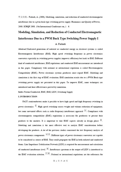
外文出处:Farhadi, A. (2008). Modeling, simulation, and reduction of conducted electromagnetic interference due to a pwm buck type switching power supply. Harmonics and Quality of Power, 2008. ICHQP 2008. 13th International Conference on, 1 - 6.Modeling, Simulation, and Reduction of Conducted Electromagnetic Interference Due to a PWM Buck Type Switching Power Supply IA. FarhadiAbstract:Undesired generation of radiated or conducted energy in electrical systems is called Electromagnetic Interference (EMI). High speed switching frequency in power electronics converters especially in switching power supplies improves efficiency but leads to EMI. Different kind of conducted interference, EMI regulations and conducted EMI measurement are introduced in this paper. Compliancy with national or international regulation is called Electromagnetic Compatibility (EMC). Power electronic systems producers must regard EMC. Modeling and simulation is the first step of EMC evaluation. EMI simulation results due to a PWM Buck type switching power supply are presented in this paper. To improve EMC, some techniques are introduced and their effectiveness proved by simulation.Index Terms:Conducted, EMC, EMI, LISN, Switching SupplyI. INTRODUCTIONFAST semiconductors make it possible to have high speed and high frequency switching in power electronics []1. High speed switching causes weight and volume reduction of equipment, but some unwanted effects such as radio frequency interference appeared []2. Compliance with electromagnetic compatibility (EMC) regulations is necessary for producers to present their products to the markets. It is important to take EMC aspects already in design phase []3. Modeling and simulation is the most effective tool to analyze EMC consideration before developing the products. A lot of the previous studies concerned the low frequency analysis of power electronics components []4[]5. Different types of power electronics converters are capable to be considered as source of EMI. They could propagate the EMI in both radiated and conducted forms. Line Impedance Stabilization Network (LISN) is required for measurement and calculation of conducted interference level []6. Interference spectrum at the output of LISN is introduced as the EMC evaluation criterion []7[]8. National or international regulations are the references forthe evaluation of equipment in point of view of EMC []7[]8.II. SOURCE, PATH AND VICTIM OF EMIUndesired voltage or current is called interference and their cause is called interference source. In this paper a high-speed switching power supply is the source of interference.Interference propagated by radiation in area around of an interference source or by conduction through common cabling or wiring connections. In this study conducted emission is considered only. Equipment such as computers, receivers, amplifiers, industrial controllers, etc that are exposed to interference corruption are called victims. The common connections of elements, source lines and cabling provide paths for conducted noise or interference. Electromagnetic conducted interference has two components as differential mode and common mode []9.A. Differential mode conducted interferenceThis mode is related to the noise that is imposed between different lines of a test circuit by a noise source. Related current path is shown in Fig. 1 []9. The interference source, path impedances, differential mode current and load impedance are also shown in Fig. 1.B. Common mode conducted interferenceCommon mode noise or interference could appear and impose between the lines, cables or connections and common ground. Any leakage current between load and common ground couldbe modeled by interference voltage source.Fig. 2 demonstrates the common mode interference source, common mode currents Iandcm1 and the related current paths[]9.The power electronics converters perform as noise source Icm2between lines of the supply network. In this study differential mode of conducted interference is particularly important and discussion will be continued considering this mode only.III. ELECTROMAGNETIC COMPATIBILITY REGULATIONS Application of electrical equipment especially static power electronic converters in different equipment is increasing more and more. As mentioned before, power electronics converters are considered as an important source of electromagnetic interference and have corrupting effects on the electric networks []2. High level of pollution resulting from various disturbances reduces the quality of power in electric networks. On the other side some residential, commercial and especially medical consumers are so sensitive to power system disturbances including voltage and frequency variations. The best solution to reduce corruption and improve power quality is complying national or international EMC regulations. CISPR, IEC, FCC and VDE are among the most famous organizations from Europe, USA and Germany who are responsible for determining and publishing the most important EMC regulations. IEC and VDE requirement and limitations on conducted emission are shown in Fig. 3 and Fig. 4 []7[]9.For different groups of consumers different classes of regulations could be complied. Class Afor common consumers and class B with more hard limitations for special consumers are separated in Fig. 3 and Fig. 4. Frequency range of limitation is different for IEC and VDE that are 150 kHz up to 30 MHz and 10 kHz up to 30 MHz respectively. Compliance of regulations is evaluated by comparison of measured or calculated conducted interference level in the mentioned frequency range with the stated requirements in regulations. In united European community compliance of regulation is mandatory and products must have certified label to show covering of requirements []8.IV. ELECTROMAGNETIC CONDUCTED INTERFERENCE MEASUREMENTA. Line Impedance Stabilization Network (LISN)1-Providing a low impedance path to transfer power from source to power electronics converter and load.2-Providing a low impedance path from interference source, here power electronics converter, to measurement port.Variation of LISN impedance versus frequency with the mentioned topology is presented inFig. 7. LISN has stabilized impedance in the range of conducted EMI measurement []7.Variation of level of signal at the output of LISN versus frequency is the spectrum of interference. The electromagnetic compatibility of a system can be evaluated by comparison of its interference spectrum with the standard limitations. The level of signal at the output of LISN in frequency range 10 kHz up to 30 MHz or 150 kHz up to 30 MHz is criterion of compatibility and should be under the standard limitations. In practical situations, the LISN output is connected to a spectrum analyzer and interference measurement is carried out. But for modeling and simulation purposes, the LISN output spectrum is calculated using appropriate software.基于压降型PWM开关电源的建模、仿真和减少传导性电磁干扰摘要:电子设备之中杂乱的辐射或者能量叫做电磁干扰(EMI)。

生产自动化毕业论文中英文资料外文翻译文献随着科技的不断进步和人们对效率的追求,生产自动化已经成为现代工业的重要组成部份。
生产自动化通过引入先进的机械和电子设备,以及自动化控制系统,实现了生产过程的自动化和智能化。
本文将介绍一些关于生产自动化的研究和应用的外文翻译文献。
1. 文献一:《生产自动化的发展与趋势》这篇文献介绍了生产自动化的发展历程和未来的趋势。
文章指出,生产自动化的发展可以追溯到20世纪初,随着电子技术和计算机技术的不断进步,生产自动化得到了快速发展。
未来,生产自动化将更加注重智能化和柔性化,以适应不断变化的市场需求。
2. 文献二:《生产自动化在汽车创造业中的应用》这篇文献探讨了生产自动化在汽车创造业中的应用。
文章指出,汽车创造业是生产自动化的典型应用领域之一。
通过引入机器人和自动化生产线,汽车创造商可以大大提高生产效率和产品质量。
此外,生产自动化还可以减少人力成本和人为错误。
3. 文献三:《生产自动化对工作环境和员工的影响》这篇文献研究了生产自动化对工作环境和员工的影响。
文章指出,尽管生产自动化可以提高生产效率,但它也带来了一些负面影响。
例如,自动化设备的噪音和振动可能对员工的健康造成影响。
此外,自动化还可能导致一些工人失去工作机会。
因此,为了最大限度地发挥生产自动化的优势,必须采取适当的安全措施和培训计划。
4. 文献四:《生产自动化在食品加工行业中的应用》这篇文献讨论了生产自动化在食品加工行业中的应用。
文章指出,食品加工是一个复杂而繁琐的过程,生产自动化可以大大提高生产效率和产品质量。
通过引入自动化设备和控制系统,食品加工商可以减少人为错误和污染风险。
此外,生产自动化还可以实现对食品生产过程的精确控制和监测。
5. 文献五:《生产自动化在医药创造业中的应用》这篇文献探讨了生产自动化在医药创造业中的应用。
文章指出,医药创造是一个高度精细和复杂的过程,生产自动化可以提高生产效率和产品质量的同时,确保药品的安全和一致性。
景德镇陶瓷学院毕业设计(论文)有关外文翻译院系:机械电子工程学院专业:自动化姓名:肖骞学号: 201010320116指导教师:万军完成时间: 2014.5.8说明1、将与课题有关的专业外文翻译成中文是毕业设计(论文)中的一个不可缺少的环节。
此环节是培养学生阅读专业外文和检验学生专业外文阅读能力的一个重要环节。
通过此环节进一步提高学生阅读专业外文的能力以及使用外文资料为毕业设计服务,并为今后科研工作打下扎实的基础。
2、要求学生查阅与课题相关的外文文献3篇以上作为课题参考文献,并将其中1篇(不少于3000字)的外文翻译成中文。
中文的排版按后面格式进行填写。
外文内容是否与课题有关由指导教师把关,外文原文附在后面。
3、指导教师应将此外文翻译格式文件电子版拷给所指导的学生,统一按照此排版格式进行填写,完成后打印出来。
4、请将封面、译文与外文原文装订成册。
5、此环节在开题后毕业设计完成前完成。
6、指导教师应从查阅的外文文献与课题紧密相关性、翻译的准确性、是否通顺以及格式是否规范等方面去进行评价。
指导教师评语:签名:年月日TMS320LF2407, TMS320LF2406, TMS320LF2402TMS320LC2406, TMS320LC2404, MS320LC2402DSP CONTROLLERSThe TMS320LF240x and TMS320LC240x devices, new members of the ‘24x family of digital signal processor (DSP) controllers, are part of the C2000 platform of fixed-point DSPs. The ‘240x devices offer the enhanced TMS320 architectural design of the ‘C2xx core CPU for low-cost, low-power, high-performance processing capabilities. Several advanced peripherals, optimized for digital motor and motion control applications, have been integrated to provide a true single chip DSP controller. While code-compatible with the existing ‘24x DSP controller devices, the ‘240x offers increased processing performance (30 MIPS) and a higher level of peripheral integration. See the TMS320x240x device summary section for device-specific features.The ‘240x family offers an array of memory sizes and different peripherals tailored to meet the specific price/performance points required by various applications. Flash-based devices of up to 32K words offer a reprogrammable solution useful for:◆Applications requiring field programmability upgrades.◆Development and initial prototyping of applications that migrate toROM-based devices.Flash devices and corresponding ROM devices are fully pin-to-pin compatible. Note that flash-based devices contain a 256-word boot ROM to facilitate in-circuit programming.All ‘240x devices offer at least one event manager module which has been optimized for digital motor control and power conversion applications. Capabilities of this module include centered- and/or edge-aligned PWM generation, programmable deadband to prevent shoot-through faults, and synchronized analog-to-digital conversion. Devices with dual event managers enable multiple motor and/or convertercontrol with a single ‗240x DSP controller.The high performance, 10-bit analog-to-digital converter (ADC) has a minimum conversion time of 500 ns and offers up to 16 channels of analog input. The auto sequencing capability of the ADC allows a maximum of 16 conversions to take place in a single conversion session without any CPU overhead.A serial communications interface (SCI) is integrated on all devices to provide asynchronous communication to other devices in the system. For systems requiring additional communication interfaces; the ‘2407, ‘2406, and ‘2404 offer a 16-bit synchronous serial peripheral interface (SPI). The ‘2407 and ‘2406 offer a controller area network (CAN) communications module that meets 2.0B specifications. To maximize device flexibility, functional pins are also configurable as general purpose inputs/outputs (GPIO).To streamline development time, JTAG-compliant scan-based emulation has been integrated into all devices. This provides non-intrusive real-time capabilities required to debug digital control systems. A complete suite of code generation tools from C compilers to the industry-standard Code Composerdebugger supports this family. Numerous third party developers not only offer device-level development tools, but also system-level design and development support.PERIPHERALSThe integrated peripherals of the TMS320x240x are described in the following subsections:●Two event-manager modules (EV A, EVB)●Enhanced analog-to-digital converter (ADC) module●Controller area network (CAN) module●Serial communications interface (SCI) module●Serial peripheral interface (SPI) module●PLL-based clock module●Digital I/O and shared pin functions●External memory interfaces (‘LF2407 only)Watchdog (WD) timer moduleEvent manager modules (EV A, EVB)The event-manager modules include general-purpose (GP) timers, full-compare/PWM units, capture units, and quadrature-encoder pulse (QEP) circuits. EV A‘s and EVB‘s timers, compare units, and capture units function identically. However, timer/unit names differ for EV A and EVB. Table 1 shows the module and signal names used. Table 1 shows the features and functionality available for the event-manager modules and highlights EV A nomenclature.Event managers A and B have identical peripheral register sets with EV A starting at 7400h and EVB starting at 7500h. The paragraphs in this section describe the function of GP timers, compare units, capture units, and QEPs using EV A nomenclature. These paragraphs are applicable to EVB with regard to function—however, module/signal names would differ.Table 1. Module and Signal Names for EV A and EVBEVENT MANAGER MODULESEV AMODULESIGNALEVBMODULESIGNALGP Timers Timer 1Timer 2T1PWM/T1CMPT2PWM/T2CMPTimer 3Timer 4T3PWM/T3CMPT4PWM/T4CMPCompare Units Compare 1Compare 2Compare 3PWM1/2PWM3/4PWM5/6Compare 4Compare 5Compare 6PWM7/8PWM9/10PWM11/12Capture Units Capture 1Capture 2Capture 3CAP1CAP2CAP3Capture 4Capture 5Capture 6CAP4CAP5CAP6QEP QEP1QEP2QEP1QEP2QEP3QEP4QEP3QEP4External Inputs DirectionExternalClockTDIRATCLKINADirectionExternal ClockTDIRBTCLKINBGeneral-purpose (GP) timersThere are two GP timers: The GP timer x (x = 1 or 2 for EV A; x = 3 or 4 for EVB) includes:● A 16-bit timer, up-/down-counter, TxCNT, for reads or writes● A 16-bit timer-compare register, TxCMPR (double-buffered with shadowregister), for reads or writes● A 16-bit timer-period register, TxPR (double-buffered with shadowregister), for reads or writes● A 16-bit timer-control register,TxCON, for reads or writes●Selectable internal or external input clocks● A programmable prescaler for internal or external clock inputs●Control and interrupt logic, for four maskable interrupts: underflow,overflow, timer compare, and period interrupts● A selectable direction input pin (TDIR) (to count up or down whendirectional up-/down-count mode is selected)The GP timers can be operated independently or synchronized with each other. The compare register associated with each GP timer can be used for compare function and PWM-waveform generation. There are three continuous modes of operations for each GP timer in up- or up/down-counting operations. Internal or external input clocks with programmable prescaler are used for each GP timer. GP timers also provide the time base for the other event-manager submodules: GP timer 1 for all the compares and PWM circuits, GP timer 2/1 for the capture units and the quadrature-pulse counting operations. Double-buffering of the period and compare registers allows programmable change of the timer (PWM) period and the compare/PWM pulse width as needed.Full-compare unitsThere are three full-compare units on each event manager. These compare units use GP timer1 as the time base and generate six outputs for compare and PWM-waveform generation using programmable deadband circuit. The state of each of the six outputs is configured independently. The compare registers of the compare units are double-buffered, allowing programmable change of the compare/PWM pulse widths as needed.Programmable deadband generatorThe deadband generator circuit includes three 8-bit counters and an 8-bit compare register. Desired deadband values (from 0 to 24 µs) can be programmed into the compare register for the outputs of the three compare units. The deadband generation can be enabled/disabled for each compare unit output individually. The deadband-generator circuit produces two outputs (with or without deadband zone) for each compare unit output signal. The output states of the deadband generator are configurable and changeable as needed by way of the double-buffered ACTR register.PWM waveform generationUp to eight PWM waveforms (outputs) can be generated simultaneously by each event manager: three independent pairs (six outputs) by the three full-compare units with programmable deadbands, and two independent PWMs by the GP-timer compares.PWM characteristicsCharacteristics of the PWMs are as follows:●16-bit registers●Programmable deadband for the PWM output pairs, from 0 to 24 µs●Minimum deadband width of 50 ns●Change of the PWM carrier frequency for PWM frequency wobbling asneeded●Change of the PWM pulse widths within and after each PWM period asneeded●External-maskable power and drive-protection interrupts●Pulse-pattern-generator circuit, for programmable generation of asymmetric,symmetric, and four-space vector PWM waveforms●Minimized CPU overhead using auto-reload of the compare and periodregistersCapture unitThe capture unit provides a logging function for different events or transitions. The values of the GP timer 2 counter are captured and stored in the two-level-deep FIFO stacks when selected transitions are detected on capture input pins, CAPx (x = 1, 2, or 3 for EV A; and x = 4, 5, or 6 for EVB). The capture unit consists of three capture circuits.Capture units include the following features:●One 16-bit capture control register, CAPCON (R/W)●One 16-bit capture FIFO status register, CAPFIFO (eight MSBs areread-only, eight LSBs are write-only)●Selection of GP timer 2 as the time base●Three 16-bit 2-level-deep FIFO stacks, one for each capture unit●Three Schmitt-triggered capture input pins (CAP1, CAP2, and CAP3)—oneinput pin per capture unit. [All inputs are synchronized with the device (CPU)clock. In order for a transition to be captured, the input must hold at itscurrent level to meet two rising edges of the device clock. The input pinsCAP1 and CAP2 can also be used as QEP inputs to the QEP circuit.]●User-specified transition (rising edge, falling edge, or both edges) detection●Three maskable interrupt flags, one for each capture unitEnhanced analog-to-digital converter (ADC) moduleA simplified functional block diagram of the ADC module is shown in Figure 1. The ADC module consists of a 10-bit ADC with a built-in sample-and-hold (S/H) circuit. Functions of the ADC module include:●10-bit ADC core with built-in S/H●Fast conversion time (S/H + Conversion) of 500 ns●16-channel, muxed inputs●Autosequencing capability provides up to 16 ―autoconversions‖ in a singlesession. Each conversion can be programmed to select any 1 of 16 inputchannels●Sequencer can be operated as two independent 8-state sequencers or as onelarge 16-state sequencer (i.e., two cascaded 8-state sequencers)●Sixteen result registers (individually addressable) to store conversion values●Multiple triggers as sources for the start-of-conversion (SOC) sequence✧S/W – software immediate start✧EV A – Event manager A (multiple event sources within EV A)✧EVB – Event manager B (multiple event sources within EVB)✧Ext – External pin (ADCSOC)●Flexible interrupt control allows interrupt request on every end of sequence(EOS) or every other EOS●Sequencer can operate in ―start/stop‖ mode, allowing multiple―time-sequenced triggers‖ to synchronize conversions●EV A and EVB triggers can operate independently in dual-sequencer mode●Sample-and-hold (S/H) acquisition time window has separate prescalecontrol●Built-in calibration mode●Built-in self-test modeThe ADC module in the ‘240x has been enhanced to provide flexible interface to event managers A and B. The ADC interface is built around a fast, 10-bit ADC module with total conversion time of 500 ns (S/H + conversion). The ADC module has 16 channels, configurable as two independent 8-channel modules to service event managers A and B. The two independent 8-channel modules can be cascaded to form a 16-channel module. Figure 2 shows the block diagram of the ‘240x ADC module.The two 8-channel modules have the capability to autosequence a series of conversions, each module has the choice of selecting any one of the respective eight channels available through an analog mux. In the cascaded mode, the autosequencer functions as a single 16-channel sequencer. On each sequencer, once the conversion is complete, the selected channel value is stored in its respective RESULT register. Autosequencing allows the system to convert the same channel multiple times, allowing the user to perform oversampling algorithms. This gives increased resolution over traditional single-sampled conversion results.FromTMS320LF2407, TMS320LF2406, TMS320LF2402TMS320LC2406, TMS320LC2404, MS320LC2402数字信号处理控制器TMS320LF240x和TMS320LC240x系列芯片作为’24x系列DSP控制器的新成员,是C2000平台下的一种定点DSP芯片。

毕业设计/论文外文文献翻译系别自动化系专业班级机械电子工程0603班姓名评分指导教师2010 年4月29日毕业设计/论文外文文献翻译要求:1.外文文献翻译的内容应与毕业设计/论文课题相关。
2.外文文献翻译的字数:非英语专业学生应完成与毕业设计/论文课题内容相关的不少于2000汉字的外文文献翻译任务(其中,汉语言文学专业、艺术类专业不作要求),英语专业学生应完成不少于2000汉字的二外文献翻译任务。
格式按《华中科技大学武昌分校本科毕业设计/论文撰写规范》的要求撰写。
3.外文文献翻译附于开题报告之后:第一部分为译文,第二部分为外文文献原文,译文与原文均需单独编制页码(底端居中)并注明出处。
本附件为封面,封面上不得出现页码。
4.外文文献翻译原文由指导教师指定,同一指导教师指导的学生不得选用相同的外文原文。
驱动桥设计随着汽车对安全、节能、环保的不断重视,汽车后桥作为整车的一个关键部件,其产品的质量对整车的安全使用及整车性能的影响是非常大的,因而对汽车后桥进行有效的优化设计计算是非常必要的。
驱动桥处于动力传动系的末端,其基本功能是增大由传动轴或变速器传来的转矩,并将动力合理地分配给左、右驱动轮,另外还承受作用于路面和车架或车身之间的垂直力力和横向力。
驱动桥一般由主减速器、差速器、车轮传动装置和驱动桥壳等组成。
驱动桥作为汽车四大总成之一,它的性能的好坏直接影响整车性能,而对于载重汽车显得尤为重要。
驱动桥设计应当满足如下基本要求:1、符合现代汽车设计的一般理论。
2、外形尺寸要小,保证有必要的离地间隙。
3、合适的主减速比,以保证汽车的动力性和燃料经济性。
4、在各种转速和载荷下具有高的传动效率。
5、在保证足够的强度、刚度条件下,力求质量小,结构简单,加工工艺性好,制造容易,拆装,调整方便。
6、与悬架导向机构运动协调,对于转向驱动桥,还应与转向机构运动协调。
智能电子技术在汽车上得以推广使得汽车在安全行驶和其它功能更上一层楼。
编号:桂林电子科技大学信息科技学院毕业设计(论文)外文翻译(译文)系别:电子工程系专业:电子信息工程学生姓名:韦骏学号:0852100329指导教师单位:桂林电子科技大学信息科技学院姓名:梁勇职称:讲师2012 年6 月5 日设计与实现基于Modbus 协议的嵌入式Linux 系统摘要:随着嵌入式计算机技术的飞速发展,新一代工业自动化数据采集和监测系统,采用核心的高性能嵌入式微处理器的,该系统很好地适应应用程序。
它符合消费等的严格要求的功能,如可靠性,成本,尺寸和功耗等。
在工业自动化应用系统,Modbus 通信协议的工业标准,广泛应用于大规模的工业设备系统,包括DCS,可编程控制器,RTU 及智能仪表等。
为了达到嵌入式数据监测的工业自动化应用软件的需求,本文设计了嵌入式数据采集监测平台下基于Modbus 协议的Linux 环境采集系统。
串行端口的Modbus 协议是实现主/从式,其中包括两种通信模式:ASCII 和RTU。
因此,各种药膏协议的设备能够满足串行的Modbus通信。
在Modbus 协议的嵌入式平台实现稳定和可靠。
它在嵌入式数据监测自动化应用系统的新收购的前景良好。
关键词:嵌入式系统,嵌入式Linux,Modbus 协议,数据采集,监测和控制。
1、绪论Modbus 是一种通讯协议,是一种由莫迪康公司推广。
它广泛应用于工业自动化,已成为实际的工业标准。
该控制装置或不同厂家的测量仪器可以链接到一个行业监控网络使用Modbus 协议。
Modbus 通信协议可以作为大量的工业设备的通讯标准,包括PLC,DCS 系统,RTU 的,聪明的智能仪表。
随着嵌入式计算机技术的飞速发展,嵌入式数据采集监测系统,使用了高性能的嵌入式微处理器为核心,是一个重要的发展方向。
在环境鉴于嵌入式Linux 的嵌入式工业自动化应用的数据,一个Modbus 主协议下的采集监测系统的设计和实现了这个文件。
因此,通信设备,各种药膏协议能够满足串行的Modbus。
外文资料翻译Power System AutomationPower system integration is the act of communication data to, or among IED s in the I&C system and remote users. Substation integration refers to combining data from the IED′s local to a substation so that there is a single point of contact in the substation for all of the I&C data. Poletop devices often communicate to the substation via wireless or fiber connections. Remote and local substation and feeder control is passed through the substation controller acting as a single point of contact. Some systems bypass the substation controller by using direct connections to the poletop devices, such as RTU s, protective relays, and controllers.Power system automation is the act of automatically controlling the power system via I&C devices. Substation automation refers to using IED data, control and automation capabilities within the substation, and control commands from remote users to control power system devices. Since true substation automation relies on substation integration, the terms are often used interchangeably.Power system automation includes processes associated with generation and delivery of power. A subset of the process deal with delivery of power at transmission and distribution levels, which is power delivery automation. Together, monitoring and control of power delivery system in the substation and on the poletop reduce the occurrence of outages and shorten the duration of outages that do occur. The IED′s, communications protocols, and communications methods described in previous sections, work together as a system to perform power system automation.Though each utility is unique, most consider power delivery automation of transmission and distribution substation and feeders to include : Supervisory Control and Data Acquisition(SCADA)-operatorsupervision and control;Distribution Automation-fault location, auto-isolation, auto-sectionalizing, and auto-restoration;Substation Automation-breaker failure, reclosing, battery monitoring, dead substation transfer, and substation load transfer;Energy Management System (EMS)-load flow, VAR and voltage monitoring and control, generation control, transformer and feeder load balancing;Fault analysis and device maintenance.System without automated control still have the advantages of remote monitoring and operator control of power system devices, which includes: Remote monitoring and control of circuit breakers and automated switches;Remote monitoring of non-automated switches and fuses;Remote monitoring and control of capacitor banks;Remote monitoring and voltage control;Remote power quality monitoring and control.IED s described in the overview are used to perform power system integration and automation. Most designs require that the one IED act as the substation controller and perform data acquisition and control of the other IED s. The substation controllers is often called upon to support system automation tasks as well. The communications industry uses the term client/server for a device that acts as a master, or client, retrieving data from some devices and then acts as a slaver, a server, sending this data to other devices. The client/server collecting and concentrating dynamically. A data concentrator creates a substation databases by collecting and concentrating dynamic data from several devices. In this fashion, essential subsets of data from each IED are forwarded to a master through one data transfer. The concentrator databases is used to pass data between IED s that are not directly connected.A substation archive client/server collects and archives data from several devices. The archive data is retrieved when it is convenient for the userto do so.The age of the IED s now in substations varies widely. Many of these IED s are still useful but lack the most recent protocols. A communications processor that can communicate with each IED via a unique baud rate and protocol extends the time that each IED is useful. Using a communications processor for substation integration also easily accommodates future IED s. It is rare for all existing IED s to be discarded during a substation integration upgrade project.The benefits of monitoring, remote control, and automation of power delivery include improved employee and public safety, and deferment of the cost of purchasing new equipment. Also, reduced operation and maintenance costs are realized through improved use of existing facilities and optimized performance of the power system through reduced losses associated with outages and improved voltage profile. Collection of information can result in better planning and system design, and increased customer satisfaction will result from improved responsiveness, service reliability, and power quality.Power system automation includes a variety of equipment. The principal items are listed and briefly described below.Instrument transformers are used to sense power system current and voltage. They are physically connected to power system apparatus and convert the actual power system signals, which includes high voltage and current magnitudes, down to lower signal levels.Transducers convert the analog output of an instrument transformer from one magnitude to another or from one value type to another, such as from an ac current to dc voltage.As the name implies, a remote terminal device, RTU, is an IED that can be installed in a remote location, and acts as a termination point for filed contacts. A dedicated pair of copper conductors are used to sense every contract and transducer value. These conductors originated at the power system device, are installed in trenches or overhead cable trays, and are thenterminated on panels within the RTU. The RTU can transfer collected data to other devices and receive data and control commands from other device through a serial port. User programmable RTUs are referred to as “smart RTUs.”A communication switch is a device that switches between several serial ports when it is told to do so. The remote user initiates communications with the port switch via a connection to the substation , typically a leased line or dial-up telephone connection. Once connected, the user can route their communication through the port switch to one of the connected substation IEDs. The port switch merely “passes through” the IED communication.A meter is an IED that is used to create accurate measurement of power system current, voltage, and power values. Metering values such as demand and peak are saved within the meter to create historical information about the activity of the power system.A digital fault recorder ,is an IED that records information about power system disturbances. It is capable of storing data in digital format when triggered by conditions detected on the power system. Harmonics, frequency, and voltage are examples of data captured by DFRs.Load tap changer are devices used to change the tap position on transformers. These devices work automatically or can be controlled via another local IED or form a remote operator or process.Recloser controllers remotely control the operation of automated reclosers and switches. These devices monitor and store power system conditions and determine when to perform control actions. They also accept commands form a remote operator or process.电力系统自动化电力系统集成是在I&C系统中的IED和远程用户之间进行数据通信的操作。
中文2570字外文文献翻译院、部:电气与信息工程学院学生姓名:指导教师:职称讲师专业:自动化班级: 09级01班完成时间: 2013.06.06出处:Computing, Communication, Control, and Management, 2008. CCCM'08. ISECS International Colloquium on. IEEE, 2008, 1: 538-541Component-based Safety Computer of Railway SignalInterlocking System1 IntroductionSignal Interlocking System is the critical equipment which can guarantee traffic safety and enhance operational efficiency in railway transportation. For a long time, the core control computer adopts in interlocking system is the special customized high-grade safety computer, for example, the SIMIS of Siemens, the EI32 of Nippon Signal, and so on. Along with the rapid development of electronic technology, the customized safety computer is facing severe challenges, for instance, the high development costs, poor usability, weak expansibility and slow technology update. To overcome the flaws of the high-grade special customized computer, the U.S. Department of Defense has put forward the concept:we should adopt commercial standards to replace military norms and standards for meeting consumers’demand [1]. In the meantime, there are several explorations and practices about adopting open system architecture in avionics. The United Stated and Europe have do much research about utilizing cost-effective fault-tolerant computer to replace the dedicated computer in aerospace and other safety-critical fields. In recent years, it is gradually becoming a new trend that the utilization of standardized components in aerospace, industry, transportation and other safety-critical fields.2 Railways signal interlocking system2.1 Functions of signal interlocking systemThe basic function of signal interlocking system is to protect train safety by controlling signal equipments, such as switch points, signals and track units in a station, and it handles routes via a certain interlocking regulation.Since the birth of the railway transportation, signal interlocking system has gone through manual signal, mechanical signal, relay-based interlocking, and the modern computer-based Interlocking System.2.2 Architecture of signal interlocking systemGenerally, the Interlocking System has a hierarchical structure. According to the function of equipments, the system can be divided to the function of equipments; the system can be divided into three layers as shown in figure1.Man-Machine Interface layerInterlocking safety layerImplementation layerOutdoorequiptmentsFigure 1 Architecture of Signal Interlocking System3 Component-based safety computer design3.1 Design strategyThe design concept of component-based safety critical computer is different from that of special customized computer. Our design strategy of SIC is on a base of fault-tolerance and system integration. We separate the SIC into three layers, the standardized component unit layer, safety software layer and the system layer. Different safety functions are allocated for each layer, and the final integration of the three layers ensures the predefined safety integrity level of the whole SIC. The three layers can be described as follows:(1) Component unit layer includes four independent standardized CPU modules. A hardware “SAFETY AND” logic is implemented in this year.(2) Safety software layer mainly utilizes fail-safe strategy and fault-tolerant management. The interlocking safety computing of the whole system adopts two outputs from different CPU, it can mostly ensure the diversity of software to hold with design errors of signal version and remove hidden risks.(3) System layer aims to improve reliability, availability and maintainability by means of redundancy.3.2 Design of hardware fault-tolerant structureAs shown in figure 2, the SIC of four independent component units (C11, C12, C21, C22). The fault-tolerant architecture adopts dual 2 vote 2 (2v2×2) structure, and a kind of high-performance standardized module has been selected as computing unit which adopts Intel X Scale kernel, 533 MHZ.The operation of SIC is based on a dual two-layer data buses. The high bus adopts thestandard Ethernet and TCP/IP communication protocol, and the low bus is Controller Area Network (CAN). C11、C12 and C21、C22 respectively make up of two safety computing components IC1 and IC2, which are of 2v2 structure. And each component has an external dynamic circuit watchdog that is set for computing supervision and switching.Diagnosis terminal C12C21C22&&Watchdog driverFail-safe switch Input modle Output Modle InterfaceConsole C11High bus(Ether NET)Low bus (CAN)Figure 2 Hardware structure of SIC3.3 Standardized component unitAfter component module is made certain, according to the safety-critical requirements of railway signal interlocking system, we have to do a secondary development on the module. The design includes power supply, interfaces and other embedded circuits.The fault-tolerant processing, synchronized computing, and fault diagnosis of SIC mostly depend on the safety software. Here the safety software design method is differing from that of the special computer too. For dedicated computer, the software is often specially designed based on the bare hardware. As restricted by computing ability and application object, a special scheduling program is commonly designed as safety software for the computer, and not a universal operating system. The fault-tolerant processing and fault diagnosis of the dedicated computer are tightly hardware-coupled. However, the safety software for SIC is exoteric and loosely hardware-coupled, and it is based on a standard Linux OS.The safety software is vital element of secondary development. It includes Linux OS adjustment, fail-safe process, fault-tolerance management, and safety interlocking logic. The hierarchy relations between them are shown in Figure 4.Safety Interlock LogicFail-safe processFault-tolerance managementLinux OS adjustmentFigure 4 Safety software hierarchy of SIC3.4 Fault-tolerant model and safety computation3.4.1 Fault-tolerant modelThe Fault-tolerant computation of SIC is of a multilevel model:SIC=F1002D(F2002(S c11,S c12),F2002(S c21,S c22))Firstly, basic computing unit Ci1 adopts one algorithm to complete the S Ci1, and Ci2 finishes the S Ci2via a different algorithm, secondly 2 out of 2 (2oo2) safety computing component of SIC executes 2oo2 calculation and gets F SICi from the calculation results of S Ci1 S Ci2, and thirdly, according the states of watchdog and switch unit block, the result of SIC is gotten via a 1 out of 2 with diagnostics (1oo2D) calculation, which is based on F SIC1 and F SIC2.The flow of calculations is as follows:(1) S ci1=F ci1 (D net1,D net2,D di,D fss)(2) S ci2=F ci2 (D net1,D net2,D di,D fss)(3) F SICi=F2oo2 (S ci1, S ci2 ),(i=1,2)(4) SIC_OutPut=F1oo2D (F SIC1, F SIC2)3.4.2 Safety computationAs interlocking system consists of a fixed set of task, the computational model of SIC is task-based. In general, applications may conform to a time-triggered, event-triggered or mixed computational model. Here the time-triggered mode is selected, tasks are executed cyclically. The consistency of computing states between the two units is the foundation of SIC for ensuring safety and credibility. As SIC works under a loosely coupled mode, it is different from that of dedicated hardware-coupled computer. So a specialized synchronization algorithm is necessary for SIC.SIC can be considered as a multiprocessor distributed system, and its computational model is essentially based on data comparing via high bus communication. First, an analytical approach is used to confirm the worst-case response time of each task. To guarantee the deadline of tasks that communicate across the network, the access time and delay of communication medium is set to a fixed possible value. Moreover, the computational model must meets the real time requirements of railway interlocking system, within the system computing cycle, we set many check points P i(i=1,2,... n) , which are small enough for synchronization, and computation result voting is executed at each point. The safetycomputation flow of SIC is shown in Figure 5.S t a r tS t a r t0τ1τ2τ1P2P0τ1τ2τ1P2P0T0TC1i Ci 21T2T1T2T…………………n+1τn+1τn Pn Pn τn τclockclockS a f e t y f u n c t i o n s T a s k s o f i n t e r l o c k i n g l o g i c i :p:c h e c k p o i n t I n i t i a l i z e S y n c h r o n i z a t i o n G u a r a n t e e S y n c h r o n o u s T i m e t r i g g e rFigure 5 Safety computational model of SIC4. Hardware safety integrity level evaluation4.1 Safety IntegrityAs an authoritative international standard for safety-related system, IEC 61508 presents a definition of safety integrity: probability of a safety-related system satisfactorily performing the required safety functions under all the stated conditions within a stated period of time. In IEC 61508, there are four levels of safety integrity are prescribe, SIL1~SIL4. The SIL1 is the lowest, and SIL4 highest.According to IEC 61508, the SIC belongs to safety-related systems in high demand or continuous mode of operation. The SIL of SIC can be evaluated via the probability of dangerous per hour. The provision of SIL about such system in IEC 61508, see table 1.Table 1-Safety Integrity levels: target failure measures for a safety function operating in high demand orcontinuous mode of operationSafety Integrity levelHigh demand or continuous mode of Operation (Probability of a dangerous Failure per hour)4 ≥10-9 to <10-83 ≥10-8 to <10-72 ≥10-7 to <10-61 ≥10-6 to <10-54.2 Reliability block diagram of SICAfter analyzing the structure and working principle of the SIC, we get the bock diagram of reliability, as figure 6.2002200220022002NET1NET2NET1NET2λ=1×10⁻⁷DC=99%Voting=1002D λ=1×10⁻⁷DC=99%Voting=1002D λ=1×10Β=2%βD =1%DC=99%Voting=1002D High busLogic subsystem Low busFigure 6 Block diagram of SIC reliability5. ConclusionsIn this paper, we proposed an available standardized component-based computer SIC. Railway signal interlocking is a fail-safe system with a required probability of less than 10-9 safety critical failures per hour. In order to meet the critical constraints, fault-tolerant architecture and safety tactics are used in SIC. Although the computational model and implementation techniques are rather complex, the philosophy of SIC provides a cheerful prospect to safety critical applications, it renders in a simpler style of hardware, furthermore, it can shorten development cycle and reduce cost. SIC has been put into practical application, and high performance of reliability and safety has been proven.模块化安全铁路信号计算机联锁系统1概述信号联锁系统是保证交通安全、提高铁路运输效率的关键设备。
南京理工大学紫金学院毕业设计(论文)外文资料翻译系:机械系专业:车辆工程专业姓名:宋磊春学号:070102234外文出处:EDU_E_CAT_VBA_FF_V5R9(用外文写)附件:1。
外文资料翻译译文;2.外文原文.附件1:外文资料翻译译文CATIA V5 的自动化CATIA V5的自动化和脚本:在NT 和Unix上:脚本允许你用宏指令以非常简单的方式计划CATIA。
CATIA 使用在MS –VBScript中(V5.x中在NT和UNIX3。
0 )的共用部分来使得在两个平台上运行相同的宏。
在NT 平台上:自动化允许CATIA像Word/Excel或者Visual Basic程序那样与其他外用分享目标。
ATIA 能使用Word/Excel对象就像Word/Excel能使用CATIA 对象。
在Unix 平台上:CATIA将来的版本将允许从Java分享它的对象。
这将提供在Unix 和NT 之间的一个完美兼容。
CATIA V5 自动化:介绍(仅限NT)自动化允许在几个进程之间的联系:CATIA V5 在NT 上:接口COM:Visual Basic 脚本(对宏来说),Visual Basic 为应用(适合前:Word/Excel ),Visual Basic。
COM(零部件目标模型)是“微软“标准于几个应用程序之间的共享对象。
Automation 是一种“微软“技术,它使用一种解释环境中的COM对象。
ActiveX 组成部分是“微软“标准于几个应用程序之间的共享对象,即使在解释环境里。
OLE(对象的链接与嵌入)意思是资料可以在一个其他应用OLE的资料里连结并且可以被编辑的方法(在适当的位置编辑).在VBScript,VBA和Visual Basic之间的差别:Visual Basic(VB)是全部的版本。
它能产生独立的计划,它也能建立ActiveX 和服务器。
它可以被编辑。
VB中提供了一个补充文件名为“在线丛书“(VB的5。
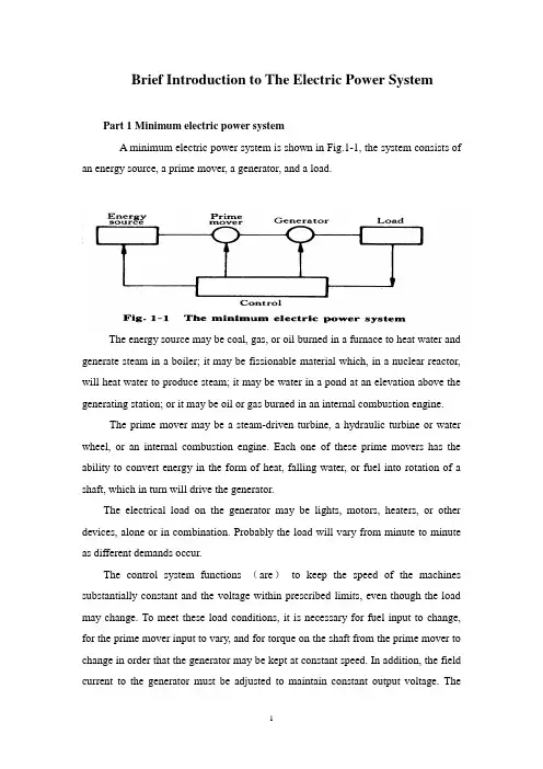
Brief Introduction to The Electric Power SystemPart 1 Minimum electric power systemA minimum electric power system is shown in Fig.1-1, the system consists of an energy source, a prime mover, a generator, and a load.The energy source may be coal, gas, or oil burned in a furnace to heat water and generate steam in a boiler; it may be fissionable material which, in a nuclear reactor, will heat water to produce steam; it may be water in a pond at an elevation above the generating station; or it may be oil or gas burned in an internal combustion engine.The prime mover may be a steam-driven turbine, a hydraulic turbine or water wheel, or an internal combustion engine. Each one of these prime movers has the ability to convert energy in the form of heat, falling water, or fuel into rotation of a shaft, which in turn will drive the generator.The electrical load on the generator may be lights, motors, heaters, or other devices, alone or in combination. Probably the load will vary from minute to minute as different demands occur.The control system functions (are)to keep the speed of the machines substantially constant and the voltage within prescribed limits, even though the load may change. To meet these load conditions, it is necessary for fuel input to change, for the prime mover input to vary, and for torque on the shaft from the prime mover to change in order that the generator may be kept at constant speed. In addition, the field current to the generator must be adjusted to maintain constant output voltage. Thecontrol system may include a man stationed in the power plant who watches a set of meters on the generator output terminals and makes the necessary adjustments manually. In a modern station, the control system is a servomechanism that senses generator-output conditions and automatically makes the necessary changes in energy input and field current to hold the electrical output within certain specifications..Part 2 More Complicated SystemsIn most situations the load is not directly connected to the generator terminals. More commonly the load is some distance from the generator, requiring a power line connecting them. It is desirable to keep the electric power supply at the load within specifications. However, the controls are near the generator, which may be in another building, perhaps several miles away.If the distance from the generator to the load is considerable, it may be desirable to install transformers at the generator and at the load end, and to transmit the power over a high-voltage line (Fig.1-2). For the same power, the higher-voltage line carries less current, has lower losses for the same wire size, and provides more stable voltage.In some cases an overhead line may be unacceptable. Instead it may be advantageous to use an underground cable. With the power systems talked above, the power supply to the load must be interrupted if, for any reason, any component of the system must be moved from service for maintenance or repair. Additional system load may require more power than the generator can supply. Another generator with its associated transformers and high-voltage line might be added.It can be shown that there are some advantages in making ties between the generators (1) and at the end of the high-voltage lines (2 and 3), as shown in Fig.1-3. This system will operate satisfactorily as long as no trouble develops or no equipmentneeds to be taken out of service.The above system may be vastly improved by the introduction of circuit breakers, which may be opened and closed as needed. Circuit breakers added to the system, Fig.1-4, permit selected piece of equipment to switch out of service without disturbing the remainder of system. With this arrangement any element of the system may be deenergized for maintenance or repair by operation of circuit breakers.Of course, if any piece of equipment is taken out of service, then the total load must be carried by the remaining equipment. Attention must be given to avoid overloads during such circumstances. If possible, outages of equipment are scheduled at times when load requirements are below normal.Fig.1-5 shows a system in which three generators and three loads are tied together by three transmission lines. No circuit breakers are shown in this diagram, although many would be required in such a system.Part 3 Typical System LayoutThe generators, lines, and other equipment which form an electric system are arranged depending on the manner in which load grows in the area and may be rearranged from time to time.However, there are certain plans into which a particular system design may be classified. Three types are illustrated: the radial system, the loop system, and the network system. All of these are shown without the necessary circuit breakers. In each of these systems, a single generator serves four loads.The radial system is shown in Fig.1-6. Here the lines form a “tree” spreading out from the generator. Opening any line results in interruption of power to one or more of the loads.The loop system is illustrated in Fig.1-7. With this arrangement all loads may be served even though one line section is removed from service. In some instances during normal operation, the loop may be open at some point, such as A. In case a line section is to be taken out, the loop is first closed at A and then the line section removed. In this manner no service interruptions occur.Fig.1-8 shows the same loads being served by a network. With this arrangement each load has two or more circuits over which it is fed.Distribution circuits are commonly designed so that they may be classified as radial or loop circuits. The high-voltage transmission lines of most power systems are arranged as network. The interconnection of major power system results in networks made up by many line sections.Part 4 Auxiliary EquipmentCircuit breakers are necessary to deenergize equipment either for normal operation or on the occurrence of short circuits. Circuit breakers must be designed to carry normal-load currents continuously, to withstand the extremely high currents that occur during faults, and to separate contacts and clear a circuit in the presence of fault. Circuit breakers are rated in terms of these duties.When a circuit breaker opens to deenergize a piece of equipment, one side of the circuit breaker usually remains energized, as it is connected to operating equipment. Since it is sometimes necessary to work on the circuit breaker itself, it is also necessary to have means by which the circuit breaker may be completely disconnected from other energized equipment. For this purpose disconnect switches are placed in series with the circuit breakers. By opening these disconnectors, thecircuit breaker may be completely deenergized, permitting work to be carried on in safety.Various instruments are necessary to monitor the operation of the electric power system. Usually each generator, each transformer bank, and each line has its own set of instruments, frequently consisting of voltmeters, ammeters, wattmeters, and varmeters.When a fault occurs on a system, conditions on the system undergo a sudden change. V oltages usually drop and currents increase. These changes are most noticeable in the immediate vicinity of fault. On-line analog computers, commonly called relays, monitor these changes of conditions, make a determination of which breaker should be opened to clear the fault, and energize the trip circuits of those appropriate breakers. With modern equipment, the relay action and breaker opening causes removal of fault within three or four cycles after its initiation.The instruments that show circuit conditions and the relays that protect the circuits are not mounted directly on the power lines but are placed on switchboards in a control house. Instrument transformers are installed on the high-voltage equipment, by means of which it is possible to pass on to the meters and relays representative samples of the conditions on the operating equipment. The primary of a potential transformer is connected directly to the high-voltage equipment. The secondary provides for the instruments and relays a voltage which is a constant fraction of voltage on the operating equipment and is in phase with it;similarly, a current transformer is connected with its primary in the high-current circuit. The secondary winding provides a current that is a known fraction of the power-equipment current and is in phase with it.Bushing potential devices and capacitor potential devices serve the same purpose as potential transformers but usually with less accuracy in regard to ratio and phase angle.中文翻译:电力系统的简介第一部分:最小电力系统一个最小电力系统如图1-1所示,系统包含动力源,原动机,发电机和负载。
自适应PID控制器基于Ziegler Nichols自整定方法的参数的PLC摘要本文介绍一种改进的PID控制器是作为一个动态的系统控制器和必要的步骤,是解释以表达对所提出的PID控制算法是更多的功能比传统的PID控制算法。
在这里齐格勒-尼科尔斯的过程中反应的方法是澄清,以候任自校正,及的优势,自我调整中有详细的解释。
之后,自适应丕三维控制器的算法,给出了使用自整定方法的初始参数。
在这丕三维,比例和积分参数是在控制的自适应算法和衍生产品的参数是一个不断发现,在齐格勒尼科尔斯基于自整定方法。
最后,完整的算法是测试在可编程逻辑控制器,和结果,这项测试是提供和解释。
PID控制器一比例积分微分控制器或PID控制器是一种常见的用于控制器在工业控制应用。
控制器的比较衡量的过程产值(元Y )与参考设定值()值。
差异或错误信号( e )是处理,然后计算控制信号为操纵的过程中的投入,使系统输出达到所期望的参考价值。
不同于简单的控制算法,PID控制器可以调整的过程中投入的基础上,历史和变化率的错误信号,这使更准确和更稳定的控制。
在这方面的文件,不同结构的PID控制器是使用。
图1结构的PID控制器图1结构的PID控制器众所周知,衍生金融工具可以计算或获得如果错误变缓慢。
由于反应衍生工具,以高频率的投入是远远高于其反应慢变信号[ 13 ] 。
因此,衍生金融工具的输出在图1是smoothened为高频率的噪音,用一阶过滤器,它使用的输出系统(y )的。
衍生工具使用错误的信号可以形成高,衍生金融工具的输出时,误差信号具有较高的高频成分。
因此,在本文件中衍生金融工具的投入使用过滤的输出系统。
在这里,过滤器smoothens信号和抑制高频率的噪音,由于过滤器的时间(TF )的常数(图2 )。
在应用,其TF应大于6月24日ts采样周期[ 6 ,16 ] 。
图2 ,稳定系统的输出响应(PLC模拟)在图1 ,积分信号是由错误乘以增益(k )和除以积分时间,和饱和度的差异除以积分时间。
附录:中英文翻译英文Simulation-based Comparisons of Tahoe, Reno, and SACK TCPKevin Fall and Sally Floyd1 IntroductionIn this paper we illustrate some of the benefits of adding selective acknowledgment (SACK) to TCP. Current implementations of TCP use an acknowledgment number field that contains a cumulative acknowledgment, indicating the TCP receiver has received all of the data up to the indicated byte. A selective acknowledgment option allows receivers to additionally report non-sequential data they have received. When coupled with a selective retransmission policy implemented in TCP senders, This work was supported by the Director, office of Energy Re-search, Scientific Computing Staff, of the U.S. Department of Energy under considerable savings can be achieved Several transport protocols have provided for selective acknowledgment (SACK) of received data. These include NETBLT [CLZ87], XTP [SDW92], RDP [HSV84] and VMTP [Che88]. The first proposals for adding SACK to TCP [BJ88, BJZ90] were later removed from the TCP RFCs (Request For Comments) [BBJ92] pending further research. The cur-rent proposal for adding SACK to TCP is given in [MMFR96]. We use simulations to show how the SACK option define in [MMFR96] can be of substantial benefits relative to TCP without SACK.Without SACK, Reno TCP has performance problems when multiple packets are dropped from one window of data. These problems result from the need to await aretransmission timer expiration before re-initiating data flow. Situations in which this problem occurs are illustrated later in this paper (for example, see Section 6.4).Not all of Reno's performance problems are a necessary consequence of the absence of SACK. To show why, we implemented a variant of the Reno algorithms in our simulator, called New-Reno. Using a suggestion from Janey Hoe [Hoe95, Hoe96], New-Reno avoids many of the retransmit timeouts of Reno without requiring SACK. Nevertheless, New-Reno does not perform as well as TCP with SACK when a large number of packets are dropped from a window of data. The purpose of our discussion of New-Reno is to clarify the fundamental limitations of the absence of SACK. In the absence of SACK, both Reno and New-Reno senders can retransmit at most one dropped packet per round-trip time, even if senders recover from multiple drops in a window of data without waiting for a retransmit timeout. This characteristic is not shared by Tahoe TCP, which is not limited to retransmitting at most one dropped packet per round-trip time. However, it is a fundamental consequence of the absence of SACK that the sender has to choose between the following strategies to recover from lost data:1retransmitting at most one dropped packet per round-trip time, or2retransmitting packets that might have already been successfully delivered.To illustrate the advantages of TCP with SACK, we show simulations with SACK TCP, using the SACK implementation in our simulator. SACK TCP is based on a conservative extension of the Reno congestion control algorithms with the addition of selective acknowledgments and selective retransmission. With SACK, a sender has a better idea of exactly which packets have been successfully delivered as compared with comparable protocols lacking SACK. Given such information, a sender can avoid unnecessary delays and retransmissions, resulting in improved throughput. We believe the addition of SACK to TCP is one of the most important changes that should be made to TCP at this time to improve its performance.In Sections 2 through 5 we describe the congestion control and packet retransmission algorithms in Tahoe, Reno, New-Reno, and SACK TCP. Section 6 shows simulations with Tahoe, Reno, New-Reno, and SACK TCP in scenariosranging from one to four packets dropped from a window of data. Section 7 shows a trace of Reno TCP taken from actual Internet traffic, showing that the performance problems of Reno without SACK are of more than theoretical interest. Finally, Section 8 discusses possible future directions for TCP with selective acknowledgments, and Section 9 gives conclusions.2 Tahoe TCPModern TCP implementations contain a number of algorithms aimed at controlling network congestion while maintaining good user throughput. Early TCP implementations followed a go-back-n.model using cumulative positive acknowledgment and requiring a retransmit timer expiration to re-send data lost during transport. These TCPs did little to minimize network congestion.The Tahoe TCP implementation added a number of new algorithms and refinements to earlier implementations. The new algorithms include Slow-Start, Congestion Avoidance, and Fast Retransmit [Jac88]. The refinements include a modification to the round-trip time estimator used to set retransmission timeout values. All modifications have been described elsewhere [Jac88, Ste94].The Fast Retransmit algorithm is of special interest in this paper because it is modified subsequent versions of TCP. With Fast Retransmit, after receiving a small number of duplicate acknowledgments for the same TCP segment (dup ACKs), the data sender infers that a packet has been lost and retransmits the packet without waiting for a retransmission timer to expire, leading to higher channel utilization and connection throughput.3 Reno TCPThe Reno TCP implementation retained the enhancements incorporated into Tahoe, but modified the Fast Retransmit operation to include Fast Recovery [Jac90]. The new algorithm prevents the communication path (“pipe”) from going empty after Fast Retransmit, thereby avoiding the need to Slow-Start to refill it after a single packet loss. Fast Recovery operates by assuming each dup ACK received represents a single packet having left the pipe. Thus, during Fast Recovery the TCP sender is ableto make intelligent estimates of the amount of outstanding data.In Reno, the sender's usable window becomes other gateways that fail to monitor the average queue size) until the number of dup ACKs reaches tcprexmtthresh, and thereafter tracks the number of duplicate ACKs. Thus, during Fast Recovery the sender “inflate” its window by the number of dup ACKs it has received, according to the observation that each dup ACK indicates some packet has been removed from the network and is now cached at the receiver. After entering Fast Recovery and retransmitting a single packet, the sender effectively waits until half a window of dup ACKs have been received, and then sends a new packet for each additional dup ACK that is received.4 New-Reno TCPWe include New-Reno TCP in this paper to show how a simple change to TCP makes it possible to avoid some of the performance problems of Reno TCP without the addition of SACK. At the same time, we use New-Reno TCP to explore the fundamental limitations of TCP performance in the absence of SACK.The New-Reno TCP in this paper includes a small change to the Reno algorithm at the sender that eliminates Reno's wait for a retransmit timer when multiple packets are lost from a window [Hoe95, CH95]. The change concerns the sender's behavior during Fast Recovery when a partial ACK is received that acknowledges some but not all of the packets that were out-standing at the start of that Fast Recovery period. In Reno, partial ACKs take TCP out of Fast Recovery by “deflating” the usable window back to the size of the congestion window. In New-Reno, partial ACKs do not take TCP out of Fast Recovery. Instead, partial ACKs received during Fast Recovery are treated as an indication that the packet immediately following the acknowledged packet in the sequence space has been lost, and should be retransmitted. Thus, when multiple packets are lost from a single window of data, New-Reno can recover without a retransmission timeout, retransmitting one lost packet per round-trip time until all of the lost packets from that window have been retransmitted. New-Reno remains in Fast Recovery until all of the data outstanding when Fast Recovery was initiated has been acknowledged.The implementations of New-Reno and SACK TCP in our simulator also use a “maxburst” parameter. In our SACK TCP implementation, the “maxburst” parameter limits to four the number of packets that can be sent in response to a single incoming ACK, even if the sender's congestion window would allow more packets to be sent. In New-Reno, the “maxburst” parameter is set to four packets outside of Fast Recovery, and to two packets during Fast Recovery, to more closely reproduce the behavior of Reno TCP during Fast Recovery. The “maxburst” parameter is really only needed for the first window of packets that are sent after leaving Fast Recovery. If the sender had been prevented by the receiver's advertised window from sending packets during Fast Recovery, then, without “maxburst” ,it is possible for the sender to send a large burst of packets upon exiting Fast Recovery. This applies to Reno and New-Reno TCP, and to a lesser extent, to SACK TCP. In Tahoe TCP the Slow-Start algorithm prevents bursts after recovering from a packet loss. The bursts of packets upon exiting Fast Recovery with New-Reno TCP are illustrated in Section 6 in the simulations with three and four packet drops. Bursts of packets upon exiting Fast Recovery with Reno TCP are illustrated in [Flo95].5 SACK TCPThe SACK option follows the format in [MMFR96]. From [MMFR96], the SACK option field contains a number of SACK blocks, where each SACK block reports a non-contiguous set of data that has been received and queued. The first block in a SACK option is required to report the data receiver's most recently received segment, and the additional SACK blocks repeat the most recently reported SACK blocks [MMFR96]. In these simulations each SACK option is assumed to have room for three SACK blocks. When the SACK option is used with the Timestamp option specified for TCP Extensions for High Performance [BBJ92], then the SACK option has room for only three SACK blocks [MMFR96]. If the SACK option were to be used with both the Timestamp option and with T/TCP (TCP Extensions for Transactions) [Bra94], the TCP option space would have room for only two SACK blocks.The 1990 “Sack” TCP implementation on our previous simulator is from StevenMcCanne and Sally Floyd, and does not conform to the formats in [MMFR96]. The new “Sack1”implementation contains major contributions from Kevin Fall, Jamshid Mahdavi, and Matt Mathis.The congestion control algorithms implemented in our SACK TCP are a conservative extension of Reno's congestion control, in that they use the same algorithms for increasing and decreasing the congestion window,The SACK TCP implementation in this paper, called “Sack1”in our simulator, is also discussed in [Flo96b, Flo96a].and make minimal changes to the other congestion con-trol algorithms. Adding SACK to TCP does not change the basic underlying congestion control algorithms. The SACK TCP implementation preserves the properties of Tahoe and Reno TCP of being robust in the presence of out-of-order packets, and uses retransmit timeouts as the recovery method of last resort. The main difference between the SACK TCP implementation and the Reno TCP implementation is in the behavior when multiple packets are dropped from one window of data.中文翻译:1介绍在这篇论文中,我们将介绍使用选择重发(sack)选项的TCP协议的益处,拥塞控制,算法一般分为两类:基于窗口的和基于位率的拥塞控制算法,基于窗口的控制算法是通过源端限制数据报的传送,并且不应答。
自动化专业英语原文和翻译Abstract:This document provides a comprehensive overview of the field of automation, including its definition, applications, and current trends. It also includes a detailed explanation of key terms and concepts related to automation. The document aims to serve as a resource for professionals and students in the field of automation, as well as anyone interested in gaining a deeper understanding of this rapidly evolving discipline.1. IntroductionAutomation is the use of technology to perform tasks with minimal human intervention. It involves the design, development, and implementation of systems that can operate autonomously or semi-autonomously. Automation has revolutionized various industries, including manufacturing, transportation, healthcare, and agriculture, by increasing efficiency, productivity, and safety.2. Definition and ScopeAutomation encompasses a wide range of technologies and processes, such as robotics, artificial intelligence, machine learning, and control systems. It involves the integration of hardware and software components to create intelligent systems capable of performing complex tasks. The scope of automation includes industrial automation, process automation, home automation, and office automation.3. Applications of Automation3.1 Manufacturing AutomationManufacturing automation involves the use of machines and robotic systems to automate production processes. It includes tasks such as assembly, packaging, material handling, and quality control. Automation in manufacturing has led to increased production rates, improved product quality, and reduced labor costs.3.2 Transportation AutomationTransportation automation aims to automate various aspects of transportation systems, including vehicles, traffic control, and logistics. It includes technologies such as autonomous vehicles, intelligent transportation systems, and automated warehouses. Automation in transportation can enhance safety, reduce congestion, and optimize resource utilization.3.3 Healthcare AutomationHealthcare automation involves the use of technology to streamline healthcare processes and improve patient care. It includes electronic medical records, telemedicine, robotic surgery, and automated drug dispensing systems. Automation in healthcare can enhance accuracy, reduce errors, and improve overall efficiency.3.4 Agriculture AutomationAgriculture automation focuses on automating agricultural processes to increase productivity and reduce labor requirements. It includes technologies such as precision farming, automated irrigation systems, and robotic harvesting. Automation in agriculture can optimize resource usage, improve crop yields, and minimize environmental impact.4. Key Terms and Concepts4.1 RoboticsRobotics is the branch of automation that deals with the design, construction, and operation of robots. Robots are programmable machines capable of carrying out tasks autonomously or under human supervision. They can be used in various industries for tasks that are dangerous, repetitive, or require high precision.4.2 Artificial Intelligence (AI)Artificial Intelligence refers to the ability of machines to mimic human intelligence and perform tasks that typically require human intelligence, such as speech recognition,decision-making, and problem-solving. AI is a key component of many automation systems, enabling machines to learn from data and adapt to changing conditions.4.3 Machine LearningMachine Learning is a subset of AI that focuses on the development of algorithms and models that allow machines to learn from data and make predictions or decisions without explicit programming. Machine learning algorithms are used in various automation applications, such as image recognition, natural language processing, and predictive maintenance.4.4 Control SystemsControl systems are used to monitor and regulate the behavior of machines and processes. They involve sensors, actuators, and feedback mechanisms to maintain desired performance and stability. Control systems are essential in automation to ensure accurate and reliable operation of automated systems.5. Current Trends in Automation5.1 Internet of Things (IoT)The Internet of Things refers to the network of interconnected devices that can communicate and exchange data. IoT enables automation by connecting physical objects to the internet, allowing remote monitoring and control. It has applications in various domains, such as smart homes, industrial automation, and healthcare.5.2 Big Data AnalyticsBig Data Analytics involves the use of advanced analytics techniques to extract insights from large and complex datasets. In automation, big data analytics can be used to optimize processes, detect anomalies, and make data-driven decisions. It enables predictive maintenance, real-time monitoring, and continuous improvement.5.3 Collaborative RobotsCollaborative robots, also known as cobots, are designed to work alongside humans in a shared workspace. They are equipped with sensors and safety features to ensure safe interaction with humans. Collaborative robots are increasingly used in manufacturing, healthcare, and other industries to enhance productivity and flexibility.Conclusion:Automation is a rapidly evolving field with significant implications for various industries and society as a whole. This document has provided an in-depth overview of automation, including its definition, applications, key terms, and current trends. It serves as a valuable resource for professionals and students in the field of automation, as well as anyone interested in understanding the fundamental concepts and advancements in this exciting discipline.。
自动化专业毕业设计(论文)外文翻译Electronic power steering systemWhat it isElectrically powered steering uses an electric motor to drive either the power steering HYPERLINK "/infobank/epc.htm" \t "_top" hydraulic pump or the steering linkage directly. The power steering function is therefore independent of engine speed, resulting in significant energy savings.How it works :Conventional power HYPERLINK "/infobank/epc.htm" \t "_top" steering systems use an engine accessory belt to drive the pump, providing pressurized fluid that operates a piston in the power steering gear or actuator to assist the driver.In electro-hydraulic steering, one electrically powered steering concept uses a high efficiencypump driven by an HYPERLINK "/infobank/epc.htm" \t "_top" electric motor. Pump speed is regulated by an electric controller to vary pump pressure and flow, providing steering efforts tailored for different driving situations. The pump can be run at low speed or shut off to provide energy savings during straight ahead driving (which is most of the time in most world markets).Direct electric steering uses an electric motor attached to the HYPERLINK "/infobank/epc.htm" \t "_top" steering rack via a gear mechanism (no pump or fluid). A variety of motor types and gear drives is possible. A microprocessor controls steering dynamics and driver effort. Inputs include vehicle speed and steering, wheel torque, angular position and turning rate.Working In Detail:A "steering sensor" is located on the input shaft where it enters the gearbox housing. The steering sensor is actually two sensors in one: a "torque sensor" that converts steering torque input and its direction into voltage signals, and a "rotation sensor" that converts the rotation speed and direction into voltage signals. An "interface" circuit that shares the same housing converts the signals from the torque sensor and rotation sensor into signals the control electronics can process. Inputs from the steering sensor are digested by a microprocessor control unit that also monitors input from the vehicle's HYPERLINK "/infobank/epc.htm" \t "_top" speed sensor. The sensor inputs are then compared to determine how much power assist is required according to a preprogrammed "force map" in the control unit's memory. The control unit then sends out the appropriate command to the " HYPERLINK "/infobank/epc.htm" \t "_top" power unit" which then supplies the electric motor with current. The motor pushes the rack to the right or left depending on which way the voltage flows (reversing the current reverses the direction the motor spins). Increasing the current to the motor increases the amount of power assist.The system has three operating modes: a "normal" control mode in which left or right power assist is provided in response to input from the steering torque and rotationsensor's inputs; a "return" control mode which is used to assist steering return after completing a turn; and a "damper" control mode that changes with vehicle speed to improve road feel and dampen kickback.If the steering wheel is turned and held in the full-lock position and steering assist reaches a maximum, the control unit reduces current to the electric motor to prevent an overload situation that might damage the motor. The control unit is also designed to protect the motor against voltage surges from a faulty HYPERLINK "/infobank/epc.htm" \t "_top" alternator or charging problem. The electronic steering control unit is capable of self-diagnosing faults by monitoring the system's inputs and outputs, and the driving current of the electric motor. If a problem occurs, the control unit turns the system off by actuating a fail-safe relay in the power unit. This eliminates all power assist, causing the system to revert back to manual steering. A dash EPS warning light is also illuminated to alert the driver. To diagnose the problem, a technician jumps the terminals on the service check connector and reads out the HYPERLINK "/infobank/epc.htm" \t "_top" trouble codes. INCLUDEPICTURE "/infobank/images/eps-18-4.gif" \* MERGEFORMATINETHYPERLINK "/infobank/images/c01e.gif" click here to see a bigger HYPERLINK "/infobank/images/c01e.gif"INCLUDEPICTURE "/infobank/images/c01e.gif" \*MERGEFORMATINETElectric power steering systems promise weight reduction, fuel savings and package flexibility, at no cost penalty.Europe's high fuel prices and smaller vehicles make a fertile testbed for electric steering, a technology that promises automakers weight savings and fuel economy gains. And in a short time, electric steering will make it to the U.S., too. "It's just just a matter of time," says AlyBadawy, director of research and development for Delphi Saginaw Steering Systems in Saginaw, Mich. "The issue was cost and that's behind us now. By 2002 here in the U.S. the cost of electric power steering will absolutely be a wash over hydraulic." Today, electric and hybrid-powered vehicles (EV), including Toyota's Prius and GM's EV-1, are the perfect domain for electric steering. But by 2010, a TRW Inc. internal study estimates that one out of every three cars produced in the world will be equipped with some form of electrically-assisted steering. The Cleveland-based supplier claims its new steering systems could improve fuel economy by up to 2 mpg, while enhancing handling. There are true bottom-line benefits as well for automakers by reducing overall costs and decreasing assembly time, since there's no need for pumps, hoses and fluids. Another claimed advantage is shortened development time. For instance, a Delphi group developed E-TUNE, a ride-and-handling software package that can be run off a laptop computer. "They can take that computer and plug it in, attach it to the controller and change all the handling parameters -- effort level, returnability, damping -- on the fly," Badawy says. "It used to take months." Delphi has one OEM customer that should start low-volume production in '99. HYPERLINK "/adlog/c/r=12640&s=790604&o=13886:14023:13888:15399:&h=c n&p=&b=14&l=&site=23&pt=&nd=&pid=&cid=&pp=100&e=&rqid=01c17-ad-e8480771F615DF093&orh=LINE&oepartner=&epartner=&ppartner=&pdom=&cpnmod ule=&count=&ra=10.15.56.33&t=2008.04.19.09.09.02/http://cm/ck/9 998-57911-18316-1?mpt=2008.04.19.09.09.02" \t "_blank" Electric steering units are normally placed in one of three positions: column-drive, pinion-drive and rack-drive. Which system will become the norm is still unclear. Short term, OEMs will choose the steering system that is easiest to integrate into an existing platform. Obviously, greater potential comes from designing the system into an all-new platform. "We have all three designs under consideration," says Dr. Herman Strecker, group vice president of steering systems division at ZF in SchwaebischGmuend, Germany. "It's up to the market and OEMs which version finally will be used and manufactured." "The large manufacturers have all grabbed hold of what they consider a core technology," explains James Handy sides, TRW vice president, electrically assisted steering in Sterling Heights, Mich. His company offers a portfolio of electric steering systems (hybrid electric, rack-, pinion-, and column-drive). TRW originally concentrated on what it still believes is the purest engineering solution for electric steering--the rack-drive system. The system is sometimes refer to as direct drive or ball/nut drive. Still, this winter TRW hedged its bet, forming a joint venture with LucasVarity. The British supplier received $50 million in exchange for its electric column-drive steering technology and as sets. Initial production of the column and pinion drive electric steering systems is expected to begin in Birmingham, England, in 2000."What we lack is the credibility in the steering market," says Brendan Conner, managing director, TRW/LucasVarity Electric Steering Ltd. "The combination with TRW provides us with a good opportunity for us to bridge that gap." LucasVarity currently has experimental systems on 11 different vehicle types, mostly European. TRW is currently supplying its EAS systems for Ford and Chrysler EVs in North America and for GM's new Opel Astra.In 1995, according to Delphi, traditional hydraulic power steering systems were on 7596 of all vehicles sold globally. That 37-million vehicle pool consumes about 10 million gallons in hydraulic fluid that could be superfluous, if electric steering really takes off. The present invention relates to an electrically powered drive mechamsm for providing powered assistance to a vehicle steering mechanism. According to one aspect of the present invention, there is provided an electrically powered driven mechanism for providing powered assistance to a vehicle steering mechanism having a manually rotatable member for operating the steering mechanism, the drive mechanism including a torque sensor operable to sense torque being manually applied to the rotatable member, an electrically powered drive motor drivingly connected to the rotatable member and a controller which is arranged to control the speed and direction of rotation of the drive motor in response to signals received from the torque sensor, the torque sensor including a sensor shaft adapted for connection to the rotatable member to form an extension thereof so that torque is transmitted through said sensor shaft when the rotatable member is manually rotated and a strain gauge mounted on the sensor shaft for producing a signal indicative of the amount of torque being transmitted through said shaft. Preferably the sensor shaft is non-rotatably mounted at one axial end in a first coupling member and is non-rotatably mounted at its opposite axial end in a second coupling member, the first and second coupling members being inter-engaged to permit limited rotation there between so that torque under a predetermined limit is transmitted by the sensor shaft onlyand so that torque above said predetermined limit is transmitted through the first and second coupling members. The first and second coupling members are preferably arranged to act as a bridge for drivingly connecting first and second portions of the rotating member to one another. Preferably the sensor shaft is of generally rectangular cross-section throughout the majority of its length. Preferably the strain gauge includes one or more SAW resonators secured to the sensor shaft. Preferably the motor is drivingly connected to the rotatable member via a clutch .Preferably the motor includes a gear box and is concentrically arranged relative to the rotatable member. Various aspects of the present invention will hereafter be described, with reference to the accompanying drawings, in which :Figure 1 is a diagrammatic view of a vehicle steering mechanism including an electrically powered drive mechanism according to the present invention, Figure 2 is a flow diagram illustrating interaction between various components of the drive mechanism shown in Figure 1 ,Figure 3 is an axial section through the drive mechanism shown in Figure 1, Figure 4 is a sectional view taken along lines IV-IV in Figure 3,Figure 5 is a more detailed exploded view of the input drives coupling shown in Figure 3, and Figure 6 is a more detailed exploded view of the clutch showing in Figure 3. Referring initially to Figure 1 , there is shown a vehicle steering mechanism 10 drivingly connected to a pair of steerable road wheels The steering mechanism 10 shown includes a rack and pinion assembly 14 connected to the road wheels 12 via joints 15. The pinion(not shown) of assembly 14 is rotatably driven by a manually rotatable member in the form of a steering column 18 which is manually rotated by a steering wheel 19.The steering column 18 includes an electric powered drive mechanism 30 which includes an electric drive motor (not shown in Figure 1) for driving the pinion in response to torque loadings in the steering column 18 in order to provide power assistance for the operative when rotating the steering wheel 19.As schematically illustrated in Figure 2, the electric powered drive mechanism includes a torque sensor20 which measures the torque applied by the steering column 18 when driving the pinion and supplies a signal to a controller 40. The controller 40 is connected to a drive motor 50 and controls the electric current supplied to the motor 50 to control the amount of torque generated by the motor 50 and the direction of its rotation. The motor 50 is drivingly connected to the steering column 18 preferably via a gear box 60, preferably an epicyclic gear box, and a clutch 70. The clutch 70 is preferably permanently engaged during normal operation and is operative under certain conditions to isolate drive from the motor 50 to enable the pinion to be driven manually through the drive mechanism 30. This is a safety feature to enable the mechanism to function in the event of the motor 50 attempting to drive the steering column too fast and/or in the wrong direction or in the case where themotor and/or gear box have seized.The torque sensor 20 is preferably an assembly including a short sensor shaft on which is mounted a strain gauge capable of accurately measuring strain in the sensor shaft brought about by the application of torque within a predetermined range. Preferably the predetermined range of torque which is measured is 0-lONm; more preferably is about l-5Nm.Preferably the range of measured torque corresponds to about 0-1000 microstrain and the construction of the sensor shaft is chosen such that a torque of 5Nm will result in a twist of less than 2° in the shaft, more preferably less than 1 ° .Preferably the strain gauge is a SAW resonator, a suitable SAW resonator being described inWO91/13832. Preferably a configuration similar to that shown in Figure 3 of WO91/13832 is utilised wherein two SAW resonators are arranged at 45°to the shaft axis and at 90°to one another. Preferably the resonators operate with a resonance frequency of between 200-400 MHz and are arranged to produce a signal to the controller 40 of 1 MHz ± 500 KHz depending upon the direction of rotation of the sensor shaft. Thus, when the sensor shaft is not being twisted due to the absence of torque, it produces a 1 MHz signal. When the sensor shaft is twisted in one direction it produces a signal between 1.0 to 1.5 MHz. When the sensor shaft is twisted in the opposite direction it produces a signal between 1.0 to 0.5 MHz. Thus the same sensor is able to produce a signal indicative of the degree of torque and also the direction of rotation of the sensor shaft. Preferably the amount of torque generated by the motor in response to a measured torque of between 0-10Nm is 0-40Nm and for a measured torque of between l-5Nm is 0-25Nm.Preferably a feed back circuit is provided whereby the electric current being used by the motor is measured and compared by the controller 40 to ensure that the motor is running in the correct direction and providing the desired amount of power assistance. Preferably the controller acts to reduce the measured torque to zero and so controls the motor to increase its torque output to reduce the measured torque. A vehicle speed sensor (not shown) is preferably provided which sends a signal indicative of vehicle speed to the controller. The controller uses this signal to modify the degree of power assistance provided in response to the measured torque. Thus at low vehicle speeds maximum power assistance will be provided and a high vehicle speeds minimum power assistance will be provided。
毕业设计(外文翻译)英文题目The development and future of PLC中文题目 PLC的发展和未来系(院)自动化系专业电气自动化技术学生姓名学生姓名学生姓名学生姓名学生姓名学号The development and future of PLCPart 1 PLC overviewProgrammable controller is the first in the late 1960s in the United States, then called PLC programmable logic controller (Programmable Logic Controller) is used to replace relays. For the implementation of the logical judgment, timing, sequence number, and other control functions. The concept is presented PLC General Motors Corporation. PLC and the basic design is the computer functional improvements, flexible, generic and other advantages and relay control system simple and easy to operate, such as the advantages of cheap prices combined controller hardware is standard and overall. According to the practical application of target software in order to control the content of the user procedures memory controller, the controller and connecting the accused convenient target.In the mid-1970s, the PLC has been widely used as a central processing unit microprocessor, import export module and the external circuits are used, large-scale integrated circuits even when the PLC is no longer the only logical (IC) judgment functions also have data processing, PID conditioning and data communications functions. International Electro technical Commission (IEC) standards promulgated programmable controller for programmable controller draft made the following definition : programmable controller is a digital electronic computers operating system, specifically for applications in the industrial design environment. It used programmable memory, used to implement logic in their internal storage operations, sequence control, timing, counting and arithmetic operations, such as operating instructions, and through digital and analog input and output, the control of various types of machinery or production processes. Programmable controller and related peripherals, and industrial control systems easily linked to form a whole, to expand its functional design. Programmable controller for the user, is a non-contact equipment, the procedures can be changed to change production processes. The programmable controller has become a powerful tool for factory automation, widely popular replication. Programmable controller is user-oriented industries dedicated control computer, with many distinctive features.Part 2 History of PLCProgrammable Logic Controllers (PLC), a computing device invented by Richard E. Morley in 1968, have been widely used in industry including manufacturing systems, transportation systems, chemical process facilities, and many others. At that time, the PLC replaced the hardwired logic with soft-wired logic or so-called relay ladder logic (RLL), a programming language visually resembling the hardwired logic, and reduced thereby the configuration time from 6 months down to 6 days [Moody and Morley, 1999].Although PC based control has started to come into place, PLC based control will remain the technique to which the majority of industrial applications will adhere due to its higher performance, lower price, and superior reliability in harsh environments. Moreover, according to a study on the PLC market of Frost and Sullivan [1995], an increase of the annual sales volume to 15 million PLCs per year with the hardware value of more than 8 billion US dollars has been predicted, though the prices of computing hardware is steadily dropping. The inventor of the PLC, Richard E Morley, fairly considers the PLC market as a 5-billion industry at the present time.Though PLCs are widely used in industrial practice, the programming of PLC based control systems is still very much relying on trial-and-error. Alike software engineering, PLC software design is facing the software dilemma or crisis in a similar way. Morley himself emphasized this aspect most forcefully by indicating`If houses were built like software projects, a single woodpecker could destroy civilization.”Particularly, practical problems in PLC programming are to eliminate software bugs and to reduce the maintenance costs of old ladder logic programs. Though the hardware costs of PLCs are dropping continuously, reducing the scan time of the ladder logic is still an issue in industry so that low-cost PLCs can be used.In general, the productivity in generating PLC is far behind compared to other domains, for instance, VLSI design, where efficient computer aided design tools are in practice. Existent software engineering methodologies are not necessarily applicable to the PLC based software design because PLC-programming requires a simultaneous consideration of hardware and software. The software design becomes, thereby, more and more the major cost driver. In many industrial design projects, more than of the manpower allocated for the control system design and installation is scheduled for testingand debugging PLC programs.In addition, current PLC based control systems are not properly designed to support the growing demand for flexibility and reconfigurability of manufacturing systems. A further problem, impelling the need for a systematic design methodology, is the increasing software complexity in large-scale projects.The objective of this thesis is to develop a systematic software design methodology for PLC operated automation systems. The design methodology involves high-level description based on state transition models that treat automation control systems as discrete event systems, a stepwise design process, and set of design rules providing guidance and measurements to achieve a successful design. The tangible outcome of this research is to find a way to reduce the uncertainty in managing the control software development process, that is, reducing programming and debugging time and their variation, increasing flexibility of the automation systems, and enabling software reusability through modularity. The goal is to overcome shortcomings of current programming strategies that are based on the experience of the individual software developer.Part 3 Now of PLCFrom the structure is divided into fixed PLC and Module PLC, the two kinds of PLC including CPU board, I/O board, display panel, memory block, power, these elements into a do not remove overall. Module type PLC including CPU module, I/O modules, memory, the power modules, bottom or a frame, these modules can be according to certain rules combination configuration.In the user view, a detailed analysis of the CPU's internal unnecessary, but working mechanism of every part of the circuit. The CPU control works, by it reads CPU instruction, interprets the instruction and executes instructions. But the pace of work by shock signal control.Unit work under the controller command used in a digital or logic operation.In computing and storage register of computation result, it is also among the controller command and work. CPU speed and memory capacity is the important parameters for PLC , its determines the PLC speed of work, IO PLC number and software capacity, so limits to control size.Central Processing Unit (CPU) is the brain of a PLC controller. CPU itself is usually one of the microcontrollers. Aforetime these were 8-bit microcontrollers such as 8051, and now these are 16-and 32-bit microcontrollers. Unspoken rule is that you’ll find mostly Hitachi and Fujicu microcontrollers in PLC controllers by Japanese makers, Siemens in European controllers, and Motorola microcontrollers in American ones. CPU also takes care of communication, interconnectedness among other parts of PLC controllers, program execution, memory operation, overseeing input and setting up of an output.System memory (today mostly implemented in FLASH technology) is used by a PLC for a process control system. Aside form. this operating system it also contains a user program translated forma ladder diagram to a binary form. FLASH memory contents can be changed only in case where user program is being changed. PLC controllers were used earlier instead of PLASH memory and have had EPROM memory instead of FLASH memory which had to be erased with UV lamp and programmed on programmers. With the use of FLASH technology this process was greatly shortened. Reprogramming a program memory is done through a serial cable in a program for application development.User memory is divided into blocks having special functions. Some parts of a memory are used for storing input and output status. The real status of an input is stored either a s “1”or as “0”in a specific memory bit/ each input or output has one corresponding bit in memory. Other parts of memory are used to store variable contents for variables used in used program. For example, time value, or counter value would be stored in this part of the memory.PLC controller can be reprogrammed through a computer (usual way), but also through manual programmers (consoles). This practically means that each PLC controller can programmed through a computer if you have the software needed for programming. Today’s transmission computers are ideal for reprogramming a PLC controller in factory itself. This is of great importance to industry. Once the system is corrected, it is also important to read the right program into a PLC again. It is also good to check from time to time whether program in a PLC has not changed. This helps to avoid hazardous situations in factory rooms (some automakers have established communication networks which regularly check programs in PLC controllers to ensure execution only of good programs).Almost every program for programming a PLC controller possesses various useful options such as: forced switching on and off of the system input/outputs (I/O lines),program follow up in real time as well as documenting a diagram. This documenting is necessary to understand and define failures and malfunctions. Programmer can add remarks, names of input or output devices, and comments that can be useful when finding errors, or with system maintenance. Adding comments and remarks enables any technician (and not just a person who developed the system) to understand a ladder diagram right away. Comments and remarks can even quote precisely part numbers if replacements would be needed. This would speed up a repair of any problems that come up due to bad parts. The old way was such that a person who developed a system had protection on the program, so nobody aside from this person could understand how it was done. Correctly documented ladder diagram allows any technician to understand thoroughly how system functions.Electrical supply is used in bringing electrical energy to central processing unit. Most PLC controllers work either at 24 VDC or 220 V AC. On some PLC controllers you’ll find electrical supply as a separate module. Those are us ually bigger PLC controllers, while small and medium series already contain the supply module. User has to determine how much current to take from I/O module to ensure that electrical supply provides appropriate amount of current. Different types of modules use different amounts of electrical current.This electrical supply is usually not used to start external input or output. User has to provide separate supplies in starting PLC controller inputs because then you can ensure so called “pure” supply for the PLC controller. With pure supply we mean supply where industrial environment can not affect it damagingly. Some of the smaller PLC controllers supply their inputs with voltage from a small supply source already incorporated into a PLC.Part 4 PLC design criteriaA systematic approach to designing PLC software can overcome deficiencies in the traditional way of programming manufacturing control systems, and can have wide ramifications in several industrial applications. Automation control systems are modeled by formal languages or, equivalently, by state machines. Formal representations provide a high-level description of the behavior of the system to be controlled. State machines can be analytically evaluated as to whether or not they meet the desired goals. Secondly, astate machine description provides a structured representation to convey the logical requirements and constraints such as detailed safety rules. Thirdly, well-defined control systems design outcomes are conducive to automatic code generation- An ability to produce control software executable on commercial distinct logic controllers can reduce programming lead-time and labor cost. In particular, the thesis is relevant with respect to the following aspects.In modern manufacturing, systems are characterized by product and process innovation, become customer-driven and thus have to respond quickly to changing system requirements. A major challenge is therefore to provide enabling technologies that can economically reconfigure automation control systems in response to changing needs and new opportunities. Design and operational knowledge can be reused in real-time, therefore, giving a significant competitive edge in industrial practice.Studies have shown that programming methodologies in automation systems have not been able to match rapid increase in use of computing resources. For instance, the programming of PLCs still relies on a conventional programming style with ladder logic diagrams. As a result, the delays and resources in programming are a major stumbling stone for the progress of manufacturing industry. Testing and debugging may consume over 50% of the manpower allocated for the PLC program design. Standards [IEC 60848, 1999; IEC-61131-3, 1993; IEC 61499, 1998; ISO 15745-1, 1999] have been formed to fix and disseminate state-of-the-art design methods, but they normally cannot participate in advancing the knowledge of efficient program and system design.A systematic approach will increase the level of design automation through reusing existing software components, and will provide methods to make large-scale system design manageable. Likewise, it will improve software quality and reliability and will be relevant to systems high security standards, especially those having hazardous impact on the environment such as airport control, and public railroads.The software industry is regarded as a performance destructor and complexity generator. Steadily shrinking hardware prices spoils the need for software performance in terms of code optimization and efficiency. The result is that massive and less efficient software code on one hand outpaces the gains in hardware performance on the other hand. Secondly, software proliferates into complexity of unmanageable dimensions; software redesign and maintenance-essential in modern automation systems-becomes nearly impossible. Particularly, PLC programs have evolved from a couple lines of code 25 yearsago to thousands of lines of code with a similar number of 1/O points. Increased safety, for instance new policies on fire protection, and the flexibility of modern automation systems add complexity to the program design process. Consequently, the life-cycle cost of software is a permanently growing fraction of the total cost. 80-90% of these costs are going into software maintenance, debugging, adaptation and expansion to meet changing needs.Today, the primary focus of most design research is based on mechanical or electrical products. One of the by-products of this proposed research is to enhance our fundamental understanding of design theory and methodology by extending it to the field of engineering systems design. A system design theory for large-scale and complex system is not yet fully developed. Particularly, the question of how to simplify a complicated or complex design task has not been tackled in a scientific way. Furthermore, building a bridge between design theory and the latest epistemological outcomes of formal representations in computer sciences and operations research, such as discrete event system modeling, can advance future development in engineering design.From a logical perspective, PLC software design is similar to the hardware design of integrated circuits. Modern VLSI designs are extremely complex with several million parts and a product development time of 3 years [Whitney, 1996]. The design process is normally separated into a component design and a system design stage. At component design stage, single functions are designed and verified. At system design stage, components are aggregated and the whole system behavior and functionality is tested through simulation. In general, a complete verification is impossible. Hence, a systematic approach as exemplified for the PLC program design may impact the logical hardware design.Part 5 AK 1703 ACPFollowing the principle of our product development, AK 1703 ACP has high functionality and flexibility, through the implementation of innovative and reliable technologies, on the stable basis of a reliable product platform.For this, the system concept ACP (Automation, Control and Protection) creates the technological preconditions. Balanced functionality permits the flexible combination of automation, telecontrol and communication tasks. Complemented with the scalableperformance and various redundancy configurations, an optimal adaptation to the respective requirements of the process is achieved.AK 1703 ACP is thus perfectly suitable for automation with integrated telecontrol technology as:• Telecontrol substation or central device• Automation unit with autonomous functional groups• Data node, station control device, front-end or gateway• With local or remote peripherals• For rear panel installation or 19 inch assembly• Branch-neutral product, therefore versatile fields of application and high product stability• Versatile communication• Easy engineering• Plug & play for spare parts• Open system architecture• Scalable redundancy• The intelligent terminal - TM 1703The Base Unit AK 1703 ACP with Peripheral Elements has one basic system element CP-2010/CPC25 (Master control element) and CP-2012/PCCE25 (Processing and communication element) ,one bus line with max. 16 peripheral elements can be connected.CP-2010/CPC25 Features and FunctionsSystem Functions:• Central element,coordinating al l system servicesCentral hub function for all connected basic system elements• Time managementCentral clock of the automation unitSetting and keeping the own clock`s time with a resolution of 10msSynchronization via serid communication via LAN or local• RedundancyV oting and change-over for redundant processing and communication elements of the own automation unitSupports voting and change-over by an external SCA-RS redundancy switchSupports applicational voting and change-over by an external system,e.g.a control system• SAT TOLLBOX|| connectionStoring firmware and parameters on a Flash CardCommunication:• Communication via installable protocol elements to any superior or subordinate automation unit• Automatic data flow routing• Priority based data transmission (priority control)• Own circular buffer and process image for each connected station(data keeping)• Redundant communication routesCommunication with redundant remote stations• Special application specific functions for dial-up trafficTest if stations are reachableProcess Peripherals:• T ransmission of spontaneous information objects from and to peripheral elements, via the serial Ax 1703 peripheral busFunctions for Automation:• Open-/closed-loop control function for the execution of freely definable user programs which are created with CAEX plus according to IEC 61131-3,ing function diagram technology512KB for user programApprox 50.000 variables and signals,2.000 of them retainedCycle of 10ms or a multiple thereofOnline testLoadable without service interruption• Redundant open-/closed-loop control functionsSynchronization via redundancy linkTransmission of periodic process information between the open-/closed-loop control function and the peripheral elements,via the serial Ax 1703 peripheral bus.PLC的发展和未来一、PLC概述可编程控制器是60年代末在美国首先出现的,当时叫可编程逻辑控制器PLC (Programmable Logic Controller),目的是用来取代继电器。
毕业设计(论文)外文资料译学院:机械电子工程学院专业:机械设计制造及其自动化姓名:学号:外文出处:(用外文写)附件: 1.外文资料翻译译文;2.外文原文。
附件1:外文资料翻译译文智能停车系统摘要:这篇文章探讨了停车预约系统和停车收益管理系统的基本概念。
所谓的“智能”停车厂是通过基于模糊逻辑技术和整数规划技术组合的存车控制系统来“在线“决定是否接受或拒绝新司机要求停车。
这种模型的第一步是要为许多不同模式的车辆到达提供最好的停车策略。
这些停车策略都是使用整数规划的方法开发的。
第二步,从最好的策略中学习,定义具体的规则。
该方法的独特性在于这些规则都是源自选择假设未来交通停车模式是众所周知的一系列例子。
结果就是都在假设未来的停车模式都是众所周知的条件下发现接近最好的解决方法。
关键字:交通、不确定性建模、控制、停车、模糊逻辑1.介绍每一天都有相当数量的自驾车司机寻找一个停车位。
此外,缺乏经验的司机或者外地车进一步加剧了交通堵塞。
寻找一个空的停车位是一个搜索过程的典型例子。
每一个停车搜索策略是由一组模糊规则组成。
这些规则通常难以明确地描述。
计划活动的类型,一天中的那个时间,一星期中的那天,目前在特定线路的拥挤情况,城市街道的状况和潜在的可用停车位都会对停车位搜索策略有重大的影响。
在过去的四十年里众多的停车搜索模型被开发出来。
在许多交通工具(出行方式,航空承运人的选择,机场的选择等等)要决策的情况下,决策者(旅客,司机)都预先知道这些互相竞争的选择和他们的特点。
在另一方面,司机们通常会在一个时间序列中发现一个又一个不同的停车选择,显然,这个时序会对司机的最终决定停车位有非常大的影响。
在过去的二十年里,交通局在许多城市(赫尔辛基、科隆、美因茨、斯图加特、威斯巴登、奥尔堡、海牙)便开始用实时可变信息标志[方向的箭头,停车设施的名称,状态(已满、未满、可用停车位数量)]来通知和引导司机停车。
可停车位的数量信息可以显示在主要道路、街道和十字路口,或者也可以通过互联网发布。
吉林化工学院信息与控制工程学院毕业设计外文翻译基于WINCC自动洗车监控系统设计Design of Automatic Vehicle Cleaning Simulation System Based on WinCC学生学号:08510234学生姓名:李洪敏专业班级:自动0904指导教师:姜德龙职称:教授起止日期:2013.03.04~2013.03.19吉林化工学院Jilin Institute of Chemical Technology一个成功的控制系统革新的策略——在升级的时候考虑这些指导方针用最近的最新颖的系统升级一个主要的传统类型的控制系统是任何过程工业得到竞争力的关键。
改良任何的系统主要目的是为了要有适当的连接性和互通性来增加灵活性和连续性的功能。
在这里提供的指导方针向指出了在一个如此富有挑战性的工程后面的主要问题。
为了及时的和有成本效益的完成,要从概念上的计划上跟随它们。
这些建议考虑了限制、假定和附加的研究来解决在整个工程中的一步步活动:设计、采购、构造和委任期间的全部预期问题。
为控制系统升级的需要。
当升级一个传统的控制系统为一个集散控制系统(DCS)的时候,目标是:●提供基于高度的分配机器智能的一个复杂的过程控制系统,供应有效的控制和包罗万象的操作员接口。
●保证那在低消耗下具有实时操作的新的集散控制系统(DCS)的高可靠性。
●保证对工厂操作所必需的数据获取和程序数据设置的快速响应。
有与任何其他的最新颖的系统兼容的开放式结构。
这允许过程控制和自动化系统整合的最高程度,这些自动化系统有一个对各种厂商独立的并且公开分配的接口的规格。
●通过对工厂的关键区段/叁数的管理控制来提供工厂自动化。
●可行性研究应该应该在升级现存的控制系统到集散控制系统(DCS)之前被实行。
所有的理由,无论是系统的、一些装置的或元件的,都要被证明。
目的包括:●执行基于预先准备的关于对现存系统的恶化和荒废的报告的可行性研究。
●检查现存的控制系统的线路板的寿命。
它被通常估计从安装日期起是大约15年。
这可能造成依照每个控制/检测回路的临界一步步替换线路板的紧急计划。
●升级控制系统是艺术级的。
通过有一个减少了硬件成份的高度可靠的系统,丢弃陈旧的仪器,将会减少维护和操作的费用。
●通过包括较多的厂商和征求最好的提议用最小的价格达成全部的需求。
●用较正确的数据改良数据收集/检测和控制。
这减少了连续的互通性问题和延长了工厂控制系统的寿命。
准备工程规格。
主要的应该在全部集散控制系统(DCS)工程落实期间被采用的指导方针是:全部的升级策略。
正常地,一个集散控制系统(DCS)要在任何进展的预定转换维护(TAM)期间被准备好。
因为有限制的时间,不扰乱同时被连接到切断和联动系统的回路是适当的。
然而,来自继电器、逻辑/PLC、主要的切断系统的所有状态信号可能被定路线到一个集散控制系统(DCS)。
另外,一些用来互锁的将要因为恶化被代替的相关工具,可能被升级到新的工具。
这些包括在一个辅助控制台上的新的报警器和通断开关。
图1表示了一个典型的全部系统结构。
研究规范。
为了较容易的工程管理和控制,拥有所有的必需数据的简单结构应该在起始阶段被准备。
在为一个集散控制系统(DCS)准备研究规范之前,应该对现存系统进行详细的检查,以确认和证明工厂的每个细节。
要被包括在内的细节是:●领域工具规格的细节。
●输入/输出需求。
●在控制室的里面和周围的信号电缆和电源电缆配线的确认。
●附加的工具,报警器系统等的细节。
●控制回路功能和特性。
●已存在的保护系统和顺序回路细节。
●控制室的有效空间的最新布置图。
●信号电缆的有效性,控制室的配线,局部的嵌板等。
●根据需求的安装活动。
上述的项目应该被连同管和仪表图 (P&IDs)接着是回路图、电缆一览表、仪表数据表等一起详细地检查。
基于检查结果,研究规范应该与下列各项条款一起准备,但是不局限于此:1. 全部的需求--系统和技术2. 工作规范3. 结构和功能的规范4. 补给和支持服务的范围5. 典型的现存控制系统的结构6. 集散控制系统(DCS)升级的修改一览表7. 控制室布局细节8. 工作和补给的厂商范围9. 集散控制系统(DCS)输入/输出数目表10.辅助控制台仪表的细节。
除此之外,下列各项点一定要被认为是工程管理的部份:对出价人的说明。
出价人一定通过一致的有组织的方法提出他们报价,包含的如规范所定义的所有技术上的方面。
他们应该清楚地区别标准(免费用)选项和逐渐增加的费用选项。
技术上的替代选择被出价人提议,关于那提议契约价格一定要仔细地被考虑,这是商业的竞标评估的基础。
工程规范和标准。
厂商应该被告知他们为工程实施所应用的一般的工程规范和工程标准。
工程规范应该包括设计、制造、领域活动等工程实行程序。
一个初步行动时间表应该根据设计、采购、发展、构造、委任和启始等一步步的活动准备。
操作程序也应该被全部地为控制系统革新工程准备,它将会在工程实行期间被承包商跟随。
工程实行程序应该包括工程活动的所有时期。
例子是:质量、协调、计划,计划安排和进步报告,工程和采购,构造,委任,暂时的和最终的接受,和人事的训练。
工作的范围。
承包商的责任和职责应该在契约落实期间被概述。
来自工作的范围排除也应该被清楚地叙述。
竞标需要工作的小心准备和对范围的清楚的理解。
通常注意在计划之外的工作是非常贵的。
部门的检查。
在获得来自过程,维护和工程部门的意见之后,工程团体应该思索所有的必需附加/划除的东西,来为集散控制系统(DCS)革新工程准备研究规范的一个工作包。
技术上的评估标准。
这评估的目的要调查下列各项因素:技术标准。
主要的目标要确定系统从现在到以后的20年不会被荒废。
这些标准目的是定义现在流行的技术和它对初现的结构和通讯趋势的一致性。
功能的设计标准。
确定设计方式向是指向调整控制和一种改良的操作哲学的数据管理和监督控制的所有方面。
要被考虑的因素是网络结构,输入-输出处理,控制哲理,操作员接口,历史数据库,监督控制和最佳化,能量补给和出入口。
推荐:控制网络通路记录应该被选择以便它提供可靠的传输给总线,而使数据传输在正常的间隔下的没有任何的延迟,即使总线负荷是高的。
●控制和管理数据系统(MIS)不应该被连接在相同的网络中,因为它可能引起高的流通容量,导致形成一个缓慢的系统。
●紧要关头的互锁数据在没有经由受权者的同意时不应该经网络交换。
●网络不应该被设计到最大的节点限制。
●网络应该与思想中将来的演变一起计划。
可信度和可维护性标准。
系统应该以固有的可信度和通过重复达成可信度的途径被评估。
重要的可维护性因素包括:适当的支持对保护工厂操作在长时间运行后的稳定性的服务,即使在撤消系统之后;一个假使系统/次要系统失败后重建系统的架构;还有其他的影响全部的维护和剩余详细目录管理的因素。
附加的标准。
要考虑的因素是工作范围,位置限制,接地和屏蔽,文件和训练。
财政的标准。
系统应该被评估考虑下列各项:全部结构的价格,对可能的基于研究规范的相同程度的功能性的延伸;在控制室内和周围的全部安装费;免费和逐渐增加的费用选项;和每计画的结构费用判断的检讨。
和通过计划的结构检查估计的费用。
纲要。
通过评估每个在厂商之中由补足技术的比较而被支持的标准,等级将被给每个系统。
注意在投标阶段期间,一定要确定厂商对每一部份单独地提出的一个价目表。
这避免了在技术阐明期间应该有在量方面的任何改变的争论。
另外,确定厂商在提供技术上的竞标方面通过有方法、有系统的方式提供有效的计划管理和控制。
缩短奖赏。
一步步的活动将被执行来颁契约给所挑选的厂商:契约的奖赏;由厂商检查地址;开工会;和厂商的最后澄清;和工程里程碑的检查和完成。
设计和工程阶段。
完全的细节工程应该被实行。
这包括发展中的新工程文件和新系统的规范。
功能单元规范。
每个功能单元必须以它运行的工作来定义。
表1表示集散控制系统(DCS)输入/输出总数表。
控制单元:●调整控制:控制回路的类型(PID,串级PID,复杂PID,及其他),回路数和扫描时间作为每个单元中的任务。
●连续控制:所有的联合仪器和控制装置的类型,数字和扫描时间。
●先进控制回路细节。
●监测回路(模拟的/数字的)&多路传输回路●在反常和其它情况下报警与模拟/数字信号相联合。
●运用软件功能,举例来说,工厂仪器执行监测系统等。
●操作员站。
主要的功能为完成工作站规范考虑:●数据库大小--控制/监测数据的类型和数量和标准操作程序●操作员站--类型和数量●外围设备(硬拷贝装置和打印机等.)--类型和数量●程序图标颜色显示--类型和数量●程序情况显示--类型和数量●集散控制系统(DCS)状态/警报显示--警报序列的数字和类型●实时和历史趋势显示--类型,数字和倾向时间间隔●控制和管理数据系统(MIS)--数据记录日志和操作报告--类型和数字。
●其他的考虑。
在设计和工程的每个步骤期间非常彻底地检查下列各项:●用一个开放性的,模件的,检错和容错的结构的可靠系统的设计应该很简单。
●新的系统应该对操作,检测,保存记录和障碍修理是比较容易的。
●所有的系统和次要系统用合理的简化一定是可互操作和可构造的。
集散控制系统(DCS)的硬件和软件。
基于集散控制系统(DCS)的结构, 特性硬件和软件组件应该被选择应付所有的功能需求。
这里是从设计和工程的开始阶段立刻考虑的一些指导方针:厂商的范围将包括设计、补给、运输、安装和如功能的规格所定义的所有硬件和软件系统的任务。
系统在构造中能至少有20%的每个安装硬件的剩余,包括配线连接等。
大体上,控制站的载入大概不应该超过在所有的载入情况之下的60%的总时间。
由厂商提供的存储器的型号和大小应该能够储存所有的程序和被和与单元联合的数据。
能量补给的大小应该与特定的负荷和需要的分配一致。
能量多余, 如果是必需的,也应该被满足。
评估容错的结构需求。
包装,内部的和外部的配线必须符合安装标准和被跟随的步骤。
操作员站的微处理器和记录单元的类型和数量应该确定充份的处理能力和回应时间。
工厂验收测试: 在DCS单元被制造之后,系统应该经最后的结构被整合并且在进行完全操作之前测试下列各项:1)系统硬件单元的完整和它们的连接路径;2)所有的标准软件包和与系统联合的应用软件的载入;3)用应用数据库和程序查证系统的功能的可实行性。
构造。
详细的构造计划时间表应该共同地与厂商一起检查。
由于在真实的位置和可利用的文件之间有较小的不同,进行频繁的位置测量来消减任何的紧要关头的惊奇。
在一个紧的时间表中有效地实行构造活动,工作(在使用者和厂商之间) 的范围能够被定义为如下:活动使用者厂商位置测量管理的/ 支持实际的工作构造工作做做替换工作做做测试 & 检验做做回路检查做做任务创始的/实际的工作协助第一阶段的活动。