MSS-L-1.5中文资料
- 格式:pdf
- 大小:234.76 KB
- 文档页数:4
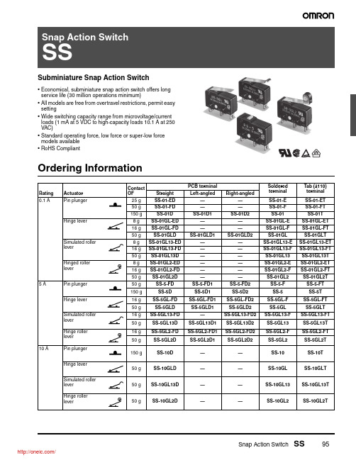
Snap Action Switch SS95Subminiature Snap Action Switch•Economical, subminiature snap action switch offers long service life (30 million operations minimum)•All models are free from overtravel restrictions, permit easy setting•Wide switching capacity range from microvoltage/current loads (1 mA at 5 VDC to high-capacity loads 10.1 A at 250 VAC)•Standard operating force, low force or super-low force models available •RoHS CompliantOrdering InformationRatingActuator Contact OF PCB terminalSoldered terminal Tab (#110) terminal Straight Left-angled Right-angled0.1 APin plunger25 g SS-01-ED ——SS-01-E SS-01-ET 50 g SS-01-FD ——SS-01-F SS-01-FT 150 gSS-01D SS-01D1SS-01D2SS-01SS-01T Hinge lever8 g SS-01GL-ED ——SS-01GL-E SS-01GL-ET 16 g SS-01GL-FD ——SS-01GL-F SS-01GL-FT 50 gSS-01GLD SS-01GLD1SS-01GLD2SS-01GL SS-01GLT Simulated roller lever 8 g SS-01GL13-ED ——SS-01GL13-E SS-01GL13-ET 16 g SS-01GL13-FD ——SS-01GL13-F SS-01GL13-FT 50 g SS-01GL13D ——SS-01GL13SS-01GL13T Hinged roller lever8 g SS-01GL2-ED ——SS-01GL2-E SS-01GL2-ET 16 g SS-01GL2-FD ——SS-01GL2-F SS-01GL2-FT 50 g SS-01GL2D ——SS-01GL2SS-01GL2T 5 APin plunger 50 g SS-5-FD SS-5-FD1SS-5-FD2SS-5-F SS-5-FT 150 g SS-5D SS-5D1SS-5D2SS-5SS-5T Hinge lever 16 g SS-5GL-FD SS-5GL-FD1SS-5GL-FD2SS-5GL-F SS-5GL-FT 50 g SS-5GLD SS-5GLD1SS-5GLD2SS-5GL SS-5GLT Simulated roller lever 16 g SS-5GL13-FD —SS-5GL13-FD2SS-5GL13-F SS-5GL13-FT 50 g SS-5GL13D SS-5GL13D1SS-5GL13D2SS-5GL13SS-5GL13T Hinge roller lever16 g SS-5GL2-FD SS-5GL2-FD1SS-5GL2-FD2SS-5GL2-F SS-5GL2-FT 50 g SS-5GL2D SS-5GL2D1SS-5GL2D2SS-5GL2SS-5GL2T 10 APin plunger 150 g SS-10D ——SS-10SS-10T Hinge lever 50 g SS-10GLD ——SS-10GL SS-10GLT Simulated roller lever 50 gSS-10GL13D——SS-10GL13SS-10GL13THinge roller lever50 g SS-10GL2D ——SS-10GL2SS-10GL2T96Snap Action Switch SSModel Number LegendSpecifications■CharacteristicsNote:1.Data shown are of initial value.2.The dielectric strength values shown is measured using a separator between the switch and metal mounting plate.3.For pin plunger models, the above value apply for use at the free position and total travel position. For the lever models, the values apply at the total travel position.Operating speed 0.1 mm to 1 m/second (pin plunger models)Operating frequency Mechanical: 400 operations per minute max.Electrical: 30 operations per minute max.Insulation resistance 100 M Ω at 500 VDC Contact resistance150 gf:SS-10, SS-5 models:30 m Ω max.SS-01 models:50 m Ω max.50 gf:SS-5 models:50 m Ω max.SS-01 models 100 m Ω max.25 gf:SS-01 models150 m Ω max.Dielectric strength (See note 2)1,000 VAC (600 VAC for SS-01), 50/60 Hz for 1 minute between terminals of same polarity1,500 VAC, 50/60 Hz for 1 minute between current-carrying metal parts and ground and between each terminal and noncurrent-carrying metal parts Vibration resistance (see note 3)Malfunction: 10 to 55 Hz, 1.5 mm double amplitude Shock resistance (see note 3)150 gf: Destruction: 1,000 m/s 2 (approx. 100G) max.Malfunction: 300 m/s 2 (approx. 30G) max.50 gf and 25gf:Destruction: 500 m/s 2 (approx. 50G) max.Malfunction: 200 m/s 2 (approx. 20G) max.Degree of protectionIEC IP40Degree of protection against electric shockClass I Proof tracking index (PTI)175Ambient operating temperature -25° to 85°C (at 60% RH max.) with no icing Ambient operating humidity 85% max. (for 5°C to 35°C)Service lifeMechanical:30 million operations min. at 60 operations per minute (SS-01, SS-5)10 million operations min. at 60 operations per minute (SS-10)Electrical:200,000 operations min. at 30 operations per minute (SS-01, SS-5)50,000 operations min. at 30 operations per minute (SS-10)WeightApprox. 1.6 g pin plunger typeSnap Action Switch SS97■Ratings (reference values)Note:1.Data in parentheses apply to the SS-10 models only.2.The above current ratings are the values of the steady-state current.3.Inductive load has a power factor of 0.4 min. (AC) and a time constant of 7 ms max. (DC). The inductive load rating of the SS-10 is the same as that of SS-5.mp load has an inrush current of 10 times the steady-state current5.Motor load has an inrush current of 6 times the steady-state current.6.If the switch is used in a DC circuit and is subjected to inrush current or surge, connect a surge suppressor across the switch.7.The electrical rating applies under the following test conditions:Ambient T emperature = 20±2°C, Ambient Humidity = 65±5%, Operating frequency = 30 operations/minute■Approved StandardsUL Recognized (File No. E41515) CSA Certified (File No. LR21642)EN61058-1 - - VDE approval(File No. 129246 for SS-5, 125256 for SS-10)EN61058-1 - - TÜV Rheinland approval (File No. J9451450)T esting conditions: 5E4 (50,000 operations), T85 (0°C to 85°C)Note:The rated values approved by each of the safety standards(e.g. UL, CSA) may be different from the performance charac-teristics individually defined in this catalog.■Contact SpecificationsNote:Minimum applicable loads are indicated by N standard refer-ence values. This value represents the failure rate at a 60%(λ60) reliability level (JIS C5003).The equation λ60=0.5 x 10⁻⁶ / operations indicates that a failure rate of 1/2,000,000 operations can be expected at a reliability level of 60%Switch series:Contact form SS-10 and SS-5SS-01Resistive loadLamp loadInductive load Motor load Resistive LoadNCNONC NO NCNONC NO NCNO125 VAC 5 A (10.1A) 1.5 A 0.7 A 3 A 2.5 A 1.3 A 0.1 A 250 VAC 3 A (10.1A) 1 A0.5 A2 A1.5 A0.8 A- - -8 VDC 5 A (10.1A) 2 A 5 A4 A 3 A 0.1 A 14 VDC5 A (10.1A)2 A 4 A3 A 0.1 A 30 VDC4 A 2 A 3 A 3 A 0.1 A 125 VDC 0.4 A 0.05 A 0.4 A 0.05 A - - -250 VDC0.2 A0.03 A0.2 A 0.03 A- - -Rated Voltage SS-10SS-5SS-01125 VAC - - - 5 A 0.1 A 250 VAC 10.1 A 3 A - - -30 VDC- - -- - -0.1 ARated Voltage SS-10SS-5250 VAC10.1 A5 ARated Voltage SS-10SS-5250 VAC10.1 A5 AItem SS-10SS-5SS-01Specification Rivet Crossbar Material Silver alloy Silver Gold alloy Gap (standard value)0.5 mm 0.25 mm Inrush current N C: 20A max.N O: 15A max.N C: 20A max.N O: 10A max.1A max.Minimum applicable load (see note)160 mA at 5 VDC 1 mA at 5 VDC98Snap Action Switch SSEngineering Data■■■MountingPanel MountingAll switches may be panel mounted using M2.3 mounting screws withplane washers or spring washers to securely mount the switch.Tighten the screws to a torque of 0.23 to 0.26 N ·m.PCB LayoutContact Form* Consult Omron for SPST -N C and SPST -N O contact form types ordering information.O v ertra v el (mm)40,00030,00020,00010,0005,0000.10.20.30.40.50.60.7Am b ient temperat u re: 20±2°CAm b ient h u midity: 65±5%W itho u t loadOperating fre qu ency: 60 operations/minS w itching c u rrent (A)5,0003,0001,00050030010050301001234567125 V AC250 V ACAm b ient temperat u re: 20±2°C Am b ient h u midity: 65±5%Operating fre qu ency: 30 operations/min cos φ = 1T w o, 2.4-dia. mo u nting holes or M2.3 scre w holes9.5 ± 0.1Three, 1.35 to 1.5 dia.8.8+0.15–0.05(1.6)16.1±0.1SPST-NCSPST-NOCOM NC COM NO NC COM NOSnap Action Switch SS99Dimensions■TerminalsNote:1.Unless otherwise specified, all units are in millimeters and a tolerance of ±0.4 mm applies to all dimensions2.T erminal plate thickness is 0.5 mm for all models.■Dimensions and Operating CharacteristicsNote:1.Unless otherwise specified, all units are in millimeters and a tolerance of ±0.4 mm applies to all dimensions2.The following illustrations and dimensions are for solder terminal models.Refer to “Terminals” for models with quick-connect terminals (#110) or PCB terminals.3.Terminal plate thickness is 0.5 mm for all models.PCB TerminalsNO terminalNC terminalNO terminalNC terminalNO terminalNC terminal8.87.39.5±0.119.83.30.60.53.28.87.39.5±0.119.83.26.48.87.39.5±0.119.83.22.35+0.075–0.05dia. holes2.35+0.075–0.05Three, 1.6 dia.10.29.57.52PTOP 6.42.92.5 1.68.87.35.119.82.5±0.07 dia.3.26.43.26.49.5±0.1ACharacteristics Part numberSS-01-E SS-01-F, SS-5-F SS-01, SS-5SS-10OF max.25 g 50 g 150 g 150 g RF min. 2 g 4 g 25 g 25 g PT max.0.5 mm 0.5 m 0.5 mm 0.6 mm OT min.0.5 mm 0.5 mm 0.5 mm 0.4 mm MD max.0.1 mm 0.1 mm 0.1 mm0.12 mmOP8.4 ± 0.5 mm100Snap Action Switch SSSS-10GL2.35+0.075–0.05Three, 1.6 dia.t = 0.3(see note 1) 2.35+0.075–0.05dia. holes6.43.26.43.614.5 (see note 2)FPOP10.29.52.5±0.07 dia.2.52.98.87.35.1Note: 1.Stainless-steel le 2.Besides the SS-GL models w ith a hinge le v er length of 14.5, the SS-GL11 models w ith a hinge le v SS-GL111 models ith a hinge le v er length of 22.6, and the SS-GL1111 models w ith a hinge le v er length of 37.Contact yo r OMRON representati v e for these models19.89.5±0.11.6ACharacteristics SS-01GL-E SS-01GL-F, SS-5GL-F SS-01GL, SS-5GL SS-10GL OF max.8 g 16 g 50 g 50 g RF min.1 g 2 g 6 g 6 g OT min. 1.2 mm 1.2 mm 1.2 mm 1.0 mm MD max.0.8 mm 0.8 mm 0.8 mm 1.0 mm FP max.13.6 mm OP 8.8 ± 0.8 mmSimulated Roller Lever Models2.35+0.075–0.05Three, 1.6 dia.2.35+0.075–0.05dia. holes1.3Rt = 0.3 (see note)2.5±0.07 dia.FPOP10.29.5 6.43.26.43.68.87.35.115.82.52.9Note:Stainless-steel spring le 19.89.5±0.11.6A Characteristics SS-10GL13-E SS-10GL13-F, SS-5GL13-F SS-01GL13, SS-5GL13SS-10GL13OF max.8 g 16 g 50 g 50 g RF min.1 g 2 g 6 g 6 g OT min. 1.2 mm 1.2 mm 1.2 mm 1.0 mm MD max.0.8 mm 0.8 mm 0.8 mm 1.0 mm FP max.15.5 mm OP 10.7±0.8 mme Roller Lever ModelsSS-10GL2Three, 1.6 dia.2.35+0.075–0.05dia. 2.35+0.075–0.05dia. holes4.8 dia. (see note 2)Note:1.Stainless-steel spring le2.Polyacetal resin roller2.5±0.07 dia.t = 0.3(see note 1)2.52.914.5FPOP10.29.5 6.48.87.35.119.83.26.49.5±0.11.6ACharacteristics SS-01GL2-E SS-01GL2-F, SS-5GL2-F SS-01GL2, SS-5GL2SS-10GL2OF max.8 g 16 g 50 g 50 g RF min.1 g 2 g 6 g 6 g OT min. 1.2 mm 1.2 m 1.2 mm 1.0 mm MD max.0.8 mm 0.8 mm 0.8 mm 1.0 mm FP max.19.3 mm OP 14.5 ± 0.8 mmSnap Action Switch SS101PrecautionsBe sure to read the precautions and information common to all Snap Action and Detection Switches, contained in the T echnical User’s Guide, “Snap Action Switches, Technical Information” for correct use.■Correct UseMountingMount the switch onto a flat surface. Mounting on an uneven surface may cause deformation of the switch, resulting in faulty operation or breakage in the housing.Operating StrokeT ake particular care in setting the operating stroke for the pin plunger models. Make sure that the operating stroke is 70% to 100% of the rated OT distance. Do not operate the actuator exceeding the OT dis-tance, otherwise the life expectancy of the switch may be shortened.Using MicroloadsUsing a model for ordinary loads to switch microloads may result in faulty operation. Instead, use the models that are designed for microloads and that operate in the following range;However, even when using microload models within the operating range shown above, if inrush current or inductive voltage spikes occur when the contact is opened or closed, then contact wear may increase and so decrease the service life. Therefore, insert a contact protection circuit where necessary.■CautionsHandlingTurn OFF the power supply before mounting or removing the switch,wiring, or performing maintenance for inspection. Failure to do so may result in electric shock or burningTerminal ConnectionWhen soldering the lead wire to the terminal, first insert the lead wire conductor through the terminal hole and then solder.Make sure that the capacity of the soldering iron is 60 W maximum.Do not take more than 5 seconds to solder the switch terminal.Improper soldering involving an excessively high temperature or excessive soldering time may deteriorate the characteristics of the switch.Be sure to apply only the minimum required amount of flux. The switch may have contact failures if flux intrudes in the interior of the switch.Use the following lead wires to connect to the solder terminals;If the PCB terminal models are soldered in a solder bath, flux will per-meate inside the switch and cause contact failure. Therefore, manu-ally solder the PCB terminal.Wire the quick-connect terminals (#110) with receptacles. Insert the terminals straight into the receptacles. Do not impose excessive force on the terminal in the horizontal direction, otherwise the termi-nal may be deformed or the housing may be damaged.Insulation DistanceUse a separator between the switch and metal mounting panels, to ensure proper dielectric characteristics are achieved.According to E N 61058-1, the minimum insulation thickness for this switch should be 1.1 mm and minimum clearance distance between the terminal and mounting plate should be 1.6 mm. If the insulation distance cannot be provided in the product incorporating the switch,either use a switch with insulation barrier or use a separator toensure sufficient insulation distance.Operating range for micro load models SS-01Operating range for general-load modelsSS-5, SS-10C u rrent (mA)V o l t a g e (V )Inopera b le range 3024121,0001001015100mA100mA 160mA26mA 1mA0.16mA Model Conductor size SS-50.5 to 0.75 mm 2SS-100.75 mm 2Snap Action Switch SSOMRON ON-LINEGlobal - USA - Cat. N o. X303-E-1Printed in USAOMRON ELECTRONIC COMPONENTS LLC55 E. Commerce Drive, Suite B Schaumburg, IL 60173847-882-228811/10 Specifications subject to change without noticeAll sales are subject to Omron Electronic Components LLC standard terms and conditions of sale, which can be found at /components/web/webfiles.nsf/sales_terms.html ALL DIMENSIONS SHOWN ARE IN MILLIMETERS.T o convert millimeters into inches, multiply by 0.03937. T o convert grams into ounces, multiply by 0.03527.分销商库存信息:OMRONSS-01GL111SS-01GL111D SS-5GLD-12SS-01GL30PT SS-5GL11SS-5GL111SS-5GL1375-3T BY OMI SS-5GL111-F SS-5GL111TSS-5GL1111T BY OMI SS-5GL111-FT SS-5GL1131TSS-5GL1131SS-5GL1140-3SS-5GL1138 BY OMI SS-5GL1112T SS-01GL1131SS-5GL111-FDSS-5GL1129D SS-5GL1144D SS-01GL111-FTSS-5GL1111D2SS-01GL111-E SS-5GL1111SS-01GL11SS-01GL11-F SS-5GL111-FD2SS-01GL1131-ET SS-01GL1140T SS-5GL111D1SS-01GL1111D SS-01GL111T SS-01GL111-ED1 SS-5GL111-FD1SS-01GL111-ED SS-01GL111-ETSS-01GL111-FD1SS-5GL1170-3SS-1-4。

ASTM A403标准--奥氏体不锈钢管件标准规定1:标准范围1.1本标准包含压力管道上用的制造不锈钢管件规定。
1.2本标准涉及到几种等级的奥氏体不锈钢。
根据ASME或MSS标准上的尺寸及压力等级,本标准把不锈钢钢管件的等级采用加前缀WP或CR表示。
1.4 本标准采用英寸-磅和SI公制两套单位。
但是,如果合同上没有规定采用SI公制单位,那么材料应当以英寸-磅表示。
1.5无论英制还是公制,都应单独使用。
本标准内容中,SI公制单位在括号中显示。
在数值上,英制和公制数值并不能精确地互相对等。
所以,每套单位体系应单独使用,而不与另一套体系混淆使用。
如果混合使用两种单位体系,则有可能导致不能满足本标准的具体要求。
1.6本标准不适用于铸钢管件。
对于奥氏体铸钢管件的要求,见A 351、A743及A 744三个标准。
2 参考索引标准2.1 ASTM标准A262 (奥氏体不锈钢晶间腐蚀的敏感性测试)A370 刚产品的力学性能测试A388 锻件的UT检测A480 轧制不锈钢板材、耐热钢板的通用要求A960 加工管件的通用要求2.1 ASME标准ASME B16.9对焊管件ASME B16.11承插口焊接管件及螺纹接口管件ASME B16.5(6.4.4里规定了法兰水文线和粗糙度)2.3 MSS标准MSS-SP43小不锈钢对接焊接管件标准2.4 ASME锅炉压力容器规范VIII DIV1ASME IX焊接评定(IX卷上,焊工钢印的相关规定)2.5 AWS标准(焊材)2.6 ASNT 无损检测标准3.通用要求及订货规定3.1按本标准生产的管件须满足A960标准及采购合同中的补充要求。
如果不能满足A960,那么也将视为不满足本标准。
执行中间,一旦本标准和A960有冲突,那么应优先执行本标准。
3.2 当以本标准作为管件采购依据时,A960标准则作为订货技术文件,需要同时满足。
4 材料4.1 管配件所用材料可由锻件、圆钢、板材或无缝/有缝管材。

中国机车远程监测与诊断系统(CMD系统)车地数据传输技术王强;唐国平【摘要】机车运行在不同地域和不同场景,如何将大量车载数据及时发送到中国机车远程监测与诊断系统(CMD系统)地面综合应用系统是CMD系统的关键技术之一,已知车地无线通信技术如GSM-R、3G/4G、WLAN、卫星通信等均存在一定局限性,通过对上述技术进行比较,以及分析CMD系统数据传输的应用需求,提出一种适用于铁路运营环境的车地无线传输综合技术及相应的传输策略.【期刊名称】《中国铁路》【年(卷),期】2017(000)003【总页数】5页(P23-27)【关键词】机车;远程监测;诊断;CMD系统;车地无线通信;数据传输;WLAN;北斗通信【作者】王强;唐国平【作者单位】中国铁路总公司运输局,北京 100844;株洲中车时代电气股份有限公司,湖南株洲412001【正文语种】中文【中图分类】U26;TP277中国机车远程监测与诊断系统(CMD系统)中,如何将机车在运行中产生的大量车载实时数据、运行记录数据、视频信息及时发送到CMD地面综合应用系统,实现对机车远程实时监测和诊断,是CMD系统的关键技术之一。
已知GSM-R铁路移动通信专网、3G/4G移动通信网络、WLAN、卫星通信等车地无线通信技术均存在一定局限性,不能满足CMD系统对车地无缝数据传输的要求。
1.1 移动通信移动通信技术不断发展,经过GSM、3G发展到第四代(4G)的长期演进技术(Long Term Evolution,LTE)。
GSM-R铁路移动通信专网在其覆盖的铁路线路能实现车地无缝数据传输,实时性高,最高传输速率可达171 kb/s,缺点是GSM-R只覆盖部分铁路线路;3G是第三代移动通信技术,能够同时传送声音及数据信息,目前3G有CDMA2000、WC DMA、TD-SCDMA三种标准,速率一般在几百kb/s以上,3G下行速率峰值可达3.6 Mb/s,上行速率峰值可达384kb/s;与3G相比,4G通信系统改善了小区边缘用户性能,提高了小区容量,降低了系统延迟,改进并增强了3G的空中接入技术,采用当前无线通信领域核心技术OFDM和MIMO,4G系统能够提供下行100 Mb/s与上行50 Mb/s的峰值速率,截至2016年6月,我国已建成全球最大的4G网络,4G基站超过200万个。

D3877-US-Rev A May 27, 2010John Deere455/1520/1530Grain DrillScale SystemInstructionsAndRepair PartsFt. Atkinson, Wisconsin USAPanningen, The Netherlands John Deere 750/1560/1590-15 ft Grain Drill D3859-US-Rev A TABLE OF CONTENTSINTRODUCTION ............................................................................................................................................................................................... 1 Charging Battery and Welding ....................................................................................................................................................................... 1 SCALE BRACKET AND LOAD CELL MOUNTING INSTALLATION ................................................................................................................. 2 John Deere Grain Drill Scale Kit .................................................................................................................................................................... 3 Clutch Arm Updates ....................................................................................................................................................................................... 4 JUNCTION BOX MOUNTING ............................................................................................................................................................................ 6 Connect Load Cell and J-Box Cable .............................................................................................................................................................. 6 Installing Wires into Terminal Block ............................................................................................................................................................... 6 INDICATOR MOUNTING ................................................................................................................................................................................... 7 Power Connection: ........................................................................................................................................................................................ 7 Load Cell Connection:.................................................................................................................................................................................... 7 TROUBLE SHOOTING ...................................................................................................................................................................................... 8 How to Check the Drill Scale After Installation ............................................................................................................................................... 8 REPAIR PARTS ................................................................................................................................................................................................ 9 Kit – Scale System – JD455 .......................................................................................................................................................................... 9 Kit – Scale System – JD1520/JD1530 ......................................................................................................................................................... 10 Indicator Swivel Mount ................................................................................................................................................................................. 11 LICENSE AGREEMENT . (12)All rights reserved. Reproduction of any part of this manual in any form whatsoever without Digi-Star’s express written permission is forbidden. The contents of this manual are subject to change without notice. All efforts have been made to assure the accuracy of the contents of this manual. However, should any errors be detected, Digi-Star would greatly appreciate being informed of them. The above notwithstanding, Digi-Star can assume no responsibility for errors in this manual or their consequence. © Copyright! 2008 Digi-Star, Fort Atkinson (U.S.A.).D3859-US-Rev A John Deere 750/1560/1590-15 ft Grain Drill 1INTRODUCTIONCongratulations on the purchase of your new Digi-Star Grain Drill Scale System. This scale system is specifically designed to weigh the seed hopper on a John Deere 455/1520/1530 Grain Drill. The scale kit can be used to record and monitor seed weight going into or out of the seed hopper. This scale system is covered by the following US patents: 6732667, 7059258 and 7273017. The single-use license is included with this document (see page 12). This SAFETY ALERT SYMBOL indicates important safety messages in the manual. When you see this symbol, be alert to the possibility of PERSONAL INJURY and carefully read the message that follows.NEVER OPERATE WITHOUT ALL COVERS, SHIELDS AND GUARDS IN PLACE. KEEP HANDS, FEET AND CLOTHING AWAY FROM MOVING PARTS. FAILURE TO HEED MAY RESULT INSERIOUS PERSONAL INJURY OR DEATH. Some covers and guards have been removed for illustrative/photographic purposes only in this manual. For information on ordering repair parts, refer to Parts Section in this book. This supersedes all previous published instructions.Important!Charging Battery and WeldingDisconnect all cables from the weighing indicator before charging the battery or welding on the machine. Ifcables are left connected, the weighing indicator and connected load cells could be damaged.Important: Do not weld near indicator, load cells or cables; remove from area to be welded. Place ground close to area to be welded to prevent current from passing through electronic parts.Scale Indicator Remote Indicator OptionalJ-Box2 John Deere 750/1560/1590-15 ft Grain Drill D3859-US-Rev A SCALE BRACKET AND LOAD CELL MOUNTING INSTALLATIONThe John Deere 455/1520/1530 Grain Drill Scale Kit consists of mounting four load cells, J-Box and scale indicator to support the seed hopper. 1. On the right side, as you are facing forward looking at the tractor, loosen the four 7/16 bolts that hold the seed bin to the frame.2. On the left side, remove the 7/16 bolts that hold the seed bin to the frame.3. Use a jack to lift the left bin side up; use a 4” x 4” or 4” x 6” board. Support the 4” x 4” or 4” x 6” board with the walkway and the front frame. Put your jack between the board and the bottom of the seed bin.It is recommended the hopper be supported by two methods when installing the load cells and brackets. In addition to lifting the hopper with a chain or nylon strap, the hopper should be supported in the middle with a hydraulic jack or stands.Important: The lifting chains, bucket attachments, loader/skid steer or winch must be capable of lifting and controlling 1000 lbs.4. Jack up the bin 5”.5. Install the bottom bracket with 7/16 x 1.5” bolt and 7/16 x 1.5” socket head cap screws. IMPORTANT : The 7/16 socket head cap screws are mounted in the countersink holes in the lower bottom bracket. Leave the bolts loose at this time.6. Install the top bracket with 7/16 x 1.5” bolt and 7/16 x 1.5 socket head cap screw. IMPORTANT: The 7/16 x 1.5” socket head cap screws are mounted in the countersink holes in the upper bracket. Tighten the 7/16 tapered bolts first and then the 7/16 standard bolts.D3859-US-Rev A John Deere 750/1560/1590-15 ft Grain Drill3John Deere Grain Drill Scale Kit4 John Deere 750/1560/1590-15 ft Grain Drill D3859-US-Rev A 7. Slide the load cells into the sockets on the bottom bracket. Slide the load cells all the way into the socket. Stop when the load cell cord is up against the socket. (Load cells with 11 ft cable are in the rear.) IMPORTANT : Decal must point DOWNWARD . See Detail A.8. Lower the seed hopper down slowly and be careful not to cut the load cell cord next to the socket on the bottom bracket. Lower the hopper until the top bracket socket lines up with the bottom load cells. Slide the load cells into the top socket and install 3/8 clevis pin and cotter pin.9. Let the jack down. Do not tighten the bottom bracket bolts at this time.10. Repeat steps 2 – 9 for the right side. IMPORTANT : For JD455 grain drill, disconnect the drive shaft bearing holder, drive chain and clutch arm.11. When both sides are completed, tighten the bolts on the bottom bracket. Tighten the tapered bolts first and then the standard hex head bolts.Clutch Arm UpdatesTo make room for the load cells, the hopper was raised upward by approximately 4”. As a result, the drive lineclutch must be modified. There are two types of updates depending on your grain drill series.D3859-US-Rev A John Deere 750/1560/1590-15 ft Grain Drill 5JD455 Clutch Arm Updates1. Mount the drive shaft bearing holder provided with the kit. Weld the bottom bracket to the drill frame when the shaft looks straight.2. Install the chain tightener provided with the kit (you may need to shorten the chain).3. Install the new clutch drive arm. Drill a hole in the arm so the clutch is disengaged when the drill is up and engaged when the drill is down. The length extended on the clutch arm is the same distance that the seed bin was raised, because of the scale system.JD1520/1530 Clutch Arm Updates1. Switch space (number 1) with gear (number 2).2. Remove bolts on end bearing holder and slide main shaft (number 3) away from tank.3. Remove sprocket and role pin, then slide the bearing on first.4. Install bearing holder close to the inside of the sprocket.5. Line up the chain so the sprocketswill be straightwith each other. Make sure theshaft does not touch the tank. 6. A hole will have to be drilled in the gusset on the frame to get the U-bolt to go in (number 4).6 John Deere 750/1560/1590-15 ft Grain Drill D3859-US-Rev A JUNCTION BOX MOUNTINGThe junction box is water resistant, not water-proof. It should be mounted to avoid submersion during wet weather and to avoid physical abuse. The junction box can be mounted on the front or rear of the drill, planter or seeder. All load cell cables must reach the J-Box. Install by removing the double sided tape backing and apply to cleaned surface.Connect Load Cell and J-Box Cable 1. Route front and rear load cell cables to J-box location. Make sure they are not bound or pinched. Cable tie (customer provided) load cell cables in place. 2. Insert load cell and J-box cables through each of the water-tight strain-reliefs. 3. Remove each terminal block from the J-box. 4. Connect wires of the same color to the same terminal block as shown above. See instructions below. 5. Install terminal block into the J-box as shown (location not important). 6. Tighten nuts on the water-tight strain-reliefs. 7. Assure that gasket is properly installed in the cover. 8. Attach cover using 4 screws (provided). Installing Wires into Terminal Block 1. Open levers 90º to locked position. 2. Insert individual wires into terminal. 3. Close lever. 4. Tug wire to assure solid connection. Note: Wire strip length is 7/16” (11mm). 406232 J-Box Lever Nut 4Pt (Planter) 141837 Cable - 30Ft J-Box 406074 Cable - 45Ft J-Box 403335 Cable - Power 17Ft 2-Wire 406073 Cable - Power 36Ft 2-Wire 406072 Cable - Power 6Ft 2-Wire 824316 Cable - 15Ft-J-Box 145096 Cable - 70Ft-J-Box 406276 Cable – Power 65Ft 2-WireStrain ReliefD3859-US-Rev A John Deere 750/1560/1590-15 ft Grain Drill 7INDICATOR MOUNTINGThe scale indicator can be mounted in the tractor cab or on the drill with swivel mounting pack (406081). Two cables must be connected to the indicator bottom panel, J-Box and power cables. Refer to Indicator Manual D3831-US for details of indicator mounting options and connection of power cord. 1. Bolt the readout in the cab with the bracket, or mount the bracket in the front of the lift cylinder. 2. Install power cord to a 12-volt negative ground battery. 3. Route J-box cable to indicator and install to indicator bottom panel. 4. Program indicator with set-up #145015 and calibration #14000 (see Indicator Manual)Power Connection:The power cable should be connected directly to a vehicle battery or regulated power supply. The scale end of the power cable is attached to the J901 connector located on the bottom panel of the indicator. Connect the RED wire from the power cable to +12 VDC and the BLACK wire to GROUND. The indicator is fused internally at 4 amps. Power Cable Connections: Wire color Wire Function Red Battery (+12 VDC) Black GROUNDLoad Cell Connection:The indicator is designed to operate with strain gage load cells. The indicator will normally be supplied with a “J-BOX” cable going between the scale and the load cell junction box. Load Cell Wire Digi-StarFunction1RED+EX2GREEN-SIG3WHITE +SIG 4 BLACK -EX 5 CLEAR SHIELDTRACTOR CAB MOUNTING INDICATOR MOUNTINGS DRILL MOUNTING8 John Deere 750/1560/1590-15 ft Grain Drill D3859-US-Rev A TROUBLE SHOOTINGHow to Check the Drill Scale After InstallationFor the first test, lift the drill all the way up, to a level area. Put 200-250 pounds of weight on the right side, then compare it to the left. Both sides should be within four to six pounds of each other. • If the weight is not within the four to six pound range, the drive chain might be too tight or the clutch is binding. Loosen the chain and check the weight again. • If loosening the chain does not fix the problem, you must remove the clutch arm, and then check the weight on both sides. NOTE : The clutch arm needs to be on the back of the clutch to work properly. The second test is to lift the drill to a level area and zero the scale. Lift the drill up and down two to three times, checking to see if the scale zeros out. Each time the scale is in the up position, it should be within four to six pounds. If not, remove the clutch arm and repeat the test. If this solves the weigh problem, the clutch is binding or it needs lubrication. NOTE : The clutch arm needs to be on the back of the clutch to work properly. If further assistance is necessary, please call Digi-Star, LLC at 920-563-9700.REPAIR PARTSKit – Scale System – JD455KEY QTY. PARTNO. DESCRIPTION KEY QTY. PARTNO. DESCRIPTION1 2 406403 Weld-Bottom LC Mnt 9 8 406414 SCR-7/16-14 x 1.5 HHCS Grd 52 2 406406 Weld–Top LC Mnt 10 2 406401 SCR-3/8-16 x 1.5 HHCS ZPGrd 53 1 406397 Angle–Brg Holder Bottom 11 2 406400 Wash-3/8 Flat Type A Wide ZP4 1 406396 Plate-Bearing Holder Top 12 8 406416 Nut-7/16-14 Ser Flange ZP5 1 406402 Bar-Clutch Arm 13 2 404705 Nut-3/8-16 Ser Flange ZP6 4 405897 Pin-Cotter 5/32 x 1.0 ZP 14 2 400373 Cell-1.5 DB-11 Ft7 4 405860 Pin-Clevis 3/8 x 2.25 ZP 15 2 400400 Cell-1.5 DB-16 Ft8 8 406415 SCR-7/16-14 x 1.5 FSHBlkKit – Scale System – JD1520/JD1530KEYQTY.PART NO.DESCRIPTION KEY QTY.PART NO.DESCRIPTION1 2 406403 Weld-Bottom LC Mnt (JD455)9 8 406414 SCR-7/16-14 x 1.5 HHCS Grd 5 2 2 406406 Weld–Top LC Mnt (JD455)10 2 406401 SCR-3/8-16 x 1.5 HHCS ZPGrd 53 1 406396 Plate-Bearing Holder Top 11 2 406400 Wash-3/8 Flat Type A Wide ZP4 1 406489 Brkt-Brg Suppt (JD1520/1530)12 8 406416 Nut-7/16-14 Ser Flange ZP 5 1 406490 Bolt-U 1/2-13 x 5-625W x 8.375L Gr5 ZP13 2 406085 Nut-1/2-13 Ser Flange ZP 6 4 405897 Pin-Cotter 5/32 x 1.0 ZP 14 2 404705 Nut-3/8-16 Ser Flange ZP 7 4 405860 Pin-Clevis 3/8 x 2.25 ZP 15 2 400373 Cell-1.5 DB-11 Ft 88406415SCR-7/16-14 x 1.5 FSH Blk162400400 Cell-1.5 DB-16 FtIndicator Swivel Mount406081KEYQTY.PART NO.DESCRIPTION1 1 403980 Brkt – Robo Mtg2 2 406086 Brkt – Swivel Cast (JD H161618)3 2 406087 Gasket – 1.813OD x 1.218 ID x .313 WID4 2 400036Scr – 1/4-20 x 3/4 HHCS ZP5 2 400038Washer – Lock 1/4 ZP6 2 400035Nut – 1/4-20 ZP7 2405989 Scr – 3/8-16 x 3.0 HHCS ZP Grd 5 8 2 404292 Nut – 3/8-16 Nyloc ZP92405612GT400 Indicator (Not included in kit 406081)406385KEYQTY.PART NO.DESCRIPTION1 1 404230 Ram Suction Cup with Twist Lock2 2 403180 Assembly – 1” Ram Mount32403779 Scr - #10 x 5/8 PHSTS 48-2 Blk ZP321LICENSE AGREEMENTIMPORTANT NOTICE: Acceptance and use of the enclosed electronic scale products (hereinafter referred to as “Purchased Product”) constitutes your agreement to the following terms and conditions. Please carefully read the following terms and conditions before using or reselling the Purchased Product.1.Limited License. Digi-Star, LLC, a Wisconsin limited liability company(“Owner”) is the owner of the following U.S. Patents related to grain drills: 6,732,667, 7,059,258, 7,273,017, 7,357,087, 7,448,335, 7,523,710 and any other patents which result from continuation applications thereof (“Patents”). Owner hereby grants to the customer (“Customer”) a non-exclusive, non-transferable, revocable, limited license to use the technology described in the Patents to use the Purchased Product to assemble a seed planter product covered by the Patents (“Licensed Product”), and to sell and offer for sale one (1) unit of the Licensed Product in accordance with the terms and conditions set forth herein. Alternatively, Customer may resell the Purchased Product to another entity for the purpose of that entity assembling one (1) unit ofa Licensed Product under a permitted sublicense from the Customerwith the same terms as this Agreement. If Customer would like to assemble, use, sell or offer for sale more than one (1) Licensed Product, or resell more than one (1) Purchased Product, Customer understands and agrees that it must purchase another Purchased Product from Owner or acquire a separate license by requesting and purchasing another unit of the same SKU number that resulted in this purchase.2.Acceptance of Terms and Conditions. Customer warrants that it has theauthority to enter into this binding agreement. If Customer does not accept the terms and conditions, Customer shall not use the Purchased Product. Customer understands and agrees that if it uses the Purchased Product as permitted herein, it will be deemed to have accepted these terms and conditions and they shall become a binding agreement.3.Limitations on Use. Customer agrees that it will use the LicensedProduct only as expressly authorized in this Agreement, and that any use not expressly authorized in this Agreement is prohibited. Customer agrees that it will not: (i) loan, rent, lease, assign, sublicense, distribute or otherwise transfer its rights under this Agreement to a third party, other than to resell the Purchased Product to another entity for the purpose of that entity assembling one unit of a Licensed Product; (ii) copy or reproduce the Licensed Product; or (iii) grant any sublicenses other than to an end user of the Licensed Product, or to another entity for the purpose of that entity assembling one unit of a Licensed Product.Customer agrees to use reasonable efforts to prevent any unauthorized use or copying of the Licensed Product and will notify Owner immediately upon learning of any such unauthorized use or copying.Customer’s obligations under this section shall survive any termination of this Agreement or the license granted hereunder. Any unauthorized use of the Licensed Product will result in, among other things, the immediate termination of this license.4.Ownership of Proprietary Rights. Customer acknowledges that theLicensed Product is covered intellectual and/or proprietary rights, and that all such intellectual and proprietary rights are owned by Owner.Customer hereby acknowledges that it has no rights in the foregoing except as expressly granted herein.5.NO WARRANTY. Customer agrees to fully test and evaluatethe Purchased Product and Customer acknowledges and agrees that Owner will not assume any product liability or any otherliability for the Purchased Product or the Licensed Product. The Purchased Product is furnished to Customer “AS IS.” Except as otherwise provided by separate documentation, OWNER MAKES NO WARRANTIES, EITHER EXPRESS OR IMPLIED, WITH RESPECT TO THE PURCHASED PRODUCT. Customer agrees that Owner shall have no liability resulting from Customer’s use of the Purchased Product for any indirect damages including consequential, incidental or special damages for loss of profit, good will or otherwise. Customer shall indemnify and hold Owner harmless from any and all losses, expenses, damages, costs or expenses of any kind, including but not limited to reasonable attorneys’ fees, incurred by Owner resulting from Customer’s use of the Purchased Product. NO ORAL OR WRITTEN STATEMENTS MADE BY OWNER OR ITS EMPLOYEES INCLUDING BUT NOT LIMITED TO STATEMENTS REGARDING CAPACITY, SUITABILITY FOR USE, OR PERFORMANCE OF THE PURCHASED PRODUCT SHALL BE DEEMED A WARRANTY OR REPRESENTATION BY OWNER FOR ANY PURPOSE NOR GIVE RISE TO ANY LIABILITY OR OBLIGATION OF OWNER.6.Remedies for Violations. Owner reserves the right to seek allremedies available at law and in equity for violations of this Agreement, including but not limited to the right to recover the Licensed Product.7.Fees. In consideration for the rights granted under thisAgreement, Customer has paid a license fee that was included in the amount invoiced to the Customer for the sale of the Purchased Product.8.Entire Agreement. Except as expressly stated herein to thecontrary, this Agreement constitutes the entire agreement between the parties regarding the subject matter hereof, and no verbal or written prior statements or representations of any sort made by any party shall be effective or valid for any purpose whatsoever. This Agreement may be amended only upon the mutual consent of all parties in writing.9.Severability. If any provision of this Agreement shall be held tobe invalid, illegal or unenforceable, the validity, legality and enforceability of the remaining provisions shall not in any way be affected or impaired thereby. The failure of any party to enforce any provision of this Agreement shall not be considereda waiver thereof, nor shall such failure prevent the futureenforcement of any such provision.erning Law. This Agreement and the relationship betweenthe parties shall be governed in all respects by the laws of the State of Wisconsin and the United States of America. The parties consent to the jurisdiction and venue of the Wisconsin and United States courts located in Wisconsin for resolution of any dispute under to this Agreement.Use or sale of the Licensed Product or of Purchased Product shall bind Customer to all terms and conditions herein without the necessity of signatures on this Agreement.。


●弯头 elbow异径弯头 reducing elbow带支座弯头 base elbow长半径弯头(标准1。
5倍弯曲半径---1.5D)long radius elbow●三通 tee异径三通 reducing tee等径三通 straight tee带侧向口的三通(右向或左向) side outlet tee (right hand or 1eft hand)异径三通(分支口为异径) reducing tee (reducing on outlet)异径三通(一个直通口为异径)reducing tee (reducing on one run)带支座三通 base tee异径三通(一个直通口及分支口为异径) reducing tee (reducing on one run and outlet)异径三通(两个直通口为异径,双头式) reducing tee (reducing on both runs, bull head)45°斜三通 45° lateral45°斜三通(支管为异径) 45° lateral (reducingon branch)45°斜三通(一个直通口为异径) 45° lateral (reducing on one run)45°斜三通(一个直通口及支管为异径) 45° lateral(reducing on one run and branch)Y型三通(俗称裤衩) true “Y"四通 cross等径四通 straight cross异径四通 reducing cross异径四通(一个分支口为异径)reducing cross (reducing on one outlet)异径四通(一个直通口及分支口为异径) reducing cross (reducing on one run and outlet)异径四通(两个分支口为异径) reducing cross (reducing on both outlet)异径四通(一个直通口及两个分支口为异径)reducing cross (reducing on one run and both outlet)异径管 reducer同心异径管 concentric reducer偏心异径管 eccentric reducer锻制异径管 reducing swage螺纹支管台 threadolet焊接支管台 weldolet承插支管台 sockolet弯头支管台 elbolet斜接支管台 latrolet镶入式支管嘴 sweepolet短管支管台 nipolet支管台,插入式支管台 boss●螺纹支管台Threadolet●弯头支管台elbolet●焊接支管台weldolet;on weld●短管支管台nipolet●承插支管台sockolet●烧焊支管台weldolet●斜接支管台latrolet●承插焊支管台Sockolet●支管台,插入式支管台boss管接头 coupling, full coupling半管接头 half coupling异径管接头 reducing coupling活接头 union内外螺纹缩接(俗称补芯) bushing 管帽 cap (C)堵头 plug短节 nipple异径短节 reducing nipple; swage nipple管道英文缩写A Anchor 固定ABS * Absolute 绝对的AISI *American Iron and Steel Institute 美国钢铁学会ANSI * American National Standards Institute美国国家标准学会API *American Petroleum Institute 美国石油学会APPROX *Approximate 大约,近似的ASB Asbestos 石棉ASME *American Society Of MechanicalEngineers美国机械工程师协会ASSY * Assembly 装配,组装ASTM * American Society Of Testing Material 美国材料实验协会ATM * Atmosphere 大气压AWG * American Wire Gage 美国线规AWS * American Wel**** Society 美国焊接协会AWWA * American Water WorksAssociation 美国水工协会BBB Bolted Bonnet 栓柱连接的阀盖BB By Buyer 买方供货B-B Beveled End—Beveled End 两端为坡口端BC Bolt Circle 螺栓中心圆B。


5- and 15-kV Megohmmeterss Continuously variable test voltage s Rugged field construction sCircuit-breaker protectionDESCRIPTIONThe 5- and 15-kV Megohm-meters are high-voltage, line-operated instruments. They provide a continuously variable test voltage for highly sensitive insulation-resistance measurements of all types of electrical equipment and power cable.The instruments are designed to withstand harsh field conditions, and feature tough, impact-resistance casing,removable lids and adjustable carrying straps. Forcomplete portability, there is ample room in each case to store cables and the instruction manual.APPLICATIONSThe units are suitable for dielectric absorption and step-voltage testing. T wo models are available:The 5-kV Megohmmeter measures up to 100,000 M Ω;provides output from 250 volts to 5 kV , with direct reading up to 50,000 M Ωat 2.5 kV .The 15-kV Megohmmeter provides direct reading measurements up to 100,000 M Ωat 5 kV and up to 200,000 M Ωat 10 kV , with a multiplying factor for all other voltages up to 15 kV .The 15-kV model also features an internal voltagestabilizer that may be activated for improved measurement under extreme field conditions. Separate on/off controls are provided for power and high voltage, and a red light indicates when high voltage is on.FEATURES AND BENEFITSs Provides 2% kV and M Ωaccuracy Guard terminal to eliminate surface leakage current from the measurements Zero-start, high-voltage interlocksShielded, high-voltage output cable permanently connected to the instrument s Circuit-breaker protection s Redundant grounding connections s Easy-to-follow, color-coded meter scalessAnalog metering for monitoring of variable measurementssRugged field construction5-kV Model, Cat. No. 210400Input Voltage 120 Vac, 60 Hz Test Voltage0 to 5 kVdc, negative with respect to ground Output Current 5 mA continuousShort-Circuit Current 12 mA max.InstrumentationKilovoltmeter:4.5-in. (114-mm) taut band Three Color-Coded Scales Red:0 to 2.5 kV Black:0 to 5 kVGreen:0 to 1 reference Accuracy:±2% full scale Megohmmeter4.5-in. (114-mm) taut band T wo Color-Coded Scales Red:0.5 to 50 M ΩBlack:1 to 100 M ΩAccuracy:±0.031 in. (0.08 cm) at any marking Operating Temperature Range 0 to 122º F (–17.7 to +50º C)15-kV Model, Cat. No. 210415Input Voltage 120 Vac, 60 Hz Test Voltage0 to 15 kVdc, negative with respect to ground Output Current2 mA continuous (stabilizer out)50 µA continuous (at 15 kV , stabilizer in)Short-Circuit Current 12 mA max.InstrumentationKilovoltmeter:4.5-in. (114-mm) taut band Three Color-Coded Scales Red:0 to 7.5 kV Black:0 to 15 kVGreen:0 to 1.5 reference Accuracy:±2% full scale Megohmmeter4.5-in. (114-mm) taut band T wo Color-Coded Scales Red:1 to 100 M ΩBlack:2 to 200 M ΩAccuracy:±0.031 in. (0.08 cm) at any marking Operating Temperature Range 0 to 122º F (–17.7 to +50º C)DC Test Megohm Range Multiplier Cat. No.Model Voltage x1x10x100x1000Dimensions Weight 2.5 kV dc 0.5 to 50 5 to 50050 to 5000500 to 50,00010 H x 10.2 W x 14 D in. 20.5 lb 2104005-kV5 kV dc 1 to 10010 to 1000100 to 10,0001000 to 100,000254 H x 260 W x 355 D mm 9.3 kg 250 V to 5 kV Multiply M Ωby factor indicated in green7.5 kV dc1.5 to 15015 to 1500150 to 15,0001500 to 150,00012.5 H x 11.5 W x 20.2 D in.35 lb 21041515-kV15 kV dc 3 to 30030 to 3000300 to 30,0003000 to 300,000317 H x 292 W x 514 D mm15.9 kg500 V to 15 kVActual kV 10x Range at 10 kV SPECIFICATIONSRegistered to ISO 9001:2000 Reg no. Q 09290Registered to ISO 14001 Reg no. EMS 61597MEGOHMMETERS_DS_en_V10。

施耐德电气VDI综合布线产品目录ConnectivitySuperior Usability User Delights Actassi系列,细微之处折射出精心思量的痕迹,富有未来感的海洋设计元素,方寸间凸现精致味道,”超强适用性”更将令您体验到智能科技所赋予我们的无穷乐趣:使您的生活更从容让您的工作事半功倍集科技美感与强大功能于一身彰显细致品位生活人群对高品质生活的追求即时的备选方案使您永无后顾之忧Discover the delights of Superior Usability!尽享“超强适用性”的无穷乐趣!Actassi 意味着“共享整个蓝色海洋”。
当您选择 Actassi 系列作为您的结构化布线方案时,您便开始在智能科技的“蓝色海洋”中自由遨游了。
在这里,连接方式完全以用以用户为中心,安全稳定、功能强大,雅致且简便易用。
徜徉其中,您不仅可以感受Actassi 系列最新的产品理念,更可以无穷乐趣!Connectivity连通性Superior Usability超强适用性User Delights用户的无穷乐趣ID-Tracer TM 智能布线方案 -您布线时的理想方向标光纤解决方案 -使您的系统稳如泰山减少了60%的IT 基础设施的安装时间大型动态网络智能布线方案后视图10G 解决方案 -为您的数据传输添翼扩展的数据应用更快的数据传输10G 解决方案操作更简单,更持久耐用严格的线缆安装条件光纤解决方案科技快速发展的今天,要求IT 专业人士面对网络规划和操作时,必须快速地作出反应。
这些IT 专业人士面临的最大挑战,就是为了新建的或新选址的办公室建立大型的IT 基础设施,并考虑到公司重组时网络管理的变化。
在配线架、局域网控制器和软件几个方面,我们的ID-TracerTM 智能布线解决方案可以确保他们在这样的大型动态网络中,实现高效且可靠的远程布线管理。
随着新型依赖IP 的VoIP 、视频流、现场报道与监控等应用程序的不断面世,确保优异的传输速度、可靠性与成本有效性则变得空前重要。

基于SMOS卫星数据的海表面盐度模型赵红;王成杰【摘要】海表面盐度是研究海洋对全球气候影响以及大洋环流的重要参量之一,而卫星遥感技术是获取海表面盐度数据的最有效方法.目前,L波段的SMOS和Aquarius/SAC-D遥感卫星正在用于探测海表面盐度,并根据卫星观测数据和物理机制反演出海表面盐度的产品.但在某些近陆地区域,由于淡水流入及陆地射频(RFI)等因素影响,卫星反演盐度的产品精度较低.文中利用“东方红2号”科学考察船的实测数据、SMOS卫星数据,首次针对中国南海海域提出了用贝叶斯网络模型计算海表面盐度,并用验证数据集(实测Argo盐度)对模型进行适应性评估.经过计算,模型误差和验证误差分别为0.47 psu和0.45 psu,而相应的SMOS Level 2产品的精度分别为1.90 psu和1.82 psu.此模型为海表面盐度的计算提供了一个新方法.【期刊名称】《海洋技术》【年(卷),期】2016(035)001【总页数】8页(P15-22)【关键词】海表面盐度;SMOS卫星;贝叶斯网络;统计模型【作者】赵红;王成杰【作者单位】中国海洋大学数学科学学院,山东青岛266100;中国海洋大学数学科学学院,山东青岛266100【正文语种】中文【中图分类】P731.1;TP79极端的气候变化对人类活动乃至生存环境带来了巨大的挑战,科学家们正在通过不懈的努力来预知并缓和这种气候变化。
通过不断的研究,人们发现全球水循环在缓和气候变化上起到了重要的作用。
而全球水循环中的一个重要的参量就是海表面盐度,它的时空变化和分布规律对了解全球海水状况以及海洋在海-气这一复杂体系中的作用有着重要意义。
同时,许多学科如气象学、生态学、水文学和渔业等领域也都在关注海表面盐度的获取和进一步研究。
全球海洋如此广阔,如何对海洋进行有效的探测与研究呢?目前为止,卫星遥感技术是最有效的技术来源之一,而微波遥感由于其可穿透云层且昼夜可行,能够满足人们全天时、天候对海洋监测的需求。


一、超五类非屏蔽线缆1.1 产品型号25L4231 超五类非屏蔽双绞线1.2 产品规格类型:超5类U/UTP电缆芯线规格:24 AWG实芯裸铜导体。
铜芯直径:≥0.50mm芯线对数:4对电缆外护套:PVC(满足ISO/IEC60754、ISO/IEC61034标准)外护套。
标准:符合TIA/EIA 568B和ISO/IEC 11801及相关国内标准带宽:≥100MHz第三方测试:ETL/信息产业部,国家电线电缆质量监督检验中心特性阻抗(1 - 130 MHz):(100 ± 15)1.3 产品性能二、超五类非屏蔽模块1.1 产品型号12K9663 超五类非屏蔽模块1.2 产品规格规格:非屏蔽RJ45模块插座。
标准:TIA/EIA 568B接线方式:T568B/568A采用IDC技术,即独立位置接触技术(Insulation Displacement Contact)。
保证模块中的连结部分是一块完整的无任何焊点的金属片,并在所有可能的接触面镀金。
屏蔽模块末端有独立插片,方便与线缆屏蔽层相连,确保模块与线缆间屏蔽接地。
直流电阻:0.3Ω绝缘阻抗:不低于500MΩ插拔寿命:≥750次端接方式:采用免工具安装设计,无需特殊的打线工具就可以轻松安装,保证端接质量和提高端接效率。
安装方式:模块可以同时使用在面板和配线架上、简单、快速第三方测试:DELTA用途:工作区、水平子系统语音、数据信息点,面板模块与配线架模块必须通用。
三、数据配线架1.1 产品型号12K9746 超五类非屏蔽24口打线式配线架1.2 产品规格规格:24口超五非屏蔽RJ45打线式配线架。
标准:ISO/IEC 11801:2002 Ed2.0。
TIA/EIA 568-B.2安装:19”机柜/机架式安装,每端口带有彩色色标,配线架可安装有文字标识条。
拔插寿命:≥750次。
端接寿命:≥150次。
四、面板1.1 产品型号11K9787-1 单口BS 86型面板11K9787 双口BS 86型面板11K9788 四口BS 86型面板1.2 产品规格规格:国标86型,与RJ45模块插座配套,可提供单口/双口/四口类型。

LambdaUnite™多业务交换传输设备(MSS)说明(R1版本)(本说明书是LambdaUnite™多业务交换传输设备(MSS)用户手册《应用和规划指南》中的第四章节。
)概述目的本文描述了LambdaUnite™多业务交换传输设备(MSS)的基本结构、物理配置和电路盘。
本章节内容提要首先,本文简明扼要地介绍了系统概貌,描述了传输结构并对交换功能作了仔细地说明。
接着,本文描述了LambdaUnite™ MSS的机框配置,简单介绍了机框内所配置的电路盘。
最后,本文涉及网元内的同步方面,并对控制结构和配电原理作了概述。
内容简明扼要的系统描述…………………………………………………… P1传输结构………………………………………………………………… P3交换功能…………………………………………………………… P4机框配置………………………………………………………………… P4机框…………………………………………………………………… P5电路盘…………………………………………………………………… P9同步…………………………………………………………………… P12控制……………………………………………………………………… P17电源…………………………………………………………………… P19冷却…………………………………………………………………… P19简明扼要的系统描述概述LambdaUnite™ MSS的系统结构基于一个颗粒为AU-3的320 Gbit/s完全无阻塞交换矩阵。
这相当于6144×6144 个STS-1或2048×2048个VC-4。
在以后的版本中,这种交换容量可升级到640 Gbit/s。
该系统提供32个通用槽道。
这些槽道可灵活地用40 Gbit/s (将来版本)、10 Gbit/s、2.5 Gbit/s、622 Mbit/s (将来版本)、155 Mbit/s (将来版本)、10 Gbit/s 以太网(将来版本)和1 Gbit/s以太网光接口电路盘进行配置。

PDMS管道元件命名规则(中文版) 2007.12Index 目录1.Naming Components 元件命名2. Deriving Bolt Names 螺栓命名3. COCO Table Coding 联接兼容表命名4. Component CATREF coding 元件CATREF命名1. Naming Components 元件命名International Standard: 国际标准A ANSI Standard (ANSI)B British Standard (BS)C China (中国)D Deutsche Institut für Normung (DIN) F FRAMATOME I ISOM Manufacturers Standardisation Society (MSS) P American Petroleum Institute (API) J Japanese StandardsStandard 标准BS1560, ANSI B16.9, DIN 2050,中国(如GB 、JB 等)etc. Type 类型PDMS 常用类型:ATTA, TEE, BEND, ELBO, REDU, FLAN, OLET, NOZZ CROSS, VALVE, INST etc.Rating 压力等级ANSI, BS, API, MSS 125#, 150#, 300#, 600#, 900#, 1500#, 2500#, 3000#, 6000#, 9000# (#=lb/sq. in.) China(中国) 0.25MPa,0.6MPa,1.0MPa , 1.6MPa , 2.5MPa, 6.3MPa , 10.0MPa , 16.0MPa , 25.0MPa , 32.0MPa ,DIN (ND=Nenndruck) 10, 16, 25, 63, 100, 160, 250, 320, 400Facing 端面类型ANSI,BS,API,MSS,DIN ANSI,BS,API,MSSDINChinaRF Raised Face TO Tongue FE Tongue RF 凸台面,突面,光滑面 FF Flat Face GR Groove NU Groove FF 平面法兰RTJ Ring Type Joint MA Male VS Projection RTJ 环连接面法兰 SCF Screwed Female FE Female RS Recess SCF 内螺纹连接 SCM Screwed Male SCM 外螺纹连接 TUB Plain End TUB 管子 BLF Blinded BLF 盲板BWD Buttweld End BWD 对焊连接 LIN Lined FacingSize: 公称直径Nominal bore sizes in inches or mm 英制或公制的公称直径Typical Catalogue Names: 典型的Catalogue 命名BA R C200 = BS1640 BW CONC R EDUCER AA E A200 = ANSI B16.9 BW E LBOW 90 DEG CA F WBD0= 中国国标GB12459-96 PN1.6Mpa 带颈对焊法兰 DCZFBP0= DIN 2633 FLANGED NOZZLE PN16RF DAVHBPR= DIN 3202 GLOBE VALVE PN16 RFInternational Standard Standard numberRatingFacing Size Component Type2. Bolting 螺栓Bolts are named according to the following convention 螺栓是根据以下规则命名:Flange Face: Flange Rating: Bore code: DIN ANSI 法兰端面 : 法兰压力等级: 公称直径: A FF A PN 125# A 6 1/8" B RF B PN 150# B 8 1/4" C FE-DIN2512 C PN 250# C 10 3/8" D NU-DIN2512 D PN 300# D 15 1/2" E E PN 400# E 20 3/4" F F PN 600# F 25 1" G G PN 900# G 32 1.1/4" H H PN 1500# H 40 1.1/2" J J PN 2500# J 50 2" K K PN 5000# K 65 2.1/2" L L PN 0.25 L 80 3" M M PN 0.6 M 90 3.1/2" N N PN 1.0 N 100 4" P V13-DIN2513 P PN 1.6 P 125 5" Q R13-DIN2513 Q PN 2.5 Q R R PN 4.0 R 150 6" S PN 6.3 S 175 7" T PN 10.0 T 200 8" U PN 16.0 U V PN 25.0 V 250 10" W PN 32.0 W 300 12" X PN 40.0 X 350 14" Y PN 75# Y 400 16" Z PN 10000# Z 450 18" 1 500 20" 2 550 22" 3 600 24" 4 650 26" 5 700 28" 6 750 30" 7 800 32" 8 850 34" 9 900 36"Bore size code Flange Rating Flange Facing Type M=Machine Bolt S=Stud BoltStandard A=Ansi D=DIN3. COCO Table Coding 端面匹配表命名connection types are coded according to the following convention: 联接类型是根据以下规则命名:Each COCO is restricted to a maximum of 4 characters to define the connection. The following types are treated as standard connections and there meanings are described below:-每个COCO 是用最多4个字符的代码来定义联接类型,以下是一些标准的联接类型的代码及表述:ALL Compatible with all items SCF Screwed Female 所有元件兼容 内螺纹 ATT Attachment SCM Screwed Male 附件 外螺纹 BWD Buttweld CLOS Closed end 对焊 堵头 SWF Female Socketwelding SWM Male Socketwelding 内承插焊 外承插焊 TUB Pipe or Tubing OPEN Open end 管子 开口端 VENT Open to vent DRAN Drain connection 排空口 排水管联接The following codes are used to set the connection types of flanged items. Each character defines a different attribute of the appropriate connection type.以下代码是用来设置法兰联接类型,每个字符定义了相关联接类型的不同属性。

浪潮英信服务器CMC升级手册文档版本1.1发布日期2021-10-29版权所有© 2021浪潮电子信息产业股份有限公司。
保留一切权利。
未经本公司事先书面许可,任何单位和个人不得以任何形式复制、传播本手册的部分或全部内容。
内容声明您购买的产品、服务或特性等应受浪潮集团商业合同和条款的约束。
本文档中描述的全部或部分产品、服务或特性可能不在您的购买或使用范围之内。
除非合同另有约定,浪潮集团对本文档的所有内容不做任何明示或默示的声明或保证。
文档中的示意图与产品实物可能有差别,请以实物为准。
本文档仅作为使用指导,不对使用我们产品之前、期间或之后发生的任何损害负责,包括但不限于利益损失、信息丢失、业务中断、人身伤害,或其他任何间接损失。
本文档默认读者对服务器产品有足够的认识,获得了足够的培训,在操作、维护过程中不会造成个人伤害或产品损坏。
文档所含内容如有升级或更新,恕不另行通知。
商标说明Inspur浪潮、Inspur、浪潮、英信是浪潮集团有限公司的注册商标。
本手册中提及的其他所有商标或注册商标,由各自的所有人拥有。
技术支持技术服务电话:4008600011地址:中国济南市浪潮路1036号浪潮电子信息产业股份有限公司邮编:250101符号约定在本文中可能出现下列符号,它们所代表的含义如下。
符号说明如不当操作,可能会导致死亡或严重的人身伤害。
变更记录目录1概述 (1)1.1文档用途 (1)1.2目标读者 (1)1.3适用范围 (1)2升级前必读 (2)2.1升级影响 (2)2.2注意事项 (2)2.3版本要求 (3)2.4升级原理 (3)3升级准备 (4)3.1升级前检查 (4)3.2获取升级包和文档 (4)3.3检验软件包完整性 (5)4升级固件 (6)4.1HPM升级概述 (6)4.1.1功能介绍 (6)4.2通过Web升级 (6)4.2.1CMC更新过程步骤 (6)4.2.2BMC更新过程步骤 (11)4.2.3BIOS更新过程步骤 (16)4.2.4CPLD更新过程步骤 (21)4.3通过YafuFlash升级 (25)4.3.1YafuFlash工具获取 (25)4.3.2工具使用方法 (25)缩略语 (27)A.1缩略语表 (27)1.1文档用途描述了浪潮机箱管理控制器(CMC)的升级流程和操作方法。

New ProductSS1P5L & SS1P6LVishay General Semiconductor Document Number: 89063For technical questions within your region, please contact one of the following:High-Current Density Surface MountSchottky Barrier RectifierFEATURES•Very low profile - typical height of 1.0 mm•Ideal for automated placement•Low forward voltage drop, low powerlosses•High efficiency•Low thermal resistance•Meets MSL level 1, per J-STD-020, LF maximumpeak of 260 °C•Component in accordance to RoHS 2002/95/ECand WEEE 2002/96/ECTYPICAL APPLICATIONSFor use in low voltage high frequency inverters,freewheeling, dc-to-dc converters and polarityprotection applications.MECHANICAL DATACase: DO-220AA (SMP)Epoxy meets UL 94V-0 flammability ratingTerminals: Matte tin plated leads, solderable perJ-STD-002 and JESD22-B102E3 suffix for consumer grade, meets JESD 201 class1A whisker test, HE3 suffix for high reliability grade(AEC Q101 qualified), meets JESD 201 class 2whisker testPolarity:Color band denotes the cathode end PRIMARY CHARACTERISTICSIF(AV) 1 AV RRM50 V, 60 VI FSM50 AE AS11.25 mJV F at I F = 1.0 A0.43 VT J max.150 °CDO-220AA (SMP)eSMP TM SeriesNotes:(1) Pulse test: 300 µs pulse width, 1 % duty cycle(2) Pulse test: Pulse width ≤ 40 msMAXIMUM RATINGS(T A = 25°C unless otherwise noted)PARAMETER SYMBOL SS1P5L SS1P6L UNITDevice marking code 15L16LMaximum repetitive peak reverse voltage V RRM5060VMaximum average forward rectified current (Fig. 1)I F(AV) 1.0APeak forward surge current 10 ms single half sine-wavesuperimposed on rated loadI FSM50ANon-repetitive avalanche energy at I AS = 1.5 A, T A = 25 °C E AS11.25mJOperating junction and storage temperature range T J, T STG- 55 to + 150°CELECTRICAL CHARACTERISTICS(T A = 25°C unless otherwise noted)PARAMETER TEST CONDITIONS SYMBOL TYP.MAX.UNITInstantaneous forward voltage (1)I F = 1.0 AI F = 1.0 AT A = 25 °CT A = 125 °CV F0.520.430.590.52V Reverse current (2) ratedV RT A = 25 °CT A = 125 °CI R-1.610010µAmA T ypical junction capacitance 4.0 V, 1 MHz C J 80-pF 元器件交易网New ProductSS1P5L & SS1P6LVishay General Semiconductor For technical questions within your region, please contact one of the following:Document Number: 89063Note:(1)Thermal resistance from junction to ambient and junction to lead mounted on P.C.B. with 5.0 x 5.0 mm copper pad areas. R θJL is measuredat the terminal of cathode band.Note:(1)Automotive grade AEC Q101 qualifiedRATINGS AND CHARACTERISTICS CURVES (T A = 25°C unless otherwise noted)THERMAL CHARACTERISTICS (T A = 25°C unless otherwise specified)PARAMETERSYMBOL SS1P5LSS1P6LUNIT Typical thermal resistance (1) R θJA R θJL12525°C/WORDERING INFORMATION (Example)PREFERRED P/N UNIT WEIGHT (g)PREFERRED PACKAGE CODEBASE QUANTITYDELIVERY MODESS1P6L-E3/84A 0.02484A 30007" diameter plastic tape and reel SS1P6L-E3/85A 0.02485A 10 00013" diameter plastic tape and reel SS1P6LHE3/84A (1)0.02484A 30007" diameter plastic tape and reel SS1P6LHE3/85A (1)0.02485A10 00013" diameter plastic tape and reelFigure 1. Maximum Forward Current Derating CurveFigure 2. Forward Power Loss Characteristics元器件交易网New ProductSS1P5L & SS1P6LVishay General SemiconductorDocument Number: 89063For technical questions within your region, please contact one of the following: PACKAGE OUTLINE DIMENSIONS in inches (millimeters)Figure 3. Typical Instantaneous Forward CharacteristicsFigure 4. Typical Reverse Leakage CharacteristicsFigure 5. Typical Junction CapacitanceFigure 6. Typical Transient Thermal Impedance元器件交易网Disclaimer Legal Disclaimer NoticeVishayAll product specifications and data are subject to change without notice.Vishay Intertechnology, Inc., its affiliates, agents, and employees, and all persons acting on its or their behalf (collectively, “Vishay”), disclaim any and all liability for any errors, inaccuracies or incompleteness contained herein or in any other disclosure relating to any product.Vishay disclaims any and all liability arising out of the use or application of any product described herein or of any information provided herein to the maximum extent permitted by law. The product specifications do not expand or otherwise modify Vishay’s terms and conditions of purchase, including but not limited to the warranty expressed therein, which apply to these products.No license, express or implied, by estoppel or otherwise, to any intellectual property rights is granted by this document or by any conduct of Vishay.The products shown herein are not designed for use in medical, life-saving, or life-sustaining applications unless otherwise expressly indicated. Customers using or selling Vishay products not expressly indicated for use in such applications do so entirely at their own risk and agree to fully indemnify Vishay for any damages arising or resulting from such use or sale. Please contact authorized Vishay personnel to obtain written terms and conditions regarding products designed for such applications.Product names and markings noted herein may be trademarks of their respective owners.元器件交易网Document Number: 。