TF03K-B液晶电量显示器-中英文V3.1
- 格式:pdf
- 大小:594.14 KB
- 文档页数:4
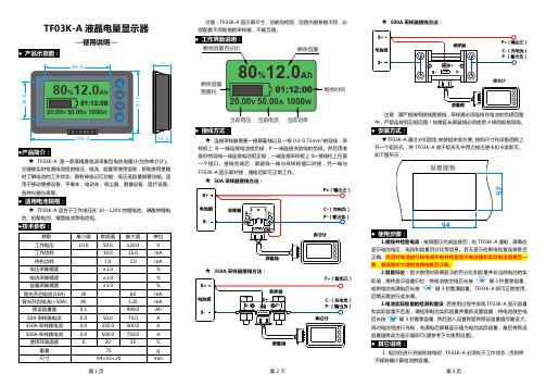
TF03K-A液晶电量显示器—使用说明—● 产品示意图:●产品简介:★ TF03K-A是一款高精度电流采集型电池电量计(也称库仑计)。
它能够实时检测电池组的电压、电流、容量等使用信息,帮助使用者随时了解电池的工作状态。
具有掉电记忆功能,低压低容量报警功能。
适用于移动便携设备、平衡车、电动车、吸尘器、测量设备、医疗设备、各种仪器仪表等。
● 适用电池规格:★ TF03K-A适合于工作电压在10~120V的锂电池、磷酸铁锂电池、铅酸电池、镍氢电池等电池组。
●技术参数:参数 最小值 常规值 最大值 单位 工作电压 10.0 50.0 120.0 V工作功耗 10.0 15.0mA 待机功耗 1.0 2.0 mA 电压采集精度 ±1.0 % 电流采集精度 ±1.0 % 容量采集精度 ±1.0 % 背光开启电流(50A) 30 60 mA 背光开启电流(>50A) 80 120 mA 预设容量值 0.1 999.0 Ah 50A采样器电流 0.0 50.0 75.0 A 350A采样器电流 0.0 350.0 500.0 A 500A采样器电流 0.0 500.0 750.0 A 使用环境温度 0 20 35 ℃ 重量 75 g尺寸 94×55×20 mm注意:TF03K-A显示屏尺寸、功能均相同,但是内部参数不同,必须配套不同规格的采样器,不能互换。
● 工作界面说明:剩余时间● 接线方式:★ 连接采样器需要一根屏蔽线以及一根0.3-0.75mm²的导线;采样板上B-一端连接电池组负极,P-一端连接充放电的负极。
然后用准备好的导线一端连接电池组正极,一端连接采样板上B+接线柱上任意一个接口。
接线完成后,屏蔽线一端与采样板插口对接,另一端与TF03K-A显示屏对接,通电后即可正常工作。
★ 50A采样器接线方法:★ 350A采样器接线方法:★ 500A采样器接线方法:注意:请严格按照接线图接线,采样器必须连接在电池的负极回路中,严禁连接到正极回路!如需延长屏蔽线必须使用4根同规格导线。
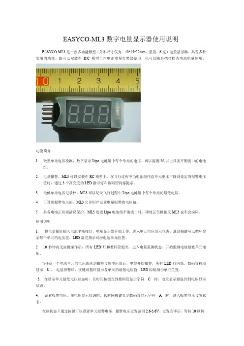
EASYCO-ML3数字电量显示器使用说明EASYCO-ML3是一款多功能微型(外形尺寸仅为:40*15*12mm,重量:6克)电量显示器。
具备多种实用的功能。
既可以安装在R/C模型上作电池电量告警器使用,也可以随身携带检查电池电量使用。
功能简介1.微型单元电压检测,数字显示Lipo电池组中每个单元的电压。
可以监测2S以上具备平衡接口的电池组。
2.电量报警。
ML3可以安装在RC模型上。
在飞行过程中当电池组任意单元电压下降到设定的报警电压值时,通过3个高亮度的LED指示灯和数码管闪烁提示。
3.最低单元电压记录仪。
ML3可以记录飞行过程中Lipo电池组中每个单元的最低电压。
4.可设置报警电压值。
ML3允许用户设置电量报警的电压值。
5.具备电池正负极插反保护。
ML3连接Lipo电池组平衡接口时,即使正负极接反ML3也不会损坏。
使用说明1.将电显插针插入电池平衡接口,电量显示器开始工作,进入单元电压显示状态。
通过按键可以循环显示每个单元的电压值。
LED常亮指示对应电池单元位置。
2.10秒钟内无按键操作后,所有LED灯和数码管熄灭,进入电量监测状态。
开始监测电池最低单元电压。
当任意一个电池单元的电压跌落到报警设置电压值后,电显开始报警,所有LED灯闪烁,数码管移动显示8。
电显报警后,按键可循环显示各单元的最低电压值,LED闪烁指示单元位置。
3.在显示单元最低电压状态时,长时间按键直到数码管显示字符C时,电量显示器返回到电压显示状态。
4.设置报警电压。
在电压显示状态时,长时间按键直到数码管显示字符A时,进入报警电压设置状态。
在该状态下通过按键可以设置单元报警电压,报警电压设置范围2.6-3.6V。
设置完毕后,等待10秒钟,电量显示器自动返回到电压监测状态。
5.测试不同单元数量电池组的连接方法。
2S电池组平衡接口EASYCO-MAL33S-6S电池组平衡接口EASYCO-MAL3Create PDF with GO2PDF for free, if you wish to remove this line, click here to buy Virtual PDF Printer。
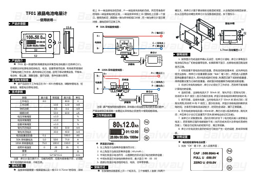
TF01液晶电池电量计—使用说明—● 产品示意图:● 产品简介:★ TF01是一款通用的高精度电流采集型电池电量计(也称库仑计)。
它能够实时检测电池组的电压、电流、容量等使用信息, 帮助使用者随时了解电池的工作状态,具有掉电记忆功能。
适用于移动便携设备、平衡车、电动车、吸尘器、测量设备、医疗设备、各种仪器仪表等。
● 适用电池规格:★ 该产品适合于工作电压在8V~80V的锂电池、磷酸铁锂电池、铅酸电池、镍氢电池等电池组。
● 技术参数:参数 最小值 常规值 最大值 单位工作电压 8.0 80.0 V工作功耗 10.0 12.0 mA待机功耗 0.5 0.6 mA睡眠功耗 50.0 60.0 uA电压采集精度 ±1.0 %电流采集精度 ±1.0 %容量采集精度 ±1.0 %背光开启电流 40.0 50.0 mA背光关闭电流 30.0 40.0 mA电池容量设定值 0.1 590.0 Ah50A采样器电流 5.0 50.0 75.0 A100A采样器电流 75.0 100.0 150.0 A使用环境温度 0 20 35 ℃ 重量 22 g尺寸 52*36*15.6 mm 注意:库仑计显示屏尺寸、功能均相同,但是内部参数不同,必须配套不同规格的采样器,不能互换。
● 接线方法:★ 连接采样器需要一根屏蔽线以及一根0.3-0.75mm²的导线;采样板上B-一端连接电池组负极,P-一端连接充放电的负极。
然后用准备好的导线一端连接电池组正极,一端连接采样板上B+接线柱上任意一个接口。
接线完成后,屏蔽线一端与采样板插口对接,另一端与库仑计显示屏对接,通电后即可正常工作。
★ 50A采样器接线图:★ 100A采样器接线图:注意:请严格按照接线图接线,采样器必须连接在电池的负极回路中,严禁连接到正极回路!如需延长采样线必须使用4根同规格导线。
● 工作界面说明:★ 界面显示说明:1. 左上角显示当前剩余容量的百分比;2. 右上角显示当前实际剩余容量(Ah/mAh);3. 中间左侧显示电池符号,以图腾柱的形式显示电池的剩余容量;4. 中间右侧显示充放电的剩余时间,最大显示99:00:005. 底部分别显示电池组的电压、电流、功率等参数。

Read OwneR's Manual caRefull y BefORe installing Bw-03. DescriptionThe BW-03 is a smart battery monitor that can measure and display the voltageof one or two battery bank(s). It can also generate an alarm for overvoltage, undervoltage and voltage differences.Features- Shallow mounting depth- Multiple battery monitoring- Open Drain alarm output- Programmable alarm thresholds- Very low power consumptionLayoutLayouts of the top and back of the unit are shown in Fig 1A & 1B, respectively.InstallationWarnings- The unit should be installed only by skilled installers / electricians who are aware of regulations for working with batteries.- Live parts must never come into contact with the housing of the BW-03.- Use of poor quality material and/or excessively low diameter cables for making the connections can damage the BW-03.- A short circuit between the Positive and Negative terminals of the battery may cause severe damage to your system.- Always use fuses (of the correct value) as shown in the connection diagrams (pages 3 & 4).Various connection configurations are shown in Figs 2 to 7. Please strictly follow the order of connections given below:Monitoring 1 Battery Bank(Figs. 3 and 4):1. Connect the Negative of the battery bank to the Minus Input T erminalmarked (MIN).2. (Optional) Connect the external alarm relay / LED from the battery Positiveto the Alarm output T erminal (OUT) - See Fig 2.3. Connect the Positive terminal of the battery to the Positive Input T erminalmarked (BAT1).Monitoring 2 Battery Banks(Figs. 5, 6 and 7):1. Connect the Negative of the 2 battery banks to the Minus Input T erminalmarked (MIN).2. (Optional) Connect the external alarm relay / LED from the battery Positiveto the Alarm output T erminal (OUT) - See Fig 2.3. Connect the Positive terminal the first battery bank (any one of the twobattery banks) to the Positive Input T erminal marked (BAT 2) .NOTE: It is important the this first connection is made on T erminal (BAT 2) and NOT on T erminal (BAT1).4. Connect the Positive T erminal of the second battery bank to the PositiveInput T erminal marked (BAT1).OperationImmediately after connection, the voltage of BAT 1 is displayed to an accuracy of one tenth of a Volt. If use is also made of the BAT 2 terminal, then the BAT 1 point (1B, Fig 1A) will flash slowly (1x per 2.5 second). This is to indicate which battery voltage is actually being displayed. When the Programming Button is pushed briefly (for less than 2 seconds), the voltage of BAT 2 appears on the display. The associated indication point, BAT 2 (1D, Fig 1A), now flashes slowly.AlarmBW-03 can generate an alarm for three different situations. These are alarms for undervoltage, overvoltage and voltage difference (programmable values are givenin T able 1). As soon as an alarm starts, the display will continuously switch between showing the alarm that has been activated (“lo”, “hi” or “diF”) and the voltage value of the selected voltage input. The buzzer and Alarm Out T erminal (OUT,Fig 1B) will also be activated.An alarm lasts for one minute, or until the Programming Button (2, Fig 1A) has been pressed for two seconds. After this, the alarm state continues in silence. This means that the buzzer and Alarm Out T erminal (OUT, Fig 1B) have now been deactivated and the display – just like normal – continuously indicates the reading from the selected battery. One of the Battery 1 (1B, Fig. 1A) or Battery 2 (1D, Fig. 1A) points will now start to flash quickly (± 2x per second) to indicate there is an alarm. In the case of a difference alarm, both points will flash quickly. The alarm is fully reset as soon as the voltage reaches a normal value once again.Power Saving ModeIf a voltage is connected to BAT 1 that results in the activation of an undervoltage alarm, the display will be switched OFF 10 minutes after the starting of the alarm. The application will continue to work in the background and if another voltage level is exceeded, the alarm will activate. In this case, the display is also (temporarily) switched ON. The display is also switched ON if the Programming Button is pushed or if the voltage of the BAT 1 input rises.As long as the voltage has not risen above the charging voltage for three days (12.8V for a 12V system and 25.6V for a 24V system), there has been no alarm and the user has also not pressed the Programming Button, then the application will reduce power consumption further by suspending all activities. Briefly pressing the Programming Button switches OFF the Power Saving Mode and the BW-03 operates normally again.ProgrammingProgramming functions are carried out with the help of the Programming / Select Button (2, Fig 1A). This button performs the following functions:1. Changing the displayed voltage.2. Resetting the alarms.3. Discontinuing Power Saving Mode.4. Configuring alarm values (see T able 1).The first three functions have been covered earlier in this manual so that only the programming of the software still remains.As soon as the Programming Button is pressed for four seconds, the display willturn OFF for a moment to indicate that the Programming Menu has been activated. Next, “lo” appears in the display, followed by the value 10.8V (21.6V), the default value – see T able 1. This means that the undervoltage alarm can be adjusted and that it is currently set to 10.8V (21.6V). This value can be changed by pressing the Programming Button. If this is done, the value will be increased by 0.1V for each press. This continues until the value of 12V is reached. If the button is pressed again, the lowest value in the table – 10.5V – is displayed. As soon as the desired value is displayed, there is a 4 second delay until “YES” is displayed. This indicates that the value chosen has been accepted.Next, the display remains blank for a moment once again followed by the text "hi". Immediately after this, a voltage value (default value of 14.8V (29.6V) - T able 1) is displayed once again. This is the overvoltage setting alarm value. This can also be adjusted by pressing the Programming Button.Differential Voltage AlarmFor a 24V system with a centre terminal (see Fig 7), there is also the additional option of activating and adjusting a differential voltage alarm. After the overvoltage, the display will turn OFF for a moment again followed by the display of “diF”.Here again, a voltage value can be selected (default is OFF “---” see T able 1). The difference from the previous two values is that now, the value displayed is in millivolts and not Volts. Another difference is that here also, the option “---” can be chosen. If this is done, the voltage differential alarm is switched OFF.BATTERY MONITOR BW-03 | OWNER'S MANuAL- Auto 12V / 24V detection- Power Saving Mode- Easy to install- Splash resistant on topAfter the last programmable value has been set, the display switches OFF for a moment once again and BW-03 functions normally again. This set value is memorised if BW-03 is (temporarily) de-energised.T able 1: Programmable Alarm SettingssPecificatiOnsParameter12V24VSupply Voltage Range 6VDC to 31VDCNominal Battery Voltage 12V / 24V , Auto SensingDisplay3 Digit, 7 Segment LED Display; Accuracy: 0.1VCurrent ConsumptionDisplay ON 20mA Display OFF 8mA Power Save Mode< 0.1mAProgrammable Voltage Settings for AlarmUnder Voltage12V (24V): 10.5V to 12.0V (21.0V to 24.0V)Default: 10.8V (21.6V)Over Voltage12V (24V): 10.5V to 12.0V (29.2V to 23.8V)Default: 14.8V (29.6V)Alarm Output Open Drain, 500 mA maximumSwitches to (-) of battery when alarm is activated Input Connections T erminal Block: Tubular Hole with set screw Connecting Wire Size / Fuse Rating AWG # 18 to 20 or 0.75mm2 / 32V . 0.5A Dimensions Height / Diameter: 60mmDepth: 20 mmDiameter of Mounting Hole: 55mmMounting Depth: 18mmWeight 200gMaterials Housing: Anodized Aluminum T op Label: Polycarbonate CertificationsCE Marked; RoHS CompliantundervoltageOvervoltage 12V24V12V24VmV110.5V 21.0V 14.6V 29.2V * - - -210.6V 21.2V 14.7V 29.4V 400 mV 310.7V 21.4V 14.8V *29.6V *450 mV 410.8V *21.6V *14.9V 29.8V 500 mV 510.9V 21.8V 15.0V 23.0V 550 mV 611.0V 22.0V 15.1V 23.2V 600 mV 711.1V 22.2V 15.2V 23.4V 650 mV 811.2V 22.4V 15.3V 23.6V 700 mV 911.3V 22.6V 15.4V23.8V750 mV 1011.4V 22.8V 800 mV1111.5V 23.0V 1211.6V 23.2V 1311.7V 23.4V 1411.8V 23.6V 1511.9V 23.8V 1612.0V24.0V*Default settings1A to 1D23Fig 1A: Layout - T op of unitLEGENDNOTE: If 2 battery banks are connected, connect to BAT2 first and then to BAT1.OUT - Drain Pin of Open Drain; Max. 500 mA BAT1 - C onnection for Positive of Battery 1BAT2 - C onnection for Positive of Battery 2MIN - Connection for Common NegativeFig 1B: Layout - Back of unitLEGEND1A 3 Digit, 7 Segment. LED Display (Steps of 0.1V)1BLED dot showing that voltage of Battery 1 is being displayed 1C LED dot showing decimal point for voltage reading1D LED dot showing that voltage of Battery 2 is being displayed 2 Select / Programming Button 3 Knurled Ring NutConnection DiagramsConnection Diagrams (continued)。


Thunderbolt 3 Dock w/ USB-C Host Compatibility - Dual 4K 60Hz DisplayPort 1.4 or Dual HDMI 2.0 Monitors - Single 8K - TB3/USB-C Laptop Docking Station - 96W PD, 5xUSB - 10GbpsProduct ID: TB3CDK2DHA high-performance Thunderbolt 3 Certified docking station with USB Type-C compatibility featuring dual monitor 4K 60Hz DSC support from either dual DisplayPort or dual HDMI 2.0 video outputs, 96W Power Delivery (100W peak power), 5x USB 3.2 Hub with 2x BC 1.2 fast charging ports, gigabit Ethernet & headset ports.This universal docking station features both dual DisplayPort 1.4 (Single 8K30 on HBR3 host) and dual HDMI video outputs that can be configured in three different ways:Resolutions and video outputs are host-dependent.Featuring an integrated USB 3.2 hub, this docking station has 5 downstream USB ports:Front Facing:• 1x USB 3.2 Gen 2 Type-C (10 Gbps) with 15W (3A, 5V) Charging• 1x USB 3.2 Gen 2 Type-A (10 Gbps) with B.C. 1.2 Fast-ChargingBack Facing:• 2x USB 3.2 Gen 1 Type-A (5 Gbps)• 1x USB 3.2 Gen 2 Type-C (10 Gbps)This universal Thunderbolt 3 / USB-C Dock has an automatic driver setup and includes a longer 0.8 meter (2.6 ft) Thunderbolt 3 host cable, front-facing TB3/USB-C host port, front-facing LED indicator, mounting holes for the optional bracket, k-slot for security lock & MAC address changer utility.The TB3CDK2DH includes a free Windows application that enables you to better manage your enterprise network security. When you connect to your network through the ethernet port of the dock, the computer's MAC address is typically not broadcast to the network, as your network only sees the MAC address of the docking station. However,the MAC Address Changer or Cloning software enables the USB-C dock to use MAC address spoofing of the connected Windows laptop rather than the MAC address of the dock itself. This ensures your network administrators have full visibility of each device on the network and can monitor and limit activity accordingly. To request access to our MAC Address Changer utility, please contact our Technical Support Department by phone, live chat, or e-mail.TB3CDK2DH is backed by a three-year warranty and free lifetime technical support. Certifications, Reports and CompatibilityApplicationsFeatures• FULL FUNCTION DOCK: Thunderbolt 3 docking station with USB-C compatibility features dual monitor 4K 60Hz, 96W PD, 5x USB Hub (incl 2x fast charge ports) with 3x USB-A (1x 10Gbps USB 3.2/3.1 Gen 2) & 2x USB-C10Gbps; Gigabit Ethernet, headset ports• 96W CERTIFIED POWER DELIVERY: Thunderbolt 3 / USB Type-C Dock can deliver up to 100W peak power (96W sustained) and charge high performance laptops, Ultrabooks & workstation laptop computers such as MacBook Pro 16, HP, Lenovo ThinkPad & Dell XPS• FLEXIBLE MONITOR OUTPUTS: Thunderbolt 3 docking station features dual DisplayPort 1.4 w/ DSC (single 8K 30Hz) or dual HDMI 2.0 video outputs w/ options for dual DP, dual HDMI or DP + HDMI displays at dual 4K 60Hz on both TB3 & USB-C (non TB3) laptops• COMPATIBILITY: Thunderbolt 3 certified dock works with both TB3 Macbooks and Windows w/ TB3 & USB-C like Dell, HP, & Lenovo; Ubuntu (18.04 & 20.04) compatible; supports extended dual displays on MacBook Pro/Air with Intel processor & single display w/ Apple M1 Chip• EASY TO USE: Universal Thunderbolt 3/USB-C dock with automatic drivers; incl. 2.6 ft (0.8m) Thunderbolt 3 host cable, mounting holes for optional bracket, k-slot for security lock & MAC address changer utilityHardwareWarranty 3 Years4K Support YesFast-Charge Port(s)YesDisplays Supported2Audio YesInterface Thunderbolt 3USB 3.2 Gen 2 - 10 Gbit/sBus Type Thunderbolt 3USB 3.2 Gen 2 10GbpsUSB-CCompatible Lock Slot Kensington Standard Slot (K-Slot)Chipset ID C-Media - CM6533Genesys Logic - GL3590Genesys Logic - GL3523Realtek - RTD2184Titan Ridge - JHL7440Cypress - CCG5CPerformanceMaximum Digital Resolutions Thunderbolt 3 Laptops Dual Monitors: 4096 x 2160 @60Hz, Thunderbolt 3 Laptops Single Monitors: 7,680 x 4,320 @30Hz, USB 3.1 Type C Laptops Dual Monitors: 4K (3840x2160) @60Hz, USB 3.1 Type C Laptops Single Monitor: 5K (5120x2880) @60Hz (DP Only)Type and Rate Thunderbolt 3 - 40 Gbit/sUSB 3.1 Gen 2 - 10 Gbit/sUSB 3.1 Gen 1 - 5 Gbit/sUSB 3.0 - 5 Gbit/sSupported ChargingOutputsBC 1.2 (1.5A)Connector(s)Internal Ports USB 3.1 USB Type C (10 pin, Gen 2, 10 Gbps)USB 3.1 USB Type-A (9 pin, Gen 2, 10 Gbps)3.5 mm AudioUSB 3.1 USB Type-A (9 pin, Gen 1, 5 Gbps)USB 3.1 USB Type C (10 pin, Gen 2, 10 Gbps)DisplayPortHDMIRJ-45Host Connectors Thunderbolt 3 USB-C (24-pin) (40Gbps)SoftwareOS Compatibility Windows 10, Windows 8, macOS Big Sur (11.0)macOS Catalina (10.15), macOS Mojave (10.14), Ubuntu (18.04 and20.04),Special Notes /RequirementsNote MacBook Air and MacBook Pro systems using the new Apple M1 chipsupport only a single external display over the Thunderbolt 3 ports,even when connected to a Thunderbolt 3 docking station with morethan one video output. This single monitor limitation does not affectIntel-based Macs with Thunderbolt 3.PowerPower Source AC Adapter IncludedPower Delivery96WInput Voltage100 - 240 ACInput Current 2.5AOutput Voltage20V DCOutput Current8.5APlug Type NEnvironmentalOperating Temperature0C to 35CStorage Temperature-20C to 70CHumidity0% to 95% (non-condensing) at 25CPhysicalCharacteristicsColor Black & Space GrayCable Length31.5 in [80 cm]Product Length 3.1 in [80.0 mm]Product Width8.7 in [22.0 cm]Product Height 1.2 in [30.0 mm]Weight of Product8.8 oz [250.0 g]PackagingInformationPackage Length 6.3 in [16.0 cm]Package Width12.0 in [30.5 cm]Package Height 4.3 in [11.0 cm]4.1 lb [1.8 kg]Shipping (Package)WeightWhat's in theBoxIncluded in Package Docking StationUniversal Power AdapterPower Cords (NA/JP, ANZ)Thunderbolt 3 Host Cable (80 cm)User Manual*Product appearance and specifications are subject to change without notice.。
显示器尺寸对应的最佳分辨率AOC V24t详细参数切换到传统表格版基本参数显示参数面板控制接口其它显示器附件保修信息基本参数•产品定位:娱乐影音•屏幕尺寸:23.6英寸•屏幕比例:16:9(宽屏)•最大分辨率:1920x1080 •最佳分辨率:1920x1080•高清标准:1080p(全高清)•面板类型:TN•背光类型:CCFL背光•动态对比度:60000:1•黑白响应时间:5ms显示参数•点距:0.2715mm•亮度:300cd/㎡•可视面积:521.28×293.22mm •可视角度:170/160°•显示颜色:16.7M•扫描频率:水平:30-80KHz 垂直:55-75Hz•带宽:148.5MHz面板控制•控制方式:按键•语言菜单:英文,德语,法语,意大利语,西班牙语,俄语,葡萄牙语,土耳其语,简体中文接口•视频接口:D-Sub(VGA),HDMI,色差,S端子,复合信号CVBS •其它接口:TV,音频输出外观设计•机身颜色:黑色烤漆,银色底座•外观设计:超薄设计,最薄处2.5cm•产品尺寸:595.4×483.54×220.13mm(包含底座)668×565×117mm(包装)•产品重量:5.5kg(净重)7.5kg(毛重)•底座功能:倾斜•音箱:内置音箱(2×2.5W)•壁挂:100×100mm其它•电视功能:支持电视功能•HDCP:支持HDCP•电源性能:90~240V交流, 50/60Hz External Adapter •消耗功率:最大:60W待机:1W•安规认证:CCC, CB, CE, GOST,EPA•其它性能:仰角:-3-10度•其它特点:Eco Mode 5种亮度情景模式获得EPEAT金奖•上市时间:2009年06月显示器附件•包装清单:显示器主机x1 底座x1电源线x1信号线x1保修卡x1电子光盘说明书x1保修信息•保修政策:全国联保,享受三包服务•质保时间:3年•质保备注:整机1月内包换,2年免费上门,3年免费全保•客服电话:400-887-8007•电话备注:8:00-22:00•详细内容:在中国大陆(不包括香港、澳门特别政区)购买并在大陆地区使用的显示器,出现保修范围内的硬件故障时,凭显示器保修证正本和购机发票到“冠捷国内维修站一览表”中的任何一个维修站均可享受1个月包换,2年在规定的城市地区免费上门维修服务,3年免费保修(包含CRT及LCD面板)的123保修服务。
Intelligent digital display instrumentAn instruction manual1. SummaryYK-11 Intelligence Measurement Controller is intelligent ,high accuracy controller for temperature, pressure or level measurement. When use it to equipped with temperature, pressure or level sensor, we can consist temperature, pressure or level measurement control system for various type and range.YK-11 Intelligence Measurement Controllers input signal can changed variously by internal relay, only 3 inputs are needed to form input signals as of thermocouple, resistance temperature detector, standard current 0~10mA or 4~20mA, 0~5V or 1~5V standard voltage.Main Feature:◆Adopt currently the most advanced A TMEL single chip microprocessor as main computer,peripheral parts are decreased benefit for high reliability◆Configure varied input type and output specifications in one instrument.◆Adopt WATCHDOG circuit, software trap and redundant, interruption power protect,digital filter technology etc.,online error correct ability is concerned so the whole computer perform high ability of anti-interference.◆Adopt double 4 digit LED displays, can display measured value and alarm setpointvalue on the same times.2.Technical specification:Measurement accuracy : 0.2%FS±1 digitResolution: 1, 0.1Display : double 4 digit LED displays.Input signal: standard current 0~10mA, 4~20mAStandard voltage: 0~5V,1~5VT hermocouple K, S, B, T, E, J, WRE, NResistance temperature Detector Pt100, Cu50, Cu100Ice point compensation error : ±1℃Alarm Output: 2-limit alarm or 4-limit alarm, every output can set as upper limit, low limit or forbidden alarm as needed.Relay contact:: AC220V/3A or AC220V/1A。
FAQ 04/2016Working with the 3SK2 diagnostic displayEasy diagnosis and transferring of safety programS i e m e n s A G 2016 A l l r i g h t s r e s e r v e dThis entry is from the Siemens Industry Online Support. The general terms of use (/terms_of_use ) apply.Security informa-tionSiemens provides products and solutions with industrial security functions that support the secure operation of plants, solutions, machines, equipment and/or networks. They are important components in a holistic industrial securityconcept. With this in mind, Siemens’ products and solutions undergo continuous development. Siemens recommends strongly that you regularly check for product updates.For the secure operation of Siemens products and solutions, it is necessary to take suitable preventive action (e.g. cell protection concept) and integrate each component into a holistic, state-of-the-art industrial security concept. Third-party products that may be in use should also be considered. For more information about industrial security, visit /industrialsecurity . To stay informed about product updates as they occur, sign up for a product-specific newsletter. For more information, visit .Table of contents1 Product overview ............................................................................................... 5 2Controlling and monitoring .............................................................................. 6 2.1 Preparation in the software .................................................................. 8 2.1.1 Filling in of project information ............................................................. 8 2.1.2 Preparation for detailed status information ........................................ 10 2.2 Displaying of plant information ........................................................... 11 2.2.1 Reading out of project information ..................................................... 11 2.2.2 Reading out of status information ...................................................... 12 2.3 Fault diagnostic .................................................................................. 14 3Transferring of projects by the help of the diagnostic display (15)3.1 Preconditions ...................................................................................... 15 3.2 Procedure ........................................................................................... 17 3.3 Use cases ........................................................................................... 20 3.3.1 Fast device exchange ........................................................................ 20 3.3.2 Fast commissioning of same application . (21)4 Contact/Support (22)S i e m e n s A G 2016 A l l r i g h t s r e s e r v e dQuestionWhich functionality can be realized by the 3SK2 diagnostic display (MLFB 3SK2611-3AA00)?S i e m e n s A G 2016 A l l r i g h t s r e s e r v e dAnswerThe diagnostic display offers easy fault location without PC/PG. It supports fast problem solution by detailed fault messages. There is no engineering in advance in the basic module necessary to connect the display. The connection outside of the control cabinet allows easy access.Furthermore with two integrated memory slots you can use the diagnostic display for saving and transferring of projects. This simplifies commissioning of identical machinery and allows quick device exchange in case of fault. It is especially helpful by use of the 22,5 mm width basic module which has no exchangeable memory module.S i e m e n s A G 2016 A l l r i g h t s r e s e r v e d1Product overviewBeside the 3SK2 diagnostic display (MLFB 3SK2611-3AA00) the 3RK3 diagnostic display (MLFB 3RK3611-3AA00) still exists. The following table shows an overview of compatibility and functionality.Table 1: Compatibility diagnostic display 3SK2 and 3RK3It is not possible to transfer projects with the 3RK3 diagnostic display.For both displays you need a connection cable, which is available in different lengths and flat and round version: MLFB 3UF793*-0*A00-0.S i e m e n s A G 2016 A l l r i g h t s r e s e r v e d2Controlling and monitoringBesides the fault detection via monitoring function within the software, the diagnostic display helps for easy problem analysis without connection of PC or PG by detailed error messages. Even in case of no failure project and status information are helpful which are available at the display.In the following image you can see a simplified menu overview of the diagnostic display.Figure 1: Menu structure diagnostic displayS i e m e n s A G 2016 A l l r i g h t s r e s e r v e dMenu items have no fixed numbering and can be hidden in the display depending on the connected device and current status. The menu items …Status Info“, …Status“ and …Configuration Transmission “ are shown in detail as they are more relevant for this FAQ.In the menu item …Status “ the state of all in- and outputs can be read out (e.g. “Switching output Switching ON Condition not satisfied ”). Comprehensive project information (e.g. Config-CRC, Project Engineer) can be found in the menu item …System Configuration “. In case of troubleshooting the menu item …Status Info “ is helpful. Here you can see detailed error messages and warnings. All status information which are available in Safety ES can be shown at the display. If no errors are present the menu item is empty.By means of an example with guard door monitoring and emergency stop theeasy diagnose in case of fault and no fault will be shown subsequently.Figure 2: Logic plan application exampleS i e m e n s A G 2016 A l l r i g h t s r e s e r v e d2.1 Preparation in the softwareThere is no previous engineering of the diagnosis display in the software necessary. The display can be plugged in without any effort in advance.For easy error tracking it is helpful to assign informative names to the function elements which will be shown in the diagnostic display. Furthermore all added project / hardware information can be read out in the display.2.1.1 Filling in of project informationIn …Identification“ and …Configuration“ information regarding project and hardware configuration can be filled in.Figure 3: Filling in of project informationS i e m e n s A G 2016 A l l r i g h t s r e s e r v e dFigure 4: Filling in of hardware informationIn the main system the diagnostic display can be added on system slot 1 optionally. This is only for documentation purpose and is not mandatory. All project information can be found in the diagnostic display in the menu item …System C onfiguration“.S i e m e n s A G 2016 A l l r i g h t s r e s e r v e d2.1.2 Preparation for detailed status informationFor easy diagnose it is advisable to name the function elements.Figure 5: Naming of function elementsBy double-clicking on the respective function element a symbolic name can be assigned in the window …properties“. T his name is displayed as further information in the diagnostic display. It is helpful to assign names for all input elements (e.g. “Emergency Stop”) as well for all output elements (e.g. “F -output”).S i e m e n s A G 2016 A l l r i g h t s r e s e r v e d2.2Displaying of plant informationTo read out information at the diagnostic display an active connection to the energised basic module must be established. There mustn’t be any additional connection from the PCs/PGs via the diagnostic display to basic module. In this case the display is locked.2.2.1Reading out of project informationInformation regarding the project or hardware can be found in the menu item …System Configuration “. In the menu item …Project“ details regarding Config- CRC, Time Stamp, Release and Project Engineer are listed. Certain information are provided automatically from the system. Other information like …Project Engineer “ are only available if the corresponding fields were filled in in thesoftware (see chapter 2.1.1 Filling in of project information).In the menu item …Slot 3“ details regarding the used basic module can be found.Table 1: Project- and HardwareinformationS i e m e n s A G 2016 A l l r i g h t s r e s e r v e d2.2.2 Reading out of status informationThe full information concerning input and output elements can be found in the menu item …Status“.The elements are displayed as follows:Figure 6: Displaying of status/status infoFor this example the guard door is opened, the Emergency Stop was pushed and released but not acknowledged yet. Thus the output is not activated. These information can be read out in …Status / Input Elements “ as well …Status / Output Elements “.E-Stop 1 (symbolic name of the element),S i e m e nsA G 2016 A l l r i g h t s r e s e r v e dProtective Door (type of function element)You can read out status information which are available as element status in the Safety ES (e.g. …Timer running “, …Wa iting for Start“).S i e m e n s A G 2016 A l l r i g h t s r e s e r v e d2.3Fault diagnosticTroubleshooting with the help of the diagnostic display will be explained by means of the application example of figure 2. There is a cross circuit between input 1 and input 2 of the emergency stop with element number 1.In case of fault detailed information can be found in the menu item “Status Info “. According to the default setting of the display the status info will be directly shown on the start screen in case of a fault (Setting adjustable in …Display Settings/ Statu s Info“)Table 2: Error messages in case of Cross-CircuitThe same procedure applies to other faults like discrepancy fault or fault within the feedback circuit. Below the element you find then the error message ‚Dis crepancy violated ‘ or ‚Feedback Circuit invalid ‘. All element messages which are available in Safety ES can be shown on the diagnostic display as well.S i e m e n s A G 2016 A l l r i g h t s r e s e r v e d3Transferring of projects by the help of the diagnostic displayThe 3SK2 diagnostic display (MLFB: 3SK2611-3AA00) has two internal memory slots at which Safety ES projects can be stored.NoteThis functionality is only available for the diagnostic display 3SK2611-3AA00. The 3RK3 diagnostic display (MLFB: 3RK3611-3AA00) has no internal memory slots and it is not possible to connect it to the 3SK2.3.1PreconditionsTo be able to transfer Safety ES projects from or to the display an activeconnection to the running basic module must be established. Furthermore it is not possible to have an additional connection from the basic module to the PG/PC via the diagnostic display. In this case the display is locked. Transferring of projects is possible with both types of 3SK2 basic modules (3SK2112, 22,5mm width/ 3SK2122, 45 mm width) as well as with the 3RK3 Advanced and 3RK3 ASIsafe.Preconditions for saving projects in the diagnostic display/ reading configurations from the deviceTo save projects within the diagnostic display 2 memory slots are available. If a project was already stored on the selected memory slot and you read out a new configuration on the same memory slot, the old one will be replaced. There are no restrictions for reading out configurations. It is possible to read out not approved and approved configurations. The device can be in configuration or safety mode. If the protection level ‚write protection‘ was selected by password for the project which will be read out from the basic module, the protection level will be copied to the configuration in the display as well.S i e m e n s A G 2016 A l l r i g h t s r e s e r v e dHinweisThe protection level ‚Read Protection ‘ should not be activated in the basicmodule (3SK“/3RK3). In this case it is not possible to read out any configuration. Thus it is not possible to copy a project with Read Protection. This can be set after download via the Safety ES Tool.Preconditions for transferring of projects to the basic module It is possible to transmit a project to the device on condition that: - Device is running in configuring mode. - No password for device access is set.- The configuration on the basic module is not approved or there is no configuration on the basic moduleIf one of these conditions is not fulfilled the download of the project fails. In case that the download fails it is possible to download the project by resetting thebasic module to factory settings via reset button (See manual 3SK2 chapter 8.1/ manual 3RK3 chapter 6.4.4.5). Afterwards the device runs up in configuring mode and the project can be downloaded.DANGERAccidentally start possibleThe operator has to ensure that the configuration is downloaded to the correct machine, otherwise it can lead to a dangerous situation.NoteThe menu …factory settings“ in the diagnostic display refers only to the diagnostic display and not to the basic module. By executing the command the configurations in the diagnostic display among others will be deleted.S i e m e n s A G 2016 A l l r i g h t s r e s e r v e d3.2 ProcedureFor reading out a configuration from the basic module an active connection to it is necessary. Downloading a project from Safety ES to the diagnostic display is not possible without the basic module.Saving a configuration in the diagnostic displaySelect the favoured Memory Slot e.g.Table 3: Backup of a projectThe project is now saved in the selected memory slot in the diagnostic display.S i e m e n s A G 2016 A l l r i g h t s r e s e r v e dThe project information of the saved project (Name, Project Engineer, Company, Config-CRC, Time Stamp, Approval, Cycle Time …) can be read out in the corresponding memory slot.Transmission of a configuration from the diagnostic display to the basic moduleTable 4 Write project to deviceThe configuration is now saved in the basic module.The project information of the downloaded project (Name, Project Engineer, Company, Config-CRC, Time Stamp, Approval, Cycle Time …) can be read out in “System Configuration/ Project”.S i e m e n s A G 2016 A l l r i g h t s r e s e r v e dNoteWhen downloading an approved configuration to the basic module the device first stays in configuring mode. To change to safety mode turn off and on the basic module. After running up, the device changes automatically to safety mode.S i e m e n s A G 2016 A l l r i g h t s r e s e r v e d3.3Use cases3.3.1 Fast device exchangeIn case of a faulty basic module the approved configuration can be transferred fast and easily to the new basic module by the help of the diagnostic display. Thus the plant operation can continue quickly.Figure 7: Fast device exchange NoteBack up the Safety ES project straight after successful commissioning of the safety application to the diagnostic display.3 Transferring of projects by the help of the diagnostic displayWorking with the 3SK2 Diagnostic displayEntry-ID: 109482844, V1.0, 04/201621S i e m e n s A G 2016 A l l r i g h t s r e s e r v e d3.3.2 Fast commissioning of same applicationBy help of the possibility to download projects from the diagnostic display the commissioning of identical machinery can be sped up. After successful function test and approving once the safety program can be downloaded to the other machinery.Figure 8: Fast commissioning of identical machinery4 Contact/SupportWorking with the 3SK2 Diagnostic displayEntry-ID: 109482844, V1.0, 04/201622Si emensA G2016Al lrigh tsr ese rv ed4 Contact/SupportSiemens AGTechnical AssistanceTel: +49 (911) 895-5900Fax : +49 (911) 895-5907Mail: ******************************** Internet: www.siemens.de/automation/support-request。
Taurus SeriesMultimedia PlayersT3 SpecificationsProduct Version: V1.3.0 Document Number:NS120100242XI 'AN NOVA ST A R TEC H C O .,L T D .Copyright © 2018 Xi’an NovaStar Tech Co., Ltd. All Rights Reserved.No part of this document may be copied, reproduced, extracted or transmitted in any form or by any means without the prior written consent of Xi’an Nova Star Tech Co., Ltd.Trademarkis a trademark of Xi’an NovaStar Tech Co., Ltd.StatementYou are welcome to use the product of Xi’an NovaStar Tech Co., Ltd. (hereinafter referred to as NovaStar). This document is intended to help you understand and use the product. For accuracy and reliability, NovaStar may make improvements and/or changes to this document at any time and without notice. If you experience any problems in use or have any suggestions, please contact us via contact info given in document. We will do our best to solve any issues, as well as evaluate and implement any suggestions.X I'A NN OV AS TA RT EC HC O.,L TD.Table of ContentsTable of Contents ............................................................................................................................ ii 1 Safety .. (1)1.1 Storage and Transport Safety ..................................................................................................................... 1 1.2 Installation and Use Safety .. (1)2 Overview (3)2.1 Introduction .................................................................................................................................................. 3 2.2 Application ................................................................................................................................................... 3 3 Features ........................................................................................................................................... 5 3.1 Synchronization mechanism for multi-screen playing ................................................................................. 5 3.2 Powerful Processing Capability ................................................................................................................... 5 3.3 Omnidirectional Control Plan .. (5)3.4 Dual-Wi-Fi Mode .......................................................................................................................................... 6 3.4.1 Wi-Fi AP Mode .......................................................................................................................................... 7 3.4.2 Wi-Fi Sta Mode .. (7)3.4.3 Wi-Fi AP+Sta Mode .................................................................................................................................. 7 3.5 Redundant Backup ...................................................................................................................................... 8 4 Hardware Structure....................................................................................................................... 9 4.1 Appearance . (9)4.2 Dimensions (11)5 Software Structure (12)5.1 System Software ........................................................................................................................................ 12 5.2 Related Configuration Software .. (12)6 Product Specifications ................................................................................................................ 13 7 Audio and Video Decoder Specifications (15)7.1 Image ......................................................................................................................................................... 15 7.1.1 Decoder .................................................................................................................................................. 15 7.1.2 Encoder .................................................................................................................................................. 15 7.2 Audio .......................................................................................................................................................... 16 7.2.1 Decoder .. (16)X I 'A N N O V A S T A R T E C H C O .,L T D.7.2.2 Encoder (16)7.3 Video (17)7.3.1 Decoder (17)7.3.2 Encoder (18)X I'A NN OV AS TA RT EC HC O.,L TD.1SafetyThis chapter illustrates Taurus series products safety to ensure storage, transportation, installation and usage safety of the products.Safety description is applicable to all personnel that contact or use the products. First, pay attention to following points:● Read throughout the description. ● Save the whole description.●Be complied with the whole description.1.1 Storage and Transport Safety ● Pay attention to dust and water prevention.● Avoid long-term direct sunlight. ● Do not place the products in the position near fire and heat.● Do not place the products in an area containing explosive materials. ● Do not place the products in strong electromagnetic environment. ● Place the products in a stable position to prevent damage or personal injury caused by dropping.●Save the packing box and materials which will come in handy if you ever have to ship your products. For maximum protection, repack your product as it wasoriginally packed at the factory.1.2 Installation and Use Safety● Only trained professionals may install the products.● Do not insert and unplug (power cord plug) when the power is on. ● Ensure the safe grounding of the device.● Be careful about electric shock risk. Built-in power supply. ● Always wear a wrist band and insulating gloves.● Do not place the products in an area having more or strong shake. ● Perform dust removing regularly.●Rather than having the product disassembled and maintained by non-certified professionals, please contact NovaStar for maintenance at any time.X I 'A N N O V A S T A R T E CHCO .,L T D.Replace faulty parts only with the spare parts supplied by NovaStar.X I'A NN OV AS TA RT EC HC O.,L TD.2Overview2.1 IntroductionTaurus series products are NovaStar's second generation of multimedia players dedicated to small and medium-sized full-color LED displays.T3 of the Taurus series products (herein after referred to as “T 3”) feature following advantages, better satisfying users’ requir ements:●Loading capacity up to 650,000 pixels●Synchronization mechanism for multi-screen playing● Powerful processing capability ● Omnidirectional control plan ● Dual-Wi-Fi mode ●Redundant backup Note: If the user has a high demand on synchronization, the time synchronization module isrecommended. For details, please consult our technical staff. In addition to solution publishing and screen control via PC, mobile phones and LAN, the omnidirectional control plan also supports remote centralized publishing and monitoring. 2.2 ApplicationTaurus series products can be widely used in LED commercial display field, such asbar screen, chain store screen, advertising machine, mirror screen, retail store screen, door head screen, on board screen and the screen requiring no PC. Classification of Taurus’ application cases is shown in Table 2-1. Table 2-1 ApplicationXI 'A N N O V A S T A R T E C H C O .,L T D.X I'A NN OV AS TA RT EC HC O.,L T3Features3.1 Synchronization mechanism for multi-screen playingThe T3 support switching on/off function of synchronous display.When synchronous display is enabled, the same content can be played on different displays synchronously if the time of different T3 units are synchronous with one another and the same solution is being played.3.2 Powerful Processing CapabilityThe T3 feature powerful hardware processing capability: ● 1.5 GHz eight-core processor●Support for H.265 4K high-definition video hardware decoding playback ● Support for 1080P video hardware decoding ● 2 GB operating memory●8 GB on-board internal storage space with 4 GB available for users 3.3 Omnidirectional Control Plan Table 3-1 Control PlanXI 'A N N O V A S T A R T E C H CO .,L T D.Cluster control plan is a new internet control plan featuring following advantages:●More efficient: Use the cloud service mode to process services through a uniformplatform. For example, VNNOX is used to edit and publish solutions, and NovaiCare is used to centrally monitor display status.● More reliable: Ensure the reliability based on active and standby disaster recovery mechanism and data backup mechanism of the server. ● More safe: Ensure the system safety through channel encryption, data fingerprintand permission management. ● Easier to use: VNNOX and NovaiCare can be accessed through Web. As long asthere is internet, operation can be performed anytime and anywhere. ●More effective: This mode is more suitable for the commercial mode of advertising industry and digital signage industry, and makes information spreading more effective. 3.4 Dual-Wi-Fi Mode The T3 have permanent Wi-Fi AP and support the Wi-Fi Sta mode, carryingadvantages as shown below:●Completely cover Wi-Fi connection scene. The T3 can be connected to through self-carried Wi-Fi AP or the external router.●Completely cover client terminals. Mobile phone, Pad and PC can be used to log in T3 through wireless network.●Require no wiring. Display management can be managed at any time, having improvements in efficiency.T3’s Wi -Fi AP signal strength is related to the transmit distance and environment. Users can change the Wi-Fi antenna as required.XI 'A NN O V A S T A R T E C H C O .,L T D3.4.1 Wi-Fi AP ModeUsers connect the Wi-Fi AP of a T3 to directly access the T3. The SSID is “AP + the last 8 digits of the SN ”, for example, “AP10000033”, and the default password is “12345678”.3.4.2 Wi-Fi Sta Mode Configure an external router for a T3 and users can access the T3 by connecting the external router. If an external router is configured for multiple T3 units, a LAN can becreated. Users can access any of the T3 via the LAN.3.4.3 Wi-Fi AP+Sta ModeIn Wi-Fi AP+ Sta connection mode, users can either directly access the T3 or accessinternet through bridging connection. Upon the cluster solution, VNNOX andNovaiCare can realize remote solution publishing and remote monitoring respectively through the Internet.XI 'A N N O V A S T A R T E C HCO .,L T D.3.5 Redundant BackupT3 support network redundant backup and Ethernet port redundant backup.●Network redundant backup: The T3 automatically selects internet connectionmode among wired network or Wi-Fi Sta network according to the priority.●Ethernet port redundant backup: The T3 enhances connection reliability throughactive and standby redundant mechanism for the Ethernet port used to connectwith the receiving card.X I'A NN OV AS TA RT EC HC O.,L TD.4Hardware Structure4.1 AppearanceFigure 4-1 Appearance of T3Note: Product images provided in this file are for reference only, and the actualproducts shall prevail.Table 4-1 Connectors and buttons of the T3XI 'AN NOVA S TAR T E C HCO .,L T D.Note: Product images provided in this file are for reference only, and the actual products shall prevail.Table 4-2 Indicators of the T3 A R T E C HCO .,L T D.4.2 DimensionsThe total thickness (board thickness + thickness of the components on the front andback side) is no greater than 25.0mm.Unit of the dimension chart is “mm”. Ground connection is enabled for location hole(GND).X I'A NN OV AS TA RT EC HC O.,L TD.5Software Structure5.1 System Software● Android operating system software ● Android terminal application software ●FPGA programNote: The third-party applications are not supported.5.2 Related Configuration SoftwareTable 5-1 Related configuration softwareE C HCO .,L T D.6 Product Specifications SpecificationsAntennaAntenna extension mastX I'A NN OV AS TA RT EC HC O.,L TD.7Audio and Video DecoderSpecifications7.1 Image7.1.1 Decoder7.1.2 EncoderO .,L T D.7.2 Audio 7.2.1 Decoder7.2.2 Encoder7.3 Video 7.3.1 DecoderNote: Output data format is YUV420 semi-planar, and YUV400(monochrome) is also supported for H.264.7.3.2 EncoderXI 'AN NOVA S。
TF03K-B液晶电量显示器—使用说明—●产品示意图:●产品简介:★ TF03K-B是一款高精度电流采集型电池电量计(也称库仑计)。
它能够实时检测电池组的电压、电流、容量等使用信息,帮助使用者随时了解电池的工作状态。
具有掉电记忆功能,低压低容量报警功能。
适用于移动便携设备、平衡车、电动车、吸尘器、测量设备、医疗设备、各种仪器仪表等。
● 适用电池规格:★ TF03K-B适合于工作电压在10~120V的锂电池、磷酸铁锂电池、铅酸电池、镍氢电池等电池组。
●技术参数:参数 最小值 常规值 最大值 单位 工作电压 10.0 50.0 120.0 V工作功耗 10.0 15.0 mA待机功耗 1.0 2.0mA 电压采集精度 ±1.0 % 电流采集精度 ±1.0 % 容量采集精度 ±1.0 % 背光开启电流(50A) 30 60 mA 背光开启电流(>50A) 80 120 mA 预设容量值 0.1 999.0 Ah 50A采样器电流 0.0 50.0 75.0 A 350A采样器电流 0.0 350.0 500.0 A 500A采样器电流 0.0 500.0 750.0 A 使用环境温度 0 20 35 ℃ 重量 75 g尺寸 94×55×20 mm注意:TF03K-B显示屏尺寸、功能均相同,但是内部参数不同,必须配套不同规格的采样器,不能互换。
● 工作界面说明:剩余时间电池● 接线方式:★ 连接采样器需要一根屏蔽线以及一根0.3-0.75mm²的导线;采样板上B-一端连接电池组负极,P-一端连接充放电的负极。
然后用准备好的导线一端连接电池组正极,一端连接采样板上B+接线柱上任意一个接口。
接线完成后,屏蔽线一端与采样板插口对接,另一端与TF03K-B显示屏对接,通电后即可正常工作。
★ 50A采样器接线方法:★ 350A采样器接线方法:★ 500A采样器接线方法:注意:请严格按照接线图接线,采样器必须连接在电池的负极回路中,严禁连接到正极回路!如需延长屏蔽线必须使用4根同规格导线。
● 安装方式:★TF03K-B通过卡扣固定,安装起来很方便。
按照尺寸在设备面板上开一个矩形孔,将TF03K-B放于矩形孔中用力按压使卡扣卡紧即可。
1.接线并检查电流:按照图示完成连接后,给TF03K-B通电,屏幕应显示电池电压,电流和容量百分比等信息。
若无显示应断电检查连接是否正确。
然后对电池进行放电或充电并检查显示电流值和实际电流值是否一致,若误差较大请检查接线是否正确。
2.容量归位:3秒置零容量,3秒置满容量。
TF03K-B即可正常使用,后期无需进行此步骤。
3.电池实际容量的检测和重设:若使用过程中发现TF03K-B显示容量后长按键3秒置零容量,然后进入设置界面将预设容量值尽量设大。
再对电池组进行充电,充满电后屏幕显示值为电池实际容量,最后将预设容量值修改为显示值即可(请参考下文使用设置)。
● 其它说明:1. 电池在进行充电和放电时,TF03K-B必须处于工作状态,否则将不能准确计算电池的容量。
2. 连接负载,当放电电流大于背光开启电流时,背光亮起(若背光闪烁,则说明B-和P-接反),指示电池在放电,并显示放电电流,电压和剩余时间。
若负载电流波动较大,时间也会波动,属于正常现象。
3. 断开负载,连接充电器,当充电电流大于背光开启电流时,背光闪烁(若背光常亮,则说明B-和P-接反),指示电池在充电,并显示充电电流,电压和剩余时间。
4. 当充电或放电电流小于背光关闭电流时,TF03K-B 背光熄灭进入低功耗状态,按下任一按键背光开启10S。
5. TF03K-B 灵敏度较高,因此在待机状态下(电池组无输入或者输出电流),若受到附近强烈电磁辐射干扰(如开启或关闭大功率电机等感性负载),可能会引起背光的短暂开启,属正常现象。
6. TF03K-B 在电流变化剧烈的场合可能会产生一定的误差,影响采样精度。
● 使用设置:★1.3秒,进入设置菜单。
2. CAP—预设容量:出厂时为初始容量,请根据电池组实际容量设置; HIGH U—满容量电压:高于此电压值容量自动置为100%; LOW U—零容量电压:低于此电压值容量自动置为0%,若继续放电则电压值闪烁,蜂鸣器10s 报警一次;Alarm—低容量报警:低于此容量时,百分比和电池池闪烁,蜂鸣器10s 报警一次。
注意:一般无需设置HIGH U 和LOW U,默认为0V,即无效状态。
选择4. 完成所有项目设置并确认无误后★电池置零容量与置满容量操作:在主界3秒进行零容量操作,容量百分比0%;长按3秒进行满容量操作,容量百分比100%。
注意以上操作具有不可恢复性,请谨慎使用。
★ 睡眠状态的开启与唤醒:1. 当电池电流较小时,TF03K-B 将进入极低功耗的睡眠状态。
此时可按任意按键查看电量等信息,TF03K-B 唤醒并显示5秒;如果电流未升到正常值,将再次进入睡眠状态。
当电流上升至正常值后或进入充放电状态后,TF03K-B 自动唤醒。
2. TF03K-B 可以长期连接在电池组上而不必增加开关。
● 通讯功能:TF03K-B 可定制串口通讯功能,传送电池的电压,容量,如容量百分比等信息。
通讯波特率采用9600Kbps,工作时每秒发送一次,每次发送16字节数据,接口电平为3-5V TTL,内部采用安全可靠的光耦隔离方式。
详细说明见《TF03库仑计TTL 串口通讯协议》。
● 输出控制功能:TF03K-B 可定制输出控制功能。
可外界扩展继电器、大功率报警器等,低电压或低容量时输出导通。
采用光耦隔离方式。
输出耐压60V,最大允许电流0.5A。
详细说明见《TF03库仑计输出功能说明》。
● 注意事项及质保:★ TF03K-B不能在阳光下长期暴晒,也不能长时间暴露在低于-20℃和高于60℃的极端条件下,否则将缩短液晶屏的使用寿命。
★ 本产品自购买日起一年内为质保期,在此段时间内产品若出现非人为质量问题,均可免费维修。
本产品可能会技术改进或更新,如果您购买的产品与《产品使用说明书》中所描述的产品外观、技术参数等有出入,请以实物或网站介绍为准。
TF03K-B Battery Capacity T ester—Instruction—● Sketch:●Overviews:★ TF03K-B is a kind of high precision current type battery capacity tester (also known as coulometer),which can test the voltage,current and capacity of battery to help users know the state of battery in time. TF03 have memory function,low voltage and capacity alarm function. It is suitable for mobile and portable equipments、e-bike、balance cars、cleaning machines、instruments、ups and so on.● Application:★ TF03K-B is suitable for lithium batteries,lithium iron phosphate batteries,lead-acid batteries and nickel-metal hydride batteries which voltage is from 10V to 120V.● Basic parameters:Parameter Min Type Max Unit Working Voltage 10.0 50.0 120.0 VWorking dissipation 10.0 15.0 mAStandby dissipation 1.0 2.0 mAVoltage accuracy ±1.0 %Current accuracy ±1.0 %Capacity accuracy ±1.0% Backlight on current(50A) 30 60 mA Backlight on current(>50A) 80 120 mA Preset capacity value 0.1 999.0 Ah Current of 50A sampler 0.0 50.0 75.0 A Current of 350A sampler 0.0 350.0 500.0 A Current of 500A sampler 0.0 500.0 750.0 ATemperature range 0 20 35 ℃Weight 75 gSize 94×55×20 mmNote: The size and function of TF03K-B are the same, but theinternal parameters are different, so it must match correctsampler, and cannot exchange.● Interface description:CapacityResidualvoltage current powerpoolCharge discharge-● Connect:★ We need a shielded wire and a ordinary wire (0.3-0.75mm²).One end of the ordinary wire connects to positive,anotherend connects to B+ of sampler (any one is ok). The B- of samplerconnects to B- of battery. P- of sampler connect to P- of output.Finally connect sampler to TF03K-B by the shielded wire.★ Connection diagram of 50A sampler:★Connection diagram of 350A sampler:★Connection method of 500A sampler:Attention: Please connect as shown strictly. The samplermust be connected to the negative circuit,it is forbidden toconnect to the positive circuit. If you want to extend the shieldedwire,you must use 4 lines of same specification.● Install:★ TF03K-B is fixed by buckles, so it is easy to install. First,open one rectangular orifice on the panel according to the size.Then put TF03K-B into the rectangular orifice, and make sure thebuckles are locked.1. Connect and check the current:Power on after completethe connection as shown,the screen should display capacitypercentage. If the screen has no response,please check theconnection. Then charge or discharge the battery, and checkwhether the display current is equal to the actual current. Ifthe deviation is large please check the connection.2.Capacity reset:On first use,the percentage and capacity isnot the actual value,discharge thezero or charge the battery fully and hold the key for 3s to setthe capacity full. TF03K-B will be work,and it doesn't need to dothis again later, except replace the battery.3.Check and reset the actual capacity:If you find the displaycapacity don't match the actual capacity during use,pleasecheck and reset the actual capacity:discharge the battery totallyand hold thekey for 3s to set the capacity zero,then set thepreset capacity as large as possible. Then charge the battery fully,and the display capacity is the actual capacity. Finally set the display capacity as preset capacity (Please refer to use setting).●Other description:1. When charging or discharging,TF03K-B must be at work. Otherwise the capacity will not be accurate.2. Connect the load,when the discharge current is higher than backlight on current,backlight on (if backlight blinking,the B- and P- are inversely) indicate battery is discharging. Besides,display the discharge current and remaining time. Note that the time will fluctuate if the current fluctuate greatly.3. Break the load,and connect the charger. When the charge current is higher than backlight on current,backlight blinking (if backlight on,the B- and P- are inversely) indicate battery is charging. Besides,display the charge current and remaining time.4. When the charge or discharge current is less than backlight off current, TF03K-B enter a low power state and backlight off. But TF03K-B can remember the capacity .Click any one of the keys,backlight on 10s.5. Because of high sensitivity,when TF03K-B in standby mode (battery has no input or output current),if it is interfered by electromagnetic radiation (open or close inductive loads,such as high-power motor) nearly,the backlight will shortly turn on.6. When the current changes frequently the date acquisition may produce error,and it will affect the accuracy.● Use setting:★ Preset2. ClickCAP—preset capacity:an initial capacity has been set at factory, please set it according to the real capacity;HIGH U—full voltage:when the voltage is higher than it thepercentage will be 100%;LOW U—zero voltage:when the voltage is lower than it thepercentage will be 0%. If you keep discharge the voltage valueflicker and buzzer warning once every 10s;Alarm—alarm setting:when the capacity is lower than it,percentage and capacity pool flicker and buzzer warning onceevery 10s;.Note:Generally the HIGH U and LOW U do not need to set.The default is 0V,which is the invalid. If you want set,pleaseunderstand the actual charge and discharge voltage of batteryfirstly.3.Select“CAP”and clickthe presetother bits,orkey to plus and minus the value;4. We can set other items with the same method as presetcapacity. Whenitems are set andall the values aremenu;★ Set capacity zero or full:When on first use or change the battery,the memoryhold theis 100. Attention that the operations can not be restored.★ Sleep mode wake up operation:1. When the battery current is less, TF03K-B enter a extremelow power sleep mode. Press any key can see the display ifneeded,TF03K-B woken up and displays 10s. If the batterycurrent not rise to normal value,TF03K-B will enter sleep modeagain. When the battery current rises over normal value or thebattery start charging or discharging,TF03K-B will wake up.2. TF03K-B can connect to the battery pack without anadditional switch for a long time.●Communication function:TF03K-B has serial communication function,please check the《TF03 TTL serial communication function》for details.●Control function:TF03K-B has output control function,please check the《TF03output control function》for details.● Attention and warranty:★TF03K-B cannot be exposed in the sun for a long time orin the environment with large amounts of ultraviolet radiationwhen using or storing,particular in winter (<-20℃) and summer(>60℃),otherwise it will shorten the life of LCD.★ Within one year,any fault caused by non-artificial reasonwe should maintain it freely.Our products will keep upgrading,if the product you bought is different with thisinstruction,please take the material object or website as the standard.。