API 20NE (20050)中文说明书
- 格式:pdf
- 大小:265.33 KB
- 文档页数:5


REX-P200 =中文簡易操作說明書=
1.設定流程圖: ( □:表示按PARA鍵)
2.功能流程圖: ( □:表示按PARA鍵)
3.參數設定說明: (1)各參數群說明:
☆注意: (1)當按PARA時,各參數由上往下逐一顯示,但若隱藏鍵和PARA鍵一起按時,則各參數由下往上顯示之.
注意: (2)各項顯示若超過30秒不操作,則隨即回到程式控制監視顯示.
注意: (3)按鍵操作除用手指以外,請勿使用其他物件.
4.控制動作說明:
(1)功能循環圖:
隱藏鍵+ MAN鍵
隱藏鍵+RUN鍵
(2)顯示幕模式:
(空白)
(3)初期功能狀態:
1.準備動作:將主機抽出與外殼分離,然後找出內部開關A,將開關板到on的位置,接著再
將主機插回.
2.初期功能狀態說明表:
5.主要功能說明:
(1)顯示幕:
(2)Err訊息:
(3)故障發生時的輸出動作情形:
a.繼電器接點,SSR接點,Triac接點,警報接點:OFF.
b.電流接點,連續電壓接點,類比訊號輸出接點:-5%或更少.
c.FAIL接點:接點打開.
d.
(1)如圖示同時按隱藏鍵加SV左邊的空白區,則螢幕出現2~3秒的閃爍.”LoCL SET”字樣,此
時即表示資料已鎖定完畢.
(2)若再按一次隱藏鍵加SV左邊的空白區,則螢幕會出現2~3秒的閃爍”LoCK CLr”字樣,此
時即表示資料以解除鎖定.。

智能电容状态显示器使用说明书苏州士林电机有限公司版本号:SC07_V18.12.6目录一.产品概述 (1)二.功能特点 (1)三.使用环境 (1)四.技术参数 (1)五.机械安装 (2)六.电气接线 (2)七.面板说明 (2)八.调试与运行 (4)1.工作指示灯 (4)2.闭锁指示灯 (4)3.通讯指示灯 (4)4.分补、共补指示灯 (4)九.售后服务 (5)1.质保期 (5)2.技术支持 (5)一.产品概述本产品为我公司最新研制,与本公司智能低压电力电容器配套使用,代替传统的电容指示灯和功率因数表。
该产品集成化程度高,外形美观大方,通用仪表尺寸,安装方便,接线简单,能大大提高整柜生产效率,整体提升产品质量。
二.功能特点1、混补显示面板上集成70只高亮LED指示灯,最多可同时指示20只共补电容和10只分补电容状态,共补显示器显示面板上集成70只高亮LED指示灯,最多可指示32只共补电容状态;LED指示灯功耗小,亮度高。
2、采用数字通讯方式,与智能低压电力电容器交换信息,自动采集系统功率因数和电容状态信号,并快速刷新显示。
3、自带通讯故障检测,当通讯总线故障或无通讯时,数码管熄灭需要检查通讯。
三.使用环境海拔高度≤3000m,湿度≤90%(20℃),环境温度为-20℃-60℃,大气压力为79.5-106.5kpa,无易燃易爆的介质存在,无导电尘埃及腐蚀性气体存在。
四.技术参数额定电压:交流50Hz,380V±20%额定功耗:不大于3VA五.机械安装在屏柜上开113*113mm的方孔,将本产品从屏前推入方孔内,把配给的塑料紧固件插入安装槽中,上紧即可固定在屏上。
六.电气接线电气接线按下图输出端子定义准确接线(共补混补接线方式相同)。
状态显示器接线端子图图中,电源接入380V电压,其波动应在允许范围内;电容显示器与智能低压电力电容器之间的通讯总线连接采用产品配套的数据线直接插拔连接。
七.面板说明1、混补显示器面板说明:2、共补显示器面板说明:八.调试与运行检查接线,确认无误后,接通电源,数码管显示“PF”,5秒后,数码管轮流显示各相位的功率因数,电容状态显示器即工作于自动状态。

20/20MPIMain Features• Long distance Flame Detection (up to 140ft / 43m)• Large Field of View (100° horizontal / 90° vertical)• Highest immunity to false alarms• Output options (two models):– Alarm and Fault relay outputs (4 wire)or– Stepped mA output (3 wire source)• RS-485 Modbus Compatible• Automatic and Manual Built-In-Test (BIT)• 3 Year WarrantyWith its lightweight housing and low power consumption,the 20/20MPI provides a cost effective solution, speciallysuited to indoor applications such as transport terminals,storage areas, industrial kitchens and historical andcultural sites with large open areas, providing an efficientalternative smoke and heat detectors often prove to beineffective.The 20/20MPI is a compact, lightweight, high performanceIR3 detector with a new design for retail use based onindustrially proven IR3 technology. The 20/20MPI retainsall the benefits of IR3 technology, including long distancedetection and the highest immunity to false alarms.A compact,lig h tweig h t,high performanceIR3 Flame Detectorbased on Spectrex’s proven industrialIR3 technologyAIRPORT TERMINALSAirport terminals situated in dense cities often have large halls, accompanied by retail, food and beverage outlets, each with their fire risks, which don’t have full fire protection coverage. With the structure’s size and complex design, fires are often difficult to detect and larger fires are less common due to the large air intake.TRAIN STATIONS AND TERMINALSTrain stations and terminals often have large atria containing food and beverage outlets which have large air intake and often have little fire protection coverage. Additionally, within these areas, electricity and fuel are present, increasing the chances of ignition.STORAGE AREASA wide range of substances are stored within open or closed storage facilities, part of which can be dangerous or flammable, creating a greater fire hazard than usual.ARCHIVESA large amount of paper work collecting dust poses potential fire hazards that require monitoring.MALLSWith over 1,000 fire events taking place annually within the retail industry, it is imperative that the large open areas with high ceilings found in shopping malls have full fire protection coverage in order to avoid damage to assets and personnel.HOSPITALSHospitals consist of large open spaces and confined rooms, all of which contain a wide variety of contents that pose hazards. Cooking and heating equipment, as well as electrical distribution, lighting and medical equipment such as oxygen tanks are found throughout hospital buildings and are all potential fire risks which should be protected against.Main ApplicationsCAR PARKING TOWERS AND GARAGES Areas intended for vehicle storage or maintenance contain large amounts of fuel and fumes within an enclosed space, posing a fire hazard that must be monitored.PUBLIC BUILDINGSPublic buildings often house governmental offices and more, requiring excellent fire protection in order to prevent damage to assets and personnel in any potential fire.BANKS AND OFFICESBanks and offices face common fire hazards with large open areas, coupled with large amounts of paperwork and a large volume of people constantly passing through.HISTORICAL AND CULTURAL SITES Historical, cultural or national sites often contain irreplaceable assets, alongside flammable materials. A fire within these areas which were not designed with safety in mind would cause irreversible damage. AIRCRAFT HANGARSLarge open floor areas with high roofs provide a suitable area for aircraft storage and repair. However, the large quantities of liquid jet fuel and risk of spill, coupled with maintenance activities provide potential ignition sources which is complicated by aircraft wing obstructions. CABLE TUNNELSCable tunnels play an essential role in every industrial company. Any fire damage to the cables puts entire production areas out of action. As the cable tunnel environment deteriorates with time, cable insulation performance decreases, leaving an increased heating value and greater risk of tunnel fires and detection of these fires is essential in order to prevent further damage.Main ApplicationsGENERAL SPECIFICATIONSSpectral Response Three IR Bands ft m ft mDetection Range n-Heptane 140 43 Methanol 100 30*Highest sensitivity setting Gasoline 140 43 IPA (Isopropyl Alcohol) 115 35for 1 ft2 (0.1m2) pan fire Diesel Fuel 100 30 Methane* 40 12JP5 100 30 LPG (Propane)* 40 12Kerosene 100 30 Polypropylene Pellets 50 15Alcohol (Ethanol) 100 30 Office Paper 50 15*20" (0.5m) long 8" (0.2m) width plume fireResponse Time Typically 5 secondsAdjustable Time Delay Up to 30 secondsSensitivity Range 4 sensitivity ranges for 1 ft2 (0.1m2) gasoline pan fire: 35 ft (11m) up to 140 ft (43m) Field of View100° horizontal, 90° verticalBuilt-in-Test Manual and Automatic BITTemperature Range Operating: -40°F (-40°C) to +160°F (+70°C)Storage: -40°F (-40°C) to +160°F (+70°C)Humidity Up to 95%ELECTRICAL SPECIFICATIONSPower Supply Operating Voltage: 18-32 VDCPower Consumption20/20MPI-R at 24V DC: Max. 15mA at NormalMax. 25mA at Alarm20/20MPI-M at 24V DC: Max. 16mA at NormalMax. 36mA at AlarmElectrical Connection M20 Gland ConnectionElectrical Input Protection Per EN54-10Electromagnetic Compatibility EMI/RFI protected CE Marked per EN50130-4OUTPUTS20/20MPI-R Relays Alarm and FaultSPST volt-free contacts rated 2A at 30 VDC Fault relay normally closed,Alarm Relay normally open20/20MPI-M 0-20mA Source configurationFault: 0 +0.5mA Warning: 16mA ±5%BIT Fault: 2mA ±10% Alarm: 20mA ±5%Normal: 4mA ±10% Resistance Loop: 100-600 ΩMECHANICAL SPECIFICATIONSDimensions 4.7" dia x 2.9" (119mm x 74mm)Weight10.6 oz (300g)Tilt Mount Weight 2.5 oz (70g)Enclosure and Tilt Mount PolycarbonateWater and Dust I P55PERFORMANCE APPROVALSFM3260 ApprovedEN54-10 (VdS) ApprovedACCESSORIESTilt Mount 768004 (included with each new detector)Protective Cover 768005 (included with each new detector)Flame Simulator FS-1100Specifications subject to changeFor more information view manual or website DS-F-20/20MPI, April 2017。


华光A120单盘光端机安装、使用手册潍坊北大青鸟华光通信技术有限公司版权声明本产品的所有部分,包括配件等,其所有权归潍坊北大青鸟华光通信技术有限公司(以下简称华光)所有。
未经华光公司书面许可,不得任意仿制、拷贝、誊抄或转译。
除此之外,本使用手册所提到的产品规格和资讯仅供参考,内容亦会随时更新,恕不另行通知。
有关信息请向华光公司咨询。
版权所有 不得翻印 潍坊北大青鸟华光通信技术有限公司产品名称:A120 单盘光端机手册版本:2.1发表日期:2002年1月第1次印刷:2002年 4 月注:直至付印,本手册内容力求与产品细节相符合。
但公司本着技术不断进步的原则,保留随时修改设计的权力,恕不另文通告。
潍坊北大青鸟华光通信技术有限公司的联络资讯WEIFANG BEIDA JADE BIRD HUAGUANG COMMUNICA TION TECHNOLOGY CO.,LTD地址:潍坊市高新技术开发区北宫东街6号 (261061)电话:(0536)2991022, (0536)2991031,传真:(0536)2991025网址: 目录1. 概述 (1)2. 系统构成 (2)2.1. 原理框图 (2)2.2. 功能单元介绍 (2)2.3. 面板安排 (3)2.4. 信号接口 (3)3. 安装 (5)3.1. 机械安装 (5)3.2. 电气安装 (6)3.2.1. 电源连接 (6)3.2.2. 基群2M信号连接 (6)3.2.3. 光缆连接 (6)3.2.4. 公务电话 (6)3.2.5. 告警电缆 (7)3.2.6. 监控电缆连接 (7)3.2.7. 辅助数据信道连接 (7)4. 使用与维护 (7)4.1. 开机与测试 (7)4.2. 监控软件 (8)4.3. 指示灯说明 (10)5. 性能指标 (11)5.1. 系统参数 (11)5.2. 光接口指标 (11)5.3. 2M接口电气特性 (11)5.4. 监控接口 (12)5.5. 数据通道 (12)5.6. 告警接口 (12)5.7. 系统供电 (12)5.8. 工作环境 (13)5.9. 机箱尺寸 (13)6. 附录:A120 V.35接口使用说明 (13)潍坊北大青鸟华光通信技术有限公司A120 单盘光端机安装、使用手册1.概述潍坊北大青鸟华光通信技术有限公司研制的A120型光电一体跳群光纤传输设备基本传输结构为点对点型,亦可以背靠背方式组成各种复杂网络,提供4条E1(2048kbps)准同步透明数字信道。

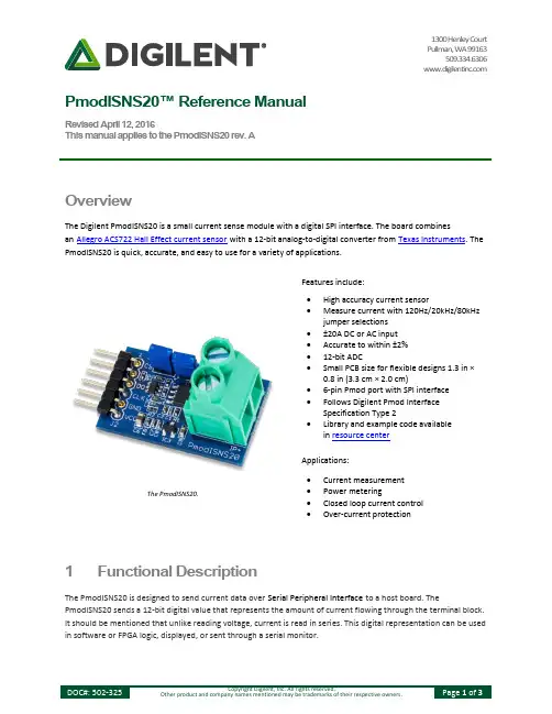
1300 Henley Court Pullman, WA 99163509.334.6306 PmodISNS20™ Reference ManualRevised April 12, 2016This manual applies to the PmodISNS20 rev. AOverview1 Functional DescriptionThe PmodISNS20 is designed to send current data over Serial Peripheral Interface to a host board. ThePmodISNS20 sends a 12-bit digital value that represents the amount of current flowing through the terminal block. It should be mentioned that unlike reading voltage, current is read in series. This digital representation can be used in software or FPGA logic, displayed, or sent through a serial monitor.The PmodISNS20.∙ High accuracy current sensor∙ Measure current with 120Hz/20kHz/80kHzjumper selections ∙ ±20A DC or AC input ∙ Accurate to within ±2% ∙ 12-bit ADC∙ Small PCB size for flexible designs 1.3 in ×0.8 in (3.3 cm × 2.0 cm)∙ 6-pin Pmod port with SPI interface ∙ Follows Digilent Pmod InterfaceSpecification Type 2∙ Library and example code availablein resource center∙ Current measurement∙ Power metering∙ Closed loop current control ∙ Over-current protectionFeatures include:Applications:2 Interfacing with the PmodThe PmodISNS20 communicates with the host board via the SPI protocol. The 12 bits of digital data are sent to the system board in 16 clock cycles with the most significant bit first. For the ADC7476, each bit is shifted out on each falling edge of the serial clock line after the chip select line is brought low with the first four bits as leading zeroes and the remaining 12 bits representing the 12 bits of data. The datasheet for the ADC7476 recommends that for faster microcontrollers or DSPs, the serial clock line is first brought to a high state before being brought low after the fall of the chip select line to ensure that the first bit is valid.Header J1Pin Signal Description1 CS Chip Select2 (NC) Not Connected3 MISO Master-In-Slave-Out4 CLK Serial Clock5 GND Power Supply Ground6 VCC Positive Power Supply (3.3V)Table 1. Pinout description table.Figure 1. PmodISNS20 timing diagram.The PmodISNS20 uses three wires to communicate with the host board. The wires used are Chip Select (CS), Serial Clock (CLK), and Data Out (DO) – also known as MISO. At 0.0 Amps, the ADC will return over SPI a value of 2048. At full negative current, a value of 0 will be returned, and likewise at full positive current a value of 4095 will be returned. Knowing this we can derive the equation needed in order to convert this signal into useful information.I mA=100089.95(ADC VALUE−2048)The scaling value at the beginning of the equation was derived using the provided sensitivity of 66mV/A off of the ACS722 datasheet. Note that the provided sensitivity is based on a reference voltage of 3.3V to the sensor and our design provides a regulated 3.0V for a cleaner signal, so some more correction may be needed if absolute accuracy is needed.Table 2 below shows how to configure the sampling rate frequency. The current sensing chip allows either 20 kHz or 80 kHz sampling rate which is configured with Jumper 2. Enabling Jumper 1 turns on an analog filter to bring it down to 120 Hz. The lower frequency is useful to keep noise down on <120 Hz AC circuit applications, such as reading from mains power.Rate JP1 JP2120 Hz Enabled Enabled120 Hz Enabled Disabled20 kHz Disabled Enabled80 kHz Disabled DisabledTable 2. Sample rate frequency configuration.In order to read the amperage flowing through the ISNS20, the power source will need to be wired in series through the green terminal block, noting proper polarity indicated by the silkscreen on the PCB. When using the ISNS20 for measuring Alternating Current (such as from mains), absolute care should be taken. Improper use of the ISNS20 on mains power can result in fire, injury, and even death – extreme caution should be taken.Any external power applied to the PmodISNS20 must be within 3.0V and 3.6V; however, it is recommended that Pmod is operated at 3.3V.3 Physical DimensionsThe pins on the pin header are spaced 100 mil apart. The PCB is 1.3 inches long on the sides parallel to the pins on the pin header and 0.8 inches long on the sides perpendicular to the pin header.。

NE20E-S16 Configuration Help1. New site or ExpansionThis parameter is used for the NE20E-S to choose to purchase a new chassis or the old chassis only expand LPU or upgrade software. If you want to purchase a newNE20E-S , select "New site".If the software upgrade of the different version or the old chassis only expand LPU, select "Expansion".2. Please select the versionV800R008 supports the following:Hardware:Replacement of old hard pipe cards with the 2-Port 10GBase LAN/WAN-SFP+Physical Interface Card H and 8-Port 100/1000Base-X-SFP Physical Interface CardHPlease confirm the corresponding iManager version is correct when you select theversion:V800R005:the corresponding iManager U2000 version is V100R009C00 or later;V800R006:the corresponding iManager U2000 version is V200R014C50 or later;V800R007: the corresponding iManager U2000 version is V200R015C50 or later;eSight version is V300R003C10 or later;V800R008: the corresponding iManager U2000 version is V200R016C50 or later;eSight version is V300R006C00 or later;V800R009: the corresponding iManager U2000 version is V200R017C50 or later;V800R010: the corresponding iManager U2000 version is V200R018C50 or later.V800R011: the corresponding iManager U2000 version is V200R018C60 or later.3. Please select the version that after upgradingV800R008 supports the following:Hardware:Replacement of old hard pipe cards with the 2-Port 10GBase LAN/WAN-SFP+Physical Interface Card H and 8-Port 100/1000Base-X-SFP Physical Interface CardHPlease confirm the corresponding iManager version is correct when you select theversion:V800R005:the corresponding iManager U2000 version is V100R009C00 or later;V800R006:the corresponding iManager U2000 version is V200R014C50 or later;V800R007: the corresponding iManager U2000 version is V200R015C50 or later;eSight version is V300R003C10 or later;V800R008: the corresponding iManager U2000 version is V200R016C50 or later;eSight version is V300R006C00 or later;V800R009: the corresponding iManager U2000 version is V200R017C50 or later;V800R010: the corresponding iManager U2000 version is V200R018C50 or later.V800R011: the corresponding iManager U2000 version is V200R018C60 or later.4. Need the PPPoE/IPoE function or not(just for filtering card and license)This parameter is used to filter PPPoE/IPoE function card and license:If Yes is selected, the license(per chassis) parameters that support PPPoE/IPoE will be displayed, and the board that don't support PPPoE/IPoE will be filtered out and hidden.If No is selected, the license parameters that support PPPoE/IPoE will be filtered out and hidded.5. Need Basic Software CD or notThe basic software has been loaded on the equipment,and can be downloaded from .The CD is not delivered by default. If the CD is required by customer,please choose 'YES'.6. ===Basic Configuration===o 6.1 Please select the Portfolio Quotation of Basic Configuration1. The basic configuration includes Chassis, 2*MPUE1, 2* Power, Power cord/PGNDcable, without NSP, Software Charge or Document.2. The DC basic configuration includes DC Power cord (3m) and PGND cable (3m).The AC basic configuration includes PGND cable (3m).o 6.2 Please select the type of NSPNSP-A:provide NSP ability of 120G,don't support wide temperature range,support value-added service(IPSEC/NAT/VxLan/value-added service).NSP-B:provide NSP ability of 240G,don't support wide temperature range,support value-added service(IPSEC/NAT/VxLan/value-added service).NSP-C:provide NSP ability of 480G,don't support wide temperature range,support value-added service(IPSEC/NAT/VxLan/value-added service).Network Service Processor (NSP-50)Network Service Processor (NSP-50-E, Apply for - 40~ 65degree scene)Network Service Processor (NSP-120-E)Network Service Processor (NSP-120)Network Service Processor(NSP-A)Network Service Processor(NSP-B)o 6.3 Please select the quantity of NSPDouble NSPs are suggested for 1+1(Turbo) backup or 1:1 backup.o 6.4 Need DC PDU or not1.Including DC PDU and PGND cable, without power cable(the length of power cableis calculated automatically);2.The PDU of S2/S4/S8 could support 2 chassises. The PDU of S16 could support 4 chassises. The quantity of power cable which connect the PDU to PDF(Power Distribution Frame) is calculated with total chassises bydefault.o 6.5 Need update to MPUE1 or notNeed config MPUE1 to support PPPoE/IPoE functiono 6.6 Please select the type of NSP after upgradingNeed config NSP-A/NSP-B/NSP-C to support PPPoE/IPoE function.NSP-50:provide NSP ability of 50G,don't support wide temperature range.NSP-120:provide NSP ability of 120G,don't support wide temperature range.NSP-A:provide NSP ability of 120G,don't support wide temperature range,support value-added service(IPSEC/NAT/VxLan/value-added service).NSP-B:provide NSP ability of 240G,don't support wide temperature range,support value-added service(IPSEC/NAT/VxLan/value-added service).NSP-C:provide NSP ability of 480G,don't support wide temperature range,support value-added service(IPSEC/NAT/VxLan/value-added service).7. Total ports of all cardEach chassis can support 108 ports for NSP-50 at most, while 118 ports for NSP-120/NSP-A/NSP-B/NSP-C. Expansion, the max number of ports for each chassis needs to include the existing network.8. ===High speed Card===o8.1 2-Port 50Gbase/1-Port 100GBase-QSFP28 Physical Interface Card(PIC)Only NSP-C support this card. If configured NSP-C ,Sub-slots of No.7-No.8 cansupport this card,and it can be configured 2 PCS at most.o8.2 1-Port 100GBase-CFP2 Physical Interface Card(PIC)Only NSP-C support this card. If configured NSP-C ,Sub-slots of No.7-No.8 cansupport this card,and it can be configured 2 PCS at most.o8.3 1-Port 100GBase-CFP2 Physical Interface Card(PIC)Only NSP-C support this card. If configured NSP-C ,Sub-slots of No.7-No.8 cansupport this card,and it can be configured 2 PCS at most.o8.4 10-Port 10GBase LAN/WAN-SFP+ Physical Interface Card(PIC)Only NSP-C support this card. If configured NSP-C ,Sub-slots of No.7-No.8 can support this card,and it can be configured 2 PCS at most. 2. Support both 10GE/GE mode.o8.5 10-Port 10GBase LAN/WAN-SFP+ Physical Interface Card(PIC)1.Only NSP-C support this card. If configured NSP-C ,Sub-slots of No.7-No.8 can support this card,and it can be configured 2 PCS at most.2. Support both 10GE/GE mode.o8.6 1-Port 40GBase-CFP Physical Interface Card(PIC)Only NSP-C support this card.If configure with NSP-C, Sub-slots of No.7-No.10 can support this card,and it can be configured 4 PCS at most.o8.7 4-Port 10GBase LAN/WAN-SFP+ Physical Interface CardSpecifications:1)Support interface type:10GE LAN/WAN2)Specifications list:/mm/docMaintain/mmMaintain.do?method=showMMDetail&f_i d=CIP180525031314083Configuration precautions:1)Only NSP-C support this card.If configure with NSP-C, Sub-slots of No.7-No.10 can support this card,and it can be configured 4 PCS at most.Optical transceiver limit:1)This card support GE/10GE auto-sensing.4-Port 10GBase LAN/WAN-SFP+ Physical Interface Cardo8.8 2-Port 10GBase LAN/WAN-SFP+ Physical Interface Card(PIC)This card support GE/10GE auto-sensing.2-Port 10GBase LAN/WAN-SFP+ Physical Interface Cardo8.9 2-Port 10GBase LAN/WAN-SFP+ Physical Interface Card H1. Need work with NSP-A/NSP-B2. Mainly used in IP hard pipe scenario.o8.10 2-Port 10GBase LAN/WAN-SFP+ Physical Interface Card HSpecifications:1)Support IP hard pipe2)Support interface type:10GE3)Specifications list:/mm/docMaintain/mmMaintain.do?method=showMMDetail&f_i d=CIP180525031314083Configuration precautions:1)Need work with NSP-A/NSP-B/NSP-C.2-Port 10GBase LAN/WAN-SFP+ Physical Interface Card Ho8.11 2-Port 10GBase LAN/WAN-SFP+ Physical Interface Card E(PIC-E)1.Only NSP-C support this card.If configure with NSP-C, Sub-slots of No.7-No.10 can support this card,and it can be configured 4 PCS at most.2.As this card with ETM chipset(enhanced Qos),it must insert in the slot which capacity bigger than 20G,or else the card would not registered.o8.12 1-Port 10GBase LAN/WAN-SFP+ + 8-Port 100/1000Base-X-SFP Physical Interface CardThis card support GE/10GE auto-sensing.1-Port 10GBase LAN/WAN-SFP+ + 8-Port 100/1000Base-X-SFP Physical Interface Cardo8.13 20-Port 100/1000Base-X-CSFP/10-Port 100/1000Base-X-SFP Physical Interface Card(PIC)Specifications:1)Support interface type:GE/FE2)Specifications list:/mm/docMaintain/mmMaintain.do?method=showMMDetail&f_i d=CIP180525031314083Configuration precautions:1)Need configure with NSP-A/NSP-B/NSP-C, slot 3~slot 14 can support this card.2)20*GE CSFP card can be configured with both CSFP and SFP transceiver. Each CSFP transceiver can be work as 2 GE mode, while each SFP transceiver only work as 1 GE mode.3)Don't support Electrical Transceiver.20-Port 100/1000Base-X-CSFP/10-Port 100/1000Base-X-SFP Physical InterfaceCard(PIC)o8.14 10-Port 100/1000Base-X-SFP Physical Interface Card10-Port 100/1000Base-X-SFP Physical Interface Cardo8.15 10-Port 100/1000Base-X-SFP Physical Interface Card H1. Need work with NSP-A/NSP-B2. Mainly used in IP hard pipe scenario.o8.16 10-Port 100/1000Base-X-SFP Physical Interface Card E(PIC-E)1.NSP-A/NSP-B/NSP-C support this card. If configure with NSP-A/NSP-B/NSP-C, Sub-slots of No.3-No.14 can support this card.2.As this card with ETM chipset(enhanced Qos), it must insert in the slot which capacity bigger than 10G, or else the card would not registered.o8.17 8-Port 100/1000Base-X-SFP Physical Interface Card HSpecifications:1)Support IP hard pipe2)Support interface type:FE/GE3)Specifications list:/mm/docMaintain/mmMaintain.do?method=showMMDetail&f_i d=CIP180525031314083Configuration precautions:1)Need work with NSP-A/NSP-B/NSP-C.8-Port 100/1000Base-X-SFP Physical Interface Card Ho8.18 8-Port 100/1000Base-RJ45 Physical Interface Card(PIC)8-Port100/1000Base-RJ45 Physical Interface Cardo8.19 8-Port 100/1000Base-X-SFP Physical Interface Card8-Port100/1000Base-X-SFP Physical Interface Card9. ===Low speed Card===o9.1 2-Port OC-3c/STM-1c (or 1-Port OC-12c/STM-4C) POS-SFP Physical Interface CardThe model exchange between 155M and 622M control by command. The default mode is 155M. Need configure corresponding Optical Transceiver.2-Port OC-3c/STM-1c (or 1-Port OC-12c/STM-4C) POS-SFP Physical Interface Cardo9.2 1-Port Channelized STM-1c POS-SFP Physical Interface Card Need configure 155M SFP/eSFP Optical Transceiver.1-Port Channelized STM-1c POS-SFP Physical Interface Cardo9.3 4-Port Channelized STM-1c POS-SFP Physical Interface Card(PIC) Need configure 155M SFP/eSFP Optical Transceiver.4-Port Channelized STM-1c POS-SFP Physical Interface Card(PIC)o9.4 4-Port OC-3c/STM-1c POS-SFP Flexible Interface Card(PIC)Need configure 155M SFP/eSFP Optical Transceiver.4-Port OC-3c/STM-1c POS-SFP Physical Interface Cardo9.5 4 Channels GE/FE PoE Electrical Interface Board1. The calbes should be done on site.2. 2. NSP-A/NSP-B/NSP-Csupport this card.If configure with NSP-A/NSP-B, all of the Sub-slots can support this card.If configure with NSP-C, it can be configured 12 PCS at most (No.3-No.14).o9.6 32-Port E1 Physical Interface Card(PIC,120ohm)Need configure E1 Cable32-Port E1 Physical Interface Card(120ohm)o9.7 32-Port E1 Physical Interface Card(PIC,75ohm)Need configure E1 Cable32-Port E1 Physical Interface Card(75ohm)o9.8 16-Port E1 Physical Interface Card(PIC,120ohm)Need configure E1 Cable16-Port E1 Physical Interface Card(120ohm)o9.9 16-Port E1 Physical Interface Card(PIC,75ohm)Need configure E1 Cable16-Port E1 Physical Interface Card(75ohm)o9.10 4-Channel FXS/FXO+2-Channel E&M+2-Channel RS232+2-Channel RS485 Board(MPA)1. NSP-120/NSP-120-E/NSP-A/NSP-B support this card.2. Two RS-485/RS-422 interfaces, based on the actual type of the peer device prepare cables on site.3. Two E&M interfaces, based on the actual type of the peer device prepare cableson site.4. Two RS-232 interfaces need to use a maximum of two RS-232 serial port cable.5. 4-channel FXS/FXS interface need to use a maximum of four standard phonelines.o9.11 6 Channels E&M Interface Board1. The calbes should be done on site.2. NSP-A/NSP-B/NSP-C support this card. If configure with NSP-A/NSP-B/NSP-C, allof the Sub-slots can support this card.o9.12 8-Channel V.35/X.21/V.24 Board(SA8)1.NSP-120/120-E/A/B support this card.2. The board supports 8-channel RS-232/X.21/V.24/V.35 interface.o9.13 4 Channels C37.94 Optical Interface and 4 Channels CoDir64K Electric Interface Board(MP8A)1. NSP-120/120-E/A/B support this card.2. You need to configure the SFP optical modules for Optical Interface and 120 ohmE1 cables for Electric Interface10. ===Multiplexing & Demultiplexing Card===o10.1 8-Channel Multiplexing & Demultiplexing Card1.This card does not need to configure Optical Transceiver.2.The port connected withdemultiplexing-port must configure CMDM Optical Transceiver.3.Multiplexing &Demultiplexing Card contains 1-channel Multiplexing and 8-channelDemultiplexing.Each channel need 2 PCS patch cords.8-Channel Multiplexing & Demultiplexing Card11. ===100G CFP2 Optical Transceiver===o11.1 High Speed Transceiver,CFP2,1310nm,103.125Gb/s,Straight LC,SMF,40km,OMA,100GBASE-ER4Production period is longer than 90 days. Please contact chief supply officer Lintao 00369640 before quotation, to check if the stocking quantity is sufficient.12. ===100G QSFP28 Optical Transceiver===o12.1 High Speed Transceiver,QSFP28,850nm,100G,MPO,MM,0.1km,OM4 Need configure 100G MPO Patch Cord13. ===40G CFP Optical Transceiver===o13.1 High Speed Transceiver,CFP,850nm,4*10.3125Gb/s,mpo,MM,0.1km Need configure 40G MPO Patch Cord14. ===10G/GE Auto-adaptation XFP SFP+ Optical Transceiver===o14.1 XFP SFP+ Transceiver-SFP+-1310nm-10G/1G-Single-mode-LC-10kmOnly below boards surpporting 10GE/GE auto-sensing optical transceiver:03032TTX 10-Port 10GBase LAN/WAN-SFP+ Physical Interface Card03031DJP 4-Port 10GBase LAN/WAN-SFP+ Physical Interface Card03031DJQ 1-Port 10GBase LAN/WAN-SFP+ + 8-Port 100/1000Base-X-SFP Physical Interface Card03030WGQ 2-Port 10GBase LAN/WAN-SFP+ Physical Interface Card15. ===155M SFP/eSFP Optical Transceiver===o15.1 Optical Transceiver,eSFP,1310nm,2.048Mb/s,LC,SM,2km Need configure with MP8A board cable.16. ===Software(The Base Software is provided automatically)===o16.1 Need software bundle(Basic software+PPPoE/IPoE) or notThe software bundle includes Basic software, PPPoE, IPoE, L2TP, 1588v2, 32KBRAS function access subscribers.o16.2 Need Turbo Function License or notThis license can upgrade 1:1 backup to 1+1(Turbo)o16.3 Need Flow Queue Enhanced License or notEach chassis has 32K by default,It can be raised to 256K by this licenseo16.4 Need PPPoE/IPoE Function or notOnly MPUE1+NSP-A/B/C+ Ethernet board support PPPoE/IPoE functiono16.5 Need L2TP Function or notBefore enabling the L2TP function, configure the PPPoE/IPoE license to support the basic BRAS functions. The L2TP license is mandatory for the LNS and LTS functions.The L2TP license is not required for the LAC function. LNS, LTS, LAC are all required to configure user license.o16.6 Need DAA Function or notBefore enabling the DAA function, configure the PPPoE/IPoE license to support the basic BRAS functions. The DAA license is mandatory for the DAA functions. TheDAA license is required to configure user license.o16.7 Please input the quantity of the BRAS function accesssubscribers(K)Need work together with the PPPoE/IPoE function license. A maximum of 32 licenses can be configured for an NE20E-S.17. ===Patch Cord===o17.1 Please select the Client Interface Option of Patch Cord Default LC,10m.If need other specification,Please change it at "Bill of Configuration".o17.2 Please input the quality of demultiplexing port of this equipment1.This parameter is used for calculating the quantity of patch cords of demultiplexing-port.Multiplexing & Demultiplexing Card contains 1-channel Multiplexing and 8-channel Demultiplexing.Each channel need 2 PCS patch cords.2.The port connected with demultiplexing-port must configure CMDM OpticalTransceiver.o17.3 Please select the length of 100G MPO patch cord(8 cores) 100G MPO optical module use this fibero17.4 Please select the length of 40G MPO Patch Cord40G MPO optical module use this fiber18. ===Trunk Cable===o18.1 Please select synchronous signal typeThe device can supply Clock signal("2M primary clock")or 1588v2 signal("1PPS+TOD signal" or "DCLS signal").If need Clock signal,please configure E1 cable.If need 1588v2 signal,made network cable on site.Any question ,please refer to Configuration Manual or contact developer.o18.2 Need to configure the synchronous signal input cable or notNeed to configure this cable, while need to input "2M Primary Clock".o18.3 Need to configure the synchronous signal output cable or not Need to configure this cable, while need to output "2M Primary Clock".o18.4 ===RS232/FXS/FXO/E&M port cable===▪18.4.1 Please input the quantity of RS232MPA board supports RS232/RS485/RS422 interface, MPA board supports a maximum of two RS232 cable, two RS485/RS422.▪18.4.2 Please input the quantity of FXS/FXOMPA board supports four FXS/FXO interface,MPA board supports a maximum of need 4 standard phone lines.▪18.4.3 Need E&M Interface or not1.MPA board supports 2-channel E&M interface,MPA board supports a maximum of2 pieces of E&M cable.2.6 Channels E&M Interface Board supports 6-channel E&M interface,MPA board supports a maximum of 6 pieces of E&M cable.▪18.4.4 Need lightning arrester or notArrester must be configured when unshield cable is used in outdoor.o18.5 ===SA8 board cable===▪18.5.1 Please input the quantity of X.21-DTESA8 board supports 8-channel X.21 interface,SA8 board must be equipped with an 8 records at most X.21 DTE cable▪18.5.2 Please input the quantity of X.21-DCESA8 board supports 8-channel X.21 interface,SA8 board must be equipped with an 8 records at most X.21 DCE cable▪18.5.3 Please input the quantity of V.24-DTESA8 board supports 8-channel V.24 interface,SA8 board must be equipped with an 8 records at most V.24 DTE cable▪18.5.4 Please input the quantity of V.24-DCESA8 board supports 8-channel V.24 interface,SA8 board must be equipped with an 8 records at most V.24 DCE cable▪18.5.5 Please input the quantity of V.35-DTESA8 board supports 8-channel V.35 interface,SA8 board must be equipped with an 8 records at most V.35 DTE cable▪18.5.6 Please input the quantity of V.35-DCESA8 board supports 8-channel V.35 interface,SA8 board must be equipped with an 8 records at most V.35 DCE cableo18.6 Please input the quantity of MP8A board cableMP8A board support SFP and RJ-45 interface,4 PCS fibre-Optical and 4PCS120ohm 1*E1 cable can be configured at most for each MP8A.19. ===Power Cable===o19.1 Need separate configure DC power cable or not1.No need configure by default. The basic configuration includes a 3m power cable.Need configure separately only when the length of power cable is notually, the device needs configure separate power cable only when itneeds connect to the PDF directly.o19.2 Please input the length of each device DC power cable (m)By default, Huawei provides blue cables (-48V) and black cables (GND), and cables of the other colors need to be remarked for purchase, and determine whether topurchase locally according to the actual situation.o19.3 Select the type of AC power cableSelect the type of AC power cable carefullyo19.4 Select the type of C13 power cable1.PDU:Power Distribution Unit, the special main jack for the rack.2.If the main jack in the rack is C13SF(as shown in figure), please select ""C13 PDU""in the option ""Select the type of C13 power cable"", otherwise select ""ordinarilyC13"".3.A matching AC power cable is provided only when the AC power module is configured (or the device has the AC power module).C13 PDU SF Power SocketPDU Cable C13-C14o19.5 Select the type of C13 AC power cableSelect the right type of AC power cable according to actual situation, if you can not confirm which one to choose, please refer to the power cable pictures and configuration instructions in the HELP document.BS546C13ArgentinaC13AustraliaC13BrazilC13Britain C13ChinaDenmark C13-C13C13EuropeSouth AfricaC13IndiaC13ItalyC13JapanKorea C13-C13C13North AmericaC13SwitzerlandC13UKS(angled)o19.6 Select the type of C13 PDU power cable1.The recommended value is the power cable type allowed in the specific country. Do not change this value unless a specific power cable type is required.2.If you don't know how to choose, please refer to the file , which is in Configuration help and the catalog is Appendix A Power Cable.3.A matching AC power cable is provided only when the AC power module is configured (or the device has the AC power module).。

MT20 EMS 系统技术手册目录第一章系统介绍第二章58齿同步逻辑及MAPCID 第三章燃油系统第四章点火系统第五章怠速系统第六章空调控制系统第七章碳罐电磁阀控制第八章风扇控制第九章里程累计系统第十章故障诊断第一章系统介绍德尔福发动机管理系统是以德尔福MT20发动机控制模块(ECM)为核心的系统,简称为MT20发动机管理系统。
一、发动机控制模块(ECM)1.MT20发动机控制模块是德尔福专门为中国地区电喷市场开发的ECM,设计上运用了最新的电子硬件技术,并同时采用了低价位的设计结构,实现了较高的性价比。
硬件上采用了16位微处理器(CPU),具有充足的内存,高强的运算速度,可灵活定义的I/O输入输出口。
软件采用德尔福模块化C语言编写的第二代控制软件。
MT20具备了满足目前欧3法规所需的所有技术规格。
2.MT20的系统功能包括:1)速度密度空气计量法;2)闭环控制多点顺序燃油喷射(包括MAPCID压力判缸);3)无分电器直接点火,由ECM内置点火模块驱动分组点火(也可支持4缸顺序点火);4)线性EGR控制;5)步进马达怠速控制;6)爆震控制;7)空调、冷却系统控制;8)里程记忆;9)电压过高保护;10)电子防盗;11)CAN-BUS通讯接口可与自动变速箱控制模块(TCM)或ABS系统通讯。
3.MT20控制软件的特点包括:1)开放式、模块化C语言编程;2)可随时采用德尔福全球共享的,持续更新改进的软件模块图书馆;3)可采用高速串行接口(HSSI)的低价位标定工具。
4. MT20控制信号图:系统电源控制模拟信号输入频率信号输入点火线圈控制喷油器控制怠速步进电机控制综合仪表输出附件控制信号输入空调、冷却系统控制DELPHIMT2016-BIT系统电源控制二、曲轴位置基准及转速测量1.系统根据58X齿信号判断曲轴位置及测量发动机转速,精确控制发动机点火及喷油正时;2.曲轴位置传感器利用58X齿测量曲轴加速度,满足EOBD失火诊断要求。

API 20E、API 20NE使用说明:概要说明:API 20 E 是肠杆菌科和其它非苛养G-杆菌的标准鉴定系统,包括21 个标准化微型生化测试和鉴定资料库可鉴定的菌谱名录请参考说明书后的鉴定表。
原理:API 20 E 试验条是由20 个含干燥底物的小管所组成,这些测定管用细菌悬浮液接种培养一定时间後通过代谢作用产生颜色的变化或是加入试剂後变色而观察其结果,根据说明表判读反应参照分析图索引或使用鉴定软件得到鉴定结果。
试条的准备:准备一个培养盒盘和盖子,倒入5mL蒸馏水或软化水,于盘的蜂窝小凹中,造成一个湿室。
在盘的边缘写上编号。
从报装中取出实验条放到盘中。
API 20E操作步骤:1.取API 0.85% NaCl(5mL)培养基或使用5mL0.85%无杂质生理盐水2.用吸管或接种针从分离物的平板上挑取单个分纯菌落至悬浮基物中建议适用新鲜培养3.仔细研匀以达到均一的细菌悬液4.用同一根吸管,将菌悬液充满[CIT]、[VP]和[GEL]管的管部和杯部(加满)5.其他管仅充满管部(不是杯部)6.ADH、LDC、ODC、H2S和URE管用矿物油覆盖以形成厌氧环境7.盖上培养盒8.孵育18~24小时结果判读:添加附加试剂:TDA试验加1滴TDA试剂深褐色为阳性反应IND试验加1滴JAMES试剂反应立即发生粉红色出现为阳性反应VP试验加1滴VP1和1滴VP2试剂至少等待10分钟浅粉或红色表示为阳性结果如浅粉红色在10至12分钟内出现判断结果为阴性NO2测定:各加一滴Nit 1和Nit 2试剂於葡萄糖管内,待2~3分钟後,红色表示阳性,阴性反应(黄色)可能由於还原至N2(有时还有气泡):加2-3mg锌粉到葡萄糖管,5分钟後,如果管保持黄色表示N2阳性记录於报告对照结果判读(加入附加试剂前阳性结果包括GLU试验的数量少于3个重新培养21小时且不要加任何试剂)板条的准备准备一个培养盒,在盒子中加入5ml 纯水,以建立一个湿润的环境。
NE-20扭矩标准机使用说明书宁夏青山试验机有限公司使用本机之前,请仔细阅读本说明书目录1、用途及使用规范-----------------------------------------------------(3)2、主要技术性能规范--------------------------------------------------(3)3、工作原理--------------------------------------------------------------(3)4、使用与维修-----------------------------------------------------------(3)5、安装--------------------------------------------------------------------(5)6、调整、校验-----------------------------------------------------------(5)7、润滑与保养---------------------------------------------------------- (7)8、产品成套性------------------------------------------------------------(8)本说明书解释权归宁夏青山试验机有限公司所有1、用途及适用范围NE-20型扭矩标准机(以下简称扭矩机)用来检测:标准扭矩计、扭矩传感器及其它工作扭矩计,也可做材料或零部件的定扭矩试验。
它适合于计量部门、有关科研机关、厂矿、学校的实验室使用。
2、主要技术规范3、工作原理、整机示意图(见图1)3.1 主机本扭矩机采用的是杠杆砝码式加荷原理,即在一定臂长的杠杆上,加挂一定数量的砝码而形成一标准扭矩,这一标准扭矩可用来检测三级标准扭矩计、扭矩传感器及其他工作扭矩机,对其进行定度、校验、检查。
ESTRAIN GAGESOpen-face gages available. Consult Pressure Sales and Engineering.Note: For strain gage accessories, visit us online.Ordering Example: SGD-13/120-RY91, 120 Ω nominal-resistance strain gage.Open-face gages available. Consult Pressure Sales and Engineering.Note: For strain gage accessories, visit us online.Ordering Example: SGD-1.5/120-SR11, 120 Ω nominal-resistance strain gage.OMEGA offers stress relief or residual stress pattern strain gages. These strain gages are mounted onto a test piece that is already stressed. Instrumentation is attached to all 3 elements in the rosette. The stress magnitude is determined by unloading the test specimen by boring-out or drilling asmall hole in the center of thestrain gage. By removing material you are releasing the stress, and measuring the relaxed residual stress in the vicinity of the hole. Hole diameter and depth is 1.85 mm (0.07")Precision strain GaGerectanGular corner rosettes and residual stress PatternRibbon Leads fromStrain Gage or User Supplied Fine Gage Wire (30 AWG)Instrumention Wire 20 to 28 AWGTyPICAl STRAIN GAGE INSTAllATIONBD AC GRIDA: Active gage length B: Active gage width † Dimensions Key:ST = SteelAL = AluminumN O T E 27.0 mm 27.0 mm14-CONDUCTORS LIMBS 0.156 mm GAPS 0.148 mm AGL 11 mmShown actual size,27 mm, leads not shownTo OrderNOM. RESIS- TANCE (Ω)DIMENSIONS mm (inch)†MAx PERMITTED BRIDGE ENERGIZINGVOlTAGE (Vrms)GRID CARRIER GAGE PATTERN leads not shownMODEl NO. Pkg of 10ABCDTERMINATION TEMP COMP TERM PAD RECTANGUlAR CORNER ROSETTESGD-13/120-Ry9112011.0 (0.433) 5.0 (0.197)27.0 (0.06)27.0(0.06)15Ribbon Leads ST BPT-6SGD-13/120-Ry93120Corner rosette extra-large 120 Ω20Ribbon Leads AL SGD-13/120-Ry2112015Solder Pads ST SGD-13/120-Ry2312020Solder PadsALSGD-1.5/120-SR1110.5 mm10.5 mm100-CONDUCTORS OUTER LIMBSLIMB WIDTH 0.040 mmShown actual size,10.5 mmTo OrderGAGE PATTERN leads not shownNOM. RESISTANCE(Ω)DIMENSIONS mm (inch)†MAx PERMITTED BRIDGE ENERGIZINGVOlTAGE (Vrms)GRID CARRIER MODEl NO. Pkg of 10ABCDTERMINATION TEMP COMP TERM PAD RESIDUAl STRESS PATTERN ROSETTESGD-1.5/120-SR11120 1.20 (0.047) 1.33 (0.052)10.50 (0.413)10.50(0.413) 2.5Ribbon Leads ST BPT-6SGD-1.5/120-SR13120Residual stress pattern120 Ω3.5Ribbon Leads AL S GD-1.5/120-SR41120 2.5Solder Pads ST SGD-1.5/120-SR431203.5Solder PadsALV i s i t us o n l i neV i s i t us o n l i nec u s t o m -de s i g n e ds t r a i n G a g e s a v a i l a b l e !n o M in im u m Qu a n t it ie s .c o n s u lt e ng in e e r in g .DISCOUNT SCHEDUlE1 to 10 pkgs 11 to 24 pkgs ..................5%25 to 49 pkgs .................10%50 and up and OEM ..Consult Factory†Pattern 2.* For dimensions key, visit us online.** For accessory terminal pads, visit us online.Ordering Example: SGD-2/350-RY33, 350 Ω nominal-resistance strain gage.ESTRAIN GAGESTo OrderMODEl NO. Pkg of 10NOM.RESISTANCE(Ω)DIMENSIONS mm (inch)*MAx PERMITTED BRIDGE ENERGIZING VOlTAGE (Vrms)GRIDCARRIERABCD0º/45º/90º ENCAPSUlATED wITH 2 lEAD wIRES 1 m (3') lONG—MATCHED TO STEElKFG-1-120-D17-11l1M2S 120 1.0 (0.039) 1.2 (0.047) 5.0 (0.2)— 1.5KFG-2-120-D17-11l1M2S 120 2.0 (0.079) 1.3 (0.051)8.0 (0.31)—2KFG-3-120-D17-11l1M2S 120 3.0 (0.12) 1.3 (0.05110.0 (0.39)—4KFG-3-350-D17-11l1M2S 350 3.0 (0.12) 1.3 (0.05110.0 (0.39)—15KFG-5-120-D17-11l1M2S 120 5.0 (0.2) 1.4 (0.055)11.0 (0.43)—8KFG-5-350-D17-11l1M2S3505.0 (0.2)1.4 (0.055)11.0 (0.43)—200º/45º/90º ENCAPSUlATED wITH 3 lEAD wIRES 3 m (9') lONG—MATCHED TO STEElKFG-1-120-D17-11l3M3S 120 1.0(0.039) 1.2 (0.047) 5.0 (0.2)— 1.5KFG-2-120-D17-11l3M3S 120 2.0 (0.079) 1.3 (0.051)8.0(0.31)—2KFG-3-120-D17-11l3M3S 120 3.0 (0.12) 1.3 (0.05110.0(0.39)—4KFG-3-350-D17-11l3M3S 350 3.0 (0.12) 1.3 (0.05110.0(0.39)—15KFG-5-120-D17-11l3M3S 120 5.0 (0.2) 1.4 (0.055)11.0(0.43)—8KFG-5-350-D17-11l3M3S 350 5.0 (0.2) 1.4 (0.055)11.0(0.43)—20rosette strain GaGes Pre-wiredRosettes are used to compute the state of stress at a particular point. The plotted results will form a Mohr circle, which gives the value and orientation of principal strains.MAXSHEARSTRAINMINNORMAL STRAINMohr circleATED WITHc u s t o m -d es ig n e ds t r a i n G a g e sa v ai l a b l e !n o M in im u mQ u a n t it ie s .c o n s u lt e ng in e e r in g .triaxial strain GaGes 0/45°/90°ESTRAIN GAGESTo OrderMODEl NO. Pkg of 5NOM.RESISTANCE(Ω)DIMENSIONS mm (inch)*MAx PERMITTED BRIDGE ENERGIZING VOlTAGE (Vrms)GRIDCARRIERABCDENCAPSUlATED wITH lEADS—MATCHED TO STEElSGD-1/120-Ry21120 1.6 (0.063) 1.7 (0.067) 6.8 (0.27)10.5(0.41)3SGD-1/350-Ry21350 1.6 (0.063) 2.1 (0.083) 6.8 (0.27) 10.5(0.41)6SGD-2/350-Ry11350 2.00 (0.079) 2.00 (0.079)10.50 (0.413) 6.800.268)6.5SGD-3/120-Ry21120 3 (0.118) 1.7 (0.067) 8.3 (0.33) 13(0.51)4.5SGD-3/350-Ry21350 3 (0.118) 2.1 (0.083) 8.3 (0.33) 13(0.51)8.5SGD-6/120-Ry21120 6 (0.236) 3.2 (0.126)13.4 (0.53) 21.4(0.84)8.5SGD-6/350-Ry21350 6 (0.236) 3.1 (0.122) 13.4 (0.53) 21.4(0.84) 14ENCAPSUlATED wITH lEADS—MATCHED TO AlUMINUMSGD-1/120-Ry23120 1.6 (0.063) 1.7 (0.067) 6.8 (0.27)10.5(0.41)4SGD-1/350-Ry23350 1.6 (0.063) 2.1 (0.083) 6.8 (0.27) 10.5(0.41)8.5SGD-2/350-Ry13350 2.00 (0.079) 2.00 (0.079)10.50 (0.413) 6.800.268)9.5SGD-3/120-Ry23120 3 (0.118) 1.7 (0.067) 8.3 (0.33) 13(0.51)6SGD-3/350-Ry23350 3 (0.118) 2.1 (0.083) 8.3 (0.33) 13(0.51)12SGD-6/120-Ry23120 6 (0.236) 3.2 (0.126)13.4 (0.53) 21.4(0.84)12SGD-6/350-Ry23350 6 (0.236) 3.1 (0.122) 13.4 (0.53) 21.4(0.84) 20ENCAPSUlATED wITH SOlDER PADS—MATCHED TO STEElSGD-1/120-Ry81120 1.6 (0.063) 1.7 (0.067) 6.8 (0.27)10.5(0.41)3SGD-1/350-Ry81350 1.6 (0.063) 2.1 (0.083) 6.8 (0.27) 10.5(0.41)6SGD-2/350-Ry31350 2.00 (0.079) 2.00 (0.079)10.50 (0.413) 6.800.268)6.5SGD-3/120-Ry81120 3 (0.118) 1.7 (0.067) 8.3 (0.33) 13(0.51)4.5SGD-3/350-Ry81350 3 (0.118) 2.1 (0.083) 8.3 (0.33) 13(0.51)8.5SGD-6/120-Ry81120 6 (0.236) 3.2 (0.126)13.4 (0.53) 21.4(0.84)8.5SGD-6/350-Ry81350 6 (0.236) 3.1 (0.122) 13.4 (0.53) 21.4(0.84) 14ENCAPSUlATED wITH SOlDER PADS—MATCHED TO AlUMINUMSGD-1/120-Ry83120 1.6 (0.063) 1.7 (0.067) 6.8 (0.27)10.5(0.41)4SGD-1/350-Ry83350 1.6 (0.063) 2.1 (0.083) 6.8 (0.27) 10.5(0.41)8.5SGD-2/350-Ry33350 2.00 (0.079) 2.00 (0.079)10.50 (0.413) 6.800.268)9.5SGD-3/120-Ry83120 3 (0.118) 1.7(0.067) 8.3 (0.33) 13 (0.51)6SGD-3/350-Ry83350 3 (0.118) 2.1 (0.083) 8.3 (0.33) 13(0.51)12SGD-6/120-Ry83120 6 (0.236) 3.2 (0.126)13.4 (0.53) 21.4(0.84)12SGD-3/120-RY11_13_21_23Typical gage pattern. Visit us online, for selection guide and exact pattern. Open-face gages available. Consult Pressure Sales and Engineering.* For dimensions key, visit us online. ** For accessoryterminal pads, visit us online.Ordering Example: SGD-1/120-RY83, c u s t o m -d e s i g n e ds t r a i n G a g e s a v a i l a b l e !n o M in im u m Q u a nt it ie s .c o n s u lt e ng in e e r in g .2-eleMent, 90º biaxial strain GaGes3-eleMent, 45º/90º strain GaGes。
FX-20P-E型手持式编程器的使用方法1.FX-20P-E型手持式编程器的功能概述FX-20P-E型手持式编程器(简称HPP)通过编程电缆可与三菱FX系列PLC相连,用来给PLC写入、读出、插入和删除程序,以及监视PLC的工作状态等。
图8-6为FX-20P-E型手持式编程器,这是一种智能简易型编程器,即可联机编程又可图8-6 FX-20P-E型手持式编程器面板布置示意图脱机编程,本机显示窗口可同时显示四条基本指令。
它的功能如下:(1)读(Read)—从PLC中读出已经存在的程序;(2)写(Write)—向PLC中写入程序,或修改程序;(3)插入(Insert)—插入和增加程序;(4)删除(Delete)—从PLC程序中删除指令;(5)监控(Monitor)—监视PLC的控制操作和状态;(6)检测(Test)—改变当前状态或监视器件的值;(7)其他(Others)—列屏幕菜单,监视或修改程序状态,程序检查,内存传送,修改参数,清除,音响控制。
2.FX-20P-E型手持式编程器的组成与面板布置(1)FX-20P-E型手持式编程器的组成FX-20P-E型手持式编程器主要包括以下几个部件:①FX-20P-E型编程器;②FX-20P-CAB0型电缆,用于对三菱的FX0以上系列PLC编程;③FX-20P-RWM型ROM写入器模块;④FX-20P-ADP型电源适配器;⑤FX-20P-CAB型电缆,用于对三菱的其他FX系列PLC编程;⑥FX-20P-FKIT型接口,用于对三菱的F1、F2系列PLC编程。
其中编程器与电缆是必须的,其它部分是选配件。
编程器右侧面的上方有一个插座,将FX-20P-CAB0电缆的一端输入该插座内(见图8-6),电缆的另一端插到FX0系列PLC的RS-422编程器插座内。
FX-20P-E型编程器的顶部有一个插座,可以连接FX-20P-RWM型ROM型写入器,编程器底部插有系统程序存储器卡盒,需要将编程器的系统程序更新时,只要更换系统程序存储器即可。
efector 500电子压力传感器操作说明1显示屏菜单结构P.3(图)2编程P.41.选择参数;2.设定数值*;3.参数值确定。
* 当参数调至最大设定值,继续调整参数值将从最小的设定值重新开始循环。
在设置开关点(SPx,rPx)或模拟输出信号(ASP,AEP)的限制之前选定显示单位,这将避免单位转换中舍入误差的发生,得到更精确的设定值。
3安全提示●安装之前请阅读产品说明;●请检查该产品是否适合你的使用;●用户如未遵循本手册的操作说明或技术数据进行操作,可能发生人身伤害或财产损失;●在所有应用中,请检查本产品的材料(参看技术数据)是否适用于所测量的物质。
4控制和显示说明(图)P.205功能及特性●该压力传感器检测系统压力;● 显示屏指示当前系统压力;●5.1 程序设定通过设定各类参数,所测信号的赋值是不同的,可应用于各自不同的应用。
(见9、11.1节)5.2 EHEDG 3A部件已通过EHEDG 和3A 认证。
5.3 应用1)如显示到负值小数点后两位,小数点前的0不会显示。
如:-0.05显示为-.05不同显示单位的标示方式封装与设备中,选取传感器上各自的标示或填入空白的标示。
勿使静态或动态的过压超过给定的过载压力。
任何高于爆破压力的瞬时压力都会损伤设备(损伤危险)!6操作模式6.1 运行模式(Run mode)正常操作模式。
当所需电压已经提供时,设备处于运行模式。
根据设定参数监视并产生输出信号。
显示屏指示当前系统压力(见11.1节)。
红色发光二极管指示输出的状态切换。
6.2 显示模式(Display mode)参数指示和参数值设定。
按下Mode/Enter按键,设备进入可以读取参数值的显示模式。
此时内部的传感、处理和输出功能仍然继续进行。
●用Mode/Enter按键选取需要设定的参数;●按下Set按键,相应的参数值会显示15秒。
再经过15秒设备返回运行模式。
6.3 编程模式(Programming mode)参数值的设定。