DeviceNet使用说明
- 格式:doc
- 大小:53.50 KB
- 文档页数:5

Pages1/8广州蓝姆汽车设备有限公司2014.6Pages2/81.准备工作①.焊机的输入输出大小(本例Input=40bit=5Byte,Output=24bit=3Byte)②.机器人及焊机节点号,波特率及相对应的拨码(本例节点号:1拨码对应,波特率500)2.其他①:机器人端后台逻辑编写:R/KRC/R1/System/sps.sub在此可编写逻辑,进行程序或者IO 控制.VB 语法编写.按上诉文档配置完毕后打开配置-输出输出驱动程序--输入/输出重新配置回车.6焊机IO配置打开如图7进入后根据焊机IO进行配置例:正在焊接..焊机那边是焊机输出第一位在机器人这边就是64+1=65位以此类推,进行设置.8完成后进行备份荻原项目博世力士乐焊机启动顺序:机器人To焊机程序Code(out81-out88组成)机器人To焊机程序Code确认(out66)焊机To机器人确认反馈(in66)机器人To焊机焊接启动(out65)焊机完成机器人焊接结束信号(in65)其他信号依据博世说明书配置荻原项目SPS程序追加说明:LOOPif($out[81]or$out[82]or$out[83]or$out[84]or$out[85]or$out[86]or$out[87]or$out[88]and not$in[66])then if$out[72]==true then$out[66]=true$out[72]=falseelse$out[66]=false$out[72]=trueendifEndifENDLOOP如果焊接Code不为0判断out72(此处为中间变量,临时采用机器人To焊机备用输出代替)是否为1进行交替输出OUT660和1LOOP-------ENDLOOP为循环扫描语句.务必在其间编写程序.主要目的:KUKA Servo TC软件包没有程序号确认功能.编写此程序进行控制.。

DeviceNet System Quick ReferenceImportant User InformationSolid state equipment has operational characteristics differing from those of electromechanical equipment. Safety Guidelines for Application, Installation, and Maintenance of Solid State Controls (publication SGI-1.1 available from your local Rockwell Automation sales office or online at ) describes some important differences between solid state equipment and hard-wired electromechanical devices. Because of this difference, and also because of the wide variety of uses for solid state equipment, all persons responsible for applying this equipment must satisfy themselves that each intended application of this equipment is acceptable.In no event will Rockwell Automation, Inc. be responsible or liable for indirect or consequential damages resulting from the use or application of this equipment.The examples and diagrams in this manual are included solely for illustrative purposes. Because of the many variables and requirements associated with any particular installation, Rockwell Automation, Inc. cannot assume responsibility or liability for actual use based on the examples and diagrams. No patent liability is assumed by Rockwell Automation, Inc. with respect to use of information, circuits, equipment, or software described in this manual. Reproduction of the contents of this manual, in whole or in part, without written permission of Rockwell Automation, Inc., is prohibited.Throughout this manual, when necessary, we use notes to make you aware of safety considerations.WARNING Identifies information about practices or circumstances that can cause an explosion in a hazardous environment, which may lead to personal injury ordeath, property damage, or economic loss.IMPORTANT Identifies information that is critical for successful application andunderstanding of the product.ATTENTION Identifies information about practices or circumstances that can lead topersonal injury or death, property damage, or economic loss. Attentions helpyou identify a hazard, avoid a hazard, and recognize the consequence.SHOCK HAZARD Labels may be on or inside the equipment, for example, a drive or motor, to alert people that dangerous voltage may be present.BURN HAZARD Labels may be on or inside the equipment, for example, a drive or motor, to alert people that surfaces may reach dangerous temperatures.Table of ContentsTopic PageDesign 3 Select 4 Install 5 Configure 6 193-DNCT Handheld Configuration Device 6Node Commissioning on Your DeviceNet Network 6Starting the 193-DNCT Terminal 7Change Node Number 63 to Node Number 1 8Create the 1756-DNB and 1769-SDN Scanlist by Using AutoScan 9Example: Configure the E1 Overload12Maintain 13 Diagnostics and Troubleshooting 13DesignFor this manual, we are looking at a system with these constraints. They do not represent networkmaximums. The DeviceNet network has these capabilities:•Cable length of 100 m (328 ft)•Maximum of 64 nodes•Power supply limited to 4 A (Class 2)Example Media ConfigurationThis example illustrates the layout of a drop system configuration.For detailed wiring information, refer to the Industrial Automation Wiring and Grounding Guidelines,publication 1770-4.1.SelectUse this table to select the appropriate media for your system. For other media choices, refer to Chapter 6 in the On-Machine Connectivity Catalog, publication M116-CA001.Description Cat. No.DeviceNet handheld configuration terminal 193-DNCTIP20 flat media 1485-P1W100Trunk-line connector, IDC 1485P-K1TG4Drop-line connector, IDC 1485P-K1DL4Terminating resistor, IDC 1485P-K1TR4Terminal block, IDC 1485P-K1TLR4Flat-to-thin round cable converter, IDC 1485P-K1GK45-pin open style connector, IDC 1485P-K1G4-Y5Manual crimp tool 1485A-KCRIMPControlLogix DeviceNet scanner module 1756-DNBCompactLogix DeviceNet scanner module 1769-SDN4-in/2-out block I/O 120V AC relay DSA 100-DNY41R4-in/2-out block I/O 24V DC relay DSA 100-DNY42RAC/DC DIN-rail mount power supply, DeviceNet 4 A 1606-XLDNET4E1 DeviceNet module for 193 E1 plus overload relay 193-EDNPowerFlex DeviceNet communication interface 22-COMM-DThin round cable, 50 m (164 ft) roll 1485-P1C50Terminating resistor 1485A-C2InstallLocate and mount the modules. Follow these steps to crimp the connectors.For thin round media, refer to the DeviceNet Media Design Installation Guide,publication DNET-UM072.Important: •Do not crimp the edge of the connector cover.•Do not crimp at the back of the crimp block.•Be sure to set the connector in the correct orientation.1. Set the center of the connector cover (see arrows) in the center of the crimp block of the crimp tool.2. Crimp the connector until you hear the connector lock into place.Configure193-DNCT Handheld Configuration Device, Revision 2.1 or LaterThe 193-DNCT DeviceNet configuration terminal is a handheld device that can configure, program, retrieve historical data, and monitor DeviceNet components, while directly connected to the network. Commissioning is made simple with the capability to upload, store, and download complete device configurations, while online with the network. This tool also aides in troubleshooting by providing physical layer diagnostics and network bandwidth statistics.Node Commissioning on Your DeviceNet NetworkOnce the DeviceNet media and/or cabling system is installed, you need to assign a unique node number, between 0 and 63, to every device on the DeviceNet network. You can do this by setting the rotary or dip switches or by using the Node Commission function via software or a handheld device. Set each device on the network to the same communication rate: 125, 250, 250, or 500 Kbps.Important: The factory default for each device is 125 Kbps, set to node number 63 with autobaud enabled.Starting the 193-DNCT TerminalAttach and connect the 193-DNCT terminal to the DeviceNet network. This display appears for10 seconds.Important: The DeviceNet configuration terminal is shipped so that when it is placed on a DeviceNet network for the first time, it automatically sets its baud rate to that of thetraffic on the network. Auto Addressing automation assigns an unused network nodeaddress to the terminal.After 10 seconds, a Network Who dialog box similar to the one shown below appears with all nodes and associated devices on the network.Notice that the node number in the upper right corner constantly changes. This shows the node number that the 193-DNCT terminal is currently scanning during the active network browse it is performing.If the Network Who dialog box does not appear after 10 seconds, the 193-DNCT terminal is set to Autobaud Enabled and cannot determine a communication rate as no communication is currently occurring on the network.Follow these steps to disable Autobaud.1. On the 193-DNCT keypad, press ESC .2. Select AutoBaud and press the <Up Arrow> to choose Disable.Follow these steps to set the communication rate to 125 Kbps.1. Press SEL to advance to BaudRate.2. Select BaudRate and press the Up Arrow to choose 125 Kbps.3. Press ESC to exit Setup.Change Node Number 63 to Node Number 1No entry exists for node 1 in the Network Who dialog box because the device is currently at node 63. Follow these steps to change to node number from 63 to 1.1. On the 193-DNCT keypad, press the Down Arrow to scroll through the list and select ‘63 – NoProduct Name’.2. Press Enter to advance to the configuration dialog box.3. Press the Down Arrow to select Tools.4. Press Enter .A dialog box appears with NodeComm selected.5. Press Enter again.The Node Commissioning dialog box appears with BaudRate selected.6. Press SEL to advance to Address and select it.7. To change the Address, press 1 and then Enter .An Apply Changes dialog box appears.Tip: You can use the Up Arrow and Down Arrow to scroll through the node numbers.8. Press SEL and then Enter to complete the node commissioning.After approximately 2 seconds the 193-DNCT terminal re-initializes. In another 10 seconds, the terminal again displays the Network Who dialog box with node 1 now visible.Create the 1756-DNB and 1769-SDN Scanlist by Using AutoScanThe DeviceNet network AutoScan feature allows a scanner to automatically map a network of slave devices into its scanlist without the use of RSNetWorx for DeviceNet software. This greatly improves the ease of setting up a DeviceNet network, especially networks comprised of simple devices.When you enable AutoScan, the 1756-DNB or 1769-SDN scanner module searches for devices on the network that are not yet mapped. Once a qualifying device is found, the scanner adds the device to its scanlist and maps its I/O data into a predefined location in the scanner’s I/O memory table. This location is based on the device’s node address and the mapping size.AutoScan is not enabled initially. You must enable AutoScan so that devices are automatically added to the scanlist whenever the scanner module is in Idle mode. The mapping size provides the scanner module with the number of bytes per node to allocate in the I/O tables. Set the mapping size so that it is higher than the maximum input or output size of every device on the network. If a device found on the network has an input or output size larger than the mapping size you set, it will not be added to the scanlist.In this example, the mapping size is set to 32 bytes per node. The 193-DNCT terminal configures and originates AutoScan from a special menu, created specifically for that purpose.1. Turn the key on the front of the 1756-L63 controller (in slot 2) completely clockwise.This puts the ControlLogix controller into Program mode, which also puts the scanner module into Idle mode.2. In the Network Who dialog box, press the Up Arrow to navigate to and select the first line(0 – 1756-DNB DeviceNet Scanner).3. Press Enter to go to its configuration dialog box.4. Press the Down Arrow to navigate to and select Scanner and press Enter .5. Press the Down Arrow to navigate to and select AutoScan and press Enter .This AutoScan Setup dialog box appears.6. If AutoScan is selected and set to Disable, press the Up Arrow to change to Enable.7. Press SEL to select Mapping and press 3, 2, and then Enter .8. Press SEL and then Enter to save your changes.AutoScan begins and the Active Nodes value increments. When the value reaches a node count of 6, AutoScan is finished and found all 6 nodes on the network.9. Select AutoScan and press the Up Arrow to change to Disable.10. Press SELtwice and then press Enter to save your changes.AutoScan is disabled in the scanner.11. Press ESC three times to return to the Network Who dialog box on the 193-DNCT terminal.12. Turn the key on the front of the 1756-L63 controller (in slot 2) completely counter-clockwise.This puts the ControlLogix controller back into Run mode, which will also put the scanner module into Run mode, provided that the scanner run bit is set by the logic or data table.View the I/O Mapping InformationOnce all of the devices have been added to the scanlist via AutoScan, you can check the I/O data mapping that was generated by AutoScan. The 193-DNCT terminal can view the input and output data sizes along with the input and output data mapping assignments for each device.1. In the Network Who dialog box, press the Up Arrow to navigate to and select the first line(0 – 1756-DNB DeviceNet Scanner).2. Press Enter to go to its configuration dialog box.3. Press the Down Arrow to navigate to and select Scanner and press Enter .4. Press the Down Arrow to navigate to and select ScanList and press Enter .This ScanList dialog box appears.5. Press the Down Arrow to navigate to and select 5 – E1 Plus and press Enter .A dialog box appears with the mapping details of the E1 Plus devices scanlist entry. You cantemporarily disable the 1756-DNB scanner scanlist entry.6. Press SEL to select Mapping.This entry lets you modify the size of the native data location for the controller you are using.For example, the Logix-based controllers use a 32 bit Dword for each location in their data table while some other controllers may use only a 16 bit word. Depending on the native data size of the controller you are using, you may need to modify this entry, to accurately view the data mapping assignments for a device in the scanlist.•The input mapping line displays an 8 to signify an input size of 8 bytes of data going back to the scanner.•The next line displays D40:0 --- D41:31 to signify that the data starts at Dword 40, bit 0 of the input table and continues contiguously to Dword 41, bit 31. Therefore the mapping takestwo complete, 32 bit, Dword locations in the data table. The output mapping line displays a 1to signify an output size of 1 byte of data coming from the scanner.•The last line displays D40:0 --- D40:7 to signify that the data starts at Dword 40, bit 0 of the output table and continues contiguously to Dword 40, bit 7.7. Press the Down Arrow to change the mapping value.Notice the effect this change has on the mapping details.8. Press ESC four times to return to the Network Who dialog box on the 193-DNCT terminal.Example: Configure the E1 OverloadWith your fully wired and operational network, there is usually some configuration required for one or more of the devices, including how the device will behave on the DeviceNet network or how the device will act as its main function. The 193-DNCT terminal can configure and monitor parameters in the devices connected to the network. In this example, the 193-DNCT terminal changes the OverLoad Warning Level parameter in the E1 Plus overload unit.1. In the Network Who dialog box, press the Down Arrow to navigate to and select 5 – E1 Plus.2. Press Enter to go to the E1 Plus configuration dialog box.3. Press the Down Arrow to navigate to and select Params and press Enter.Device parameters can be viewed by Groups of similar functions or as a Numerical Listing.4. Press the Down Arrow to navigate to and select Num List and press Enter.The 193-DNCT terminal now displays parameter 1, the Average %FLA parameter.Important: Additional information is provided at the bottom of the display for each parameter display, including the parameter description (that scrolls continuously), minimum andmaximum values, and if the parameter is read only.5. Press 1, then 7, and press Enter to display parameter 17 (the OL Warning Level configuration).The OL Warning Level parameter 17 displays with a value of 80%.6. Press the SEL , then press 9, 0, and Enter to change the value to 90%.Notice how the configuration value changes to 90% on the display. This value was actually written to the E1 Plus and has been stored into nonvolatile memory within the device.MaintainDiagnostics and TroubleshootingThe 193-DNCT terminal has some diagnostics built in that can be used to troubleshoot a DeviceNet network. These diagnostics include bus voltages, bandwidth utilization percentage, and CAN error counts.1.Press the Down Arrow to navigate to Node 62 This DeviceNet HIM.2. Press Enter to select the HIM.3.Press the Down Arrow to navigate to and select the Network group and press Enter . This dialog box, with similar values, appears on the 193-DNCT terminal.The Max Bus % Load and CAN Errors/Sec parameters are not easily measured by other means and are valuable for troubleshooting the network. The Max Bus % Load parameter shows the maximum network bandwidth that has ever been used. If this value goes too high, communication anomalies could occur on the network due to devices being ‘starved’ for bandwidth. The CAN Errors/Sec parameter is generated if packets are being corrupted on the network, such as due to electrical noise or a bad device. This value, which should be zero on a healthy network, is a good barometer of the general health of the DeviceNet packet-delivery mechanism.Allen-Bradley, Rockwell Automation, PowerFlex, ControlLogix, CompactLogix, and RSNetWorx for DeviceNet are trademarks of Rockwell Automation, Inc. Trademarks not belonging to Rockwell Automation are property of their respective companies.Publication DNET-QR001A-EN-E – March 2009Copyright©2009 Rockwell Automation, Inc. All rights Reserved. Printed in USA.。

FANUC DeviceNet IO 配置说明一、硬件连接1.系统要求a.FANUC Device Net 接口板b.FANUC R-J3iC 控制柜c.DeviceNet 接口设备d. 5 芯Phoenix 接口*2+专用电缆+120Ω电阻*2e.系统软件——DeviceNet Interface(J753)2.连线图以WAGO750-346 I/O 模块为例,硬件连接如下:图 1. DeviceNet 连接由于FANUC 按照I/O 个数进行分配,所以WAGO 数字量模块可以单块(750-402,750-504)的加入,无须凑齐8 位的倍数加入。
但是在机器人识别时,仍按照8 的整数倍分配I/O。
配置的最后几位I/O 无法使用。
3.MAC 地址设置接口板和I/O 设备均需要设置MAC 地址,DeviceNet 链中所有设备必须都有唯一的MAC 地址。
后续软件配置中需要使用,必须配置正确。
a.FANUC 接口板MAC 地址设置以单通道DeviceNet 接口板SST-DN3–104 为例:接口板MAC 地 址拨码开关 (DIP )图 2. 接口板MAC 地址设置b. Device Net I/O 设备 MAC 地址设置以 WAGO (750-346)模块为例:图 3. WAGO (750-346)MAC 地址设置二、 软件设置完成硬件连接后,开始软件配置。
必须确保机器人先于 DeviceNet设备上电,否则有很大几率出现设备无法连接的问题。
1. 进入 MENUS->I/O->DeviceNet 界面。
将当前使用的接口卡激活(ONLINE )。
如果出现无法激活的情况,请检查接口卡的MAC 地址设置。
确保DIP 开关号与插槽号(RACK)相一致。
图4. 激活DeviceNet 接口卡2.板卡激活后,按DIAG 键进入诊断界面,开始寻找外部I/O 设备。
如果不确定外部设备的MAC 地址,点击BROWSE 键可以自动寻找外部设备。

广州致远电子有限公司修订历史目录1. DeviceNet协议分析插件简介 (1)1.1 DeviceNet协议及其插件简介 (1)1.2 DeviceNet协议插件安装说明 (1)1.3 DeviceNet数据分析结果的实例 (2)2. DeviceNet协议分析的方法 (3)2.1 分析DeviceNet协议帧 (3)2.2 发送DeviceNet协议帧 (5)3. 免责声明 (10)1. DeviceNet协议分析插件简介1.1 DeviceNet协议及其插件简介DeviceNet规范是基于CAN-bus总线的开放式应用层协议,由Rockwell公司发布并由ODV A协会管理,目前在北美、亚洲的工业控制市场现场总线应用中占据主导地位。
DeviceNet TM现场总线网络特别适用于工业自动控制。
工业设备(如:限位开关、光电传感器、阀组、马达启动器、过程传感器、变频驱动器、面板显示器和操作员接口等)通过DeviceNet连接构成网络。
DeviceNet协议分析插件是CANPro协议分析平台的一部分,与CAN分析仪配套使用。
用于分析DeviceNet网络的数据、错误状态、网络负载,或模拟DeviceNet应用终端的工作状态等,是DeviceNet网络开发工程师的好帮手,可以大大缩短开发周期,方便实现网络维护、查错、管理等复杂工作。
1.2 DeviceNet协议插件安装说明要使用DeviceNet协议插件分析DeviceNet网络,您需要两个安装包:CANPro协议分析平台安装包和DeviceNet协议分析插件安装包。
安装包可以从广州致远电子有限公司的网站上下载:/products/CANalyst/CANalyst.asp。
注意,安装DeviceNet协议分析插件之前,必须安装好CANPro协议分析平台软件,且CANPro协议分析平台需要1.40或更高的版本。
否则,安装时将出现下图所示的错误提示:图1-1 插件安装错误提示(1)图1-2 插件安装错误提示(2)安装1.40或更高版本的CANPro协议分析平台后,就可以成功安装DeviceNet协议分析插件,开始分析DeviceNet网络数据了。

ABB机器人外部启动配置说明一、外部IO板的配置ABB标准I/O板DSQC652是最为常用的模块,下面以创建数字输入信号DI,数字输出信号DO,组输入信号GI,组输出信号GO为例做一个详细的讲解。
图1-1对DSQC652端子台的外观进行了描述。
图1-2对DSQC652端子台的各个端子与机器人内部地址(Device mapping)关系进行了描述。
图1-1I/0板上X5为Devicenet通讯端子:其中1-5为Devicenet接线端子,7-12为拨码开关分别对应1.2.4.8.16.32(将任意两个短接片剪断,对应端子上的拨码开关值相加即为该Devicenet地址,例如此处将8和10端子短接片剪短,对应的拨码开关值分别为2和8,所以2+8=10,此Devicenet地址为10)。
图1-21、定义DSQC652板的总线连接ABB标准I/O板都是下挂在DeviceNet现场总线下的设备,通过X5端口与DeviceNet 现场总线进行通讯。
定义DSQC652板的总线连接相关参数说明见表1-1-1单击【ABB菜单】→【控制面板】→【配置】→【DeviceNet Device】→【添加】显示图1-1-1所示的界面图1-1-1单击“使用来自模板的值”行的下拉菜单,选择“DSQC 652 24 VDC I/O Device”,如图1-1-2所示图1-1-2点击【向下】按钮,找到参数名称Address,将值改成10。
单击【确定】,完成DSQC652板的总线连接。
提示“重启”选择【是】。
如图1-1-3所示图1-1-32、创建数字输入信号DI1单击【ABB菜单】→【控制面板】→【配置】→【Signal】→【添加】显示图1-2-1所示的界面,数字输入信号DI1相关参数说明见表1-2-1表1-2-1图1-2-1按照表1-2-1设定,设定完毕后如图1-2-2所示,单击【确定】,提示“重启”选择【是】,完成数字输入信号DI1的创建。
罗克韦尔PLC培训之——DeviceNet组态玻璃的心建议删除该贴!! | 收藏| 回复| 2010-12-26 22:48:26楼主DeviceNet组态这部分主要实现简单的DeviceNet网络的配置组态,使用的工具是Rockwell提供的软件——RSNetWorx。
例子虽然简单但期望各位网友以一当十,达成更复杂的应用,此才为此文章的最终目的。
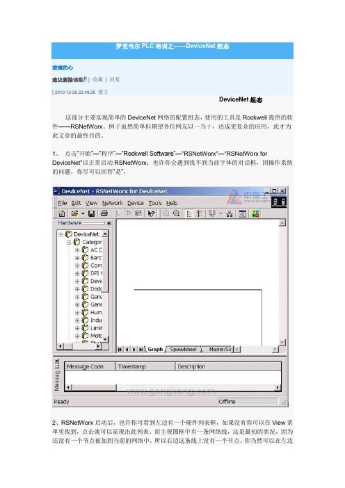
1、点击“开始”—“程序”—“Rockwell Software”—"RSNetWorx"—"RSNetWorx for DeviceNet"以正常启动RSNetWorx;也许你会遇到找不到当前字体的对话框,因操作系统的问题,你尽可以回答“是”。
2、RSNetWorx启动后,也许你可看到左边有一个硬件列表框,如果没有你可以在View菜单里找到,点击就可以显现出此列表。
而主视图框中有一条网络线,这是最初的状况,因为还没有一个节点被加到当前的网络中,所以右边这条线上没有一个节点。
你当然可以在左边的列表框里选择你目前已经连接好的设备并双击使其加到右边的网络线上,但我们不这样做,RSNetWorx有一个最简单的做法就是利用网络扫描功能,如下图:点击图中的Online 图标或点“NetWork”—"Online"菜单,则可以启动扫描功能。
2、点击“Online”图标后会弹出一个对话框,要你选择用于连接的驱动,你应该可以看到1770-KFD的连接,如果没有,则请参阅本文的第三部分。
3、选中“1770-KFD”驱动并点击OK,或直接双击,会告诉你一个同步确认对话框,点击OK。
RSNetWorx即开始Browsing Network...5、如果此对话框的进度条一直没有动作则表示你的串行通讯连接线有问题,或是你的PC 上正有其它程序使用串行口。
扫描完毕后网络上能找到的所有节点都会显示出来。
在此例中Master(1747-SDN/B)的地址为01,而1770-KFD节点地址为05。
FANUC DeviceNet IO配置说明一、 硬件连接1.系统要求a.FANUC Device Net接口板b.FANUC R-J3iC控制柜c.DeviceNet接口设备d.5芯Phoenix接口*2+专用电缆+120Ω电阻*2e.系统软件——DeviceNet Interface(J753)2.连线图以WAGO750-346 I/O模块为例,硬件连接如下:图1. DeviceNet 连接由于FANUC按照I/O个数进行分配,所以WAGO数字量模块可以单块(750-402,750-504)的加入,无须凑齐8位的倍数加入。
但是在机器人识别时,仍按照8的整数倍分配I/O。
配置的最后几位I/O无法使用。
3.MAC地址设置接口板和I/O设备均需要设置MAC地址,DeviceNet链中所有设备必须都有唯一的MAC地址。
后续软件配置中需要使用,必须配置正确。
a.FANUC接口板MAC地址设置以单通道DeviceNet接口板SST-DN3–104为例:插槽号(RACK)DIP序号(1-6位)81000000820000018300001084000011接口板MAC地址拨码开关(DIP)图2. 接口板MAC地址设置b.Device Net I/O设备MAC地址设置以WAGO(750-346)模块为例:图3. WAGO(750-346)MAC地址设置二、 软件设置完成硬件连接后,开始软件配置。
必须确保机器人先于DeviceNet设备上电,否则有很大几率出现设备无法连接的问题。
1.进入MENUS->I/O->DeviceNet界面。
将当前使用的接口卡激活(ONLINE)。
如果出现无法激活的情况,请检查接口卡的MAC地址设置。
确保DIP开关号与插槽号(RACK)相一致。
图4. 激活DeviceNet接口卡2.板卡激活后,按DIAG键进入诊断界面,开始寻找外部I/O设备。
如果不确定外部设备的MAC地址,点击BROWSE键可以自动寻找外部设备。
<EX260-SDN1/-SDN2/-SDN3/-SDN4>Installation Switch settingSet the DeviceNet node address (MAC ID), DeviceNet communication speed andfail safe mode of the SI unit with 10-element switch.General instructions on installation and maintenanceConnect valve manifold to the SI unit.Connectable valve manifolds are same as for EX250 series SI unit.Refer to the EX250 series valve manifold section in the valve catalogue for valvemanifold dimension.Power supply connector layoutGround terminalConnect the ground terminal to the ground.Resistance to ground should be 100 ohms or less.SettingNote: Each output can be set under individual conditions through the network.Replacement of the SI unit•Remove the M3 hexagon screw from the SI unit and release the SI unit from thevalve manifold.•Replace the SI unit.•Tighten the screws with the specified tightening torque. (0.6 Nm)Precautions for maintenance•Be sure to switch off the power.•Check there is no foreign matter inside the SI unit.•Check there is no damage and no foreign matter being stuck to the gasket.•Be sure to tighten the screw with the specified torque.If the SI unit is not assembled properly, inside PCBs may be damaged or liquid and/ordust may enter into the unit.Output number assignmentOutput number starts at zero and refers to the solenoid position on the manifold.LED indicationTroubleshootingThe technical document states detail troubleshooting information can be found onthe SMC website (URL )SpecificationsConnected load: 24VDC Solenoid valve with light and surge voltage suppressor of 1.5 Wor less (manufactured by SMC)Current consumption of power supply for SI unit operation: 0.1 A max.Ambient temperature for operation: -10 to50 ℃Ambient temperature for storage: -20 to60 ℃Pollution degree 2: (UL508)The technical document states detail specification information can be found on theSMC website (URL )Akihabara UDX 15F, 4-14-1, Sotokanda, Chiyoda-ku, Tokyo 101-0021, JAPANPhone: +81 3-5207-8249 Fax: +81 3-5298-5362URL Outline DimensionsThe technical document states detail outline dimensions information can be foundon the SMC website (URL )AccessoriesThe technical document states detail accessories information can be found on theSMC website (URL )PWR: M12 4-pole Plug A-codedAddress setting (switch No. 5 to 10)Set the DeviceNet node address (MAC ID) in binary coded. Address range is 0 to 63.Note: Factory default setting is 63.Communication speed setting (switch No. 3 to 4)Set the DeviceNet communication speed in binary coded.Note: Factory default setting is 125kbps.HOLD/CLEAR setting (switch No.2)Set the reaction of outputs to the communication error(All outputs will be set under the same conditions)Note: Factory default setting is CLEARHW/SW mode setting (switch No.1)Set the setting method, either by local or by network, for the setting of address andspeed.Local setting: Hardware mode (Hereinafter referred to as “HW mode”)Network setting: Software mode (Hereinafter referred to as “SW mode”)Note: Factory default setting is "HW mode" settingBUS OUT: M12 5-pole Socket A-codedConnecting cablesSelect the appropriate cables to fit with the connectors mounted on the SI unit.BUS IN: M12 5-pole Plug A-codedSetting over the DeviceNet networkThe technical document states detail setting over the network information can befound on the SMC website (URL )Diagnostic informationThe technical document states detail diagnostic information can be found on theSMC website (URL )Assembly and disassembly of the SI unitNote: Be sure to switch off the power supply when set on the switch.Note: If you are concerned about disruption of "downstream" devices whilst replacing the SI unit,use a DeviceNet tap rather than making connections to the BUS OUT connector.Fieldbus interface connector layoutNOTEWhen conformity to UL is necessary the SI unit must be used with a UL 1310Class2 power supply.Fieldbus deviceOperation ManualEX260 Series for DeviceNet TMThank you for purchasing an SMC EX260 Series Fieldbus device (Hereinafterreferred to as "SI unit" ).Please read this manual carefully before operating the product and make sure youunderstand its capabilities and limitations.Please keep this manual handy for future reference.To obtain more detailed information about operating this product,please refer to the SMC website (URL ) orcontact SMC directly.These safety instructions are intended to prevent hazardous situations and/orequipment damage.These instructions indicate the level of potential hazard with the labels of"Caution", " Warning" or "Danger". They are all important notes for safety andmust be followed in addition to International standards (ISO/IEC), Japan IndustrialStandards (JIS) and other safety regulations.OperatorNote: Specifications are subject to change without prior notice and any obligation on the part of the manufacturer.DeviceNet is a trademark of ODVA.© 2010 SMC Corporation All Rights Reserved。
DeviceNet使用说明
DeviceNet网络是工控行业的一个公开协议,它应用于广大的设备中。
例如OMRON PLC、GE PLC、MITSUBISHI PLC及其他的仪表设备。
它一个或多个主通信设备,当主站出现问题时,以这个为主站的通信将会全部中断。
以三台OMRON CJ1M+DRM21系列PLC和五台OMRON CPM2AH+CP1A-DRT21系列PLC为例说明它的使用方法:
1、以公用屏的CJ1M PLC为唯一主站,1#水机自动化机、2#机组自动化屏的CJ1M系列PLC及五台CPM2AH系列PLC为从站,说明其地址分配:(1)通信地址设定:
公用屏:00
1#机组自动化屏:01
2#机组自动化屏;02
供水控制屏:03
液压控制屏:04
排水控制箱:05
油压控制箱:06
气机控制箱:07
(2)PLC地址分配及对应关系:
Ⅰ、1#机组自动化屏公用屏(遥信、遥测)1100.00~1144.15 3300.00~3344.15
1#机组自动化屏公用屏(遥控)
1000.00~1044.15 3200.00~3244.15 Ⅱ、2#机组自动化屏公用屏(遥信、遥测)1100.00~1144.15 3345.00~3389.15
2#机组自动化屏公用屏(遥控)
1000.00~1044.15 3245.00~3289.15 Ⅲ、供水泵控制屏公用屏(遥信、遥测)
13.00~14.15 3390.00~3391.15
供水泵控制屏公用屏(遥控)
3.00~
4.15 3290.00~3291.15
Ⅳ、液压控制屏公用屏(遥信、遥测)
14.00~15.15 3392.00~3393.15
液压控制屏公用屏(遥控)
5.00~
6.15 3292.00~3293.15
Ⅴ、排水控制箱公用屏(遥信、遥测)
12.00~13.15 3394.00~3395.15
排水控制箱公用屏(遥控)
2.00~
3.15 329
4.00~329
5.15
Ⅵ、油压控制箱公用屏(遥信、遥测)
13.00~14.15 3396.00~3397.15
油压控制箱公用屏(遥控)
3.00~
4.15 3296.00~3297.15
Ⅶ气机控制箱公用屏(遥信、遥测)
12.00~13.15 3398.00~3399.15
气机控制箱公用屏(遥控)
2.00~
3.15 3298.00~3299.15
2、特别应注意的是,因为在DeviceNet网络中一个从站只能归属于一个主站,导致在上述的例子中如果机组自动化屏要向控制屏(箱)下遥控时,必须按
以下方法编制程序:
(1)、在机组自动化中的遥控命令作为遥信上传到公用屏,再在公用屏的程序中将机组自动化的的遥信MOV 到对应控制箱的遥控地址中,例如1#机组自动化要向供水泵控制屏下遥控命令,要经过以下过程:
Ⅰ、在1#机组自动化中将遥控命令MOV 到1000中;
Ⅱ、在公用屏中将命令MOV 到供水控制屏的遥控命令地址:
MOV 3300 3290
485或422转换头 plc
1
RDB 2
RDA 3
SDA 4
SDB
差动保护平衡系数整定及计算方法:列如
某站有一台10MVA 主变、110KV 侧CT 角型接线、变比100/5;10KV 侧CT 星型接线,变比600/5
高压侧额定电流为
I =Klh U Kjx
P **3*=4.54
低压侧额定电流为
I =Klh U Kjx
P **3*=4.8
低压侧不平衡系数选为4.54/4.8=0.95
Kjx -接线系数,CT 为星型接线时:Kjx =1
CT 为角型接线时:Kjx =3
K lh -CT 变比
三圈变31500/11655/9845KVA
电压121、38.5、6.3KV
一次额定电流 Ie1=
3*11Ue Se =3*12131500=150.3
Ie2=
3*22Ue Se =3*12111655=174.8
Ie3=3*33
Ue Se =3*3.619845
=1818.7
二次额定电流
Ie1=150.3×200
5=3.76 Ie2=174.8×200
5=4.73 Ie3=1818.7×
25005=3.64
正绞线:电脑与HUB相联使用的接法,线的两端都是这个接发。
反绞线:两台电脑之间连起来的接法。