MAX1963ETT180-T中文资料
- 格式:pdf
- 大小:319.11 KB
- 文档页数:12

第二章一、判断题1、市场风险可以通过多样化来消除。
(×)2、与n个未来状态相对应,若市场存在n个收益线性无关的资产,则市场具有完全性。
(√)3、根据风险中性定价原理,某项资产当前时刻的价值等于根据其未来风险中性概率计算的期望值。
(×)4、如果套利组合含有衍生产品,则组合中通常包含对应的基础资产。
(√)5、在套期保值中,若保值工具与保值对象的价格负相关,则一般可利用相反的头寸进行套期保值。
(×)二、单选题1、下列哪项不属于未来确定现金流和未来浮动现金流之间的现金流交换?(B)A、利率互换B、股票C、远期D、期货2、关于套利组合的特征,下列说法错误的是(A)。
A.套利组合中通常只包含风险资产B.套利组合中任何资产的购买都是通过其他资产的卖空来融资C.若套利组合含有衍生产品,则组合通常包含对应的基础资产D.套利组合是无风险的3、买入一单位远期,且买入一单位看跌期权(标的资产相同、到期日相同)等同于(C)A、卖出一单位看涨期权B、买入标的资产C、买入一单位看涨期权D、卖出标的资产4、假设一种不支付红利股票目前的市价为10元,我们知道在3个月后,该股票价格要么是11元,要么是9元。
假设现在的无风险年利率等于10%,该股票3个月期的欧式看涨期权协议价格为10.5元。
则(D)A.一单位股票多头与4单位该看涨期权空头构成了无风险组合B. 一单位该看涨期权空头与0.25单位股票多头构成了无风险组合C . 当前市值为9的无风险证券多头和4单位该看涨期权多头复制了该股票多头D .以上说法都对三、名词解释1、套利答:套利是在某项金融资产的交易过程中,交易者可以在不需要期初投资支出的条件下获取无风险报酬。
2、 阿罗-德不鲁证券答:阿罗-德不鲁证券指的是在特定的状态发生时回报为1,否则回报为0的资产。
3、 等价鞅测度答:资产价格t S 是一个随机过程,假定资产价格的实际概率分布为P ,若存在另一种概率分布*P 使得以*P 计算的未来期望风险价格经无风险利率贴现后的价格序列是一个鞅,即()()rt r t t t t S e E S e ττ--++=,则称*P 为P 的等价鞅测度。

Eaton PDG23G0225E2WJEaton Power Defense molded case circuit breaker, Globally Rated, Frame 2, Three Pole, 225A, 35kA/480V, PXR20 LSI w/ Modbus RTU, ZSI and Relays, Standard Line and Load (PDG2X3TA225)Eaton Power Defense molded case circuit breakerPDG23G0225E2WJ 78667932808888.9 mm 152.4 mm 104.6 mm 1.82 kg Eaton Selling Policy 25-000, one (1) year from the date of installation of theProduct or eighteen (18) months from thedate of shipment of the Product,whichever occurs first.RoHS Compliant UL 489IEC 60947-2CCC MarkedCSAProduct NameCatalog Number UPCProduct Length/Depth Product Height Product Width Product Weight WarrantyCompliancesCertifications225 AComplete breaker 2Three-polePD2 Global Class A PXR 20 LSIModbus RTU600 Vac600 VStandard Line and Load35 kAIC at 480 Vac 10 kAIC Icu @125 Vdc36 kAIC Icu/ 36 kAIC Ics/ 75.6 kAIC Icm @380-415V (IEC) 8 kAIC Icu/ 4 kAIC Ics/ 16.8 kAIC Icm @690V (IEC) 55 kAIC Icu/ 55 kAIC Ics/ 121 kAIC Icm @240V (IEC) 20 kAIC Icu/ 15/13 kAIC Ics/ 42 kAIC Icm @525V South Africa (IEC)10 kAIC Icu @250 Vdc 65 kAIC @240V (UL) 18 kAIC @600V (UL/CSA)30 kAIC Icu/ 22.5 kAIC Ics/ 63 kAIC Icm @440V (IEC) 35 kAIC @480V (UL)25 kAIC Icu/ 20 kAIC Ics/ 52.5 kAIC Icm @480V Brazil (IEC)225 AAmperage Rating Circuit breaker frame type Frame Number of poles Circuit breaker type Class Trip Type Communication Voltage rating Voltage rating - max TerminalsInterrupt rating Interrupt rating range Trip rating3D CAD drawing packageEaton Power Defense MCCB PDG23G0225E2WJ 3D drawingApplication notesConsulting application guide - molded case circuit breakersPower Xpert Protection Manager x64Power Xpert Protection Manager x32BrochuresPower Defense technical selling bookletPower Defense molded case circuit breaker selection posterPower Defense brochurePower Defense molded case circuit breakers - Frame 2 product aidCatalogsMolded case circuit breakers catalogPower Xpert Release trip units for Power Defense molded case circuit breakersCertification reportsEU Declaration of Conformity - Power Defense molded case circuit breakersPDG4 CB reportPDG4 CCC certificationPower Defense Declaration concerning California’s Proposition 65PDG2 CB reportInstallation instructionsPower Defense Frame 2 global terminal shield, 3 pole - IL012330EN Power Defense Frame 2 shunt trip UVR instructions - IL012130EN Power Defense Frame 2 clamp terminal (steel), 20A, 3 pole instructions - IL012246EN H03Power Defense Frame 2 tunnel terminal (aluminum), 100A, 3 pole instructions - IL012237EN H03Power Defense Frame 2 box terminal (steel), 100A, 3 pole instructions - IL012234EN H03Power Defense Frame 2 box terminal (aluminum), 225A, 3 pole instructions - IL012235EN H03Power Defense Frame 2 multi wire connector kit -PDG2X3(2)(4)TA2253W instructions - IL012243EN H01Power Defense Frame 2 locking devices and handle block instructions - IL012149ENPower Defense Frame 2 terminal kit - PDG2X3(2)(4)TA225RF instructions - IL012245EN H01Power Defense Frame 1-2-3-4 IP door barrier assembly instructions -IL012278ENPower Defense Frame 2 tunnel terminal kits - PDG2X1TA225K instructions- IL012239EN H01Power Defense Frame 2 terminal kit - PDG2X3(2)(4)TA150RF instructions - IL012244EN H01Power Defense Frame 2 tunnel terminal (aluminum), 50A, 3 pole instructions - IL012236EN H03Power Defense Frame 1 IEC and Frame 2 Rotary Mechanism with NFPA Handle Attachment Instructions (IL012260EN).pdfPower Defense Frame 2 handle mech direct rotary handle instructions - IL012134ENPower Defense Frame 2 handle mech variable depth rotary handle instructions - IL012136ENPower Defense Frame 2/3/4/5/6 voltage neutral sensor module wiring instructions – IL012316ENPower Defense Frame 2 screw terminal_end cap kit, 225A, 3 pole instructions - IL012258EN H01Power Defense Frame 2 Direct Rotary Handle Assy With Interlock Version Instructions (IL012138EN).pdfPower Defense Frame 2 tunnel terminal (aluminum), 150A, 3 pole instructions - IL012238EN H03Power Defense Frame 2 PDG2 and PDC(E)9 breaker instructions -IL012106ENPower Defense Frame 2 multi wire connector kit -PDG2X3(2)(4)TA2256W instructions - IL012242EN H01Power Defense Frame 2 bell alarm switch instructions - IL012154EN Power Defense Frame 2 Bell Alarm Switch Instructions (IL012154EN).pdfInstallation videosPower Defense Frame 2 withTMTU, Shunt Trip_UVR Animated Instructions.rhPower Defense Frame 2 Bell Alarm with PXR Animated Instructions.pdf.rh Power Defense Frame 2 Handle Mech Variable Depth Rotary Handle Animated Instructions.rhPower Defense Frame 2 Locking Devices and Handle Block Animated Instructions.pdf.rhPower Defense Frame 2 TMTU Aux, Alarm, ST and UVR Animated Instructions.rhMultimediaPower Defense Frame 2 Aux, Alarm, Shunt Trip, and UVR How-To Video Power Defense Frame 2 Direct Rotary Handle Mechanism Installation How-To VideoPower Defense Frame 3 Variable Depth Rotary Handle MechanismEaton Corporation plc Eaton House30 Pembroke Road Dublin 4, Ireland © 2023 Eaton. All Rights Reserved. Eaton is a registered trademark.All other trademarks areproperty of their respectiveowners./socialmediaInstallation How-To VideoPower Defense Frame 2 Variable Depth Rotary Handle Mechanism Installation How-To VideoPower Defense molded case circuit breakers Power Defense Frame 6 Trip Unit How-To Video Power Defense BreakersEaton Power Defense for superior arc flash safety Power Defense Frame 5 Trip Unit How-To Video Eaton Specification Sheet - PDG23G0225E2WJ Power Defense time current curve Frame 2 - PD2Intelligent power starts with accurate, actionable data Single and double break MCCB performance revisited Intelligent circuit protection yields space savingsMolded case and low-voltage power circuit breaker health Making a better machineMolded case and low-voltage breaker health Safer by design: arc energy reduction techniquesSpecifications and datasheetsTime/current curvesWhite papers。


■ 上海西门子开关有限公司2的严格管理不仅贯穿于内部生产的各个流程,同时延伸至对供应商的日年在闵行经年底公司二期厂房扩建工程的竣平方米,体现了西门子根植于中国、长期服务于中国客户的信心和承诺。
2004年研发中心作为西门子输配电全球研发中心的组成部分,可同步共享西门子最新的技术和资源。
通过预测客户的需求,开发质量稳定可靠的创新型产品和为客户度身定制方案,使客户的业务增值。
一支反应迅速、装备精良、经验丰富的售后服务队伍和遍布全国的服务网点构成了公司一套高效的现场服务应对系统,负责指导产品现场安装和操作,并承诺在最短时间内对紧急情况作出应对,将客户的断电年位列上海市年被上海市电器行业协会评为行业名优产品。
公司因其良好的商业信誉被评为“守合同重信而被电气时代以及专3AH3及面向全球同步发售所有产品均在西安高压电器研究所通过型式试验,确保产品的运行安全和操作人员的人身安全。
目 录ContentsSiemens Switchgear Ltd., Shanghai (SSLS) is a joint venture of Siemens Ltd., China (SLC) and Shanghai Power Transmission & Distribution Company, holding the manufacturing license to apply the latest tech-nology of Siemens vacuum circuit-breaker and medium voltage switchgear in P. R. China.Since established in 1993, relying on Siemens powerful resources and internal boundless cooperation, SSLS has provided reliable products, first-class service and innovative solutions for more than two thousand key projects both for domestic and overseas. SSLS has established a good reputation and leading position in China due to its large contribu-tion to the technique innovation and development of local switchgear industry.SSLS is a market oriented company with commitment to customers’satisfaction and to fulfill the demands for the medium voltage switchgear, with high quality and excellent reliability, by means of dynamically intro-ducing and constantly developing the applicable technique and prod-ucts to the local market. Customer’s success is our first priority. We pledge to provide the most value-added product and service, promise on-time delivery, and establish solid business partner relationship with customers, in result to create the maximum value for our customers.SSLS began to implement the customer-oriented quality management early in1996, and established a comprehensive quality management system in 2004 integrated with ISO9001, ISO14001 and OHSAS18001. The company utilizes the highly sophisticated machines and testing fa-cilities in production process. The high qualification of operators along with continuous in process quality control guarantee our well established and high quality standards at all times. The strict quality control is not only carried out throughout entire production processes, but also ex-tended to the daily management of our suppliers. We take environment protection as our social responsibility; meanwhile closely look after employees’ occupational safety and health.To meet the growing marketing demands, a modern factory was built up in Minhang Economic & Technological Development Zone in 2004. With the completion of second phase expansion at the end of 2006, the land plot increased to 50000sqm and shop floor to 23000sqm, which em-bodies Siemens’ commitment to root in China and serve long-term for Chinese customers.According to company’s strategy to create more competence and shorter time-to-market, SSLS R&D center was established in 2004. R&D cen-ter closely integrates into the Siemens PTD global R&D network, could share the latest Siemens technique and resources in-phase. By pre-dicting the market needs, SSLS fosters R&D in developing reliable and innovative products and tailored solutions to add value for customer’s business.Siemens switchgear has an effective system of on-site servicing from a quick-respondent, well-equipped and rich experienced field service team and a network setup all over China. The team is responsible for the guidance of on-site installation and operational safety, commit to re-spond to emergency calls within the shortest possible time and to mini-mize down time.SSLS was ranged as the Top 500 Revenue of Industrial Companies in Shanghai 7 years in row since 2000. The products won the title of Shang-hai Reputed Product 4 years in row since 2003. The company was awarded as “Good Credit Enterprise” due to its high commercial credit, and won the title of “Top 10 Fast-growing Companies in China Electric Industry” in 2006 due to over 30% increase of sales revenue continu-ously over the past three years.PRODUCT INTRODUCTIONSSLS provides air insulated Switchgear rated from 7.2 to 24kV with type 8BK20, 8BK30, 8BK40 and specially designed for Chinese market in 2007 NXAIR S, and vacuum circuit breakers type 3AH3, 3AH5, 3AH2-EP as well as SION, the latest generation of Siemens VCB synchro-nously selling world wide.All products are type tested in XIHARI to ensure the safety of personnel and operation.公司简介Company Introduction■产品介绍3■ 上海西门子开关有限公司4● Draw-out section and access door fully inte-grated interlock system.● Safe and easy draw-out section movementbehind closed cubicle door.● Easy draw-out section transfer or exchange,using central service truck, independent of floor quality.● Earthed metal partitions and shutters.● Connection of HV cables is available from front or rear part of the panel optionally.● Back-to-back or face-to-face designs available for double bus-bar design.●Reinforced insulation which fulfills Chinese system and local climate.●Direct line-up with 8BK30 Vacuum ContactorSwitchgear.● 可移开部分与柜门之间有可靠的联锁● 前门关闭后,能够很安全而且容易地移动可移开部分● 先进的中置式结构,使用专门的小车能够方便地搬运或更换可移开部分,不受现场地面平整度的限制● 金属隔板与活门均接地● 根据用户需要,可由前门或开关柜的后部进行电缆接线● 开关柜可以面对面布置,也可以背靠背布置(双母线回路)●加强了绝缘,更适合中国电力系统和气候● 可直接与8BK30型开关柜(F - C 回路)联接供电典型客户上海供电局北京供电局兰溪电厂秦皇岛港口宁波小港纸业兰州石化TYPICAL CUSTOMER Shanghai PSBBeijing PSBLanxi Power PlantQinghuangdao HarborNingbo Xiaogang Paper MillLanzhou Petro 产品特点SPECIFIC FEATURES 电气技术数据 ELECTRICAL DATA (MAXIMUM VALUES )8BK20 Switchgear with Draw-Out Circuit-Breakers, Air-Insulated, Metal Clad8BK20型金属封闭/铠装可移开式空气绝缘断路器柜■ 产品介绍5● Draw-out section and door integrated in the inter-lock system.● Minimal space requirement.● Vacuum contactor and HVHRC fuses on draw-outsection. Vacuum contactor is able to operate fre-quently due to its long mechanic life-1 millionoperations.● Draw-out section easily to move inside the cubicle.● Cable connection in front of cubicle.● Directly line-up with circuit-breaker panel of type 8BK20.● Special wheels on bottom of draw-out section provide an easy movement during in and out the cubicle.● Reinforced insulation to meet Chinese system andlocal climate.● 可移开部分与室门之间装有可靠的联锁装置● 占用空间少● 可移开部分装有真空接触器和高压限流熔断器。

Motor control and protectionICON familyStart easily Protect preciselyIntroducing Eaton’s new contactor range for AC-3 applications to 170A. Perfectly suited for applications in the commercial and industrial segments for panel builders and machinery OEMs.The contactor has a smaller footprint than the existing xStart series and offers application adjusted ratings.Icon Contactors SeriesCoil voltages available are 24V50/60HZ, 110V50/60HZ, 230V50/60HZ, 400V50/60HZ, DC24V .Basic devices Rated operational current Max. motor rating for three-phase motors 50 - 60 Hz Conventional thermal current I th = I e AC-1at 40°C A Open Contact AC-3AC-3AC-4380 V 400 V I e220 V 230 V P 380 V 400 V P 660 V 690 V P 220 V 230 V P 380 V 400 V P 660 V 690 V P N/O = Normallyopened contact N/C = Normally 4 pole, 3 poleConnection type: Screw terminals9 2.5 4 4.5 1.5 2.5 3.6 20 – 1 N/C 12 3.5 5.5 6.5 2 3 4.4 20 1 N/O –12 3.5 5.5 6.5 2 3 4.4 20 – 1 N/C 15 4 7.5 7 2 3 4.4 20 1 N/O –154 7.5 7 2 3 4.4 20 – 1 N/C 3 poleConnection type: Screw terminals1857.511 2.5 4.56.5 401 N/O–18 5 7.511 2.5 4.5 6.5 40 – 1 N/C 257.51114 3.5 68.5 401 N/O–25 7.5 1114 3.5 6 8.5 40 – 1 N/C 32101515 4 710 451 N/O–32 10 1515 4 710 45 – 1 N/C 381118.515 4 710 451 N/O–3811 18.5 15 4 710 45 – 1 N/C 3 poleConnection type: Screw terminals40 12.5 18.523 5 912 60 1 N/O 1 N/C 50 15.5 2230 6 1014 80 1 N/O 1 N/C 65 20 3035 7 1217 98 1 N/O 1 N/C 7222 3735 7 1217 98 1 N/O 1 N/C 3 poleConnection type: Screw terminals80 25 3737112015110 1 N/O 1 N/C 95304545 1120151301 N/O1 N/C3 poleConnection type: Screw terminals115 37 5590 17 2843 160 ––150 48 75 96 20 3348 190 ––1705290140 20 3348 203––CMN00027DILM9-01N CMN00038DILM12-10N CMN00049DILM12-01N CMN00060DILM15-10N CMN00071DILM15-01N CMN00082DILM18-10N DILM18-01N CMN00104DILM25-10N DILM25-01N(CMN00126DILM32-10N DILM32-01N CMN00148DILM38-10N DILM38-01N CMN00170DILM40-11N DILM50-11N DILM65-11N DILM72-11N DILM80-11N DILM95-11N DILM115N DILM150N DILM170N (...)(...)(...)(...)(...)(...)(...)(...)(...)(...)(...)(...)(...)(...)(...)(...)(...)(...)(...)(...)(...)(...)• Phase failure sensitivity and temperature compensation • Reset pushbutton manual/auto • Test/off pushbutton• Auxiliary contact (1 N/O + 1 NC)•Fitted directly on the contactor of the maximum current to 175AIcon Overload relays ZB..N series0.1 – 0.16CMN00333CMN00335ZB12N-1,6CMN00336ZB12N-2,4CMN00337ZB12N-4CMN00338ZB12N-6CMN00339ZB12N-10CMN00340ZB12N-12CMN00341ZB12N-161 – 1.5CMN00352ZB32N-24CMN00353ZB32N-30CMN00354ZB32N-36CMN00355ZB32N-38CMN00356Setting range of overload releasesCircuit symbolAuxiliary contactFor use withI r AN/O = normally open contact N/C = normally closed contact0.4 – 0.6 1 N/O 1 N/C 0.6 – 1 1 N/O 1 N/C 1 – 1.6 1 N/O 1 N/C 1.6 – 2.4 1 N/O 1 N/C 2.4 – 4 1 N/O 1 N/C 4 – 6 1 N/O 1 N/C 6 – 10 1 N/O 1 N/C 9 – 12 1 N/O 1 N/C 12 –161 N/O1 N/C 17 – 24 1 N/O 1 N/C 22 – 30 1 N/O 1 N/C 29 – 36 1 N/O 1 N/C 33 – 381 N/O1 N/COverload relaysIcon Overloads ZB…N seriesSetting range of overload releasesCircuit symbolAuxiliary contactFor use withI r AN/O = normally open contact N/C = normally closed contact63 – 80 1 N/O 1 N/C 77 – 971 N/O1 N/C50 – 70 1 N/O 1 N/C 70 – 100 1 N/O 1 N/C 95 – 125 1 N/O 1 N/C 120 – 150 1 N/O 1 N/C 145 – 1751 N/O1 N/COverload relays Part no.Article no.– 25CMN00363– 50– 35– 25 – 50ZB95N-50 – 35ZB150N-35Icon Contactor Relays DILA…N seriesWiring method: Screw terminals Basic devices with interlocked opposing contacts ContactRated operational current AC – 15Conventional thermal current at 55°CN/O = Normally opened contact N/C = Normally closed contact220 V 230 V 240 V I e A380 V 400 V 415 V I e AI th A4 N/O – 4 416 3 N/O 1 N/C 4 4 16 2 N/O 2 N/C 4 4 16 1 N/O 3 N/C 4416–4 N/C4416DILA-40N DILA-31N DILA-22N DILA-13N DILA-04N(Coil voltages available are 24V50/60HZ, 110V50/60HZ, 230V50/60HZ, 400V50/60HZ, DC24V .• Varied 4-pole contact configurations • Conventional thermal current (Ith): 16A• Identical construction sizes for AC- and DC-operated contactor relays •Integrated surge suppressors for DC-operated contactor relaysA complete range of accessories are available for the Icon series, such as:• Auxiliary contacts (top mount)• Auxiliary contacts (side mount)• RC Suppressors• Varistor Suppressors• Pneumatic timer modules • Mechanical Interlocks • Sealable Shrouds•External Reset Button(...)(...)(...)(...)(...)E a t o n10 Kent RoadMascot NSW 2020Tel: 1300 332 866Fax: (02) 9693 1258Email: ************************ Eaton is a registered trademarkof Eaton Corporation.All trademarks are property of their respective owners.For more information about Eaton visit: Eaton’s mission is to improve the quality of life and the environment through the use of power management technologies and services. We provide sustainable solutions that help our customers effectively manage electrical, hydraulic, and mechanical power – more safely, more effi ciently, and more reliably. Eaton’s 2019 revenues were $21.4 billion, and we sell products to customers in more than 175 countries. We have approximately 95,000 employees.For more information about Eaton visit: 。


T180 控 制 箱使 用 说 明 书小原(南京)机电有限公司为了安全地使用本产品,使用前,务必熟读安全注意事项,并在充分理解的基础上使用本产品。
阅读后,请将本手册保管在规定的场所。
目录Ⅱ.控制箱部分1.使用注意事项------------------------------------------------------------------------------------ 32.主要特点------------------------------------------------------------------------------------------ 43.主要技术规格------------------------------------------------------------------------------------ 54.安装------------------------------------------------------------------------------------------------ 65.操作------------------------------------------------------------------------------------------------ 116.维护------------------------------------------------------------------------------------------------ 237.参考资料------------------------------------------------------------------------------------------ 288.附录----------------------------------------------------------------------------------------------- 441.安全注意事项为避免人身伤害、防止本产品及与本产品相连接的其它产品受到损坏,使用前请阅读以下安全注意事项。

变频电机参数规格(总8页) -CAL-FENGHAI.-(YICAI)-Company One1-CAL-本页仅作为文档封面,使用请直接删除Y P2系列宽频三相异步电动机YP2 SERIES WIDE FREQUENCY THREE PHASE INDUCTION MOTOR机座号:63~355 功率: 0.12~315kW工作制 :S1 绝缘等级: F基准频率:50Hz 调频范围:30~60Hz适用于:一般场所和无特殊要求的机械,如金属切削机床、泵、风机、运输机械、搅拌机、农业机械、食品机械等。
Applications: General purpose including cutting machines, pumps, fans, conveyors, machines tools of farm duty and food process.特点:外型美观、噪声低、振动小、绝缘等级为F级、外壳防护等级为IP54或IP55、使用频率范围30~60Hz(30~50Hz为变转矩范围,50~60Hz为恒功率范围)。
Features: High efficiency and energy saving、low noise and little vibration. The insulation class is F、the protective class is IP54 or IP55、frequency variable range 30-60Hz(30-50Hz for variable torque range, 50-60Hz for constant output range)使用条件:海拔不超过1000m。
环境温度随季节变化,但最高不超过+40℃,最低不低于-15℃,无特殊环境要求。
Circumstance For Use: The altitude not exceeding 1000m above sea level. The ambient temperature subject to seasonal variations but not exceeding 40℃ and not less than -15℃,No special environmental requirements.mm(机座无底脚、端盖上有小凸缘)机座号Fram e极数poles 安装尺寸 Mounting Dimension 外形尺寸 Overall Dimension A B C D E F G H K M N P R S T 凸缘孔数 AA AB AC AD BB HA HD 63M 2.4110 80 40 11 23 4 8.5 63 7 75 60 90 0 M5 2.54 30 135 130 70 110 8 180 71M2.4.6 112 90 45 14 30 5 11 71 7 85 70 105 0 M6 2.54 32 150 145 80 120 8 195 80M 2.4.6.8 125 100 50 19 406 15.580 10 100 80 120 0 M6 3 4 32 165 175 145 130 10 214 90S 2.4.6.8 140 100 56 24 50 8 20 90 10 115 95 140 0 M8 3 4 34 180 195 155 140 12 250 90L2.4.6.8 140 125 56 24 50 8 20 90 10 115 95 140 0 M8 34 34 180 195 155 165 12 250 100L 2.4.6.8 160 140 63 28 60 8 24 100 12 130 110 160 0 M8 3.5 4 39 205 215 180 186 14 270 mmB3(机座带底脚、端盖无凸缘)外形及安装尺寸 Dimensions mm外形及安装尺寸 Dimensions mmnotice常用的安装结构型式,以及适用的机座号见下表“√”表示可以制造生产的结构型式。
用于Peltier模块的集成温度控制器概论MAX1978 / MAX1979是用于Peltier热电冷却器(TEC)模块的最小, 最安全, 最精确完整的单芯片温度控制器。
片上功率FET和热控制环路电路可最大限度地减少外部元件, 同时保持高效率。
可选择的500kHz / 1MHz开关频率和独特的纹波消除方案可优化元件尺寸和效率, 同时降低噪声。
内部MOSFET的开关速度经过优化, 可降低噪声和EMI。
超低漂移斩波放大器可保持±0.001°C的温度稳定性。
直接控制输出电流而不是电压, 以消除电流浪涌。
独立的加热和冷却电流和电压限制提供最高水平的TEC保护。
MAX1978采用单电源供电, 通过在两个同步降压调节器的输出之间偏置TEC, 提供双极性±3A输出。
真正的双极性操作控制温度, 在低负载电流下没有“死区”或其他非线性。
当设定点非常接近自然操作点时, 控制系统不会捕获, 其中仅需要少量的加热或冷却。
模拟控制信号精确设置TEC 电流。
MAX1979提供高达6A的单极性输出。
提供斩波稳定的仪表放大器和高精度积分放大器, 以创建比例积分(PI)或比例积分微分(PID)控制器。
仪表放大器可以连接外部NTC或PTC热敏电阻, 热电偶或半导体温度传感器。
提供模拟输出以监控TEC温度和电流。
此外, 单独的过热和欠温输出表明当TEC温度超出范围时。
片上电压基准为热敏电阻桥提供偏置。
MAX1978 / MAX1979采用薄型48引脚薄型QFN-EP 封装, 工作在-40°C至+ 85°C温度范围。
采用外露金属焊盘的耐热增强型QFN-EP封装可最大限度地降低工作结温。
评估套件可用于加速设计。
应用光纤激光模块典型工作电路出现在数据手册的最后。
WDM, DWDM激光二极管温度控制光纤网络设备EDFA光放大器电信光纤接口ATE特征♦尺寸最小, 最安全, 最精确完整的单芯片控制器♦片上功率MOSFET-无外部FET♦电路占用面积<0.93in2♦回路高度<3mm♦温度稳定性为0.001°C♦集成精密积分器和斩波稳定运算放大器♦精确, 独立的加热和冷却电流限制♦通过直接控制TEC电流消除浪涌♦可调节差分TEC电压限制♦低纹波和低噪声设计♦TEC电流监视器♦温度监控器♦过温和欠温警报♦双极性±3A输出电流(MAX1978)♦单极性+ 6A输出电流(MAX1979)订购信息* EP =裸焊盘。

Power source is warranted for three years, parts and labor.Issued Dec. 2016 • Index No. DC/35.0Maxstar 280Maxstar 280 DXMaxstar ®280SeriesUpdate and expand. Front panel memory card data port provides the ability to easily update software and expand product features.Visit /TIGSoftware for the latest software updates and expansions.Pro-Set ™eliminates the guesswork when setting weld parameters. Use Pro-Set when you want the speed, convenience and confidence of preset controls. Simply select the feature and adjust until Pro-Set appears on the display.Sleep timer conserves electricity. This programmable feature will power down the machine if it sits idle for a specific time.Allows for any input voltage hookup (208–575 V) with no manual linking,providing convenience in any job setting.Ideal solution for dirty or unreliable power.Cooler Power Supply (CPS). An integrated 120-volt dedicated-usereceptacle to power the Coolmate ™1.3.The power switch on the Maxstar also activates the receptacle to help prevent torch failure. Available on select models,see page 6.Blue Lightning ™high-frequency (HF) arc starter for non-contact arc initiation.Provides more consistent arc starts and greater reliability compared to traditional HF arc starters.Meter calibration allows digital meters to be calibrated for certification.Wind Tunnel Technology ™protects internal electrical components from airborne contaminates, extending the product life.Fan-On-Demand ™power source cooling system operates only when needed, reducing noise, energy use and the amount of contaminants pulled though the machine.DC TIG FeaturesPulse. Pulsing can increase puddle agitation, arc stability and travel speeds while reducing heat input and distortion. DX models provide extended ranges.Exceptionally smooth and precise arc for welding exotic materials.DC Stick FeaturesDual schedule allows operators to switch welding parameters for specific electrodes without readjusting the machine,minimizing downtime and enhancing quality. Base model only (not DX).DIG control allows the arc charac t eristics to be changed for specific applications and electrodes. Lower the DIG setting for smooth running electrodes like E7018 and increase the DIG setting for stiffer, more penetrating electrodes like E6010. Hot Start ™adaptive control provides positive arc starts without sticking.Stick-Stuck detects if the electrode is stuck to the part and turns the welding output off to safely and easily remove the electrode. Menu selectable.TIG/Stick WeldingPower SourceMiller Electric Mfg. Co.An ITW Welding Company 1635 West Spencer Street P.O. Box 1079Appleton, WI 54912-1079 USAEquipment Sales US and Canada Phone: 866-931-9730FAX: 800-637-2315International Phone: 920-735-4554International FAX: 920-735-41252Performance DataCoolmate 1.3 Cooler*Refer to owner’s manual for 208 V output ratings and duty cycle. **Low OCV sense voltage for stick and Lift-Arc ™TIG.IP23 rating — This equipment is designed for outdoor use. It may be stored, but is not intended to be used outside during precipitation unless sheltered.Operating temperature range is 14 to 104°F (-10 to 40°C). Storage temperature range is -22 to 149°F (-30 to 65°C). Portions of the preceding text are contained in EN 60974-1:“Welding power sources for arc welding equipment.”All CE models conform to the applicable parts of the IEC 60974 series of standards.Certified by Canadian Standards Association to both the Canadian and U.S. Standards.*Refer to owner’s manual for 208 V output ratings and duty cycle.3Weldcraft ™W-280 (WP-280) TIG TorchTIG Upgrade Chart•Two-piece torch head and exclusive Super Cool ™Technology provides additional surface area to increase cooling efficiency and capacity •Torch body includes an anti-rotation feature and multi-position locking to prevent handle movement during welding and improve operator control•Secure mechanical fittings and connections minimize leakage4Maxstar ®280 Control PanelDC TIG (HF Start)1. Tungsten Size = .020–1/8 in. or .05–3.2 mm2. Remote Trigger = STD/HOLD/OUTPUT ON DC TIG (Lift-Arc)1. Tungsten Size = .020–1/8 in. or .05–3.2 mm2. Remote Trigger = STD/HOLD/OUTPUT ON DC Stick (Schedule 1 and 2)1. Hot Start = ON/OFF2. Remote Trigger = OUTPUT ON/HOLD/STD1. Arc Time 0.0–9,999 hours 0.0–59 minutes 0–999,999 cycles Resettable2. Error Log = Error event recorder3. Sleep Timer = 1/5/10/15/30/45MIN/1HR4. Stick Stuc = OFF/ON5. OCV = LOW/NORM6. Cooler Power = AUTO/OFF (only on Maxstar models with CPS )7. Machine Reset8. Software Number9. Serial NumberUser Menu (Hold Menu button three seconds.)Tech Menu (Hold Menu button five seconds.)1.Standby Switch2.Voltmeter Display3.Ammeter Display4.Output Contactor “On” Indicator5.DC TIG (HF Start) Process Menu ParametersAmperage 1–280 A**Pulse* Off–250 PPSPostflow Auto/Off–50 seconds 6.DC Stick (Schedule 1) Process Menu ParametersAmperage 5–280 A DIG* Off–100%7.Memory Card Port 8.Activity Indicator 9.Encoder Control 10.Menu Ranges11.DC TIG (Lift-Arc) Process Menu ParametersAmperage 1–280 A**Pulse* Off–250 PPSPostflow Auto/Off–50 seconds 12.DC Stick (Schedule 2) Process Menu ParametersAmperage 5–280 A DIG* Off–100%13.Process Selector*Pro-Set parameter selectable. **Amperage range is tungsten size dependent.5Maxstar ®280 DX Control Panel1. Tungsten Size = .020–1/8 in./GEN or .05–3.2 mm2. Remote Trigger = 3T/4T/4TL/4TE/4Tm3. Stick Hot Start = ON/OFF1. Arc Time 0.0–9,999 hours 0.0–59 minutes 0–999,999 cycles Resettable2. Error Log = Error event recorder3. Sleep Timer = 1/5/10/15/30/45MIN/1HR4. Stick Stuc = OFF/ON5. OCV = LOW/NORM6. Weld Timers = OFF/ON7. Cooler Power = AUTO/ON/OFF (only on Maxstar models with CPS )8. Locks = OFF/1–49. Meter Display10. External Pulse Control = OFF/ON 11. Machine Reset 12. Software Number 13. Serial NumberUser Menu (Press Gas and Amperage buttons.)Tech Menu (Hold Gas and Amperage buttons five seconds.)1. 2.Voltmeter Display 3.Ammeter Display4.Process/ TIG: HF impulse, Lift-ArcArc Starting Stick: Adaptive Hot Start 5.Output Control Standard remote,2T trigger hold, Output on 6.Pulser ControlPulses per Second* DC: 0.1–500 PPS Peak Time* 5–95%Background Amps* 5–95%8.Activity Indicator 9.Encoder Control 10.Amperage Button11.Gas/DIGPreflow 0.0–25.0 seconds Postflow Auto/Off–50 seconds DIG* Off–100%12.Sequencer ControlInitial Amps 1–280 AInitial Time 0.0–25.0 seconds Initial Slope 0.0–50.0 seconds Weld Time 0.0–999 seconds Final Slope 0.0–50.0 seconds Final Amps 1–200 AFinal Time 0.0–25.0 seconds*Pro-Set parameter selectable.6Maxstar ®280 Models/Packages907552Maxstar shown.Build an Air-Cooled PackageSelect desired stock number for each step.301311 kit shown.907538002Maxstar 280TIGRunner ®shown with four bottles of 043810Low-Conductivity Coolant.194744 remote shown.300990 kit shown.Build a Water-Cooled PackageSelect desired stock number for each step.Protective Cover 301382Fits Dynasty 210/280 and Maxstar 280.Small Runner ™Cart 301318Designed for Dynasty/Maxstar 210 and 280 with or without a Coolmate 1.3 cooler. Cart features single cylinder rack, foot pedal holder, two cable/torch holders,and two TIG filler holders.Coolmate ™1.3 300972 120 V1.3-gallon cooler designed to cool torches up to 280 amps.Performance TIG Gloves 263345X-Small 263346Small 263347Medium 263348 Large 263349X-LargeCompletely unlined, goat grain leather with triple-padded palm.Memory Card (Blank) 301080A blank, commercially available memory card used for transferring software updates and expandable features from your computer to the machine.Memory Card Expansion301151 14-Pin Automation ExpansionProvides the ability to access common automation functions through the 14-pin connection.301152 14-Pin Modbus ®ExpansionProvides the ability to access basic and advanced functions through the 14-pin connection.TIG Torches, Kits and ConnectorsContractor Kits301309 150 A RFCS-14 HD Foot Pedal Kit 301311 150 A RCCS-14 Fingertip KitAll-in-one TIG/stick welding kit comes with either a RFCS-14 HD foot control OR RCCS-14 fingertip control, Weldcraft ™A-150 TIG torch, 200-amp stick electrode holder with 15-foot (4.6 m) cable,300-amp work clamp with 15-foot (4.6 m) cable,flow gauge regulator with 12-foot (3.7 m) gas hose, gas hose coupler, AK2C torch accessory kit and TIG torch connector.Weldcraft ™A-200 (WP-26)TIG TorchWP-26-12-R (12 ft.)WP-26-25-R (25 ft.)200-amp air-cooled torch.Torch body gas valve models also available.Note: A-200 (WP-26) torches require 195379connector.Air-Cooled TIG Torch Connectors195379 A-200 (WP-26)195378*All others50 mm Dinse-style for one-piece air-cooled torch.*A-80 (WP-24) torches require 24-5connector.Water-Cooled Torch Kits 300185 W-250300990 W-280 (recommended)301268 W-375Kit comes with Weldcraft ™25-foot (7.6 m) TIG torch with Dinse-style connector, torch cable cover, work clamp with 15-foot (4.6 m)cable, flowmeter regulator with gas hose and torch accessory kit (1/16-, 3/32- and 1/8-inch 2% ceriated tungsten, nozzles, collets and collet bodies).Water-Cooled TIG Torch Connector 19537750 mm Dinse-style withwater return line. For use with all Weldcraft ™water-cooled torches.Remote Controls and SwitchesWireless Remote Foot Control 300429For remote current and contactor control. Receiver plugs directly into the 14-pinreceptacle of Miller machine. 90-foot (27.4 m)operating range.RFCS-14 HD Foot Control 194744Maximum flexibility is accom -plished with a reconfigurable cord that can exit the front,back or either side of the pedal. Foot pedal provides remote current and contactor control.Includes 20-foot (6 m) cord and 14-pin plug.RCC-14 Remote Contactor and Current Control 151086East/west rotary-motion fingertip controlattaches to TIG torch using two hook-and-loop fasteners. Includes 26.5-foot (8 m) control cord and 14-pin plug.RCCS-14 Remote Contactor and Current Control 043688North/south rotary-motion fingertip control attaches to TIG torch using two hook-and-loop fasteners. Includes 26.5-foot (8 m) cord and 14-pin plug.RMS-14 On/Off Control 187208Momentary-contact switch for contactor control. Rubber-covered pushbutton dome switch ideal for repetitive on-off applications.Includes 26.5-foot (8 m) cord and 14-pin plug.RMLS-14 Switch 129337Momentary- and maintained-contact rocker switch for contactor control.Push forward for maintained contact and backward for momentary contact. Includes 26.5-foot (8 m) cord and 14-pin plug.RHC-14 Hand Control 242211020Miniature hand control for remote current and con t actor control. Dimensions: 4 x 4 x3.25 inches (102 x 102 x 83 mm). Includes 20-foot (6 m) cord and 14-pin plug.Wireless Remote Hand Control 300430For remote current and contactor control. Receiver plugs directly into the 14-pin receptacle of Miller machine. 300-foot (91.4 m) operating range.Educational MaterialsTo order, please call Miller Literature at 866-931-9732or visit /resources/tools.Gas Tungsten Arc Welding (TIG) Publication 250833Setup DVD 251116Video topics include tungsten selection, setup menus, DC pulse, sequencer, balance andfrequency settings.Genuine Miller ®Accessories7TungstenOrdering InformationEquipment and Options Stock No. Description Qty. Price Maxstar®280907552Auto-Line™208–575 V, 50/60 Hz, CSA. 8 ft. power cordMaxstar®280 with CPS907538Auto-Line™208–575 V, 50/60 Hz, CSA. 8 ft. power cordMaxstar®280 DX907553Auto-Line™208–575 V, 50/60 Hz, CSA. 8 ft. power cordMaxstar®280 DX with CPS907539Auto-Line™208–575 V, 50/60 Hz, CSA. 8 ft. power cordMaxstar®280 DX with CPS International907539002Auto-Line™208–575 V, 50/60 Hz, CE. 8 ft. power cordWater-Cooled PackagesMaxstar®280 (with CPS) TIGRunner®907538002Auto-Line™208–575 V, 50/60 Hz, CSA. 8 ft. power cord(Torch kit, accessories and coolant sold separately.)Maxstar®280 DX (with CPS) TIGRunner®907539001Auto-Line™208–575 V, 50/60 Hz, CSA. 8 ft. power cord(Torch kit, accessories and coolant sold separately.)AccessoriesProtective Cover 301382 For Dynasty 210/280 and Maxstar 280Small Runner™Cart 301318 For Dynasty/Maxstar 210 and 280 with or without Coolmate 1.3Coolmate™1.3 300972 120 V, 60 Hz, CSA.Requires coolantTIG Coolant (Must be ordered in quantities of 4) 043810 1-gallon plastic bottle. Protects against freezing to-37°Fahrenheit (-38°C) or boiling to 227°Fahrenheit (108°C)TIG Gloves See page 7Memory Card (Blank) 301080Memory Card Expansion 301151 14-pin automation expansion301152 14-pin Modbus®expansionTIG Torches, Kits and ConnectorsAir-Cooled Contractor Kits 301109Foot pedal301311FingertipWeldcraft™A-150 (WP-17) TIG Torch WP-17-12-R12 ft. (3.7 m) cable. Requires 195378connectorWP-17-25-R25 ft. (7.6 m) cable. Requires 195378connectorWeldcraft™A-200 (WP-26) TIG Torch WP-26-12-R12 ft. (3.7 m) cable. Requires 195379connectorWP-26-25-R25 ft. (7.6 m) cable. Requires 195379connectorAir-Cooled TIG Torch Connectors 195379 Connects Weldcraft™A-200 (WP-26) torch to Dinse-style connector195378 Connects all air-cooled Weldcraft™torches (except A-200) toDinse-style connector. A-80 (WP-24) torches require 24-5connectorWater-Cooled Torch Kits 300185 W-250300990W-280 (recommended for Maxstar 280)301268 W-375Water-Cooled TIG Torch Connector 195377 Connects Weldcraft™water-cooled torches to Dinse-style connectorTungsten See page 7Remote ControlsWireless Remote Foot Control 300429Foot control with wireless 90 ft. (27.4 m) operating rangeRFCS-14 HD 194744Heavy-duty foot controlRCC-14 151086Side-to-side (east/west) fingertip controlRCCS-14 043688North/south fingertip controlRMS-14 187208 Momentary rubber dome switchRMLS-14 129337Momentary/maintained rocker switchRHC-14 242211020Hand controlWireless Remote Hand Control 300430Hand control with wireless 300 ft. (91.4 m) operating rangeEducational MaterialsGas Tungsten Arc Welding (TIG) Publication 250833Setup DVD 251116Date: Total Quoted Price:Distributed by:©2016 Miller Electric Mfg. Co.。


Eaton 014333Eaton Moeller® series ZE Overload relay, Ir= 0.4 - 0.6 A, 1 N/O, 1N/C, Direct mountingGeneral specificationsEaton Moeller® series ZE Thermaloverload relay014333401508014333852 mm65 mm45 mm0.075 kgVDE 0660CSA File No.: 012528ULCEIEC/EN 60947-4-1CSA-C22.2 No. 14UL 508IEC/EN 60947IEC/EN 60947-5-1UL Category Control No.: NKCR UL File No.: E29184CSACSA Class No.: 3211-03ZE-0,6Product Name Catalog NumberEANProduct Length/Depth Product Height Product Width Product Weight Certifications Model Code0.6 A1 x (0.5 - 1.5) mm², Main cables2 x (0.5 - 1.5) mm², Main cables1 x (0.5 - 1.5) mm², Control circuit cablesIs the panel builder's responsibility. The specifications for the switchgear must be observed.8 mm25 °CMeets the product standard's requirements.Is the panel builder's responsibility. The specifications for the switchgear must be observed.Direct attachmentDirect mountingDoes not apply, since the entire switchgear needs to be evaluated.8 mm40 °CMeets the product standard's requirements.AutomaticPush-button5 kA, SCCR (UL/CSA)15 A, max. CB, CB for max. 480 V, SCCR (UL/CSA)1 A, max. Fuse, SCCR (UL/CSA)230U034DA-DC-00004858.pdf ETN.ZE-0,6IL03407007ZDA-CD-zeDA-CS-zeDA-DC-00004328.pdf DA-DC-00004317.pdfRated operational current for specified heat dissipation (In) Terminal capacity (flexible with ferrule)10.11 Short-circuit ratingStripping length (control circuit cable)Ambient operating temperature (enclosed) - min10.4 Clearances and creepage distances10.12 Electromagnetic compatibilityMounting method10.2.5 LiftingStripping length (main cable)Ambient operating temperature (enclosed) - max10.2.3.1 Verification of thermal stability of enclosures Reset functionShort-circuit current rating (basic rating)Characteristic curve Declarations of conformity eCAD modelIstruzioni di installazione mCAD modelReport di certificazione10.8 Connections for external conductorsIs the panel builder's responsibility.Screw sizeM3.5, Terminal screwAdjustable current range - min0.4 AProtectionFinger and back-of-hand proof, Protection against direct contact when actuated from front (EN 50274)Ambient operating temperature - max50 °CClimatic proofingDamp heat, cyclic, to IEC 60068-2-30Damp heat, constant, to IEC 60068-2-78FeaturesTest/off buttonTrip-free releasePhase-failure sensitivity (according to IEC/EN 60947, VDE 0660 Part 102)Reset pushbutton manual/autoStatic heat dissipation, non-current-dependent Pvs0 WRated operational current (Ie) at AC-15, 500 V0.5 AElectrical connection type of main circuitScrew connection10.9.3 Impulse withstand voltageIs the panel builder's responsibility.Voltage rating - max600 VACAmbient operating temperature - min-25 °C10.6 Incorporation of switching devices and componentsDoes not apply, since the entire switchgear needs to be evaluated.10.5 Protection against electric shockDoes not apply, since the entire switchgear needs to be evaluated.Safe isolation300 V AC, Between main circuits, According to EN 61140250 V AC, Between auxiliary contacts, According to EN 61140 300 V AC, Between auxiliary contacts and main contacts, According to EN 61140Rated operational current (Ie) at AC-15, 220 V, 230 V, 240 V 1.5 AClassCLASS 10 A10.13 Mechanical functionThe device meets the requirements, provided the information in the instruction leaflet (IL) is observed.10.2.6 Mechanical impactDoes not apply, since the entire switchgear needs to be evaluated.10.9.4 Testing of enclosures made of insulating materialIs the panel builder's responsibility.Number of contacts (normally closed contacts)110.3 Degree of protection of assembliesDoes not apply, since the entire switchgear needs to be evaluated.Rated operational current (Ie) at AC-15, 380 V, 400 V, 415 V 0.7 AHeat dissipation per pole, current-dependent Pvid1.6 WSwitching capacity (auxiliary contacts, general use)0.6 A, 600V AC, (UL/CSA)1.5 A, 240V AC, (UL/CSA)Product categoryZE overload relays for mini contactor relaysOverload release current setting - min0.4 ARated operational current (Ie) at DC-13, 60 V0.75 AEquipment heat dissipation, current-dependent Pvid4.8 WHeat dissipation capacity Pdiss0 WSuitable forBranch circuits, (UL/CSA)Temperature compensationContinuous≤ 0.25 %/K, residual error for T > 40°Terminal capacity (solid)2 x (0.75 - 2.5) mm², Control circuit cables1 x (0.75 - 2.5) mm², Control circuit cables1 x (0.75 - 2.5) mm², Main cablesNumber of auxiliary contacts (normally closed contacts)110.2.3.2 Verification of resistance of insulating materials to normal heatMeets the product standard's requirements.10.2.3.3 Resist. of insul. mat. to abnormal heat/fire by internal elect. effectsMeets the product standard's requirements.Rated operational current (Ie) at DC-13, 220 V, 230 V0.2 AConventional thermal current ith of auxiliary contacts (1-pole, open)6 AOverload release current setting - max0.6 ATerminal capacity (solid/stranded AWG)18 - 14, Main cables2 x (18 - 12), Control circuit cables10.9.2 Power-frequency electric strengthIs the panel builder's responsibility.Degree of protectionIP20Overvoltage categoryIIINumber of auxiliary contacts (change-over contacts)Pollution degree310.7 Internal electrical circuits and connectionsIs the panel builder's responsibility.Rated impulse withstand voltage (Uimp)6000 V AC4000 V (auxiliary and control circuits)10.10 Temperature riseThe panel builder is responsible for the temperature rise calculation. Eaton will provide heat dissipation data for the devices.Tightening torque1.2 Nm, Screw terminalsAdjustable current range - max0.6 AScrewdriver size2, Terminal screw, Pozidriv screwdriver0.8 x 5.5 mm, Terminal screw, Standard screwdriverRated operational current (Ie) at AC-15, 120 V1.5 A10.2.2 Corrosion resistanceMeets the product standard's requirements.10.2.4 Resistance to ultra-violet (UV) radiationMeets the product standard's requirements.10.2.7 InscriptionsMeets the product standard's requirements.Number of contacts (normally open contacts)1Short-circuit protection ratingMax. 4 A gG/gL, Fuse, Auxiliary contacts20 A gG/gL, Fuse, Type “1” coordination2 A gG/gL, Fuse, Type “2” coordinationNumber of auxiliary contacts (normally open contacts)1Rated operational current (Ie) at DC-13, 110 V0.4 ARated operational voltage (Ue) - max690 VShock resistance10 g, Mechanical, Sinusoidal, Shock duration 10 msRated operational current (Ie) at DC-13, 24 V0.9 AEaton Corporation plc Eaton House30 Pembroke Road Dublin 4, Ireland © 2023 Eaton. Tutti i diritti riservati. Eaton is a registered trademark.All other trademarks areproperty of their respectiveowners./socialmediaR300, DC operated (UL/CSA) D300, AC operated (UL/CSA)Switching capacity (auxiliary contacts, pilot duty)。

T 21:54:56+02:00The IM72-22EX/L solenoid driver provides an intrinsically safe output voltage limited in cur-rent and voltage. Loads in the Ex area can thus be supplied directly.Within the area of applicability of the Euro-pean directive 94/9/EC (ATEX) it is permitted to operate connected loads in potentially ex-plosive atmospheres caused by dust or gas,provided they comply with the applicable reg-ulations.Typical applications are the control of E xi pi-lot valves as well as the supply of displays and transmitters. The output values of the two connections U1 and U2 per channel differ in terms of their no-load voltage and are adapted to the valves of different manufacturers (see output curve on next page).The loads are actuated by applying the oper-ating voltage.A yellow LED indicates the switching state of the associated output.■ATEX, IECEx, UL, FM TR CU,NEPSI,INMETRO■Installation in zone 2■Voltage input max. 30 VDC■Voltage outuput 15 VDC resp. 24 VDC ■Output current ð 40 mA ■Switching frequency ð 500 Hz ■SIL3■Removable terminal blocks■Galvanic isolation between input and output circuitsT 21:54:56+02:00Type code IM72-22EX/L Ident no.7520702Nominal voltage 24 VDC loop-powered Power consumption ð 2.2 W 0-signal 0…5 VDC 1-signal19…30 VDC Voltage input max. 30 VDC Current input 45 mA Input delay ð 2 msOutput circuits intrinsically safe acc. to EN 60079Output current 40 mA Output voltage U1=24 V Output voltage U2=15 VOutput curveLimit frequency ð 500 HzGalvanic isolation Test voltage2.5 kVDimensionsT 21:54:56+02:00Important noteFor safety applications the values specified in the safety manual or the relevant Ex certificates (ATEX,IECEx, UL, etc.) apply.Ex approval acc. to conformity certificate TÜV 05 ATEX 2846 X Application areaII (1) GD ignition protection category [EEx ia] IICMax. values:Terminal connection: 1+3 / 4+6Max. output voltage U ð 27 V Max. output current I ð 96 mA Max. output power P ð 678 mW CharacteristicTrapezoidal Internal inductance/capacitance L /C negligibly small External inductance/capacitance L /C EEx ia IIC IIB Lo [mH]0.680.5132Co [nF]6270260300Max. values:Terminal connection: 2+3 / 5+6Max. output voltage U ð 17.6 V Max. output current I ð 96 mA Max. output power P ð 678 mW Characteristictrapezoidal Internal inductance/capacitance L /C negligibly small External inductance/capacitance L /C EEx ia IIC IIB Lo [mH] 1.20.513.0 2.0Co [µF]0.130.150.471.1Ex approval acc. to conformity certificate TÜV 06 ATEX 553388 X Application area II 3 GProtection type Ex nA [nL] IIC/IIB T4Max. values:Terminal connection: 1+3 / 4+6Max.output voltage U ð 27 V Max. output current I ð 96 mA Max. output power P ð 678 mW Characteristictrapezoidal Internal inductance/capacitance L /C negligibly small External inductance/capacitance L /C Ex nL IIC IIB Lo [mH]0.680.5132Co [nF]120130570620Max. values:Terminal connection: 2+3 / 5+6Max.output voltage U ð 17.6 V Max. output current I ð 96 mA Max. output power P ð 678 mW Characteristictrapezoidal Internal inductance/capacitance L /C negligibly small External inductance/capacitance L /C Ex nL IIC IIB Lo [mH] 1.20.513 2.0Co [µF]0.370.4212.1Approval SIL 3 acc. to EXIDA FMEDAIndicationSwitching stateyellowIP RatingIP20Flammability class acc. to UL 94V-0Ambient temperature -25 …+70 °C-25 ... +60 °C für UL, FM Storage temperature -40…+80°CDimensions 104 x 18 x 110 mm Weight137 gMounting instruction for DIN rail / panel Housing material polycarbonate/ABSElectrical connection 4 x 3-pin removable terminal blocks, reverse polarity protected, screw connectionT 21:54:56+02:00AccessoriesType codeIdent no.DescriptionDesignIM-CC-3X2BU/2BK6900475Cage clamp terminals for IM modules (Ex-devices with 18mm overall width); includes: 2 pcs. 3-pin blue terminals and 2pcs. 3-pin black terminals.。
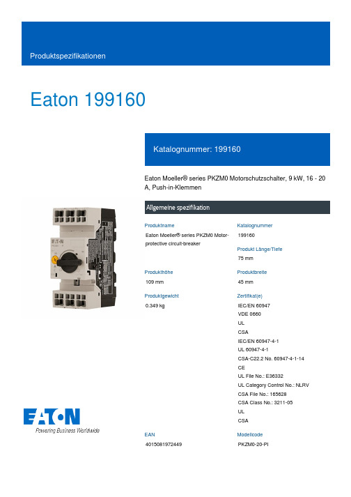
Eaton 199160Eaton Moeller® series PKZM0 Motorschutzschalter, 9 kW, 16 - 20 A, Push-in-KlemmenAllgemeine spezifikationEaton Moeller® series PKZM0 Motor-protective circuit-breaker19916075 mm109 mm 45 mm 0.349 kgIEC/EN 60947 VDE 0660 UL CSAIEC/EN 60947-4-1 UL 60947-4-1CSA-C22.2 No. 60947-4-1-14 CEUL File No.: E36332UL Category Control No.: NLRV CSA File No.: 165628 CSA Class No.: 3211-05 UL CSA4015081972449PKZM0-20-PIProduktnameKatalognummer Produkt Länge/Tiefe Produkthöhe Produktbreite Produktgewicht Zertifikat(e)EANModellcodeDrehknopfPhasenausfallempfindlichkeit (gemäß IEC/EN 60947-4-1, VDE 0660 Teil 102)MotorschutzPhasenausfallempfindlich3-polig 100.000 Schaltvorgänge100.000 SchaltvorgängeHutschienenmontage optionalAufschnappbar auf Hutschiene IEC/EN 60715 mit 7,5 oder 15 mm Höhe.40 Schaltspiele/hIII3MotorschutzschalterFinger- und handrückensicher, Berührungsschutz bei senkrechter Betätigung von vorne (EN 50274)6000 V AC25 g, Mechanisch, entsprechend IEC/EN 60068-2-27, Halbsinusstoß 10 msAuch Motoren mit Effizienzklasse IE3Nebenstromkreis: Manueller Typ E bei Einsatz mit Klemme, oder geeignet für Gruppeninstallationen, (UL/CSA)≤ 0,25 %/K, Restfehler für T > 40°-25 - 55 °C, Arbeitsbereich-5 - 40 °C gemäß IEC/EN 60947, VDE 0660Motorstarterkombinationen Typ MSC…Stellgliedtyp Merkmale Funktionen Polzahl Lebensdauer, elektrischLebensdauer, mechanisch MontagemethodeEinbaulageBetriebsfrequenzÜberspannungskategorie VerschmutzungsgradProduktkategorieSchutzBemessungsstoßspannungsfestigkeit (Uimp) SchockfestigkeitGeeignet fürTemperaturkompensationVerwendet mitMax. 2000 m-25 °C55 °C25 °C40 °C40 °C80 °CFeuchte Wärme, zyklisch, nach IEC 60068-2-30 Feuchte Wärme, konstant, nach IEC 60068-2-781 x (1 - 6) mm²18 - 812 mm50 Hz60 Hz20 A5.5 kW9 kW690 V690 V20 A18 kA, 240 V, SCCR (UL/CSA) mit Leistungsschütz DILM25 18 kA, 480 Y/277 V, SCCR (UL/CSA) mit Leistungsschütz DILM25310 A, Irm, Einstellbereich max.± 20% Toleranz, AuslöserblöckeGrundgerät befestigt 15,5 x lu, Auslöserblöcke 1.5 HP 5 HP 3 HP 15 HPHöheUmgebungsbetriebstemperatur – min Umgebungsbetriebstemperatur – max Umgebungsbetriebstemperatur (gekapselt) – min Umgebungsbetriebstemperatur (gekapselt) – max Umgebungstemperatur Lagerung - min Umgebungstemperatur Lagerung - max Klimafestigkeit Anschlusskapazität (feindrähtig)Anschlusskapazität (ein-/mehrdrähtig AWG)Abisolierlänge (Hauptleiter)Bemessungsfrequenz - minBemessungsfrequenz - max Bemessungsbetriebsstrom (Ie) Bemessungsbetriebsleistung bei AC-3, 220/230 V, 50 Hz Bemessungsbetriebsleistung bei AC-3, 380/400 V, 50 Hz Bemessungsbetriebsspannung (Ue) - min Bemessungsbetriebsspannung (Ue) - max Bemessungsdauerstrom (Iu)Bemessungskurzschlussstrom (Typ E) Kurzschlussauslöser Zugeor. Motorleist. b. 115/120 V, 60 Hz, 1-phasig Zugeordnete Motorleistung bei 200/208 V, 60 Hz, 3-phasig Zugeordnete Motorleistung bei 230/240 V, 60 Hz, 1-phasig Zugeordnete Motorleistung bei 575/600 V, 60 Hzm 3-phasigPush-In Klemmen020 A20 AÜberlastauslöser: Auslöseklasse 10 A 5.82 W0 W0 W0 WAnforderungen der Produktnorm sind erfüllt.Anforderungen der Produktnorm sind erfüllt.Anforderungen der Produktnorm sind erfüllt.Anforderungen der Produktnorm sind erfüllt.Anforderungen der Produktnorm sind erfüllt.Unzutreffend, da die gesamten Schaltgeräte überprüft werden müssen.Unzutreffend, da die gesamten Schaltgeräte überprüft werden müssen.Anforderungen der Produktnorm sind erfüllt.Verbindung Anzahl der Hilfskontakte (Wechsler)Anzahl der Hilfskontakte (Öffner)Anzahl Hilfskontakte (Schließer)Überlastauslösestromeinstellung - min Überlastauslösestromeinstellung - max Auslösecharakteristik Geräteverlustleistung, stromabhängig pvid Verlustleistungskapazität PdissVerlustleistung pro Pol, stromabhängig, PvidStatische Verlustleistung, stromunabhängig PVS10.2.2 Korrosionsbeständigkeit10.2.3.1 Wärmebeständigkeit von Umhüllung10.2.3.2 Widerstandsfähigkeit Isolierstoffe gewöhnliche Wärme 10.2.3.3 Widerst. Isolierstoffe abnorm. Wärme/Feuer durch int. elektr. Auswirk.10.2.4 Beständigkeit gegen UV-Strahlung10.2.5 Heben10.2.6 Schlagprüfung10.2.7 BeschriftungenUnzutreffend, da die gesamten Schaltgeräte überprüft werden müssen.Anforderungen der Produktnorm sind erfüllt.Unzutreffend, da die gesamten Schaltgeräte überprüft werden müssen.Unzutreffend, da die gesamten Schaltgeräte überprüft werden müssen.Liegt in der Verantwortung des Schaltanlagenbauers.Liegt in der Verantwortung des Schaltanlagenbauers.Liegt in der Verantwortung des Schaltanlagenbauers.Liegt in der Verantwortung des Schaltanlagenbauers.Liegt in der Verantwortung des Schaltanlagenbauers.Die Erwärmungsberechnung liegt in der Verantwortung des Schaltanlagenbauers. Eaton stellt Verlustleistungsdaten der Geräte bereit.Liegt in der Verantwortung des Schaltanlagenbauers. Die Spezifikationen für die Schaltgeräte müssen beachtet werden.Liegt in der Verantwortung des Schaltanlagenbauers. Die Spezifikationen für die Schaltgeräte müssen beachtet werden.Das Gerät erfüllt die Anforderungen, wenn die Informationen in der Montageanweisung (IL) beachtet werden.DA-DC-00004889.pdfDA-DC-00004919.pdfETN.PKZM0-20-PI.edzIL122024ZUWIN-WIN mit Push-in-TechnikProduktübersicht für den Maschinenbau Sortimentskatalog Motoren schalten und schützenpkzm0_pi.stpmotorschutzschalter_bis_32a_pi.dwgeaton-manual-motor-starters-pkz-dimensions.epseaton-manual-motor-starters-pkz-dimensions-002.eps eaton-manual-motor-starters-pkzm-pkzm0-dimensions.eps 121X042121X00210.3 Schutzart von Baugruppen10.4 Luft- und Kriechstrecken10.5 Schutz gegen elektrischen Schlag10.6 Einbau von Betriebsmitteln10.7 Innere Stromkreise und Verbindungen10.8 Anschlüsse für von außen eingeführte Leiter 10.9.2 Betriebsfrequente Spannungsfestigkeit 10.9.3 Stoßspannungsfestigkeit10.9.4 Prüfung von Umhüllungen aus Isolierstoff 10.10 Erwärmung10.11 Kurzschlussfestigkeit10.12 Elektromagnetische Verträglichkeit10.13 Mechanische Funktion Declarations of conformity eCAD model Installationsanleitung Installationsvideos KatalogemCAD model ZeichnungenEaton Konzern plc Eaton-Haus30 Pembroke-Straße Dublin 4, Irland © 2023 Eaton. Alle Rechte vorbehalten. Eaton ist eine eingetrageneMarke.Alle anderen Warenzeichen sindEigentum ihrer jeweiligenBesitzer./socialmedia。

——RoundTACT Switch TMSharp FeelingSoft Feeling Snap-in TypeSurface Mount TypeRadial TypeTACT Switch TM / Soldering ConditionsTemperature profile■Condition for ReflowAvailable for Surface Mount Type.180150260˚C max. 3s max.230˚CTim e120s max. pre-heatin g3 to 4min.Time inside soldering equipmentTemperature (˚C )40s max.1. Prevent flux penetration from the top side of the TACT Switch TM .2. Switch terminals and a PC board should not be coated with flux prior to soldering.3. The second soldering should be done after the switch is stable with normal temperature.4. Use the flux with a specific gravity of min 0.81. (EC-19S-8 by TAMURA CORPORATION, or equivalents.)Notes1. Please confirm the specifications of our product for the detailed condition.2. Soldering conditions differ depending on reflow soldering machines. Prior verification of soldering condition is highly recommended.Notes■Conditions for Auto-dipAvailable for Snap-in Type and Radial Type.Items ConditionFlux built-upMounting surface should not be exposed to fluxPreheating temperature Ambient temperature of the soldered surface of PC board. 100℃ max.Preheating time 60s max.Soldering temperature 260℃ max.Duration of immersion 5s max.Number of soldering2times max.SKHH SeriesItems ConditionFlux built-up Mounting surface should not be exposed to flux Preheating temperatureAmbient temperature of the soldered surface of PC board. 110℃ max.Preheating time 60s max.Soldering temperature 260℃ max.Duration of immersion 5s max.Number of soldering2times max.SKHL Top Push Type, SKQJ SeriesItems ConditionFlux built-up Mounting surface should not be exposed to flux Preheating temperatureAmbient temperature of the soldered surface of PC board. 100℃ max.Preheating time 45s max.Soldering temperature 255℃ max.Duration of immersion 5s max.Number of soldering2times max.■Manual SolderingItemsConditionSoldering temperature 350℃ max.Duration of soldering 3s max.Capacity of soldering iron60W max.SKHH, SKHW SeriesItemsConditionSoldering temperature 360℃ max.Duration of soldering 3s max.Capacity of soldering iron60W max.SKTD, SKTG, SKQJ, SKSN SeriesItemsConditionSoldering temperature 350℃ max.Duration of soldering 3s max.Capacity of soldering iron20W max.。

IT-180ABS/IT-180ATCHigh Tg, Low CTE, Multifunctional Filled Epoxy Resin and Phenolic-Cured Laminate & PrepregIT-180A is an advanced high Tg (175℃ by DSC) multifunctional filled epoxy with low CTE, high thermal reliability and CAF resistance. It’s design for high layer PCB and can pass 260℃ Lead free assembly and sequential lamination process.Key Features =============================== Advanced High Tg Resin TechnologyIndustrial standard material with high Tg (175℃ by DSC) multifunctional filled epoxy resin and excellent thermal reliability. Lead-Free Assembly CompatibleRoHS compliant and suitable for high thermal reliability needs, and Lead free assemblies with a maximum reflow temperature of 260℃. Friendly Processing and CAF ResistanceFriendly PCB process like high Tg FR4. Users can short the learning curve when using this material.CAF ResistanceLow thermal expansion coefficient (CTE) helps to excellent thermal reliability and CAF resistance providing long-term reliability for industrial boards and automobile application.Available in Variety of ConstructionsAvailable in a various of constructions, copper weights and glass styles, including standard(HTE), RTF and VLP copper foil. ApplicationsMultilayer and High Layer PCB AutomobileBackplanesServers and Networking TelecommunicationsData StorageHeavy Copper ApplicationIndustrial ApprovalUL 94 V-0IPC-4101C Spec / 99/ 101/ 126 RoHS CompliantGlobal AvailabilityITEQ Laminate/ Prepreg : IT-180ATC / IT-180ABS IPC-4101C Spec / 99 / 101 / 126LAMINATE( IT-180ATC)Thickness<0.50 mm[0.0197 in] Thickness≧0.50 mm[0.0197 in] Units Test MethodPropertyTypical Value Spec Typical Value Spec Metric(English) IPC-TM-650 (or as noted)Peel Strength, minimumA. Low profile copper foil and very low profilecopper foil - all copper weights > 17µm[0.669 mil]B. Standard profile copper foil1.After Thermal Stress2.At 125°C [257 F]3.After Process Solutions 0.88 (5.0)1.23 (7.0)1.05 (6.0)1.05 (6.0)0.70 (4.00)0.80 (4.57)0.70 (4.00)0.55 (3.14)0.88 (5.0)1.40 (8.0)1.23 (7.0)1.23 (7.0)0.70 (4.00)1.05 (6.00)0.70 (4.00)0.80 (4.57)N/mm(lb/inch)2.4.82.4.8.22.4.8.3Volume Resistivity, minimumA. C-96/35/90B. After moisture resistanceC. At elevated temperature E-24/125 3.0x10¹⁰--5.0x1010106--103--3.0x10101.0x1010--104103MΩ-cm 2.5.17.1Surface Resistivity, minimumA. C-96/35/90B. After moisture resistanceC. At elevated temperature E-24/125 3.0x10¹⁰--4.0x1010104--103--3.0x10104.0x1010--104103MΩ 2.5.17.1Moisture Absorption, maximum - 0.12 0.8 % 2.6.2.1 Dielectric Breakdown, minimum - - 60 40 kV 2.5.6 Permittivity (Dk, 50% resin content)(Laminate & Laminated Prepreg)A. 1MHzB. 1GHzC. 2GHzD. 5GHzE. 10GHz 4.44.44.24.14.05.44.44.44.34.14.15.4 -- 2.5.5.92.5.5.13Loss Tangent (Df, 50% resin content)(Laminate & Laminated Prepreg)A. 1MHzB. 1GHzC. 2GHzD. 5GHzE. 10GHz 0.0150.0150.0150.0160.0170.0350.0140.0150.0150.0160.0160.035 -- 2.5.5.92.5.5.13Flexural Strength, minimumA. Length directionB. Cross direction --------580(84,300)450(65,400)415 (60,190)345 (50,140)N/mm2(lb/in2) 2.4.4Arc Resistance, minimum 125 60 125 60 s 2.5.1Thermal Stress 10 s at 288°C [550.4F],minimumA. UnetchedB. Etched PassPassPass VisualPass VisualPassPassPass VisualPass VisualRating 2.4.13.1Electric Strength, minimum(Laminate & Laminated Prepreg) 45 30 -- -- kV/mm 2.5.6.2 Flammability,(Laminate & Laminated Prepreg) V-0 V-0 V-0 V-0 Rating UL94 Glass Transition Temperature(DSC) 175 170 minimum 175 170 minimum ˚C 2.4.25 Decomposition Temperature -- -- 345 340 minimum ˚C 2.4.24.6(5% wt loss) X/Y Axis CTE (40℃ to 125℃) -- -- 10-13 -- PPM/˚C 2.4.24Z-Axis CTEA. Alpha 1B. Alpha 2C. 50 to 260 Degrees C ------------452102.760 maximum300 maximum3.0 maximumPPM/˚CPPM/˚C%2.4.24Thermal ResistanceA. T260B. T288 -------->60>3030 minimum15 minimumMinutesMinutes2.4.24.1CAF Resistance -- -- Pass AABUS Pass/Fail 2.6.25 Comparative Tracking Index(CTI) -- -- 175~250V -- V UL-746 The above data and fabrication guide provide designers and PCB shop for their reference. We believe that these information are accurate, however, the data may vary depend on the test methods and specification used. The actual sales of the product should be according to specification in the agreement between ITEQ and its customer. ITEQ reserves the right to revise its data at any time without notice and maintain the bestinformation available to users.IT-180ABS/IT-180ATCHigh Tg, Low CTE, Multifunctional Filled Epoxy Resin and Phenolic-Cured Laminate & Prepreg---------------------------------------------------------------------------------------------------------------------------------------------- Process Guideline1. Prepreg Handling & Storage(1) Shelf life is at least 3 months when prepreg stored in a cool dry environment (Temperature: <20 ℃ and Humidity: <50%).(2) Prepreg exposed to humidity should be resealed to minimize moisture absorption.(3)Prepreg should be stored in controlled environment for 12 hours prior to use.(4)Prepreg supplied in rolls or panels should be stored horizontally. To avoid damage, no stacking is recommended.2. Laminate Handling & Storage(1) Laminates should be stored in a dry environment(2) Laminate should always be stored flat3. Inner Layer Process(1)First around must be taken to determine suitable parameters (such as dimensional compensation, etc) before mass production.(2) Inner layers should be baked for at least 40 min at 120 ℃ after black or brown oxides treatment.Note: The material temperature is not allowed to >195 ℃ in lamination process if brown oxide treatment is used.4. Lamination Overview(1)Stacks must be prepared in lay-up room to avoid moisture absorption.(2) Recommended pressure ranges should be as follows:Hydraulic/350~400psiVacuum Hydraulic/300~400psi(3) For Lien Chieh press, heating rate is 1.3~1.8℃/min from 80℃ to 140℃, and for Burkle press, the heating rate is 1.5~3.0℃/min from 80℃to 140℃. Cooling rate below 3℃/min is recommended.(4) When the board temperature reaches 180℃ during the pressing process, the lamination process should be kept for at least 60 minutes.5. DrillingDrilling parameters are mainly dependent on the hole size, layer thickness, layer number, copper thickness, and stack height. The following drilling parameters are for reference only. Typical drilling parameters for 0.4~1.0 mm drills are as follows:Spindle speed: 45~105 KRPM Feed rate: 50~150 IPMRetract rate: 500~1000 IPM Max. hit count: <1000 HITSStack height: ≤2pnls(2~6layers), 1pnl(≥8layers) Entry Material: 0.2mm AluminumBack-up Material: 1.5mm Phenolic laminate Drilling Machine: Hitachi ND-6L210EBaking condition: After Drilling: 170 °C /2 hours6. DesmearThe following desmear parameters are for reference only:Horizontal (JETCHEM)Swell : 75℃ for 100 s Mn+7 : 55-65 g/ l at 85℃ for 180sVertical (ROHMHAAS)Swell : 65℃ for 365 s Mn+7 : 65-75 g/ l at 75℃ for 750sNormally, the typical parameters used to desmear FR-4 product may not produce optimum hole topography for IT-180A. One should consult with your chemical supplier to optimize your desmear condition, e.g. desmear two times or adjust other parameters, etc.。

z 赛瓦特发电机组的设计、生产和测试完全符合GB/T2820-97的国家标准,广泛应用于工业、矿山、建筑、通讯等领域,甚至在极为恶劣的环境下,也能提供非常可靠的电力;z 赛瓦特独创设计的内置多级减振系统,能有效的消除机组运行时的振动,使控制系统及电气元件受到更好的保护;z 配备东风康明斯发动机,技术先进,性能可靠,高燃烧效率及低燃油消耗,持续运行时间长,具有超长的工作 ,可在各种环境下稳定运行,且保养和维护方便;z 配备STAMFORD 发电机,承受瞬间加载时电压、频率恢复迅速,非线性负载下的波形畸变率极小,附加PMG 后起动电动机的能力更强;z 标准配制PCRC230控制系统,具有高性价比和应用灵活的控制保护功能,能适应各种气候条件。
直观的LCD 数字显示发电机组各项参数,使用户在操作和维护过程中更加简便。
康明斯6LT 系列柴油发动机,中美合资东风康明斯公司生产。
额定转速1500RPM ,四冲程、直列、风扇水箱闭式冷却,符合ISO3046标准。
z 高可靠性,低排放,起动性能好 z 24V 直流电启动马达 z 柴油机驱动充电发电机 z 电子调速z 废气涡轮增压z 燃油、机油、空气滤清器 z SAE 标准飞轮壳 世界一流品牌斯坦福同步交流发电机,英资无锡新时代公司生产。
符合GB755, BS5000, VDE0530, IEC34-1, CSA22.2, AS2359标准。
z 无刷自励发电机系统,在各种情况下均可提供可靠励磁;z 标准的2/3节距绕组,有效抑制过多的中线电流; z 绝缘等级:H ,防护等级:IP23;z 稳态电压调整率:≤±1.0%; z 电话干扰:THF < 2%, TIF < 50;z 与其他品牌发电机相比,斯坦福发电机效率最高。
赛瓦特标准配置PCRC230控制系统,采用丹麦DEIF 品牌GC-1F 控制模块,为基于微处理技术、包含所有功能的柴油发电机保护控制器。
GED1963系列——低压差线性稳压器1.产品特性◆输出电流:1.5A◆压差电压:300mV◆低噪声:40μV RMS◆1mA的静态电流◆无需保护二极管◆固定输出电压:1.5V、1.8V、2.5V、3.3V◆可调输出电压:1.33V to 20V◆电池反接保护◆无反向电流◆过热保护◆塑封3-Lead SOT-223,8-Lead SO◆可兼容LT1963系列产品◆工作温度范围:-40℃~125℃◆质量等级:工业级(I)2.产品应用◆提供逻辑电源◆开关电源的后置稳压器3.产品概述GED1963电路是低压差稳压器,用于产生一个稳定电压源,固定输出 1.5V、1.8V、2.5V、3.3V,可调输出电压 1.33V-20V,压差电压为300mV时可提供 1.5A的电流,静态工作电流小于1mA。
GED1963可使用最小10uF的输出电容,芯片具有电池反接保护、过流保护、过热保护和电流反接保护等特性。
GED1963采用SOT-223和8-Lead SO塑料封装。
4.典型应用图4-1 GED1963系列的典型应用电路C1为输入电容,一般使用10uF陶瓷电容,C2为输出电容,一般使用10uF钽电容,若使用陶瓷电容需要增加相应的ESR电阻,详见9.3节。
5.绝对最大额定值IN脚电压……………………………………………………………………………±20VOUT脚电压…………………………………………………………………………-0.6V,20V输入输出压差…………………………………………………………………………±20VADJ脚电压…………………………………………………………………………±7VSHDN脚电压………………………………………………………………………±20V工作结温范围(注2)………………………………………………………………-40℃~+125℃储存温度范围…………………………………………………………………………-65℃~+150℃引脚温度(焊接,10秒)……………………………………………………………300℃注1:列表中数值是绝对最大额定值,任何超过这些值的情况,可能对器件造成永久损害。
General DescriptionThe MAX1963/MAX1976 low-dropout linear regulators operate from a +1.62V to +3.6V supply and deliver a guaranteed 300mA continuous load current with a low 100mV dropout. The high-accuracy (±0.5%) output voltage is preset to an internally trimmed voltage in the +0.75V to +3.0V range. An active-low, open-drain reset output remains asserted for at least 2.2ms (MAX1963)or 70ms (MAX1976) after the output voltage reaches regulation. These devices are offered in 6-pin thin SOT23 and 6-pin 3mm x 3mm thin DFN packages.An internal PMOS pass transistor allows the low supply current to remain independent of load and dropout volt-age, making these devices ideal for portable battery-pow-ered equipment such as personal digital assistants (PDAs), cell phones, cordless phones, and notebook com-puters. Other features include logic-controlled shutdown,short-circuit protection, and thermal-overload protection.ApplicationsNotebook Computers Cellular and PCS Telephones Personal Digital Assistants (PDAs)Hand-Held Computers Digital Cameras PCMCIA Cards CD and MP3 PlayersFeatures♦Low 1.62V Minimum Input Voltage ♦Guaranteed 300mA Output Current ♦±2.5% Accuracy Over Load/Line/Temp ♦Low 100mV Dropout at 300mA Load ♦2.2ms (MAX1963) or 70ms (MAX1976) RESET Output Flag ♦Supply Current Independent of Load and Dropout Voltage ♦Logic-Controlled Shutdown♦Thermal-Overload and Short-Circuit Protection ♦Preset Output Voltages (0.75V to 3.0V)♦Tiny 6-Pin Thin SOT23 Package (<1.1mm High)♦Thin 6-Pin TDFN Package (<0.8mm High)MAX1963/MAX1976Low-Input-Voltage, 300mA LDO Regulatorswith RESET in SOT and TDFN________________________________________________________________Maxim Integrated Products1Ordering Information19-3040; Rev 2; 5/07For pricing, delivery, and ordering information,please contact Maxim/Dallas Direct!at 1-888-629-4642, or visit Maxim’s website at .Pin Configurations*Insert the desired three-digit suffix (see the Selector Guide) into the blanks to complete the part number. Contact the factory for other output voltages.Selector Guide appears at end of data sheet.Typical Operating CircuitM A X 1963/M A X 1976Low-Input-Voltage, 300mA LDO Regulators with RESET in SOT and TDFN 2_______________________________________________________________________________________ABSOLUTE MAXIMUM RATINGSELECTRICAL CHARACTERISTICSStresses beyond those listed under “Absolute Maximum Ratings” may cause permanent damage to the device. These are stress ratings only, and functional operation of the device at these or any other conditions beyond those indicated in the operational sections of the specifications is not implied. Exposure to absolute maximum rating conditions for extended periods may affect device reliability.IN, SHDN , RESET to GND.....................................-0.3V to +4.0V OUT to GND ................................................-0.3V to (V IN + 0.3V)Output Short-Circuit Duration.....................................Continuous Continuous Power Dissipation (T A = +70°C)6-Pin SOT23 (derate 9.1mW/°C above +70°C)............727mW 6-Pin TDFN (derate 24.4mW/°C above +70°C).........1951mWOperating Temperature Range ...........................-40°C to +85°C Junction Temperature.....................................................+150°C Storage Temperature Range.............................-65°C to +150°C Lead Temperature (soldering, 10s).................................+300°CMAX1963/MAX1976Low-Input-Voltage, 300mA LDO Regulatorswith RESET in SOT and TDFN_______________________________________________________________________________________3Note 2:The dropout voltage is defined as V IN - V OUT , when V OUT is 4% lower than the value of V OUT when V IN = V OUT + 0.5V.Typical Operating Characteristics(V IN = (V OUT + 0.5V) or 1.8V, whichever is greater; SHDN = IN, C IN = 1µF, C OUT = 4.7µF, T A = +25°C, unless otherwise noted.)OUTPUT VOLTAGE ACCURACYvs. LOAD CURRENTLOAD CURRENT (mA)O U T P U T V O L T A G E AC C U R A C Y (%)25020015010050-0.10.10.2-0.2300OUTPUT VOLTAGE ACCURACYvs. INPUT VOLTAGEINPUT VOLTAGE (V)O U T P U T V O L T A G E A C C U R A C Y (%)3.02.62.21.8-0.250.250.50-0.501.43.4OUTPUT VOLTAGE ACCURACYvs. TEMPERATURETEMPERATURE (°C)O U T P U T V O L T A G E A C C U R A C Y (%)603510-15-1.0-0.500.51.01.5-1.5-4085ELECTRICAL CHARACTERISTICS (continued)(V IN = (V OUT + 0.5V) or 1.8V, whichever is greater; SHDN = IN, C IN = 1µF, C OUT = 4.7µF, T A = -40°C to +85°C, unless otherwise noted. Typical values are at T = +25°C.) (Note 1)M A X 1963/M A X 1976Low-Input-Voltage, 300mA LDO Regulators with RESET in SOT and TDFN 4_______________________________________________________________________________________GROUND-PIN CURRENT vs. LOAD CURRENTLOAD CURRENT (mA)G R O U N D -P I N C U R R E N T (μA )1001100.1708090100110120600.011000GROUND-PIN CURRENT vs. INPUT VOLTAGEINPUT VOLTAGE (V)G R O U N D -P I N C U RR E N T (μA )3.22.82.42.01.62040608010012001.23.6GROUND-PIN CURRENT vs. TEMPERATURETEMPERATURE (°C)G R O U N D -P I N C U R R E N T (μA )604020-206070809010011012050-4080DROPOUT VOLTAGE vs. LOAD CURRENTLOAD CURRENT (mA)V D R O P O U T (m V )250200150100504020608010012000300POWER-SUPPLY REJECTION RATIOvs. FREQUENCYFREQUENCY (kHz)P S R R (d B )10010110203040506070800.11000LINE-TRANSIENT RESPONSEMAX1963/76 toc0940μs/divV IN 500mV/div1.5V 10mV/div AC-COUPLEDV OUT3.5VTypical Operating Characteristics (continued)(V IN = (V OUT + 0.5V) or 1.8V, whichever is greater; SHDN = IN, C IN = 1µF, C OUT = 4.7µF, T A = +25°C, unless otherwise noted.)LINE-TRANSIENT RESPONSENEAR DROPOUTMAX1963/76 toc1040μs/divV IN 500mV/div1.5V 10mV/div AC-COUPLEDV OUT1.8VMAX1963/MAX1976Low-Input-Voltage, 300mA LDO Regulatorswith RESET in SOT and TDFN_______________________________________________________________________________________5LOAD-TRANSIENT RESPONSEMAX1963/76 toc1120μs/div200mA/div20mV/div AC-COUPLED200mA V OUTI OUT 20mAV IN = 3.6V V OUT = 1.5VLOAD-TRANSIENT RESPONSENEAR DROPOUTMAX1963/76 toc1220μs/div200mA/div20mV/div AC-COUPLED200mA V OUTV IN = 1.8V V OUT = 1.5VI OUT 20mATypical Operating Characteristics (continued)(V IN = (V OUT + 0.5V) or 1.8V, whichever is greater; SHDN = IN, C IN = 1µF, C OUT = 4.7µF, T A = +25°C, unless otherwise noted.)SHUTDOWN RESPONSEMAX1963/76 toc13100μs/div 1V/div500mV/divV OUTV SHDNMAX1963/76 toc1440ms/div1V/div1V/div1V/divV OUT000V SHDNV RESETMAX1976ASHUTDOWN/RESET RESPONSEMAX1963/76 toc15200ms/div2V/div1V/div1V/divV OUTV IN000V MAX1976ALINE/RESET RESPONSEM A X 1963/M A X 1976Detailed DescriptionThe MAX1963/MAX1976 are low-dropout, high-accuracy,low-quiescent-current linear regulators designed primarily for battery-powered applications. These devices supply loads up to 300mA and are available with preset output voltages from +0.75V to +3.0V. As illustrated in Figure 1,the MAX1963/MAX1976 consist of a reference, an error amplifier, a P-channel pass transistor, an internal feed-back voltage-divider, and a power-good comparator.The reference is connected to the error amplifier, which compares this reference with the feedback voltage and amplifies the difference. If the feedback voltage is lower than the reference voltage, the pass-transistor gate is pulled lower, which allows more current to pass to the output and increases the output voltage. If the feedback voltage is too high, the pass-transistor gate is pulled up, allowing less current to pass to the output.Low-Input-Voltage, 300mA LDO Regulators with RESET in SOT and TDFN 6_______________________________________________________________________________________Pin DescriptionFigure 1. Functional DiagramInternal P-Channel Pass Transistor The MAX1963/MAX1976 feature a 0.33Ω(R DS(ON)) P-channel MOSF ET pass transistor. Unlike similar designs using PNP pass transistors, P-channel MOSFETs require no base drive, which reduces quies-cent current. PNP-based regulators also waste consid-erable current in dropout when the pass transistor saturates and use high base-drive currents under large loads. The MAX1963/MAX1976 do not suffer from these problems and consume only 90µA (typ) of quiescent current under heavy loads, as well as in dropout.Shutdown Pull SHDN low to enter shutdown. During shutdown, the output is disconnected from the input, an internal 1.5kΩresistor pulls OUT to GND, RESET is actively pulled low, and the supply current drops below 1µA.RESET Output The MAX1963/MAX1976 microprocessor (µP) supervisory circuitry asserts a guaranteed logic-low reset during power-up, power-down, and brownout conditions down to +1V. RESET asserts when V OUT is below the reset threshold and remains asserted for at least t RP after V OUT rises above the reset threshold of regulation.Current Limit The MAX1963/MAX1976monitor and control the pass transistor’s gate voltage, limiting the output current to 450mA (min). If the output exceeds I LIM, the MAX1963/ MAX1976 output voltage drops.Thermal-Overload Protection Thermal-overload protection limits total power dissipa-tion in the MAX1963/MAX1976. When the junction tem-perature exceeds T J= +165°C, a thermal sensor turns off the pass transistor, allowing the IC to cool. The ther-mal sensor turns the pass transistor on again after the junction temperature cools by 15°C, resulting in a pulsed output during continuous thermal-overload con-ditions. Thermal-overload protection safeguards the MAX1963/MAX1976 in the event of fault conditions. For continuous operation, do not exceed the absolute maxi-mum junction-temperature rating of T J= +150°C.Operating Region and Power Dissipation The MAX1963/MAX1976 maximum power dissipation depends on the thermal resistance of the IC package and circuit board, the temperature difference between the die junction and ambient air, and the rate of airflow. The power dissipated in the device is P = I OUT✕(V IN-V OUT). The maximum allowed power dissipation is:P MAX= (T J(MAX)- T A) / (θJC+ θCA)between the MAX1963/MAX1976 die junction and the surrounding air, θJC is the thermal resistance of the junction to the case, and θCA is the thermal resistancefrom the case through the PC board, copper traces,and other materials to the surrounding air. F or best heatsinking, expand the copper connected to the exposed paddle or GND.MAX1963/MAX1976Low-Input-Voltage, 300mA LDO Regulatorswith RESET in SOT and TDFN _______________________________________________________________________________________7M A X 1963/M A X 1976The MAX1963/MAX1976 deliver up to 300mA and oper-ate with an input voltage up to +3.6V. However, when using the 6-pin SOT23 version, high output currents can only be sustained when the input-output differential voltage is less than 2V, as shown in Figure 2.The maximum allowed power dissipation for the 6-pin TDFN is 1.951W at T A = +70°C. Figure 3 shows that the maximum input-output differential voltage is not limited by the TDFN package power rating.Applications InformationCapacitor Selection andRegulator StabilityCapacitors are required at the MAX1963/MAX1976input and output for stable operation over the full tem-perature range and with load currents up to 300mA.Connect a 1µF ceramic capacitor between IN and GND and a 4.7µF low-ESR ceramic capacitor between OUT and GND. The input capacitor (C IN ) lowers the source impedance of the input supply. Use larger output capacitors to reduce noise and improve load-transient response, stability, and power-supply rejection.The output capacitor’s equivalent series resistance (ESR) affects stability and output noise. Use output capacitors with an ESR of 30m Ωor less to ensure sta-bility and optimize transient response. Surface-mount ceramic capacitors have very low ESR and are com-monly available in values up to 10µF. Connect C IN and C OUT as close to the MAX1963/MAX1976 as possible to minimize the impact of PC board trace inductance.Noise, PSRR, and Transient ResponseThe MAX1963/MAX1976 are designed to operate with low dropout voltages and low quiescent currents in bat-tery-powered systems while still maintaining good noise, transient response, and AC rejection. See the T ypical Operating Characteristics for a plot of Power-Supply Rejection Ratio (PSRR) versus F requency.When operating from noisy sources, improved supply-noise rejection and transient response can be achieved by increasing the values of the input and output bypass capacitors and through passive filtering techniques.The MAX1963/MAX1976 load-transient response (see the Typical Operating Characteristics ) shows two com-ponents of the output response: a near-zero DC shift from the output impedance due to the load-current change, and the transient response. A typical transientresponse for a step change in the load current from 20mA to 200mA is 20mV. Increasing the output capacitor’s value and decreasing the ESR attenuates the overshoot.Input-Output (Dropout) VoltageA regulator’s minimum input-output voltage difference (dropout voltage) determines the lowest usable supply voltage. In battery-powered systems, this determines the useful end-of-life battery voltage. Because the MAX1963/MAX1976 use a P-channel MOSFET pass tran-sistor, the dropout voltage is a function of drain-to-source on-resistance (R DS(ON) = 0.33Ω) multiplied by the load current (see the Typical Operating Characteristics ).V DROPOUT = V IN - V OUT = 0.33Ω✕I OUTThe MAX1963/MAX1976 ground current reduces to 70µA in dropout.Low-Input-Voltage, 300mA LDO Regulators with RESET in SOT and TDFN 8_______________________________________________________________________________________Chip InformationTRANSISTOR COUNT: 2556PROCESS: BiCMOSSelector Guide(Note: Standard voltage options, shown in bold , are available.Contact the factory for other output voltages between 1.5V and 4.5V. Minimum order quantity is 15,000 units.)MAX1963/MAX1976Low-Input-Voltage, 300mA LDO Regulatorswith RESET in SOT and TDFN_______________________________________________________________________________________9Package Information(The package drawing(s) in this data sheet may not reflect the most current specifications. For the latest package outline information,go to /packages .)M A X 1963/M A X 1976Low-Input-Voltage, 300mA LDO Regulators with RESET in SOT and TDFN 10______________________________________________________________________________________Package Information (continued)(The package drawing(s) in this data sheet may not reflect the most current specifications. For the latest package outline information,go to /packages.)MAX1963/MAX1976Low-Input-Voltage, 300mA LDO Regulatorswith RESET in SOT and TDFN______________________________________________________________________________________11Package Information (continued)(The package drawing(s) in this data sheet may not reflect the most current specifications. For the latest package outline information,go to /packages .)M A X 1963/M A X 1976Low-Input-Voltage, 300mA LDO Regulators with RESET in SOT and TDFN Maxim cannot assume responsibility for use of any circuitry other than circuitry entirely embodied in a Maxim product. No circuit patent licenses are implied. Maxim reserves the right to change the circuitry and specifications without notice at any time.12____________________Maxim Integrated Products, 120 San Gabriel Drive, Sunnyvale, CA 94086 408-737-7600©2007 Maxim Integrated Productsis a registered trademark of Maxim Integrated Products, Inc.Package Information (continued)(The package drawing(s) in this data sheet may not reflect the most current specifications. For the latest package outline information,go to /packages .)Revision HistoryPages changed at Rev 2: 1, 2, 9–12。