第三章316温度传感器-1
- 格式:ppt
- 大小:2.88 MB
- 文档页数:143
温度传感器的功能特点介绍传感器常见问题解决方法温度传感器是指能感受温度并转换成可用输出信号的传感器。
温度传感器是温度测量仪表的核心部分,品种繁多。
按测量方式可分为接触式和非接触式两大类,依照传温度传感器是指能感受温度并转换成可用输出信号的传感器。
温度传感器是温度测量仪表的核心部分,品种繁多。
按测量方式可分为接触式和非接触式两大类,依照传感器材料及电子元件特性分为热电阻和热电偶两类。
功能和特点1,检定K、E、J、N、B、S、R、T等多种型号的工作用热电偶2,检定Pt100、Pt10、Cu50、Cu100等各种工作用热电阻,玻璃液体温度计、压力式温度计、双金属温度计3,多路低电势自动转换开关,寄生电势≤0.4μV4,掌控1—4台高温炉5,温场测试:可进行检定炉、油槽、水槽、低温恒温槽的温场测试6,线制转换:可进行二线制、三线制、四线制电阻检定7,软件具有比对试验、重复性试验、温场试验等相关试验功能软件平台:8,在Windows2000/XP以上平台,全中文界面,标准Windows 操作系统,便利快捷。
可实现:a)设备自检、查线b)屏幕显示并保存控温曲线≤0.4μVc)检测数据自动采集d)自动生成符合要求的检定记录e)自动保存检定结果,且不可人工更改f)查询各种热电偶、热电阻分度表及其它帮忙g)热电偶、热电阻全部历史检定数据、控温曲线查询统计及计量的智能化管理功能简介温度传感器是比较早开发,应用广泛的一类传感器。
温度传感器的市场份额大大超过了其他的传感器。
从17世纪初人们开始利用温度进行测量。
在半导体技术的支持下,本世纪相继开发了半导体热电偶传感器、PN结温度传感器和集成温度传感器。
与之相应,依据波与物质的相互作用规律,相继开发了声学温度传感器、红外传感器和微波传感器。
温度传感器是五花八门的各种传感器中较为常用的一种,现代的温度传感器外形特别得小;这样更加让它广泛应用在生产实践的各个领域中,也为人们的生活供应了极多的便利和功能。


主题DQ200变速箱更换控制单元操作方法编号2018033涉及车型针对机电单元零件号为0AM 325 025 D(H\L\M)的DQ200变速箱发布日期2018-07-10技术背景从即日起一汽大众售后向各特许经销商提供DQ200变速箱单独的控制单元备件,可以应用于解决以下故障,无需再更换机电单元总成。
售后解决方案1. 使用ODIS诊断仪连接车辆,在变速箱控制单元中有以下任意一条故障存储器记录,就需要更换控制单元处理。
故障代码列举如下:1) P084000: 变速箱液压压力传感器1 电路中的电气故障2) P066600: 内部温度传感器1 电气故障3) P177900: 变速箱输入轴1 转速过高4) P177A00: 变速箱输入轴2 转速过高5) P072600: 发动机控制单元转速信号的信号失真6) P172F00: 换挡执行器的程传感器1 电气故障7) P173000: 换挡执行器的程传感器2 电气故障8) P173100: 换挡执行器的程传感器3 电气故障9) P173200: 换挡执行器的程传感器4 电气故障10) P173500: 离合器1 位置传感器电气故障11) P173600: 离合器2 位置传感器电气故障12) P177F00: 液压泵电机低电压13) P174A00: 分变速箱1 中的阀门3 电气故障14) P173E00: 分变速箱1 中的阀门1 电气故障15) P174C00: 分变速箱2 中的阀门1 电气故障16) P173F00: 分变速箱1 中的阀门2 电气故障17) P174D00: 分变速箱2 中的阀门2 电气故障18) P174B00: 分变速箱1 中的阀门4 电气故障19) P174E00: 分变速箱2 中的阀门3 电气故障20) P17C700: 变速箱输入转速传感器3–电路中的电气故障21) P071500: 变速箱输入转速传感器1–电路中的电气故障22) P276500: 变速箱输入转速传感器2–电路中的电气故障23) P160400: 控制单元损坏24) P056200: 电源电压过低25) P172700: 变速箱运转方向失真2. 对于新的控制单元需要软件刷新处理,具体刷新方法如下:说明:ODIS(Offboard Diagnostic Information System Service)须安装(非车载诊断信息系统服务)补丁版(产品版本)1.0.1 以及基准版(诊断数据-didb_GFS-v)2.35.11或者更高版本。
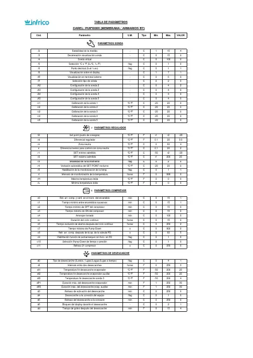
Cód.ParámetroU.M.TipoMín.Máx.VALOR/2Estabilidad de la medida -C 1154/3Deceleración visualización sonda-C 0150/4Sonda virtual-C 01000/5Selección °C o °F (0=°C, 1=°F)flag C 010/6Punto decimal (0=si 1=no)flag C 011/tI Visualización sobre el display -C 171/tE Visualización en terminal externo-C 060/P Selección tipo de sonda -C 020/A2Configuración de la sonda 2-C 042/A3Configuración de la sonda 3-C 040/A4Configuración de la sonda 4-C 040/A5Configuración de la sonda 5-C 040/c1Calibración de la sonda 1°C/°F C -20200/c2Calibración de la sonda 2°C/°F C -20200/c3Calibración de la sonda 3°C/°F C -20200/c4Calibración de la sonda 4°C/°F C -20200/c5Calibración de la sonda 5°C/°FC-2020St Set point (punto de consigna)°C/°F F r1r2-23rd Diferencial regulador°C/°F F 0.120 3.0rn Zona neutra°C/°F C 0604rr Diferencia inverso para control con zona neutra°C/°F C 0,1202r1SET mínimo admitido °C/°F C -50r2-23r2SET máximo admitido °C/°F C r120020TABLA DE PARÁMETROSCAREL: PUIFI0006 (MEMBRANA / ARMARIOS BT)/ PARÁMETROS SONDAr PARÁMETROS REGULADORr3Modalidad de funcionamientoflag C 020r4Variación automática del SET POINT nocturno °C/°F C -20200r5Habilitación de la monitorización de la temp.flag C 011rt Intervalo de monitorización de la temperaturahoras F 09990rH Máxima temperatura leída °C/°F F 000rLMínima temperatura leída°C/°FFc0Ret. arr. comp. y vent. en el mom. del encendido min C 0151c1Tiempo mínimo entre encendidos sucesivos min C 0151c2Tiempo mínimo de OFF del compresor min C 0150c3Tiempo mínimo de ON del compresormin C 0150c4Arranque forzado min C 01000cc Duración del ciclo continuohoras C 0150c6Tiempo exclusión de alarma después del ciclo continuohoras C 02502c7Tiempo máximo de Pump-Downs C 09000c8Retr. arr. comp. después de la ap. de la válvula PD s C 0605c9Habilitación función de autoarranque con func. en PDflag C 010c10Selección Pump-Down de tiempo o presiónflag C 010c11Retraso 2º compresorsC250d0Tipo de desescarche (0=resis. 1=gas 2=agua 3=gas a tiempo)flag C 041dI Intervalo entre dos desescarches horas F 02503dt1Temperatura fin desescarche evaporador °C/°F F -5020020dt2Temperatura fin desescarche evaporador auxiliar°C/°F F -5020020dt3Temperatura fin desescarche sonda 3°C/°F F -502004dP1Duración máx. del desescarche evaporador min F 125030dP2Duración máx. del desescarche evap. auxiliar min F 125030d3Retraso de activación del desescarche min C 02500d4Desescarche a la conexión del equipo flag C 010d5Retraso del desescarche a la conexion min C 02500d6Bloqueo del display durante el desescarche -C 021ddTiempo de goteo después del desescarcheminF154c PARÁMETROS COMPRESORd PARÁMETROS DE DESESCARCHEd8Exclusión alarmas después del desescarche horas F 02501d8d Tiempo exclusión de alarma tras puerta abierta min C 02500d9Prioridad del desescarche frente protecciones compresorflag C 010d/1Visualización de la sonda de desescarche °C/°F F 000d/2Visualización de la sonda de desescarche °C/°F F 000dC Base de los tiempos para desescarche flag C 010dC1Base de los tiempos para retardo de alarmas flag C 010d10Tiempo de funcionamiento del compresor min C 02500d11Umbral de temperatura para tiempo de funcionamiento°C/°F C -2020 1.0d12Desescarches avanzados -C 030dn Duración nominal del desescarche -C 110065dHFactor proporcional variación de ‘dI’-C10050A0Diferencial alarmas y ventiladores°C/°F C 0.120 1.0A1Tipo de umbral ‘AL’ y ‘AH’flag C 010AL Umbral de alarma de baja temperatura °C/°F F -5020010AH Umbral de alarma de alta temperatura °C/°F F -5020010Ad Retraso alarma baja y alta temperatura min F 0250120A4Configuración de la entrada digital 1-C 0120A5Configuración de la entrada digital 2-C 0120A6Bloqueo del compresor por alarma externa min C 01000A7Retraso de detección alarma externa min C 02500A8Habilitación alarmas ‘Ed1’ y ‘Ed2’ flag C 010A9Configuración salida digital 3flag C 0140Ado Configuración modo luz puerta flag C 010Ac Alarma alta temperatura del condensador °C/°F C 0.020070.0AE Difer. de la alarma de alta temp. cond.°C/°F C 0.12010Acd Retraso alarma alta temp. del condensadormin C 02500AF Tiempo apagado con sensor de luzseg C 02500ALF Umbral de alarma antihielo °C/°F C -50200-5AdFRetardo alarma antihielosegC250A PARÁMETROS DE ALARMAF0Control ventiladorflag C 022F1Temperatura encendido ventilador °C/°F F -50200 5.0F2Ventilador OFF con compresor OFFflag C 011F3Ventiladores en desescarche flag C 011Fd Ventiladores apagados después del goteo flag F 0150F4Temperatura ventilador condensador OFF°C/°F C -5020040F5Diferencial ventilador condensador°C/°FC0,1205Pw Contraseña -C 020022H0Dirección serial -C 02071H1Funcionalidad del relé 4flag C 0133H2Deshabilitación teclado/Infrared flag C 061H3Código habilitación telecomando -C 02550H4Deshabilitación zumbador flag C 010H5Funcionalidad del relé 5-C 0133H6Bloqueo teclas -C 025532H7Selección tecladoflag C 010H8Luz o salida aux conmutada con control horario-C 010H9Variación set point con control horario-C 010HPr Perfil de impresión-C 0150Hdn Num conjuntos de parámetros predeterminados disponibles-C 060Hdh Desfase de resistencia antivaho°C/°F C -502000HrL Control remoto de estado de relé de luz principal -C 010HrA Control remoto de estado de relé AUX principal -C 010HSA Control remoto de alarmas de controladores en ud principal-C 010In Tipo de unidad-C 060s_cLrH Orden baja humedad relativa-C 010s_cAUX Orden activar AUX -C 010s_cLUX Orden activar luz -C 010s_cONOFFOrden controlador ON/OFF-C1F PARÁMETROS VENTILADOR (solo para el modelo C)H OTRAS PREDISPOSICIONES。
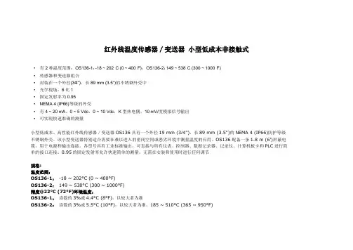
红外线温度传感器/变送器小型低成本非接触式•有2种温度范围:OS136-1:-18 ~ 202°C (0 ~ 400°F),OS136-2:149 ~ 538°C (300 ~ 1000°F)•传感器和变送器组合•封装在一个外径(3⁄4")、长89 mm (3.5")的不锈钢外壳中•光学视场:6比1•固定发射率为0.95•NEMA 4 (IP66)等级的外壳•有4 ~ 20 mA、0 ~ 5 Vdc、0 ~ 10 Vdc,K型热电偶,10 mV/度模拟信号输出•可实现快速准确的测量小型低成本、高性能红外线传感器/变送器OS136具有一个外径19 mm (3⁄4")、长89 mm (3.5")的NEMA 4 (IP66)防护等级不锈钢外壳。
该小型变送器特别适合需要在难以进入的密闭空间或恶劣环境中测量温度的应用。
OS136配备一条1.8 m (6')屏蔽电缆,用于电源和输出连接。
各型号具有工业标准输出,可直接与所有仪表、控制器、数据记录器、记录仪、计算机板卡和PLC进行简单的接口连接。
0.95的固定发射率允许快速简单的测量,无需在安装和使用时进行任何调节规格:温度范围:OS136-1:-18 ~ 202°C (0 ~ 400°F)OS136-2:149 ~ 538°C (300 ~ 1000°F)精度@22°C (72°F)环境温度:OS136-1:读数的3%或4.4°C (8°F),以较大者为准OS136-2:读数的3%或5.5°C (10°F),以较大者为准,185 ~ 510°C (365 ~ 950°F)重复性:读数的1%光学视场:6比1(距离比光点直径)光谱响应: 5 ~ 14微米响应时间:150毫秒,最终值的0 ~ 63%发射率:固定为0.95模拟信号输出:MA:4 ~ 20 mAV1:0 ~ 5 VdcV2:0 ~ 10 VdcK:K型热电偶,补偿MVC:10 mV/°CMVF:10 mV/°F输出负载要求:最低负载(0 ~ 5 Vdc) 1 kΩ最低负载(0 ~ 10 Vdc): 2 kΩ最高负载(4 ~ 20 mA):(电源– 4)/20 mA 最低负载(10 mV/度):10 kΩ最低负载(K型热电偶):100 kΩ工作环境温度:无水冷:0 ~ 70°C (32 ~ 158°F)有水冷(OS136-WC):0 ~ 200°C (32 ~ 392°F) 有风冷(OS136-WC):0 ~ 110°C (32 ~ 230°F) 工作相对湿度:低于95%相对湿度,无冷凝OS136-WC的水流速:0.25 GPM,室温,最低OS136-WC的空气流速:5 CFM(2.4升/秒)预热时间: 1 ~ 2分钟热冲击:25°C的环境温度突然变化时约为30分钟空气净化器的空气流速:1 CFM (0.5升/秒)变送器外壳:316不锈钢,NEMA 4 (IP66)等级工作电源:12 ~ 24 Vdc @ 50 mA外形尺寸:19(外径)x 89 mm(长)(0.75 x 3.5") 重量:181 g (0.40 lb)激光波长(颜色):630 ~ 670 nm(红色)作用距离:最多9.1 m (30')最高激光功率输出:低于1 mW @ 22°C环境温度安全类别:2类EN60825-1/11.2001FDA类别:II类激光产品;符合21 CFR 1040.10激光射束直径:小于5 mm (0.2")射束发散:低于2 mrad工作温度:0 ~ 50°C (32 ~ 122°F)工作相对湿度:低于95%相对湿度,无冷凝电源开关:电池盒上的滑动开关电源指示灯:红色LED工作电源:电池盒,3 Vdc(随附)注意和认证标签:位于激光头瞄准圆周上识别标签:位于激光头瞄准圆周上孔径标签:位于激光头瞄准圆周上外形尺寸:38(厚)x 50.8 mm(长)(1.5 x 2")。

基于单片机的温度检测系统摘要随着时代的进步和发展,单片机技术已经普及到我们生活,工作,科研,各个领域,已经成为一种比较成熟的技术。
单片机在温度检测方面得到广泛应用。
本文将介绍一种基于单片机控制的数字温度计,提出一种基于单片机并采用数字化温度测控系统应用于室温检测的设计方案,该方案是利用温度传感器将室内温度的变化,变换成电压的变化,其值由单片机处理,最后由单片机去控制数字显示器,显示室内的实际温度。
该系统具有温度上、下限报警功能。
本文从硬件和软件两方面详细叙述了基于AT89C51的温度检测系统,该系统以DS18B20为温度检测装置,并附加了温度显示和超温报警功能。
温度采集传感器DS18B20直接以单线连接的方式进行信号传输,采用数字化数据传送方式大大提高了系统的抗干扰性。
因此,数字化单总线器件DS18B20适合于各种环境的现场温度测量。
它在测温精度、转换时间、传输距离、分辨率等方面较以前的温度传感器都有了很大的改进,系统具有结构简单,运行可靠,误差小,且成本低廉等特点。
本文还对AT89C51及DS18B20进行了详细的叙述,并对系统原理进行了仔细分析。
关键词单片机;传感器;温度测量Based on single-chip temperature detection systemAbstractWith the progress and development, single-chip technology has spread to our lives, work; research in various fields has become a relatively mature technology. Single-chip temperature testing is widely used. This article will introduce the single-chip microcomputer-based control of a digital thermometer, and a single-chip digital-based temperature measurement and control system used in the design of room temperature detection program, which is the use of the indoor temperature sensor to temperature change, transform into changes in voltage, and its value from single-chip processing, and finally by the single-chip microcomputer to control the digital display shows actual room temperature. The system has a temperature, the lower limit alarm function.In this paper, both hardware and software described in detail the temperature AT89C51-based detection system to DS18B20 device for temperature detection and temperature display and an additional over-temperature alarm function. Acquisition sensors temperature DS18B20 connect directly to the way one-way signal transmission, the use of digital data transmission system greatly enhanced the anti-interference. Therefore, the number of single-bus device DS18B20 environment suitable for all kinds of temperature measurements at the scene. In the temperature measurement accuracy, conversion time, transmission distance, resolution,etc. than before the temperature sensor has a lot of improvement, the system has a simple structure, reliable operation, the error small, and characteristics of low-cost. In this paper, AT89C51 and DS18B20 also carried out a detailed description of the system conducted a careful analysis of Principle.Keywords Single-chip;Sensor;Temperature measurement不要删除行尾的分节符,此行不会被打印目录摘要 (I)Abstract II第1章绪论 11.1 课题背景 11.2 国外温度测量技术的发展情况 11.3 国内温度测量技术的发展情况 21.4 论文研究内容 2第2章传感器及相关器件介绍42.1 温度传感器的选择42.1.1 DS18B20温度传感器简介 42.1.2 DS18B20的性能特点52.1.3 DS18B20的管脚排列52.1.4 DS18B20的内部结构62.1.5 DS18B20的测温原理82.1.6 DS18B20的时序 92.1.7 DSl8B20使用中的注意事项102.2 单片机概述102.2.1 AT89C51芯片主要性能112.2.2 AT89C51芯片的内部结构框图122.2.3 AT89C51 芯片的引脚说明122.2.4 使用AT89C51编程时需注意事项162.3 显示电路的组成器件172.3.1 LED显示器的介绍172.3.2 74LS164芯片的介绍172.4 本章小结19第3章系统硬件电路设计 213.1 系统硬件电路构成213.1.1 系统整体电路及测温原理21 3.1.2 DS18B20的控制方法233.1.3 显示电路的连接253.2 系统主要技术指标263.3 本章小结26第4章系统软件的设计274.1 主程序设计274.2 测温子程序284.3 显示子程序294.4 本章小结29结论30致谢31参考文献32附录A 33附录B 38附录C 41附录D 42千万不要删除行尾的分节符,此行不会被打印。
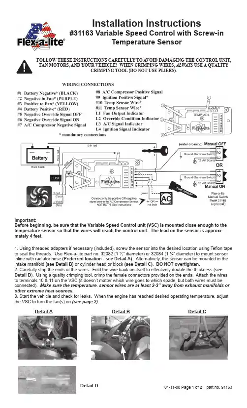
1. Using threaded adapters if necessary (included), screw the sensor into the desired location using Teflon tape to seal the threads. Use Flex-a-lite part no. 32082 (1 ½” diameter) or 32084 (1 ¾” diameter) to mount sensor inline with radiator hose (Preferred location - see Detail A). Alternatively, the sensor can be mounted in the intake manifold (see Detail B) or cylinder head or block (see Detail C). DO NOT overtighten.2. Carefully strip the ends of the wires. Fold the wire back on itself to effectively double the thickness (see Detail D ). Using a quality crimping tool, crimp the female connectors provided on the ends. Attach the wires to terminals 10 & 11 on the VSC (it doesn’t matter which wire goes to which spade, but both wires must be connected). Make sure the temperature. sensor wires are at least 2-3” away from exhaust manifolds or other extreme heat sources.3. Start the vehicle and check for leaks. When the engine has reached desired operating temperature, adjust the VSC to turn the fan(s) on (see page 2). Detail A Detail B Important:Before beginning, be sure that the Variable Speed Control unit (VSC) is mounted close enough to the temperature sensor so that the wires will reach the control unit. The lead on the sensor is approxi-mately 4 feet.Installation Instructions#31163 Variable Speed Control with Screw-in Temperature Sensor01-11-08 Page 1 of 2 part no. 91163FOLLOW THESE INSTRUCTIONS CAREFULLY TO A VOID DAMAGING THE CONTROL UNIT, FAN MOTORS, AND YOUR VEHICLE! WHEN CRIMPING WIRES, ALWAYS USE A QUALITYCRIMPING TOOL (DO NOT USE PLIERS). Detail CDetail DPage 2 of 2 01-11-08 part no. 91163The Flex-a-lite Limited WarrantyFlex-a-lite Consolidated, 7213-45th St. Ct. E. Fife, WA 98424, Telephone No. 253-922-2700, warrants to the original purchasing user, that all Flex-a-lite products to be free of defects in material and workmanship for a period of 365 days (1 year) from date of purchase. Flex-a-lite products failing within 365 days (1 year) from date of purchase may be returned to the factory through the point of purchase, transportation charges prepaid. If, on inspection, cause of failure is determined to be defective material or workmanship and not by misuse, accidental or improper installation, Flex-a-lite will replace the product free of charge, transportation prepaid. Flex-a-lite will not be liable for incidental, progressive or consequential damages. Some states do not allow the exclusion or limitation of incidental or consequential damages, so the above limitation or exclusion may not apply to you. This warranty gives you specific legal rights and you may have other rights, which vary from state to state. The Flex-a-lite warranty is in compliance with the Magnuson-Moss Warranty Act of 1975.1. Turn ignition on. After 6 seconds, LED #L4 should light up. If not, check to make sure that there is 12 Volts at terminal #9 on VSC. The delay is to allow starter to start the vehicle withoutthe fans drawing any power.2. With your engine running, engage the A/C. The fans should come on and cycle with the A/C clutch. LED’s #L1, L3 and L4 should be lit when fans are running. If they do not turn on, verifythat the A/C clutch is engaged and make sure you have a positive signal when the clutch is engaged at terminal #8 (OR negative signal at terminal on #7 if A/C compressor is triggered by a negative signal) on the VSC. Shut off A/C and let engine continue to idle, or drive the vehicle a short distance to bring the engine to operating temperature (monitor the vehicle’s tempera-ture gauge).3. Verify that the operating temperature has been reached by feeling the upper radiator hose. Hot water should be flowing through hose into the radiator. If the fans have not cycled on yet,slowly adjust the screw on the VSC until the fans cycle on. Turning the screw counterclock-wise will keep the engine at a lower temperature, and turning in the opposite direction will keep the engine at a higher temperature. NOTE: THE TOTAL MOVEMENT OF THE ADJUST-MENT SCREW IS ABOUT ¾ OF A TURN. TURNING THE SCREW BEYOND THE LIMITS WILL DAMAGE THE UNIT!4. Once desired temperature is set, let the engine continue to idle and make sure the fans willcycle to maintain desired temperature. When fans are running, LED’s #L1 and L4 should be lit. VERIFY THE DIRECTION OF BLADE ROTATION. IF THE FAN IS MOUNTED TO THE ENGINE SIDE OF THE RADIATOR, THE FAN SHOULD BE PULLING AIR THROUGH THE RADIATOR.Initial Start-up and Adjustment ProcedureThe Variable Speed Control has new features!At the set temperature, the fans will come on at 60%; this reduces the load on your charging system. If the temperature rises, the fan speed will increase. If your set temperature is 195°F, then between 195° and 205° the fan speed will increase from 60% to 100%. So after a 10-degree rise from the set point, the fans will be running at 100%.Turning screw counterclockwise = cooler temp.Turning screw clockwise = warmer temp.。
PRTXB SeriesRTD Process ThermometersM-4998/0818Thermowell required for spring-loaded versionsRange and Resolution User selectable °F, °C or K –58.0°F to 392.0°F –50.0°C to 200.0°C 220.0K to 475.0K 0.1 degree resolutionTypical AccuracyIncludes linearity error and ±1 LSD 11-point linearization ±0.7°C at –50°C ±0.4°C at 0°C ±0.9°C at 100°C ±1.4°C at 200°CDisplay4 readings per second nominal display update rate 4 digit LCD, 0.5" H,5 character 0.25" H alphanumeric BL models: red LED backlightSensorIEC-751 Class B 100 Ω Platinum RTD, 0.00385 alpha curve 1/2" NPT male, 316 stainless steelSpring-loaded probe versions fit standard thermowells Fixed probe pressure rating: 5000 psi max. Fixed probes are welded to hex fittingAuto Shutoff TimeFactory default 5 minutes. User settable to 1, 2, 5, 10, 15, 20, 30 minutes, 1, 2, 4, 8 hours, or manual on/off.OFF warning before auto shutoff to allow reset of timer Batteries, Battery Life, Low Battery Indication B: 2 AA alkaline, approx. 1000 hoursBL: 2 AA alkaline, approx. 150 to 750 hours depending on backlight usage.BL: Button press activates backlighting for 1 minute Low battery symbol on displayControls and FunctionsThree front buttons for power on/off, min/max functions, selection of °F, °C, or K, auto shutoff times, calibration and, configuration optionsUser-defined pass codes for configuration and calibration to prevent unauthorized changesMaximum and Minimum ReadingsUser-configurable maximum and/or minimum temperature indication. Factory default configuration MAX/MIN disabled.Choice of MAX only, MIN only, MAX/MIN, or noneOption to retain or clear MAX/MIN temperatures at shutoff Out-of-RangeALARM1 under range indication on display ALARM2 over range indication on displayCalibrationUser settable pass code required to enter calibration mode Zero and span temperature calibrationNon-interactive zero, span, and linearity, ±10% of range Weight Product: 12 ounces (approximately) Shipping:1 pound (approximately)HousingABS/polycarbonate NEMA 4X case, polycarbonate label, rubber rear gasketConnection, Material, Media Compatibility 1/2" NPT male fitting, 316L stainless steel All wetted parts are 316L stainless steelThermowell required for spring-loaded versions Storage Temperature –40 to 203°F (–40 to 95°C)Operating Range–4 to 185°F (–20 to 85°C) at housingX X X X X 88888indicatione-mail:**************For latest product manuals: Shop online at User’s GuideWARNING: This product can expose you to chemicals including lead, nickel and chromium, which are known to the State of California to cause cancer or birth defects or other reproductive harm. For more information go to DescriptionThe PRTXB series is microprocessor controlled industrial RTD temperature indicator with a digital temperature display in a rugged NEMA 4X housing.The temperature reading is linearized for the digital display. The temperature display may be set up to read °F, °C, or kelvin and the auto shutoff time may be set as needed.The unit is capable of automatically capturing and storing maximum and maximum readings. The min/max functionality can be set up as required, and the readings can be either saved or cleared when the unit shuts off.Installation and PrecautionsRead these instructions before installation. Configuration may be easier before installation.The spring-loaded versions must be used with a thermowell. Use a thermowell appropriate for the process.The non-spring-loaded versions can be used in non-pressurized applications or applications with no flow. Due to the hardness of 316 stainless steel, it is recommended that a thread sealant be used to ensure leak-free operation.Do not exceed maximum allowable housing temperature. Install or remove using wrench on probe hex fitting only. Do not attempt to tighten or loosen by turning the housing.OperationPress and release the power button to power up the unit. The unit tests all LCD segments and displays the RTD temperature on the upper display and the temperature units on the lower display. Readings are updated approximately 4 times per second.The RTD probe has a time constant of approximately 10 seconds, typical of an RTD probe in a stainless sheath. Time constant is characterized as the RTD changing to 63.2% of its new temperature span in one time constant, and 95% of its new temperature span in three time constants.If the unit is configured with an auto shutoff time, a five second warning period is provided prior to auto shutoff, during which the display indicates OFF. The auto shutoff timer is reset whenever any button is pressed and released.To shut off the unit manually at any time, press and hold the power button until the display indicates OFF (up to about 5 seconds total if MAX/MIN is enabled) and then release the button.Out-of-Range IndicationsIf the RTD temperature goes above 392°F or 200°C, ALARM1 will be displayed.If the RTD temperature goes below –58°F or –50°C, ALARM2 will be displayed.If the RTD temperature continues beyond these limits, the display will eventually indicate 1.-.-.-.MAX/MIN Operation (if enabled)The factory default setting has min/max disabled. To turn this feature on, see the section titled User Configuration Mode. The unit may be configure to use max, min, neither, or both.To step the unit through the display modes, press and hold the power button about 1 second until the display indicates MAX or MIN and then release the button. The display mode cycle repeats through the following steps.MAX ModeThe display indicates the stored maximum reading and the lower display alternates between indicating MAX and the temperature units. The thermometer may be left in this mode if desired.User Configuration ModeWith the unit off, press and hold the s button.Then press the power button.Release all buttons when the display indicates CFG.Before the unit enters the configuration mode, the display initially indicates _ _ _ _ with the first underscore blinking, and with CFGPC on the lower display.The unit will automatically revert to normal operation if no buttons are operated for approximately 15 seconds. To cancel and return to normal operation, press and release the power button without entering any pass code characters.Enter the user-modifiable configuration pass code (3510 factory default).Use the s and tbuttons to set the left-most digit to 3.Press and release the power button to index to the next position. The 3 will remain, and the second position will be e the s and t buttons to select 5.Press and release the power button to index to the next position. 3 5 will remain, and the third position will be e the s and t buttons to select 1.Press and release the power button to index to the next position. 3 5 1 will remain, and the fourth position will be e the s and t buttons to select 0.Press and release the power button to proceed with configuration procedures. Note: If an incorrect pass code is entered, the unit will return to the start of the pass code entrysequence.MAX/MIN Capture Configuration The upper display will be blank.Use the sand t buttons to select from the following.MX/MN Both highest and lowest values willbe capturedMX/-- Only highest value will be captured --/MN Only lowest value will be captured --/--Capture feature is disabledPress and release the power button to move on to the next parameter.Auto/Manual MAX/MIN Clearing The upper display will indicate clr.Use the s and t buttons to select from the following.AUTO Maximum and minimum values willautomatically be cleared whenever the unit shuts off.MANMaximum and minimum values will be retained and must be cleared manually as desired.Press and release the power button to save the user configuration and restart the unit.ALARM 1ALARM 2DEG FX X X X X 88888keep onto turn offttRelease buttonsIncrement Move to Increment Move to Press to enter con-t*Select min Press to save and Select auto or Press to save andrestartCalibrationThe PRTXB is factory calibrated and there is generally no need to alter calibration settings. Required calibration equipment includes a temperature reference of at least four times the unit’s accuracy, a dry-block calibrator or a temperature controlled bath.Calibration may be performed in any of the available temperature units, the use of Fahrenheit or Celsius is assumed in this procedure. Select the temperature units for calibration prior to entering the calibration mode.The unit enters and remains in the calibration mode until restarted manually or power is removed. While in the calibration mode, the auto shutoff timer is disabled, and the Min/Max feature is disabled.The unit is calibrated at two points, at ice point and at a temperature above ice point.For general service, the full scale temperature is normally used for the second point. However, if a particular temperature is of critical interest it may be used instead for greatest accuracy at that point.Enter Calibration ModeTo enter the calibration mode, begin withthe unit powered off, and press and hold thet button.Then press the power button.Release all buttons when the displayindicates CAL.Before the unit enters the calibration mode,the display initially indicates _ _ _ _ with thefirst underscore blinking, and with CALPC onthe lower display.Note: The unit will automatically revert tonormal operation if no buttons are operatedfor approximately 15 seconds.To cancel and return to normal operation,press and release the power button withoutentering any pass code characters.Enter the user-modifiable pass code (3510factory default).Use the s and t buttons to set the left-most digit to 3.Press and release the power button to indexto the next position. The 3 will remain, andthe second position will be blinking.Use the s and t buttons to select 5.Press and release the power button to indexto the next position. 3 5 will remain, and thethird position will be blinking.Use the s and t buttons to select 1.Press and release the power button to indexto the next position. 3 5 1 will remain, andthe fourth position will be blinking.Use the s and t buttons to select 0.Press and release the power button toproceed with calibration.Note: If an incorrect pass code is entered, theunit will return to the start of the pass codeentry sequence.Calibration ProcedureUpon successful pass code entry, theupper display will indicate the RTD probe temperature. The lower display will alternateas indicated below.Note: To store the calibration parametersand exit calibration mode at any time, pressand hold the power button until the displayindicates - - - -.Ice-Point CalibrationWhen the applied temperature is belowapproximately 12 °C (or 54 °F), the unit willautomatically select the ice-point calibrationmode.Apply 0.0 °C or 32.0 °F to the RTD.The lower display will alternate between ICEand DEG C or DEG F.Use the s and t buttons to adjust the upperdisplay to indicate 0.0 °C or 32.0 °F.Span CalibrationApply full-scale temperature to the RTD.The lower display segments will alternatebetween CAL and DEG C or DEG F.Use the s and t buttons to adjust the upperdisplay segments to indicate the appliedtemperature value.To store the calibration parameters and exitcalibration mode, press and hold the powerbutton until the display indicates - - - - .Changing the Pass CodesThe factory default pass code of 3510 may be changed ifdesired. Separate pass codes may be used for min/maxconfiguration access and calibration access.Configuration Pass Code AccessWith the unit off, press and hold the sbutton.Then press the power button.Release all buttons when the displayindicates CFG.Calibration Pass Code AccessWith the unit off, press and hold the t buttonto view and/or change the user calibrationpass code.Then press the power button.indicates CAL.View/Change Pass CodeBefore the unit enters the view or changepass code mode, the display initially indicates_ _ _ _ with the first underscore blinking,and with CFG PC or CALPC on the lowerdisplay.Note: The unit will automatically revert tonormal operation if no buttons are operatedfor approximately 15 seconds.To cancel and return to normal operation,press and release the power button withoutentering any pass code characters.Enter Access Code 1220Use thes and t buttons to set the left-most digit to 1.Press and release the power button to indexto the next position. The 1 will remain, andthe second position will be blinking.Use the s andt buttons to select 2.Press and release the power button to indexto the next position. 1 2 will remain, and thethird position will be blinking.Use the s and t buttons to select 2.Press and release the power button to indexto the next position. 1 2 2 will remain, andthe fourth position will be blinking.Use the s andt buttons to select 0.Note: If an incorrect access code wasentered, the unit will return to the start of theaccess code entry sequence.Press and release the power button toproceed.The display will indicate the existing user-defined pass code with CFGPC or CALPC onthe lower display. To exit without changes,press the power button.Operate the s andt button to selectthe first character of the new pass code.Characters 0-9 and A, b, C, d, E, F may beused.When the correct first character is beingdisplayed, press and release the powerbutton to proceed to the next pass codecharacter.Repeat above until the entire pass code iscomplete.To exit the view or change pass code mode,press and hold the power button.Release the button when the displayindicates - - - - to restart the unit.Press to save andrestartIncrement upor downIncrement upor down- or -cfgpci___IncrementMove toIncrementMove tonext #IncrementMove toIncrementMove toPress to enterIncrementMove toIncrementMove toPress to save andrestartPress to enter passcode configurationOMEGA’s policy is to make running changes, not model changes, whenever an improvement is possible. This affordsour customers the latest in technology and engineering.OMEGA is a registered trademark of OMEGA ENGINEERING, INC.© C opyright 2017 OMEGA ENGINEERING, INC. All rights reserved. This document may not be copied, photocopied, reproduced, translated, or reduced to any electronic medium or machine-readable form, in whole or in part, without the prior written consent of OMEGA ENGINEERING, INC.FOR WARRANTY RETURNS, please have thefollowing information available BEFORE contacting OMEGA:1. P urchase Order number under which the productwas PURCHASED,2. M odel and serial number of the product underwarranty, and3. Repair instructions and/or specific problemsrelative to the product.FOR NON-WARRANTY REPAIRS, consult OMEGA for current repair charges. Havethe following information available BEFORE contacting OMEGA:1. Purchase Order number to cover the COST of the repair,2. Model and serial number of the product, and 3. Repair instructions and/or specific problems relative to the product.RETURN REQUESTS/INQUIRIESDirect all warranty and repair requests/inquiries to the OMEGA C ustomer Service Department. BEFORE RETURNING ANY PRODUC T(S) TO OMEGA, PURC HASER MUST OBTAIN AN AUTHORIZED RETURN (AR) NUMBER FROM OMEGA’S C USTOMER SERVIC E DEPARTMENT (IN ORDER TO AVOID PROCESSING DELAYS). The assigned AR number should then be marked on the outside of the return package and on any correspondence.The purchaser is responsible for shipping charges, freight, insurance and proper packaging to prevent breakage in transit.WARRANTY/DISCLAIMEROMEGA ENGINEERING, INC. warrants this unit to be free of defects in materials and workmanship for a period of 13 months from date of purchase. OMEGA’s WARRANTY adds an additional one (1) month grace period to the normal one (1) year product warranty to cover handling and shipping time. This ensures that OMEGA’s customers receive maximum coverage on each product.If the unit malfunctions, it must be returned to the factory for evaluation. OMEGA’s C ustomer Service Department will issue an Authorized Return (AR) number immediately upon phone or written request. Upon examination by OMEGA, if the unit is found to be defective, it will be repaired or replaced at no charge. OMEGA’s WARRANTY does not apply to defects resulting from any action of the purchaser, including but not limited to mishandling, improper interfacing, operation outside of design limits, improper repair, or unauthorized modification. This WARRANTY is VOID if the unit shows evidence of having been tampered with or shows evidence of having been damaged as a result of excessive corrosion; or current, heat, moisture or vibration; improper specification; misapplication; misuse or other operating conditions outside of OMEGA’s control. Components in which wear is not warranted, include but are not limited to contact points, fuses, and triacs.OMEGA is pleased to offer suggestions on the use of its various products. However, OMEGA neither assumes responsibility for any omissions or errors nor assumes liability for any damages that result from the use of its products in accordance with information provided by OMEGA, either verbal or written. OMEGA warrants only that the parts manufactured by the company will be as specified and free of defects. OMEGA MAKES NO OTHER WARRANTIES OR REPRESENTATIONS OF ANY KIND WHATSOEVER, EXPRESSED OR IMPLIED, EXCEPT THAT OF TITLE, AND ALL IMPLIED W ARRANTIES INCLUDING ANY W ARRANTY OF MERCHANTABILITY AND FITNESS FOR A PARTICULAR PURPOSE ARE HEREBY DISCLAIMED. LIMITATION OF LIABILITY: The remedies of purchaser set forth herein are exclusive, and the total liability of OMEGA with respect to this order, whether based on contract, warranty, negligence, indemnification, strict liability or otherwise, shall not exceed the purchase price of the component upon which liability is based. In no event shall OMEGA be liable for consequential, incidental or special damages.CONDITIONS: Equipment sold by OMEGA is not intended to be used, nor shall it be used: (1) as a “Basic Component” under 10 CFR 21 (NRC), used in or with any nuclear installation or activity; or (2) in medical applications or used on humans. Should any Product(s) be used in or with any nuclear installation or activity, medical application, used on humans, or misused in any way, OMEGA assumes no responsibility as set forth in our basic WARRANTY /DISCLAIMER language, and, additionally, purchaser will indemnify OMEGA and hold OMEGA harmless from any liability or damage whatsoever arising out of the use of theProduct(s) in such a manner.。
数字温度计设计毕业设计(二)引言概述数字温度计是一种用于测量温度的电子设备,它通过传感器将温度转换为数字信号,然后显示在数字屏幕上。
本文将针对数字温度计的设计进行详细讨论,包括硬件设计和软件设计两个主要方面。
硬件设计部分将包括传感器选择、信号调理电路设计和数字显示设计;软件设计部分将包括嵌入式程序设计和用户界面设计。
通过本文的详细介绍,读者将能够了解到数字温度计的设计原理、设计流程和关键技术。
正文内容1. 传感器选择1.1 温度传感器类型1.2 温度传感器比较与选择1.3 温度传感器参数测试与校准2. 信号调理电路设计2.1 信号条件2.2 放大和滤波电路设计2.3 ADC(模数转换器)选型和使用3. 数字显示设计3.1 显示芯片选型和使用3.2 显示屏尺寸和分辨率选择3.3 显示内容设计和显示方式选择4. 嵌入式程序设计4.1 控制器选型和使用4.2 温度数据采集与处理4.3 温度数据存储和传输5. 用户界面设计5.1 按键和控制部分设计5.2 显示界面设计与实现5.3 温度单位与切换设计正文详细阐述1. 传感器选择1.1 温度传感器类型在数字温度计的设计中,可以选择多种温度传感器,包括热电偶、热敏电阻和半导体温度传感器等。
本文将比较各种传感器的特点和适用范围,从而选择最合适的传感器。
1.2 温度传感器比较与选择通过比较热电偶、热敏电阻和半导体温度传感器的精度、响应时间和成本等特点,结合设计需求和成本预算,选择最佳的温度传感器。
1.3 温度传感器参数测试与校准为了确保传感器的准确性,需要对其参数进行测试和校准。
本文将介绍传感器参数测试的方法和仪器,以及校准的步骤和标准。
2. 信号调理电路设计2.1 信号条件传感器输出的信号需要进行电平调整和滤波等处理,以便进一步处理和显示。
本文将介绍信号调理的基本原理和设计方法。
2.2 放大和滤波电路设计为了放大和滤波传感器输出的微弱信号,本文将介绍放大和滤波电路的设计原理和实现方法,包括运放、滤波器和滤波器的选型和参数设置。
V = 1 +V V R R 11 + sR C((((Product Folder Order Now Technical Documents Tools &SoftwareSupport &CommunityOPA316-Q1,OPA2316-Q1,OPA4316-Q1ZHCSFY0A –NOVEMBER 2016–REVISED JANUARY 2017OPAx316-Q110MHz 、轨到轨输入/输出、低电压、1.8V CMOS 运算放大器1特性•符合汽车类应用的标准•具有符合AEC-Q100标准的下列结果:–器件温度1级:-40℃至+125℃的环境运行温度范围–器件人体放电模型(HBM)静电放电(ESD)分类等级3A–器件带电器件模型(CDM)ESD 分类等级•单位增益带宽:10MHz •低I Q :每通道400µA•宽电源电压范围:1.8V 至5.5V •低噪声:1kHz 时为11nV/√Hz •低输入偏置电流:±5pA •偏移电压:±0.5mV •单位增益稳定•内部射频干扰(RFI)/电磁干扰(EMI)滤波器•扩展温度范围:–40°C 至+125°C2应用•汽车标准:–高级驾驶员辅助系统(ADAS)–车身电子装置和照明–电流感测–电池管理系统3说明OPAx316-Q1系列单通道和双通道运算放大器是新一代低功耗、通用运算放大器的典型代表。
轨到轨输入和输出摆幅、低静态电流(每通道的典型值为400μA )等特性与10MHz 的较宽带宽和超低噪声(1kHz 时为11nV/√Hz )相结合,因此适用于要求兼具快速特性与良好功率比的电路。
低输入偏置电流支持的运算放大器适用于源阻抗高达兆欧级的应用。
OPAx316-Q1的低输入偏置电流产生的电流噪声极低,该器件因此备受高阻抗传感器接口的青睐。
OPAx316-Q1采用稳健耐用的设计,方便电路设计人员使用。
第三章项目说明采购内容一项目说明1本次采购为交钥匙一、项目说明1.本次推销为交钥匙项目,供应商应依据招标代理机构提供的推销文件、各自状况等停止报价的编制,报价应包括推销范围内的全部内容,含货物〔包括质保期内的备品备件、易损件、公用工具等〕的设计、制造、包装、保险、运输、装卸、装置、调试、验收、培训、售后效劳及技术支持等相关效劳的一切费用。
供应商应充沛思索本项目合同实施时期能够发作的一切费用,并承当由此而带来的风险。
凡供应商在报价中未列明但又为货物所必备的项目或遗漏项目,推销人将一概视为已包括在其报价中,在合同执行中将不予思索。
2.供应商应对本项目的商务条款完全照应,假定有偏向须在报价文件商务标书«商务条款偏离表»中予以说明;假定没有,应注明〝无偏离〞字样。
假定没有填写«商务条款偏离表»,即视为供应商声明其完全照应推销文件的商务条款;但评标委员会有权据此就商务标书中实践不照应局部作出废标的决议。
3.供应商所报货物的技术目的应契合本章技术规范的要求,假定有偏向须在报价文件技术标书«技术条款偏离表»中予以说明;假定没有,应注明〝无偏离〞字样。
假定没有填写«技术条款偏离表»,即视为供应商声明其所报货物的技术目的完全契合技术规范的要求;但评标委员会有权据此就技术标书中实践不照应局部作出废标的决议。
4.售后效劳供应商应提供及时周到的售后效劳,提供全天24小时效劳。
出现缺点,卖方技术人员应在4小时内抵达现场维修,确保24小时内修复。
供应商应在报价文件中提出详细的本地化的售后维修效劳方案。
5.交货/完工期、交货地点、质保期、付款方式详见推销文件第五章«合同特殊条款»。
二、推销内容注:1、全自动板式换热机组招标范围包括机组控制柜至机组外部动力电缆及信号电缆衔接。
2、循环水泵选用变频器功率应比水泵配用电机功率高一个规格,变频器应设在防护柜内。