EMC test report
- 格式:pdf
- 大小:844.00 KB
- 文档页数:24
无极灯EMC测试报告EMC TEST REPORTforXiamen RuiMeng Environmental Protection Technology Co., Ltd.Electromagnetic Induction LightingModel No: List of the model No. refer the appendix IReport No. : ATE20110727 Date of Test : May 2-3, 2011 Date of Report : May 4, 2011Prepared for : Xiamen RuiMeng Environmental Protection TechnologyCo., Ltd.Address : Rm 702, No.16, Tong’An Industrial Park, Xiamen East Coastal Area, P.R.CPrepared By : Accurate Technology Co., Ltd.Address : F1, Bldg. A&D, Changyuan New Material Port, Keyuan Rd. Science & Industry Park, Nanshan District, Shenzhen 518057, P.R. China Tel: +86-755-26503290 Fax: +86-755-26503396TABLE OF CONTENTSDescription PageTest Report Declaration1.TEST RESULTS SUMMARY (6)2.GENERAL INFORMATION (7)2.1.Description of Device (EUT) (7)2.2.Accessory and Auxiliary Equipment (7)2.3.Description of Test Facility (8)2.4.Measurement Uncertainty (8)3.MEASURING DEVICES AND TEST EQUIPMENT (9)3.1.For Conducted Emission Test (9)3.2.For Magnetic Measurement (9)3.3.For Radiated Emission Measurement (10)3.4.For Harmonic & Flicker Test (10)3.5.For Electrostatic Discharge Immunity Test (10)3.6.For RF Strength Susceptibility Test (11)3.7.For Electrical Fast Transient /Burst Immunity Test (11) 3.8.For Surge Immunity Test (11)3.9.For Injected Current Susceptibility Test (11)3.10.For Magnetic Field Immunity Test (12)3.11.For Voltage Dips and Interruptions Test (12)4.POWER LINE CONDUCTED MEASUREMENT (13)4.1.Block Diagram of Test Setup (13)4.2.Measurement Standard and Limits (13)4.3.Power Line Conducted Emission Limits (13)4.4.EUT Configuration on Measurement (13)4.5.Operating Condition of EUT (14)4.6.Test Procedure (14)4.7.Measurement Results (15)5.MAGNETIC FIELD EMISSION MEASUREMENT (17)5.1.Block Diagram of Test Setup (17)5.2.Measurement Standard (17)5.3.Magnetic Field Emission Limits (17)5.4.EUT Configuration on Measurement (17)5.5.Operating Condition of EUT (17)5.6.Test Procedure (18)5.7.Test Results (19)6.RADIATED EMISSION MEASUREMENT (23)6.1.Block Diagram of Test (23)6.2.Measuring Standard (23)6.3.Radiated Emission Limits (24)6.4.EUT Configuration on Test (24)6.5.Operating Condition of EUT (24)6.6.Test Procedure (24)6.7.Measuring Results (25)7.HARMONIC CURRENT MEASUREMENT (27)7.1.Block Diagram of Test Setup (27)7.2.Measuring Standard (27)7.3.Operating Condition of EUT (27)7.4.Test Results (27)8.VOLTAGE FLUCTUATIONS & FLICKER MEASUREMENT (31) 8.1.Block Diagram of Test Setup (31)8.2.Measuring Standard (31)8.3.Operating Condition of EUT (31)8.4.Test Results (31)9.ELECTROSTATIC DISCHARGE TEST (33)9.1.Block Diagram of Test Setup (33)9.2.Test Standard (33)9.3.Severity Levels and Performance Criterion (33)9.4.EUT Configuration (34)9.5.Operating Condition of EUT (34)9.6.Test Procedure (34)9.7.Test Results (34)10.RF FIELD STRENGTH SUSCEPTIBILITY TEST (36)10.1.Block Diagram of Test Setup (36)10.2.Test Standard (36)10.3.Severity Levels and Performance Criterion (37)10.4.EUT Configuration (37)10.5.Operating Condition of EUT (37)10.6.Test Procedure (37)10.7.Test Results (37)11.ELECTRICAL FAST TRANSIENT/BURST TEST (39) 11.1.Block Diagram of Test Setup (39)11.2.Test Standard (39)11.3.Severity Levels and Performance Criterion (39) 11.4.EUT Configuration (39)11.5.Operating Condition of EUT (40)11.6.Test Procedure (40)11.7.Test Result (40)12.SURGE IMMUNITY TEST (42)12.1.Block Diagram of Test Setup (42)12.2.Test Standard (42)12.3.Severity Levels and Performance Criterion (42) 12.4.EUT Configuration (43)12.5.Operating Condition of EUT (43)12.6.Test Procedure (43)12.7.Test Result (43)13.INJECTED CURRENTS SUSCEPTIBILITY TEST (45) 13.1.Block Diagram of Test Setup (45)13.2.Test Standard (45)13.3.Severity Levels and Performance Criterion (45) 13.4.EUT Configuration (46)13.5.Operating Condition of EUT (46)13.6.Test Procedure (46)13.7.Test Results (46)14.MAGNETIC FIELD IMMUNITY TEST (48)14.1.Block Diagram of Test Setup (48)14.2.Test Standard (48)14.3.Severity Levels and Performance Criterion (48) 14.4.EUT Configuration (49)14.5.Operating Condition of EUT (49)14.6.Test Procedure (49)14.7.Test Results (49)15.VOLTAGE DIPS AND INTERRUPTIONS TEST (51)15.1.Block Diagram of Test Setup (51)15.2.Test Standard (51)15.3.Severity Levels and Performance Criterion (51)15.4.EUT Configuration (52)15.5.Operating Condition of EUT (52)15.6.Test Procedure (52)15.7.Test Result (52)16.PHOTOGRAPH (54)16.1.Photo of Conducted Emission Measurement (54)16.2.Photo of Radiated Measurement (54)16.3.Photo of Electrostatic Discharge Test (55)16.4.Photo of RF Field Strength Susceptibility Test (56)16.5.Photo of Electrical Fast Transient /Burst Test (56)16.6.Photo of Surge and Voltage Dips and Interruption Immunity Test (57)16.7.Photo of Injected Current Susceptibility Test (57)16.8.Photo of Magnetic Field Immunity Test (58)16.9.Photo of EUT (58)TEST REPORT DECLARATIONApplicant : Xiamen RuiMeng Environmental Protection Technology Co.,Ltd.Manufacturer : Xiamen RuiMeng Environmental Protection Technology Co.,Ltd.Product : Electromagnetic Induction LightingModel No. : List of the model No. refer the appendix IMeasurement Procedure Used:EN 55015: 2006 + A1: 2007 + A2: 2009EN 61000-3-2:2006 + A1:2009 +A2: 2009EN 61000-3-3: 2008EN 61547: 2009 (IEC61000-4-2: 2008IEC61000-4-3: 2010IEC61000-4-4: 2004IEC61000-4-5: 2005IEC61000-4-6: 2008IEC61000-4-8: 2009IEC61000-4-11: 2004)The device described above is tested by Accurate Technology Co., Ltd. To determinethe maximum emission levels emanating from the device and the severe levels of thedevice can endure and its performance criterion. The measurement results arecontained in this test report and Accurate Technology Co., Ltd. is assumed fullresponsibility for the accuracy and completeness of these measurements. Also, thisreport shows that the EUT to be technically compliant with the EN 55015, EN61000-3-2, EN 61000-3-3 and EN 61547 requirements.This report applies to above tested sample only and shall not be reproduced in partwithout written approval of Accurate Technology Co., Ltd.Date of Test : May 2-3, 2011Prepared by :(Engineer)Approved & Authorized Signer :(Manager)1. TEST RESULTS SUMMARYTest Items Test Standard Test ResultsPower Line Conducted EmissionEN 55015: 2006 +A1: 2007 + A2: 2009PassMagnetic Field EmissionEN 55015: 2006 +A1: 2007 + A2: 2009PassRadiated EmissionEN 55015: 2006 +A1: 2007 + A2: 2009PassHarmonic Current EN 61000-3-2:2006 +A1:2009 +A2: 2009PassVoltage Fluctuation and Flicker EN 61000-3-3: 2008 Pass Electrostatic Discharge Immunity EN 61547: 2009 (IEC61000-4-2:2008)PassRadiated Electromagnetic Fields Immunity EN 61547: 2009 (IEC61000-4-3:2010)PassElectrical Fast Transients/Bursts Immunity EN 61547: 2009 (IEC61000-4-4:2004)PassSurge Immunity EN 61547: 2009(IEC61000-4-5:2005)PassInjected Current Susceptibility Test EN 61547: 2009(IEC61000-4-6:2008)PassMagnetic Field Immunity EN 61547: 2009(IEC61000-4-8:2009)PassVoltage dips and interruptions Immunity EN 61547: 2009 (IEC61000-4-11:2004)Pass2. GENERAL INFORMATION2.1.Description of Device (EUT)Product : Electromagnetic Induction LightingModel Number : List of the model No. refer the appendix I (Note: These samples are identical, except the power isdifference. Therefore onlymodel RM-EIL-HB-004 80W-200W is tested for EMC tests.) Rating : AC 230V/50HzApplicant : Xiamen RuiMeng Environmental Protection Technology Co.,Ltd.Address : Rm 702, No.16, Tong’An Industrial Park, Xiamen EastCoastal Area, P.R.CManufacturer : Xiamen RuiMeng Environmental Protection Technology Co.,Ltd.Address : Rm 702, No.16, Tong’An Industrial Park, Xiamen EastCoastal Area, P.R.CDate of sample: April 29, 2011receiverDate of Test : May 2-3, 20112.2.Accessory and Auxiliary Equipmentn.a.2.3.Description of Test FacilityEMC Lab :Accredited by TUV Rheinland ShenzhenListed by FCCThe Registration Number is 253065Listed by FCCThe Registration Number is 752051Listed by Industry CanadaThe Registration Number is 5077A-1Listed by Industry CanadaThe Registration Number is 5077A-2Accredited by China National Accreditation Committeefor LaboratoriesThe Certificate Registration Number is L3193Name of Firm :ACCURATE TECHNOLOGY CO. LTDSite Location :F1, Bldg. A, Changyuan New Material Port, KeyuanRd. Science & Industry Park, Nanshan, Shenzhen,Guangdong P.R. ChinaSubcontracted Items::Magnetic Measurement TestRF Strength Susceptibility TestSubcontractor :Shenzhen Academy Of Metrology And QualityInspectionSite Location :Bldg. Of Shenzhen Academy Of Metrology And Quality Inspection, Longzhu Road, Nanshan,Shenzhen, Guangdong P. R. China2.4.Measurement UncertaintyConducted emission expanded uncertainty : U=2.23dB, k=2 Power disturbance expanded uncertainty : U=2.92dB, k=2Radiated emission expanded uncertainty: U= 3.08dB, k= 2 (9kHz-30MHz)Radiated emission expanded uncertainty: U= 4.42dB, k= 2 (30MHz-1000MHz)Radiated emission expanded uncertainty: U= 4.06dB, k= 2 (Above 1GHz)3. MEASURING DEVICES AND TEST EQUIPMENT3.1.For Conducted Emission TestItem Equipment Manufacturer Model No.Serial No. Last Cal. Cal. Interval1. Test Receiver Rohde & Schwarz ESCS30 100307 Jan. 15, 20111 Year2. Test Receiver Rohde & Schwarz ESPI3 100396/003 Jan. 15, 20111 Year3. Test Receiver Rohde & Schwarz ESPI3 101526/003 Jan. 15, 20111 Year4. L.I.S.N. Schwarzbeck NSLK81268126431 Jan. 15, 20111 Year5. L.I.S.N. Rohde & Schwarz ESH3-Z5 100305 Jan. 15, 20111 Year6. L.I.S.N. Rohde & Schwarz ESH3-Z5 100310 Jan. 15, 20111 Year7. L.I.S.N. Rohde & Schwarz ESH3-Z6 100132 Jan. 15, 20111 Year8. Pulse Limiter Rohde & Schwarz ESH3-Z2 100305 Jan. 15, 20111 Year9. Pulse Limiter Rohde & Schwarz ESH3-Z2 100312 Jan. 15, 20111 Year10. Pulse Limiter Rohde & Schwarz ESH3-Z2 100815 Jan. 15, 20111 Year11. 50? CoaxialSwitchAnritsu Corp MP59B 6200283936Jan. 15, 20111 Year12. 50? CoaxialSwitchAnritsu Corp MP59B 6200283933Jan. 15, 20111 Year13. 50? CoaxialSwitchAnritsu Corp MP59B 6200506474Jan. 15, 20111 Year14. RF CoaxialCableSUHNER N-2m No.2 Jan. 15, 20111 Year15. RF CoaxialCableSUHNER N-2m No.3 Jan. 15, 20111 Year16. RF CoaxialCableSUHNER N-2m No.13 Jan. 15, 20111 Year 3.2.For Magnetic MeasurementItem Equipment Manufacturer Model No. Serial No.NO. Last Cal. Cal.Interval1. EMI Test Receiver Rohde &Schwarz ESCS30 100003 SB3319Jan 23, 2011 1 Year2. Triple LoopAntennaSchwarzbeck HXYZ91709124 9124 Jan 23, 2011 1 Year3.3. F or Radiated Emission MeasurementItem EquipmentManufacturerModel No.Serial No.Last Cal.Cal.Interval 1. Spectrum Analyzer ANRITSU MS2651B 6200238856 Jan. 15, 2011 1 Year 2. Spectrum Analyzer Agilent E7405A MY45115511 Jan. 15, 2011 1 Year 3. Test Receiver Rohde&Schwarz ESCS30 100307 Jan. 15, 2011 1 Year 4. Test Receiver Rohde& Schwarz ESPI3 100396/003 Jan. 15, 2011 1 Year 5. Test Receiver Rohde& Schwarz ESPI3 101526/003 Jan. 15, 2011 1 Year 6. Bilog Antenna Schwarzbeck VULB9163 9163-194 Jan. 15, 2011 1 Year 7. Bilog Antenna Schwarzbeck VULB9163 9163-323 Jan. 15, 2011 1 Year 8. Loop Antenna Schwarzbeck FMZB1516 1516131 Jan. 15, 2011 1 Year 9. Horn Antenna Schwarzbeck BBHA9120D 9120D-655 Jan. 15, 2011 1 Year 10. Horn Antenna Schwarzbeck BBHA9170 9170-359 Jan. 15, 2011 1 Year 11. 50 Coaxial Switch Anritsu Corp MP59B 6200237248 Jan. 15, 2011 1 Year 12. 50 Coaxial Switch Anritsu Corp MP59B 6200506474 Jan. 15, 2011 1 Year 13. RF Coaxial Cable Schwarzbeck N-5m No.1 Jan. 15, 2011 1 Year 14. RF Coaxial Cable Schwarzbeck N-1m No.6 Jan. 15, 2011 1 Year 15. RF Coaxial Cable Schwarzbeck N-1m No.7 Jan. 15, 2011 1 Year 16. RF Coaxial Cable SUHNER N-3m No.8 Jan. 15, 2011 1 Year 17. RF Coaxial Cable RESENBERGER N-3.5m No.9 Jan. 15, 2011 1 Year 18. RF Coaxial Cable SUHNER N-6m No.10 Jan. 15, 2011 1 Year 19. RF Coaxial Cable RESENBERGER N-12m No.11 Jan. 15, 2011 1 Year 20. RF Coaxial Cable RESENBERGER N-0.5m No.12 Jan. 15, 2011 1 Year 21. Pre-Amplifier Agilent 8447D 294A10619 Jan. 15, 2011 1 Year 22. Pre-Amplifier Rohde&Schwarz CBLU1183540-013791 Jan. 15, 20111 Year3.4.For Harmonic & Flicker Test3.5.For Electrostatic Discharge Immunity TestItem Equipment Manufacturer Model No. Serial No. Last Cal. Cal. Interval 1. ESD TesterHAEFELY PESD1610 H4001552Jan. 15, 20111 YearItem Equipment Manufacturer Model No. Serial No. Last Cal.Cal. Interval1. AC Power Source California Instruments5001iX-40055689 Jan. 15, 20111Year 2. Test analyzer California InstrumentsPACS-1 72254 Jan. 15, 20111Year 3. PC Lenovo L4000 SA03697426 N/AN/A3.6.For RF Strength Susceptibility TestItem Equipment ManufacturerModel No.Serial No. Last Cal. Cal. Interval 1. Signal Generator Rohde&Schwarz SMT03 100059 Jan. 23, 2011 1 Year 2. Voltage Probe Rohde&Schwarz URV5-Z2 100013 Jan. 23, 2011 1 Year 3. Power Amplifier AR 150W1000 300999 Jan. 23, 2011 1 Year 4. Power Amplifier AR 25S1G4AM1305993 Mar. 9, 2010 2 Year 5. Bilog AntennaChase CBL6111C 2576 Jan. 23, 2011 1 Year 6. Anechoic chamberAlbatross Projects MCDC----Mar. 20, 20102 Year3.7.For Electrical Fast Transient /Burst Immunity TestItem Equipment Manufacturer Model No. Serial st Cal.Cal. Interval1. ULTRA COMPACT SIMULATOR EM TESTUCS 500 N5V0928104968Jan. 15, 20111Year2. CAPACITIVE CLAMPEM TESTHFK 0509-34 Jan. 15, 20111Year 3. Transformer EM TESTV4780S20109-44Jan. 15, 20111Year3.8.For Surge Immunity TestItem Equipment ManufacturerModel No. Serial st Cal. Cal. Interval1. ULTRA COMPACT SIMULATOR EM TESTUCS 500 N5 V0928104968Jan. 15, 20111Year 2. Transformer EM TESTV4780S2 0109-44 Jan. 15, 20111Year3.9.For Injected Current Susceptibility TestItem Equipment Manufacturer Model No. Serial No. Last Cal. Cal. Interval 1. Conducted Immunity Test System FRANKONIA CIT-10 126B1121 Jan. 15, 2011 1Year2. CDN FRANKONIA CDN-M2/3 A3027020 Jan. 15, 20111Year3. EM Injection Clamp FCC F-203I-23mm 091824 Jan. 15, 2011 1Year4. Calibration Fixture FCC F-203I-23mm-CF091822 N.A. N.A.5. 6dB Attenuator Weinschel WA59-6-33 A329 Jan. 15, 20111Year6. 150/50 ohms AdaptorFrankonia N/A 025 N.A. N.A.3.10.For Magnetic Field Immunity TestItem Equipment Manufacturer Model No.Serial st Cal. Cal. Interval 1. Magnetic Field Tester HAEFELY MAG100 150577 Jan. 15, 2011 1 Year2. AC Transformer HOKUN TDGC2J-5N/A N/A N/A3.11.For Voltage Dips and Interruptions TestItem Equipment Manufacturer Model No. Serial st Cal. Cal. Interval1. ULTRA COMPACT SIMULATOR EM TESTUCS 500 N5 V0928104968Jan. 15, 20111Year 2. Transformer EM TESTV4780S2 0109-44 Jan. 15, 20111Year4. POWER LINE CONDUCTED MEASUREMENT4.1.Block Diagram of Test Setup(EUT: Electromagnetic Induction Lighting )4.2. M easurement Standard and LimitsEN 55015: 2006 + A1: 2007 + A2: 20094.3. P ower Line Conducted Emission LimitsAt mains terminals dB( V)FrequencyQuasi-peak Level Average Level9kHz - 50KHz 110-- 50kHz - 150KHz 90 - 80* -- 150kHz - 0.5MHz 66 - 56* 56 - 46* 0.5MHz - 5.0MHz 56 46 5.0MHz - 30.0MHz 60 50 1. At thetransition frequency the lower limit applies. 2. * Decreasing linearly with logarithm of the frequency.4.4. E UT Configuration on MeasurementThe following equipments are installed on Conducted Emission Measurementto meet EN55015 requirements and operating in a manner which tends to maximize its emission characteristics in a normal application. 4.4.1.Electromagnetic Induction Lighting (EUT) Model No.:RM-EIL-HB-004 80W-200W Serial No. :N/AManufacturer:Xiamen RuiMeng Environmental Protection Technology Co., Ltd.4.5.Operating Condition of EUT4.5.1.Setup the EUT as shown in Section 4.1.4.5.2.Turn on the power of all equipments.4.5.3.Let the EUT work in test mode (On) and measure it.4.6. T est ProcedureThe EUT is put on the table which is 0.8 meter high above the ground and connected to the AC mains through a Line Impedance Stabilization Network (L.I.S.N.). This provided a 50ohm coupling impedance for the tested equipments. Both sides of AC line are checked to find out the maximum conducted emission according to the EN 55015 regulations during conducted emission measurement. And the voltage probe had been used for the load terminals measurement according to the EN 55015 standard.The bandwidth of the test receiver (R&S ESCS30) is set at 200Hz in 9k~150kHz range and 9kHz in 150k~30MHz range.The frequency range from 9 kHz to 30MHz is checked.4.7.Measurement ResultsPASS.The frequency range 9 kHz to 30MHz is investigated.Test mode: OnEmissions attenuated more than 20 dB below the permissible value are not reported.The spectral diagrams are shown in the following pages.Ambient temperature: 25oC Relative humidity: 50% TestMode: OnTest Specification: LineAmbient temperature: 25oC Relative humidity: 50% Test Mode: OnTest Specification: Neutral5. MAGNETIC FIELD EMISSION MEASUREMENT5.1.Block Diagram of Test Setup(EUT: Electromagnetic Induction Lighting )5.2.Measurement StandardEN 55015: 2006 + A1: 2007 + A2: 20095.3.Magnetic Field Emission LimitsLimits for loop diameter dB( A) Frequency2m9kHz - 70kHz 8870kHz - 150kHz 88 -58*150kHz - 3.0MHz 58 - 22*3.0MHz - 30MHz 221. At the transition frequency the lower limit applies.2. * Decreasing linearly with logarithm of the frequency.5.4.EUT Configuration on MeasurementThe configuration of the EUT is same as Section 4.4.5.5.Operating Condition of EUT5.5.1.Setup the EUT as shown in Section 5.1.5.5.2.Turn on the power of all equipments.5.5.3.Let the EUT work in test mode (On) and measure it.5.6.Test ProcedureThe EUT is placed on a wood table in the center of a loop antenna. The induced current in the loop antenna is measured by means of a current probe and the test receiver. Three field components are checked by means of a coaxial switch.The frequency range from 9 kHz to 30MHz is investigated. The receiver is measured with the quasi-peak detector. For frequency band 9 kHz to 150 kHz, the bandwidth of the field strength meter (R&S test receiver ESCS30) is set at 200Hz. For frequency band 150 kHz to 30MHz, the bandwidth is set at 9 kHz.5.7.Test ResultsPASS.The frequency range from 9 kHz to 30MHz is investigated.Emissions attenuated more than 20 dB below the permissible value are not reported.The spectral diagrams are shown in the following pages.。
电磁兼容(EMC)综述报告20134528005 杨洋电子与通信工程一.引言电子电路在通信、计算机、自动化和其他领域被广泛使用,各种各样的电路必须在互相靠近的情况下工作,很多时候这些电路彼此间会产生不利的影响。
对电路设计人员来说,电磁干扰(EMI)已成为一个主要问题,未来,这个问题肯能会变得更为重要。
大量的普遍使用电子设备是导致这一趋势的一个原因。
此外,集成电路的使用和大规模的集成减小了电子设备的尺寸。
电子电路越来越小,越来越复杂,使越来越多的电路挤进较小的空间,增加了干扰的概率。
此外,多年来时钟频率急剧增加,许多情况下超过了1000MHz。
现在家里使用的个人电脑,时钟速度超过1GHz已经很普遍。
当前,设备设计者需要做的不仅仅是让他们的系统在实验室的理想条件下能运行。
除了这些明显的任务,设计的产品必须工作在其他设备附近的“现实世界”中,并要遵守政府的电磁兼容性(EMC)法规。
这就意味着设备不应受外部电磁源的影响,而且自身也不是一个污染环境的电磁噪声源。
电磁兼容性应该是一个主要的设计目标。
二.正文1)基本概念电子设备受电磁骚扰的影响而出现故障或性能降级,就称为设备对电磁骚扰敏感。
如何在设备与电磁环境之间寻求一种协调的关系和共存的条件就是电磁兼容技术,简称EMC(Electromagnetic Compatibility)。
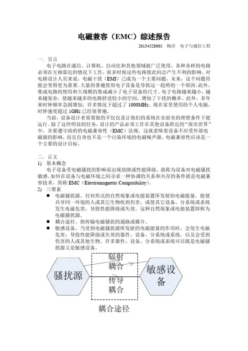
2)三要素●电磁骚扰源。
任何形式的自然现象或电能装置所发射的电磁能量,能使共享同一环境的人或其它生物收到伤害,或使其它设备、分系统或系统发生电磁危害,导致性能降级或失效,这种自然现象或电能装置即称为电磁骚扰源。
●耦合途径。
指传输电磁骚扰的通路或媒介。
●敏感设备。
当受到电磁骚扰源所发射的电磁能量的作用时,会发生电磁危害,导致性能降级或失效的器件、设备、分系统或系统,以及会受到伤害的人或其他生物。
许多器件、设备、分系统或系统可以既是电磁骚扰源又是敏感设备。
骚扰源敏感设备传导耦合辐射耦合耦合途径3)传导耦合与辐射耦合●传导耦合传导耦合是骚扰源与敏感设备之间的主要耦合途径之一。
随着电气电子技术的发展,家用电器产品日益普及和电子化,广播电视、邮电通讯和计算机网络的日益发达,电磁环境日益复杂和恶化,使得电气电子产品的电磁兼容性(EMC电磁干扰EMI 与电磁抗EMS)问题也受到各国政府和生产企业的日益重视。
欧共体政府规定,从1996年1月1起,所有电气电子产品必须通过EMC认证,加贴CE认证标志后才能在欧共体市场上销售。
此举在世界上引起广泛影响,各国政府纷纷采取措施,对电气电子产品的RMC性能实行强制性管理。
根据欧盟的电磁兼容(EMC)指令2004/108/EC,所有在欧盟市场销售的电子电气产品必须在其对其他产品的干扰性及对外来影响的抗干扰性方面严格符合欧盟法律要求。
检验记录产品名称NAME OF SAMPLE商标型号TRADE MARK & TYPE制造厂商MANUFACTURER委托单位CLIENT检验类别TEST SORT检验项目TEST ITEM 静电放电抗扰度、电快速瞬变脉冲群抗扰度、浪涌(冲击)抗扰度检验记录第3 页共页检验负责人:审核:批准:职务:年月日年月日年月日检验项目:浪涌(冲击)抗扰度试验依据标准:IEC 61000-4-5:2005 、企业要求产品名称:商标型号:样品编号:1#试验条件:温度:23 ℃,湿度:52 %RH,正常大气压。
电磁条件保证受试设备正常工作,并不影响试验结果。
EUT状态:试验前工作正常,试验中受试设备刷卡及RS485命令开锁正常,使受试设备处于正常工作状态。
试验等级:在受试设备的DC电源和信号线端口:正-负:电压峰值2kV,开路电压波形1.2/50µs(短路电流波形8/20µs),2Ω内阻正(或负)-地:电压峰值2kV,开路电压波形1.2/50µs(短路电流波形8/20µs),12Ω内阻信号线对线:电压峰值2kV,开路电压波形1.2/50µs(短路电流波形8/20µs),15Ω内阻信号线对地:电压峰值2kV,开路电压波形1.2/50µs(短路电流波形8/20µs),15Ω内阻要求符合性能判据B。
EMC基本测试报告格式及说明随着电气电子技术的发展,家用电器产品日益普及和电子化,广播电视、邮电通讯和计算机网络的日益发达,电磁环境日益复杂和恶化,使得电气电子产品的电磁兼容性(EMC电磁干扰EMI与电磁抗EMS)问题也受到各国政府和生产企业的日益重视。
欧共体政府规定,从1996年1月1起,所有电气电子产品必须通过EMC认证,加贴CE认证标志后才能在欧共体市场上销售。
此举在世界上引起广泛影响,各国政府纷纷采取措施,对电气电子产品的RMC性能实行强制性管理。
根据欧盟的电磁兼容(EMC)指令2004/108/EC,所有在欧盟市场销售的电子电气产品必须在其对其他产品的干扰性及对外来影响的抗干扰性方面严格符合欧盟法律要求。
产品名称NAME OF SAMPLE商标型号 TRADE MARK & TYPE制造厂商MANUFACTURER委托单位CLIENT检验类别TEST SORT检验项目静电放电抗扰度、电快速瞬变脉冲群抗扰度、TEST ITEM浪涌(冲击)抗扰度报告编号: 第页共页检验记录第 3 页共页样品名称商标 /制造厂商型号规格委托单位取样方式委托人送样/ 抽样单位抽样母数 1台/ 样品数量抽样地点 1台送检生产日期 -- 抽样日期 / 2008年11月14日日期检验日期 2008年11月14日--2008年12月4日检验环境 15,35? 45,75%RH 样品说明:#检测样品1台,检测编号:1,检测前后样品外观完好,功能正常。
测试时供电电压:DC 12V检验项目:静电放电抗扰度、浪涌(冲击)抗扰度、电快速瞬变脉冲群抗扰度检测依据: IEC 61000-4-5:2005、IEC 61000-4-2:2001、IEC 61000-4-4-2004、企业要求检验概况:依据标准和企业要求对1台样品分别进行了静电放电抗扰度、浪涌(冲击)抗扰度、电快速瞬变脉冲群抗扰度共3项的检测,测试结果均符合企业要求。
EMC测试报告EMC TEST REPORTReport No: TS12060041-EME Model No: RPI-H3, RPI-H2.5 Issued Date: Jan. 30, 2013Applicant: Address: DELTA ELECTRONICS INC.39 Sec. 2, Huandong Road, Shanhua Dist., Tainan city 74144, TaiwanTest Methods/ Standards: EN 301 489-17 V2.1.1/EN 301 489-1 V1.9.2EN 61000-6-3: 2007+A1: 2011 /EN 61000-6-1: 2007EN 61000-6-4: 2007+A1: 2011/EN 61000-6-2: 2005EN 61000-3-2: 2006+A1: 2009 +A2: 2009EN 61000-3-3: 2008IEC 61000-4-2: 2008/ EN 61000-4-2: 2009ICE 61000-4-3: 2010/ EN 61000-4-3:2006+A1:2008+A2:2010 ICE 61000-4-4 :2012/EN 61000-4-4: 2012IEC 61000-4-5: 2005/ EN 61000-4-5: 2006IEC 61000-4-6: 2008/ EN 61000-4-6: 2009IEC 61000-4-8: 2009/ EN 61000-4-8: 2010IEC 61000-4-11 :2004/EN 61000-4-11: 2004IEC 61000-4-16: 2011IEC 61000-4-18: 2011IEC 61000-4-29: 2000Test By: Intertek Testing Services Taiwan Ltd.,Hsinchu LaboratoryNo. 11, Lane 275, Ko-Nan 1 Street, Chia-Tung Li,Shiang-Shan District, Hsinchu City, TaiwanIt may be duplicated completely for legal use with the allowance of the applicant. It shall not be reproduced except in full, without the written approval of Intertek Laboratory. The test result(s) in this report only applies to the tested sample(s). The test report was prepared by: Sign on FileCandy Liu / AssistantThese measurements were taken by:Sign on FileAnson Lee / EngineerName Arthur TsaiTitle Senior EngineerTable of Contents1. General Information (6)1.1 Identification of the EUT (6)1.2 Additional information about the EUT (7)2. Test Summary (8)2.1 Test requirements (8)3. Test Specifications (11)3.1 Standards (11)3.2 Test Facility accreditation (12)3.3 Classification of ITE (12)3.4 External port (13)3.5 Performance verification (13)3.6 Mode of operation during the test (13)3.7 Peripheral equipment (14)4. Conducted Emission Test (15)4.1 Test arrangement (15)4.2 Photographs of the test arrangement (15)4.3 Test Procedures (15)4.4 Test Equipment (16)4.5 Conducted Emission Limit for AC mains port (16) 4.6 Uncertainty of Conducted Emission (16)4.7 Test Result: Pass (17)5. Radiated Emission Test (19)5.1 Test arrangement (19)5.2 Photographs of the test arrangement (19)5.3 Test Procedures (19)5.4 Test Equipment (20)5.5 Radiated Emission Limit (20)5.2.1 Test Procedure from 1 GHz to 6 GHz (23)5.2.2 Test Equipment (24)5.2.3 Radiated Emission Limit (24)5.2.4 Uncertainty of Radiated Emission (24)5.2.5 Radiated Emission Test Data from 1 GHz to 6 GHz (25)6. Harmonic Test (26)6.1 Test arrangement (26)6.2 Test Procedure & classification (26)6.3 Classification (26)6.4 Test Equipment (27)6.5 Uncertainty of Harmonic (27)6.6 Test Result (28)7. V oltage Fluctuations-Flicker Test (29)7.1 Test arrangement (29)7.2 Test Procedure (29)7.3 Test Equipment (30)7.4 Uncertainty of Flicker (30)7.5 Test result (30)8. Electrostatic Discharge Immunity Test (31)8.1 Test arrangement (31)8.2 Photographs of the test arrangement (31)8.3 Test Procedure (31)8.4 Test Specification (32)8.5 Test Equipment (33)8.6 Requirement (33)8.7 Test Result: Pass (34)9. Radiated Susceptibility Immunity Test (38)9.1 test arrangement (38)9.2 Photographs of the test arrangement (38)9.3 Test Procedure (38)9.7 Generation of the Electromagnetic Field (40)9.8 Test Results: Pass (41)10. Electrical Fast Transient/Burst Immunity Test (42)10.1 Test arrangement (for Main power) (42)10.2 Test arrangement (for DC port) (42)10.3 Test arrangement (for RS-485&RJ45port) (42)10.2 Photographs of the test arrangement (43)10.3 Test procedure (43)10.4 Test Specification (43)10.5 Test Equipment (44)10.6 Requirement (44)10.7 Test Results (45)11. Surge Immunity Test (46)11.1 Test arrangement (AC side) (46)11.2 Test arrangement (DC side) (46)11.3 Test arrangement (Signal port) (47)11.2 Photographs of the test arrangement (47)11.3 Test procedure (47)11.4 Test Specification (48)11.5 Test Equipment (48)11.6 Requirement (49)11.7 Test Results: Pass (50)11.7.1 Main power port (50)11.7.2 DC power port & Signal port (50)11.7.3 Signal port (50)12. Immunity to Conducted Disturbances, Inducted by Radio-Frequency Fields (51) 12.1 Test arrangement (51)12.2 Photographs of the test arrangement (51)12.3 Test procedure (51)12.7 Generation and Calibration of the Disturbance Signal (53)12.8 Test Results: Pass (54)13. Power Frequency Magnetic Field Immunity Test (55)13.1 Test arrangement (55)13.2 Photographs of the test arrangement (55)13.3 Test procedure (55)13.4 Test Specification (56)13.5 Test Equipment (56)13.6 Requirement (57)13.7 Test Result: Pass (57)14. V oltage Dips, Short Interruptions and V oltage Variations Immunity Test (58)14.1 Test arrangement (58)14.2 Photographs of the test arrangement (58)14.3 Test procedure (58)14.3 Test Specification (59)14.4 Test Equipment (59)14.5 Requirement (60)14.6 Test Result: Pass (61)15. Test for immunity to conducted, common mode disturbances in the frequency range (62) 15.1 Test arrangement (62)15.2 Photographs of the test arrangement (62)15.3 Test procedure (62)15.4 Test Specification (63)15.5 Test Equipment (63)15.6 Requirement (64)15.7 Test Results: Pass (64)16. Damped oscillatory wave test (65)16.1 Test arrangement (65)16.2 Photographs of the test arrangement (65)16.3 Test procedure (65)16.4 Test Specification (66)16.5 Test Equipment (66)17. V oltage dips, short interruptions and voltage variations on d.c. input power port immunity tests (70) 17.1 Test arrangement (70)17.2 Photographs of the test arrangement (70)17.3 Test procedure (70)17.4 Test Specification (71)17.5 Test Equipment (71)17.6 Requirement (72)17.7 Test Results: Pass (73)Appendix A1: External photo of EUT (74)Appendix B1: Conducted Emission Test Set-up (78)Appendix B2: Radiated Emission Test Set-up (79)Appendix B3: Harmonic and Flick Test Set-up (81)Appendix B4: Electrostatic Discharge (ESD) Test Set-up (82)Appendix B5: Radiated Susceptibility (RS) Test Set-up (83)Appendix B6: Electrical fast transient / burst (EFT) Test Set-up (84)Appendix B7: Surge Test Set-up (86)Appendix B8: Conducted disturbances (CS) Test Set-up (88)Appendix B9: Power frequency magnetic field (PFM) Test Set-up (89)Appendix B10: V oltage Dips Test Set-up (90)Appendix B11: Conducted, common mode disturbances in DC~150kHz Test Set-up (91)Appendix B12: Damped oscillatory wave test Set-up (92)Appendix B13: D.C Dip test set-up (93)1. General Information1.1 Identification of the EUTInverterProduct: PVModel No.: RPI-H3DC Input: 125~630 Vdc, Max 10 ARated Power:AC Output: 230 Vac, 50Hz/60Hz, 14.3 A, 3000V AMax. output power: 3000V AMax. output current: 14.3 APower Cord: 2C wires 1.8 meters cable1-Phase/3-Wire 3 meter cableSample receiving date: May. 30, 2012Sample condition: WorkableTesting date: May. 30, 2012 ~ Jan. 22, 2013Note 1: This report is for the exclusive use of Intertek's Client and is provided pursuant to the agreement between Intertek and its Client. Intertek's responsibility and liabilityare limited to the terms and conditions of the agreement. Intertek assumes no liability to any party, other than to the Client in accordance with the agreement, forany loss, expense or damage occasioned by the use of this report. Only the Clientis authorized to permit copying or distribution of this report and then only in itsentirety. Any use of the Intertek name or one of its marks for the sale or advertisement of the tested material, product or service must first be approved inwriting by Intertek. The observations and test results in this report are relevantonly to the sample tested. This report by itself does not imply that the material,product, or service is or has ever been under an Intertek certification program. Note 2: The test report only allows to be revised within three years from its original issued date unless further standard or the requirement was noticed.Note 3: When determining the test conclusion,the Measurement Uncertainty of test has been considered.1.2 Additional information about the EUTThe customer confirmed the models listed as below were series model to model Sunmaster RPI-H3 (EUT), the difference between main model and series model are listed as below. Model Number DifferenceRPI-H3 Input: 125-630 Vdc, Max. 10 AOutput V oltage: 230 Vac, 50/ 60 Hz,Output power: 3 kV A nom,Output current: 14.3 A maxRPI-H2.5 Input: 125-500 Vdc, Max. 10 A Output V oltage: 230 Vac, 50/ 60 Hz Output power: 2.5 kV A nom, Output current: 12 A max2. Test Summary2.1 Test requirementsStandard Test Type Enclosure AC side DC side Signal portConducted Test ×√×× EN 61000-6-3: 2007+A1: 2011 Radiated Test √×××EN 61000-3-2: 2006 +A1: 2009 +A2: 2009Harmonic currentemissions×√××EN 61000-3-3: 2008 V oltage fluctuation &flicker×√××IEC 61000-4-2: 2008 ESD test √××× IEC 61000-4-3: 2010 RS test √××× IEC 61000-4-4: 2012 EFT test ×√** IEC 61000-4-5: 2005 Surge test ×√** IEC 61000-4-6: 2008 CS test ×√×× IEC 61000-4-8: 2009 Magnetic Field test √×××IEC 61000-4-11: 2004Dip test ×√××IEC 61000-4-16: 2011CS test inDC~150KHz×√××IEC 61000-4-18: 2011Damped Oscillatorytest×√××IEC 61000-4-29: 2000 D.C. Dip test ××√× √: Applicable ×: Not applicable *: Require by client2.2 Test resultsEmission (EN 61000-6-3: 2007+A1: 2011)Standard TestTypeResult Remarks Conducted Test PASS Meet the requirementsEN 61000-6-3: 2007+A1: 2011 Radiated Test PASS Meet the requirementsEN 61000-3-2: 2006+A1: 2009 +A2: 2009Harmonic current emissions PASS Meet the requirementsStandard Test Type Minimum Criteria Result Test JudgmentIEC 61000-4-2: 2008 ESD test Criterion B PASS Meets the requirements of Performance Criterion B IEC 61000-4-3: 2010 RS test Criterion A PASS Meets the requirements of Performance Criterion A IEC61000-4-4: 2012 EFT test Criterion B PASS Meets the requirements of Performance Criterion A IEC 61000-4-5: 2005 Surge test Criterion B PASS Meets the requirements of Performance Criterion B IEC 61000-4-6: 2008 CS test Criterion A PASS Meets the requirements of Performance Criterion A IEC 61000-4-8: 2009 Magnetic FieldtestCriterion A PASSMeets the requirements ofPerformance Criterion AIEC 61000-4-11: 2004 Dip test 1. 100% reduction-Performance Criterion B2. 60% reduction-Performance Criterion C3. 30% reduction- Performance Criterion C4.100% reduction- Performance Criterion C PASSMeets the requirements ofV oltage Dips:1. 100 % reduction-Performance Criterion A2. 60 % reduction-Performance Criterion B3. 30 % reduction-Performance Criterion B4. 100 % reduction-Performance Criterion BIEC 61000-4-16:2011 CS inDC~150kHz testCriterion A PASSMeets the requirements ofPerformance Criterion AIEC 61000-4-18:2011 DampedMeets the requirements ofPerformance Criterion BIEC 61000-4-29:2000 D.C Dip test 1. 100% reduction-Performance Criterion A2. 60% reduction-Performance Criterion C3. 30% reduction-Performance Criterion C4.100% reduction-Performance Criterion CPASSMeets the requirements ofV oltage Dips:1. 100 % reduction-Performance Criterion A2. 60 % reduction-Performance Criterion A3. 30 % reduction-Performance Criterion A4. 100 % reduction-Performance Criterion CRemark:The test items of IEC 61000-4-16、IEC 61000-4-18、IEC 61000-4-29 in this report were conducted by provided by Electronics Testing Center, Taiwan.(EN 301 489-1/-17)EmissionStandard Test Type Result RemarksConducted EmissionPASS Meet Class B LimitISNN/A N/AV oltage fluctuation & FlickerPASSMeet the requirementsImmunityStandard Test Type Performance CriteriaResult Test JudgmentEN 61000-4-2: 2009 ESD test Criterion B PASSMeets the requirements ofPerformance Criterion B EN61000-4-3 2006+A1:2008+A2:2010RS test Criterion A PASSMeets the requirements of Performance Criterion A EN 61000-4-4: 2004 +A1: 2010 EFT test Criterion B PASS Meets the requirements ofPerformance Criterion AEN 61000-4-5: 2006 Surge test Criterion B PASSMeets the requirements ofPerformance Criterion B EN 61000-4-6: 2009 CS test Criterion A PASSMeets the requirements ofPerformance Criterion A EN 61000-4-11: 2004Dip test1. 100 % reduction- Performance Criterion B2. 100 % reduction- Performance Criterion C3. 30 % reduction- Performance Criterion B4. 100 % reduction- Performance Criterion CPASSMeets the requirements of V oltage Dips: 1. 100 % reduction-Performance Criterion A 2. 100 % reduction-Performance Criterion A 3. 30 % reduction-Performance Criterion B 4. 100 % reduction-Performance Criterion B3. Test Specifications3.1 StandardsEN 61000-6-1: 2007 Electromagnetic compatibility - Generic immunity standard-For Residential, commercial and light industry environments.EN 61000-6-2: 2005Generic standards – Immunity for industrial environmentsEN 61000-6-3: 2007+A1: 2011 Generic standards –Emission standard for residential, commercial and light-industrial environmentsEN 61000-6-4: 2007+A1: 2011Generic standards – Emission standard for industrial environments.EN 301 489-17 V2.2.1 Electromagnetic compatibility and Radio spectrum Matters (ERM); ElectroMagnetic Compatibility (EMC) standard for radio equipment; Part 17: Specific conditions for Broadband Data Transmission SystemsEN 301 489-1 V1.9.2 Electromagnetic compatibility and Radio spectrum Matters (ERM); Electromagnetic Compatibility (EMC) standard for radio equipment and services; Part 1: Common technical requirementsEN 61000-3-2: 2006+A1: 2009 +A2: 2009 Electromagnetic compatibility ─ Part 3. Limits. Section 2. Limits for harmonic current emissions (equipment input current ≤ 16 A per phase) EN 61000-3-3: 2008 Electromagnetic compatibility ─ Part 3. Limits. Section 3. Limitation of voltage fluctuations and flicker in low-voltage supply systems for equipment with rated current ≤ 16 A3.2 Test Facility accreditationIntertek Testing Services Taiwan Ltd., Hsinchu Laboratory is accredited in respect of laboratory and the accreditation criterion is ISO/IEC 17025: 2005.Certification Bureau Code AccreditationCriteria TAF 0597 ISO/IEC17025AccreditationCertificate BSMI SL2-IS-E-0024SL2-IN-E-0024SL2-A1-E-0024SL2-R2-E-0024SL2-R1-E-0024SL2-L1-E-0024ISO/IEC 17025FCC 93910 Test facility list& NSA DataIC 2042D-1, 2042D-2 Test facility list& NSA DataSite Filling Code :VCCI R-1534C-1618T-1586Test facility list& NSA DataNote 1: Each certificate can refer to attachment certification.pdf.Note 2: Each certificate is within the valid calibration period.3.3 Classification of ITEITE is subdivided into two categories denoted class A ITE and class B ITE.Class B ITEClass B ITE is a category of apparatus which satisfies the class B ITE disturbance limits. Class B ITE is intended primarily for use in the domestic environment and may include: — equipment with no fixed place of use; for example, portable equipment powered by built-in batteries;— telecommunication terminal equipment powered by a telecommunication network; — personal computers and auxiliary connected equipment.NOTE: The domestic environment is an environment where the use of broadcast radio and television receivers may be expected within a distance of 10 m of the apparatus concerned. Class A ITEClass A ITE is a category of all other ITE which satisfies the class A ITE limits but not the class B ITE limits. Such equipment should not be restricted in its sale but the following warning shall be included in the instructions for use:WARNINGThis is a class A product. In a domestic environment this product may cause radio interference in which case the user may be required to take adequate measures.3.4 External portItems SpecificationsDC input port +,-AC mains output port 1-Phase/3-Wire (L, N, PE)WiFi Communication RS-485,RJ45,EPO&Note 1: EPO stands for “Emergency Power Off”.3.5 Performance verificationThe EUT has been monitored based on manufacturer’s specification; the performance fulfilled the requirements of standard.3.6 Mode of operation during the testThe input power port of EUT is connected with DC source, the output power port of EUT is connected with AC source and load. After EUT joining with AC source, when the output power of EUT raises, the AC source power will decline but not to zero. The margin of EUT raised power is the same as the margin of AC source declined power.3.7 Peripheral equipmentPeripheralsBrandModel No.Serial No.Description of cablelengthSymbolDC power Chroma 62150H-1000S N/AN/ABatteries frame YUASA&GS UXH90-12& GPL 121000 N/A N/AAC Converter APC AFC-33030J F311040038N/A Load N/A N/A N/A N/ANotebook PC IBM 2609 BA-ZHNHNRS 232 Cable 1meterRS232 to RS-485 Coverter*TryCon TRP-C06NARJ-45 UTP Cat.5.03 meterN/A* The equipment is supplied by client.4. Conducted Emission Test4.1 Test arrangement4.2 Photographs of the test arrangementPlease refer to the appendix B1 of the present report.4.3 Test Procedures1. The EUT is set up per the test arrangement and simulate the typical usage based on the user’s manual.2. Equipment designed for wall-mounted operation shall be tested as tabletop EUT. The orientation of the equipment shall be consistent with normal installation practice.3. The EUT are placed on a 1.0 meter(W)×1.5meter(L) and 0.8 meter in height wooden table and the EUT was adjusted to maintain a 0.4meter space from a vertical reference plane.4. The rear of the arrangement shall be flush with the back of the supporting tabletop unless that would not be possible or typical of normal use.5. The EUT is connected to power mains through a Artificial Mains Network (AMN), which provided 50 ohm coupling impedance for measuring instrument and the chassis ground was bounded to the horizontal ground plane of shielded room.6. The AMN is placed 0.8 meters from the EUT, All other units of the EUT and associated equipment shall be at least 0.8 m from the AMN .7. The excess power cable between the EUT and the AMN was bundled. All connecting cables of EUT and peripherals weremoved to find the maximum emission8. If the measuring receiver is connected to the voltage probe, the AMN shall be terminated with 50 ?.9. If any, measure the conducted emissions on each phase of power line of the EUT’s power source by using the test receiver.10. Sweep the signal from 150kHz to 30MHz by using the receiver with the maximum-Peak detector.11. If the peak emission level is lower than the average limit, then the emission valuespresented will be the peak value only. Otherwise, both of Q.P. and average values shall be measured. Reference ground plane 80 cm4.4 Test EquipmentEquipment Brand Model No. Serial No. CalibrationDateNextCalibrationEMI Receiver Rohde & Schwarz ESCS30 833364/0112012/06/15 2013/06/15200-A Four-LineV-NetworkRohde&schwarz ENV4200 848411/0122012/10/17 2013/10/17Shield Room N/A N/A N/A N/A N/ANote: The above equipments are within the valid calibration period.4.5 Conducted Emission Limit for AC mains portFreq. MaximumRFLineV oltage (MHz) Class B (dBµV)Q.P.Ave.0.15~0.50 66-56 56-460.50~5.00 56 465~30.00 60 50 4.6 Uncertainty of Conducted EmissionExpanded uncertainty (k=2) of conducted emission measurement is ± 2.786 dB.4.7 Test Result: PassPhase: Line Temperature: 24 ℃ Model No.: RPI-H3 Relative Humidity: 53 % Test Date: Nov. 21, 2012 Atmospheric Pressure: 1008 hPa Remark: N/AInput voltage: 500 V Vdc Output voltage:1-Phase/3-Wire (L, N, PE)Frequency range: 0.15 MHz to 30 MHzRemark:1. Corr. Factor (dB) = AMN Factor (dB) + Cable Loss (dB)2. Margin (dB) = Level (dBuV) – Limit (dBuV)Note: 1. Q.P. stands for Quasi-peak.2. Correction factor = cable loss + insertion loss of AMN.3. Margin = Level - Limit.Class B Q.P. Class B Ave.Phase: Neutral Temperature: 24 ℃ Model No.: RPI-H3 Relative Humidity: 53 % Test Date: Nov. 21, 2012 Atmospheric Pressure: 1008 hPa Remark: N/AInput voltage: 500 V Vdc Output voltage:1-Phase/3-Wire (L, N, PE)Frequency range: 0.15 MHz to 30 MHzRemark:1. Corr. Factor (dB) = AMN Factor (dB) + Cable Loss (dB)2. Margin (dB) = Level (dBuV) – Limit (dBuV)Note: 1. Q.P. stands for Quasi-peak.2. Correction factor = cable loss + insertion loss of AMN.3. Margin = Level - Limit.Class B Q.P. Class B Ave.5. Radiated Emission Test5.1 Test arrangement5.2 Photographs of the test arrangementPlease refer to the appendix B2 of the present report.5.3 Test Procedures1. The EUT is set up per the test arrangement and simulate the typical usage based on the user’s manual.2. Equipment designed for wall-mounted operation shall be tested as tabletop EUT. The orientation of the equipment shall be consistent with normal installation practice.3. Radiated testing is placed on a wooden table with a height of 0.8 meters above thereference ground plane and 10 meters away from the reference point of the receiver antenna in the open area test site.4. The table rotates 360 degrees to determine the position of the highest radiation. The antenna height is varied between one meter and four meters above reference ground plane to find the maximum value of the field strength.。
检测报告目录1. 主要信息 (5)1.1样品描述 (5)1.2试验模式 (5)1.3功能状态等级 (5)1.4试验结论 (5)2. 传导骚扰 (6)2.1试验环境 (6)2.2试验设备 (6)2.3试验布置图 (6)2.4限值 (7)2.5试验数据 (8)3. 辐射骚扰 (12)3.1试验环境 (12)3.2试验设备 (12)3.3试验布置图 (12)3.4限值 (14)3.5试验数据 (15)4. 断电源 (20)4.1试验环境 (20)4.2试验设备 (20)4.3试验布置图 (20)4.4试验等级 (21)4.5试验结论 (21)5.电源的瞬时过压 (22)5.1试验环境 (22)5.2试验设备 (22)5.3试验布置图 (22)5.4试验等级 (23)5.5试验结论 (25)6.瞬态发射试验 (26)6.1试验环境 (26)6.2试验设备 (26)6.3试验等级 (26)6.4试验结论 (26)7.静电放电试验 (27)7.1试验环境 (27)7.2试验设备 (27)7.3试验布置图 (27)7.5试验结论 (28)8. 附录 (29)8.1样品照片 (29)1. 主要信息1.1样品描述1.2试验模式1.3功能状态等级所有分类用于全部装置或系统的功能状态A类:装置或系统在施加骚扰期间和之后,能执行其预先设计的所有功能。
B类:装置或系统在施加骚扰期间,能执行其预先设计的所有功能;然而,可以有一项或多项指标超出规定的偏差,所有功能在停止施加骚扰之后,自动恢复到正常工作范围内,存储功能应维持A类水平。
C类:装置或系统在施加骚扰期间,不执行其预先设计的一项或多项功能,但在停止施加骚扰之后能自动恢复到操作状态。
D类:装置或系统在施加骚扰期间,不执行其预先设计的一项或多项功能,直到停止施加骚扰之后,通过简单的“操作或使用”复位动作,才能恢复到正常工作状态。
E类:装置或系统在施加骚扰期间,不执行其预先设计的一项或多项功能,且如果不修理或不替换装置或系统,则不能恢复到正常工作状态。
Report on theEMC EmissionsTesting of theL440GX+ Server Board in theAMC RPC-500 Rack Mount ChassisLab. Ref. PVCS1117Power Line Conduction(as per BS EN55022 (1995)) Radiated Emissions (E-Field)(as per BS EN55022 (1995))In making any use of this test report you are expressly agreeing to the disclaimers and notices below:THIS TEST REPORT IS PROVIDED "AS IS" WITH NO WARRANTY WHATSOEVER, WHETHER EXPRESS, IMPLIED OR STATUTORY, INCLUDING BUT NOT LIMITED TO THOSE FOR NON-INFRINGEMENT OF INTELLECTUAL PROPERTY, MERCHANTABILITY OR SATISFACTIRY QUALITY, FITNESS FOR ANY PARTICULAR PURPOSE, OR ANY WARRANTY OTHERWISE ARISING OUT OF ANY PROPOSAL, SPECIFICATION OR SAMPLE.INTEL ASSUMES NO RESPONSIBILITY FOR ANY ERRORS WHICH MAY APPEAR IN THIS DOCUMENT.THIS INFORMATION IS FOR REFERENCE USE BY PC INTEGRATORS ONLY. PC INTEGRATORS ARE NOT AUTHORISED TO REFER TO INTEL’S TESTING OR REPORTING ACTIVITIES IN ADVERTISING OR ANY OTHER MANNER.Information in this document is provided solely in connection with and to enable the use of Intel products. Intel assumes no liability whatsoever, including infringement of any patent or copyright, for sale and use of Intel products except as provided in Intel's Terms and Conditions of Sale for such products. Intel retains the right to make changes to its test specifications and Intel Products at any time, without notice nor does Intel make a commitment to update the information contained herein. The hardware vendor remains solely responsible for the design, sale and functionality of its product, including any liability arising from product infringement or product warranty. Intel accepts no liability for the quality of third party suppliers, and cannot guarantee that third party products are compatible with Intel products or that third party suppliers will not change parts so that they are no longer compliant.No license, express or implied, by estoppel or otherwise, to any intellectual property rights is granted by this document or by the sale of Intel products.Intel products are not intended for use in medical, life saving, or life sustaining applications.IN NO EVENT WILL INTEL BE LIABLE FOR ANY LOSS OF PROFITS, LOSS OF USE, BUSINESS INTERRUPTIONS, INCIDENTAL, INDIRECT, SPECULATIVE CONSEQUENTIAL OR SPECIAL DAMAGES, IRRESPECTIVE OF WHETHER INTEL HAS ADVANCE NOTICE OF THE POSSIBILITY OF SUCH DAMAGES.IN NO EVENT WILL INTEL’S TOTAL LIABILITY TO BUYER UNDER THIS AGREEMENT EXCEED THE VALUE OF THE INTEL PRODUCT THAT CAUSES SUCH LOSS OR DAMAGE.IN NO EVENT WILL INTEL BE LIABLE IN INDEMNITY.THE LIMITATIONS AND DISCLAIMERS SET OUT IN THIS AGREEMENT WERE AN ESSENTIAL ELEMENT IN INTEL AGREEING TO SUPPLY THIS TEST REPORT FREE OF CHARGE.© 1997, 1998, 1999 Intel Corporation* Other brands and names are the trademarks of their respective ownersCONDUCTED TEST TESTED BY & DATE SIGNATURE Power Line Conduction(as per BSEN55022 (1995))Ann Nicholas23/02/99 _________________________ Radiated Emissions (E-Field)(as per BSEN55022 (1995))Ann Nicholas24/02/99 _________________________APPROVED BY & DATE SIGNATURESimon Lambden 24/02/99_________________________ _________________________CONTENTS1. INTRODUCTION (5)1.1. Introduction (5)1.2. Summary of Issues (5)1.2.1. Action Items51.2.2. FYI Items52. EQUIPMENT UNDER TEST (EUT) (6)2.1. EUT Configuration (6)2.2. Support Equipment (7)2.2.1. Anechoic Chamber 3 metre72.2.2. Open Area Test Site (OATS 2) 10 metre72.2.3. Screened Chamber72.3. EUT Deviations and Comments (7)2.4. Software (8)3. POWER LINE CONDUCTION (AS PER BS EN55022 (1995)) (9)3.1. Test Setup (9)3.2. Test Equipment (9)3.2.1. Powerline Conduction93.3. EUT (9)3.4. Support Equipment Deviations (9)3.5. Test Method (9)3.6. Test Results (10)4. RADIATED EMISSIONS (E-FIELD) (AS PER BS EN55022 (1995)) (11)4.1. Test Setup (11)4.2. Test Equipment (12)4.2.1. Radiated Emissions (E-FIELD)124.3. EUT (12)4.4. Support Equipment Deviations (12)4.5. Test Method (12)4.6. Test Results (13)4.6.1. Preliminary Scan in 3 meter Anechoic Chamber131. INTRODUCTION1.1. IntroductionThis report presents the results of the EMC Emissions tests on the L440GX+ server board in the AMCRPC-500 Rack Mount Chassis - Lab. Ref. PVCS1117 the following Standards•Power Line Conduction(as per BS EN55022 (1995))•Radiated Emissions (E-Field)(as per BS EN55022 (1995))The testing was carried out by INTEL CORPORATION (UK) LTD at their Engineering test facilitieslocated atIntel Corporation (UK) Ltd Intel Corporation (UK) LtdPipers Way(iSF1)Swindon Sheppards FarmWiltshire and ChiseldonEngland SwindonSN3 1RJ WiltshireEnglandThis report also details the configuration of the equipment under test, the test methods used, and anyrelevant modifications where appropriate.1.2. Summary of IssuesA summary of Action Items for hardware related issues is given below.An Action Item (AI) means that the particular test is not meeting the relevant specification and couldprevent correct operation of the named EUT.Other items in this report may be marked as FYI. These are recommendations or observations that may beof interest to the system designer.1.2.1. Action Items•None.1.2.2. FYI Items•From the results in this report it can be seen that the EUT passed the Class B limit.2. EQUIPMENT UNDER TEST (EUT)2.1. EUT.Figure 2-1AMC RPC-500 Rack Mount Chassis2.2. EUT Configuration.Supplier Description Model/Part Number Serial Number LocationAMC ATX Rack MountChassisRPC-500DOB0528009N/APortwell*ATX Power Supply PW-300ATX5388798R/H back of chassisIntel L440GX+ ServerboardPBA 721242-001INLW90300235N/AIntel Pentium® IIIProcessor 80525PY500512Q818ES48479406-0384 A4CPU Slot 2Intel Pentium® IIIProcessor 80525PY500512Q818ES48479406-0328 A4CPU Slot 1Toshiba*128MB 100MHzECC DIMMTHMY721661EG-10None N/ASony*Floppy Drive MPF920-E53172285Top External 3.5”BaySony32X IDE CDROMDriveCDU7015122189-10Top 5.25” baySeagate*9GB Hard Drive ST39173W LM040217Bottom Internal 3.5”BayTable 2-1NOTE: Four 128MB, 100MHz ECC DIMM were fitted.2.3. Support Equipment2.3.1. Anechoic Chamber 3 metreSupplier Description Model/Part Number Serial Number Cherry*Keyboard PS/2G 027286 G21Logitec*Mouse PS/2NoneNEC*Monitor Multisync* E5007Z05020EAIntel Corporation USB Camera680942-002NoneIntel Corporation Serial Emulator C12573NoneIntel Corporation Parallel Emulator C12574NoneTable 2-22.3.2. Open Area Test Site (OATS 2) 10 metreSupplier Description Model/Part Number Serial Number Cherry Keyboard PS/2023480 I04Logitec Mouse PS/2NoneNEC Monitor Multisync XV15+6207123TAIntel Corporation USB Camera680942-002NoneIntel Corporation Serial Emulator C12573NoneIntel Corporation Parallel Emulator C12574NoneTable 2-32.3.3. Screened ChamberSupplier Description Model/Part Number Serial Number Cherry Keyboard PS/200007Logitec Mouse PS/2NoneNEC Monitor Multisync XV156Z00287EAIntel Corporation USB Camera680942-002NoneIntel Corporation Serial Emulator C12573NoneIntel Corporation Parallel Emulator C12574NoneTable 2-42.4. EUT Deviations and CommentsEUT tested with two 500MHz modules, Intel Pentium® III Processor with active heatsink and fan.The Intel Independent I/O shield was fitted in the chassis.Two Delta Electronics Inc fans (P/N AFB0812H and WFB1212H) fitted at the front of the chassis.BIOS version L440GX0.86B.0029.P01.9812180939.2.5. SoftwareThe program used to exercise the EUT was the EMC test software version 2.0 which was running underMicrosoft Windows NT* 4.0 Server. Video resolution was set at 800x600.The EMC test software version 2.0 is designed to exercise the various EUT components in a manner similar to typical use. The software was installed on the hard disk drive and starts automatically on EUT power up.Once started the software exercises each of the following EUT components:CDROM drive - reads data from the CD-ROM. The directory tree is scanned and data is read until a given number of bytes (1.5M) have been read.Hard disk drive - writes, read and verifies 64K bytes of data on each drive.Floppy drive - writes, read and verifies one sector for each working drive.Keyboard - performs a keyboard confidence test.Monitor - either inverts the colour of every pixel on the screen or continually outputs ‘H’characters.Mouse uses the driver to do a mouse confidence test.Parallel port - either 256 (with loopback connector) or 54 (without) characters (A-z, a-z) are written (and with loopback connector, also read back).Serial port - the line is configured, if a loopback connector is present a non-blocking read is issued,(baudrate/20, max 6000) characters (streams of 0-9) are written, and the same number of characters must be read back (only if a loopback connector is present).USB - Reads device descriptor from each device attached. On subsequent reads it verifies that the data iscorrect.Network - Writes a file to a specified directory then reads it back.3. Power Line Conduction(as per BS EN55022 (1995))3.1. Test SetupThe EUT was placed on top of a fixed wooden table.3.2. Test Equipment3.2.1. Powerline ConductionSupplier Description Model/Part Number Serial Number Rohde & Schwarz LISN ESH3-Z5839135/022Rohde & Schwarz EMI Test Receiver ESHS 10839698/002Table 3-13.3. EUTSee section 2.13.4. Support Equipment DeviationsNone3.5. Test MethodThe EUT was powered up via the LISN and the EUT exercising software was invoked to exercise all subsystems of the EUT. The RF conducted emissions from the EUT were measured using the R&S ESHS 10via the LISN under computer control. Using R&S ES-K1 version 1.4x software the “Average” and “Peak”levels were measured at the same time for all frequencies in the range 150kHz to 30 MHz. Any frequencyover the Av or QP limit respectively constituted a failure.3.6. Test ResultsEnvironmental Status 24.5°C Temperature, 30% Humidity and 1282mB Barometric Pressure-2020406080Level [dBµV]150k 300k 500k1M 2M3M 4M 6M 10M 30MFrequency [Hz]++ + MES s01117a1_fin AVMES s01117a1_pre PK MES s01117a1_pre AV LIM EN 55022 V QP LIM EN 55022 V AV Figure 3-1Frequency MHz AV Level dBuV AV Limit dBuV AV Delta dB Phase PE16.00540.17509.83L1GND 16.0140.59509.41L1GNDTable 3-2No frequencies were determined to be over the Av or QP limits.4. Radiated Emissions (E-Field)(as per BS EN55022 (1995))4.1. Test SetupFigure 4-1Generic test set-up1. Equipment Under Test2. Monitor3. Peripheral Emulators (Parallel and Serial)4. USB Camera5. PS/2 Mouse6. PS/2 Keyboard4.2. Test Equipment4.2.1. Radiated Emissions (E-FIELD)Serial Number Reference Supplier Description Model/PartNumber1Chase Bilog Antenna CBL6112A22042Chase Bilog Antenna CBL6121A10173Rohde & Schwarz EMI Test Receiver (OATS 2)ESVS 10843744/0134Rohde & Schwarz EMI Test Receiver & Analyser ESMI839049/0145n/a10m OATS SF2n/a Table 4-14.3. EUTSee section 2.14.4. Support Equipment DeviationsNone.4.5. Test MethodEUT is first tested in 3 metre Anechoic Chamber as outlined below and if any frequencies are determined to be over or within 7dB of limit then the EUT is further tested at the Open Area Test Site (OATS) alsooutlined below.Test Method in 3 metre Anechoic ChamberThe EUT was placed on or beside (if floor standing) a table. The top of the table was 0.8 meters above the ground plane and 3 meters from the antenna. The antenna was positioned 1.5 meters up from the ground plane. From 30MHz to 1000MHz a BiLog antenna was used. The receiver was equipment reference 4 and the antenna used was equipment reference 1. The test was run automatically under computer control using R&S ESK1 version 1.4. The algorithm used was as follows:Five scans of the EUT were performed using the peak detector and the resulting graphs superimposed. Up to Thirty frequencies on the resultant graph with amplitude within 10dB of the quasi peak limit detected between 30MHz to 1 GHz were selected. With the receiver set to each of the selected frequencies the EUT was rotated, the antenna raised and lowered from 2 meters to 1 meter and the antenna polarisation was changed from the vertical to the horizontal and the maximum Quasi-Peak (QP) signal strength noted.Test Method in 10 metre Open Area Test Site (OATS)The EUT was tested on OATS equipment reference 5 where it was placed on or beside a table 0.8 meters above the ground plane and 10 meters from the antenna. The EUT was powered on and ran the referenced EUT exercising software (see 2.4). The antenna was mounted on a mast permitting movement from 1.0 meters to 4.0 metres above the ground plane in horizontal or vertical polarisation. From 30MHz to 1000MHz a BiLog antenna equipment reference 2 was used. The receiver was a Rohde and Schwarz ESVS equipment reference 3. All frequencies found to be over or within 7dB of the quasi peak limit when tested in the 3 metre Anechoic Chamber were measured. The EUT was rotated and the antenna raised and lowered from 1 meter to 4 meters and the antenna was also changed from the vertical polarisation to the horizontal polarisation and the maximum Quasi Peak (QP) signal strength noted.4.6. Test Results4.6.1.Preliminary Scan in 3 meter Anechoic ChamberEnvironmental Status 23.5°C Temperature, 33% Humidity and 987mB Barometric Pressure-2020406080Level [dBµV/m]30M 40M 50M 70M 100M200M 300M 400M 600M 1GFrequency [Hz]xxxxxxx xxxx xxx xx xxxx x x xxx x MES s01117aa_fin QPMES s01117aa_pre PK LIM EN 55022B F 3 Meter Figure 4-2Frequency MHzQP Level dBuV/MClass B Limit dBuV/MDelta dBRotation °HeightOrientation49.9231.86408.14261100Vertical 69.9630.02409.98238100Vertical 179.9831.55408.45319100Vertical 19030.73409.286100Vertical 199.9636.3540 3.6536100Vertical 32041.0647 5.947135Vertical 340.0439.43477.5782100Horizontal 694.4843.0147 3.99148119Horizontal 992.240.5347 6.47178100VerticalTable 4-2Results from maximising frequencies in the 3M chamberFour frequencies were determined to be within 7dB of limit so further testing at 10 meter Open Area Test Site was required.Environmental Status 8.5°C Temperature, 77% Humidity and 985mB Barometric PressureFrequency MHzQP LeveldBuV/MClass B Limit dBuV/MDelta dBRotation °HeightOrientation199.96Ambient only - No signal detected from the EUT32024.03713.00150Vertical 694.4834.037 3.0140150Horizontal 992.235.837 1.20150VerticalTable 4-3Results from maximising at the 10M OATSAs can be seen from the results in Table 4-3, no frequencies were determined to be over the limit.。
Astec International Ltd. - Philippine Branch3rd and 4th floor, Techno Plaza One Bldg.18 Orchard Road, Eastwood City CyberparkBagumbayan, Quezon CityPhilippines 1110 Test Report No.: TR-08008 EMC Test ReportJuly 24, 2008Edmund PatricioJuly 24, 2008Bayani AzcarragaContents of this Report:1. Revision History / Products under this Test Report2. Summary of Test Results3. General Information3.1 Description of the Equipment Under Test3.2 Configuration of the Equipment Under Test3.3 Product Variants Covered by this Report3.4 Presentation of Test Data in this Report4. Evaluation of the Equipment Under Test4.1 Limit of Emission4.2 Immunity Performance Criteria5. Mains Terminal Conducted Emission5.1 Reference Standards5.2 Test Procedure5.3 Test Equipment5.4 Test Setup Diagram5.5 Test Setup Photo5.6 Emission Spectrum5.7 Quasi-peak and Average Detection Data5.8 Test Result6. Radiated Emission6.1 Reference Standards6.2 Test Procedure6.3 Test Equipment6.4 Test Setup Diagram6.5 Test Setup Photo6.6 Emission Spectrum6.7 Quasi-peak Detection Data6.8 Test Result7. Harmonic Currents Emission7.1 Reference Standards7.2 Test Procedure7.3 Test Equipment7.4 Test Setup Diagram7.5 Test Data7.6 Test Result8. Voltage Fluctuations and Flicker Emission8.1 Reference Standards8.2 Test Procedure8.3 Test Equipment8.4 Test Setup Diagram8.5 Test Data8.6 Test Result9. Electrostatic Discharge Immunity9.1 Reference Standards9.2 Test Procedure9.3 Test Equipment9.4 Test Setup Diagram9.5 Identification of Test Points9.6 Test Data9.7 Test Result10. Electrical Fast Transient/Burst Immunity10.1 R eference Standards10.2 Test Procedure10.3 Test Equipment10.4 Test Setup Diagram10.5 Test Data10.6 Test Result11. Surge Immunity11.1 R eference Standards11.2 Test Procedure11.3 Test Equipment11.4 Test Setup Diagram11.5 Test Data11.6 Test Result12. Voltage Dips, Short Interruptions, and Voltage Variations Immunity12.1 R eference Standards12.2 Test Procedure12.3 Test Equipment12.4 Test Setup Diagram12.5 Test Data12.6 Test ResultAppendix A: List of EMI Suppression ComponentsAppendix B: Photographs of the ProductAppendix C: Circuit Diagram1. Revision History / Products under this Report1.1 Revision HistoryRev. No.Date Revision Details Prepared by: 00July 24, 2008Initial issue Edmund Patricio1.2 Product Variants Covered by this ReportThe following variants of the product were herein considered similar and identical to the model tested under this report. These variants were covered under this report and no further testing was deemed necessary to be applied on each variant.Item No.Model Deviation from the reference model2. Summary of Test ResultsNote:A. Radiated Emission test was performed according to the test method of IEC 61000-4-20 whileapplying the limits specified by the reference standards mentioned above.3. General Information3.1 Description of the Equipment under TestThe equipment under test (EUT), represented by this report, is a switched mode power supply which has the following characteristics:3.2 Configuration of the Equipment under TestThe product have been tested with:3.3 Environmental ConditionThe product was tested with the following climatic condition of the test area:Parameters During the Test Acceptable Range Ambient Temperature23 º C15 - 35 º CRelative Humidity45 %30 - 60 % Atmospheric Pressure#KPa86 - 106 KPa3.4 Presentation of Test Data in this ReportThis test report presented the worst case result from the tests performed with the specified EUT configurations and test settings/conditions.4. Evaluation of the Equipment under Test4.1 Limit of EmissionThe EUT is said to be in compliance and passed the test if the result has at least 6dB margin from the standard limit of conducted and radiated emission; at least 5% margin from the standard limit of harmonic currents emission; and below the voltage fluctuations/flicker standard limit.4.2 Immunity Performance CriteriaThe EUT is evaluated according to the required performance criterion for each immunity test. Acceptable performance of the product can be verified during and after the test by monitoring the following functions: For testing with resistive load, (a) output voltages, and (b) POK signal, if there was any; and for testing with system, (c) the system specified functions.Performance criteria are defined, as the following:Performance criteria A - normal performance within specification limits during and after the tests. The product shall continue to operate as intended, and no performance degradation or loss of function is allowed below the expected performance level of the product.Performance criteria B - temporary degradation of performance or loss of function which is self-recoverable. The product shall continue to operate as intended after the test.Performance criteria C - temporary degradation of performance or loss of function which requires operator's intervention or system reset to restore normal performance.Performance criteria D - degradation of performance or loss of function due to component damage or loss of data.5. Mains Terminal Conducted Emission5.1 Reference StandardsCISPR 22:2005, +A1:2005EN 55022:1998,+A1:2000,+A2:2003FCC Part 155.2 Test ProcedureThe measurement was performed inside a shielded room. The EUT was connected to the mains supply via the Line Impedance Stabilization Network (LISN), which was bonded on the reference ground plane.In case of a table-top equipment, the EUT was placed on a non-conductive table of 0.8m high, 0.4m from the nearest wall of the shielded room, and at least 0.8m from any other metal surface or other ground plane not being part of the product. The distance between the Line Stabilization Network (LISN) and the product was kept at 0.8m. The power cord was 1.0 m long.In case of a floor standing equipment, the EUT was placed, but not with metallic contact, on a metallic horizontal reference ground plane. The reference ground plane was extended at least 0.5m beyond the edges of the product under test. The product and the cables were insulated up to 12mm from the horizontal reference ground plane. Line Impedance Stabilization Network (LISN) had a distance of 0.8m from the product under test. The power cord was 1.0 m long.A preliminary analysis was first performed to determine the worst case product configuration and operating mode, and dwell time of measurement.Measurements were taken from each phase and ground, in the specified frequency range. At frequencies where peak values exceed the applicable limit(s), re-measurement was performed using quasi-peak detector and/or average detector whichever was necessary. The measurement setting of the EMI receiver was:Frequency Range Freq. Step Size IF Bandwidth Dwell Time9 KHz - 150 KHz100 Hz200 Hz50 ms150 KHz - 30 MHz 5 KHz10 KHz50 ms Transducer factors were automatically and linearly added to the measured values by the test software.5.3 Test Equipment5.4 Test Setup DiagramNote: This is a representative setup for table-top EUT. For floor-standing EUT, the table will be removed with all other setup conditions remain the same.5.5 Test Setup Photo5.6 Emission SpectrumPhase : LPhase : N5.7 Quasi-Peak and Average Detection DataPhase (L1 / N)Detector(QP / AVE)Frequency(MHz)Limit(dBµV)Level(dBµV)Margin(dB)Result(Pass / Fail)L1AVE0.37842.3244.77-2.45Pass L1AVE0.5740.0041.58-1.58Pass N AVE0.37842.3244.04-1.72Pass N AVE0.5740.0040.23-0.23Pass 5.8 Test ResultThe EUT complies with the Mains Terminal Conducted Emission requirement of the standards.6. Radiated Emission6.1 Reference StandardsCISPR 22:2005, +A1:2005EN 55022:1998,+A1:2000,+A2:2003FCC Part 156.2 Test ProcedureThe measurement was performed inside a Gigahertz-Transverse-Electromagnetic Mode (GTEM) cell. The product under test was placed at the center of the usable test volume on a manipulator, or on a test setup support.Power cable was routed perpendicularly from the product case to the boundary of the usable test volume, and to the lower corner edge of the test volume, and then to the absorbing clamps at an ortho-angle on the GTEM's ground plane. The cable was fixed by non-conductive clamps. On the GTEM's ground plane, this cable was terminated by an absorbing clamp. Up to 1.3m of this cable was preceded the absorbing clamp, and the cable was then routed from the absorbing clamp to the power outlet on the wall.Measurement was performed in three positions of the EUT while considering worst-case product configuration, operating mode, and orientation. An X, Y, and Z axis was assigned to identify positioning of the product.Pre-scanning through the entire frequency range was performed using peak detector. At frequencies where peak values exceed the applicable limit, re-measurement was performed using quasi-peak detector.Measured values were correlated by an algorithm to convert into equivalent Open Area Test Site (OATS) E-field data.The measurement setting of the EMI receiver was:Frequency Range Freq. Step Size IF Bandwidth Dwell Time30 MHz - 1 GHz60 KHz120 KHz50 ms6.3 Test Equipment6.4 Test Setup Diagram6.5 Test Setup Photo6.6 Emission Spectrum6.7 Quasi-Peak Detection DataFrequencyLimit (dBµV/m)Level (dBµV/m)Margin (dB)Result (Pass/Fail) (MHz)43.2824.022.07 1.93Pass100.8824.022.07 1.93Pass114.2424.022.19 1.81Pass115.8424.022.46 1.54Pass117.9224.022.10 1.90Pass6.8 Test ResultThe EUT complies with the Radiated Emission requirement of the standards.7. Harmonic Currents Emission7.1 Reference StandardsEN 61000-3-2:2000; IEC 61000-3-2:20007.2 Test ProcedureThe EUT was connected to AC Power Source / Analyzer system. Steady and undistorted AC power was applied to the product.Measurement was taken from each active phase for 1st to 40th line current harmonics of the power frequency (50Hz or 60Hz). Measurement was started after 10 seconds from powering up the product under test.The measuring time was 2.5 minutes.7.3 Test Equipment7.4 Test Setup Diagram7.5 Test Data7.6 Test ResultThe EUT complies the Harmonic Currents Emission requirement of the standards.Test category: Class-A per Ed. 2.2 (2004-11) (European limits)Test Margin: 95Test date: 4/24/2008Start time: 1:22:53 PM End time: 1:25:42 PM Test duration (min): 2.5Data file name: H-000041.cts_data Comment: Tested at full r-load.Customer: NECTest Result: Pass Source qualification: NormalTHC(A): 0.68 I-THD(%): 12.18 POHC(A): 0.073 POHC Limit(A): 0.239Highest parameter values during test:V_RMS (Volts): 230.29Frequency(Hz): 50.00I_Peak (Amps):9.883I_RMS (Amps): 5.666I_Fund (Amps): 5.609Crest Factor: 1.747Power (Watts): 1279.7Power Factor:0.982Harm#Harms(avg)100%Limit %of LimitHarms(max)150%Limit %of Limit Status20.004 1.0260.40.006 1.5390.37Pass 30.667 2.18530.50.679 3.27820.72Pass 40.0020.4090.50.0030.6130.52Pass 50.056 1.083 5.20.059 1.625 3.65Pass 60.0020.2850.70.0030.4280.69Pass 70.0320.732 4.40.034 1.097 3.11Pass 80.0020.2190.90.0030.3280.80Pass 90.0230.380 6.10.0240.570 4.29Pass 100.0020.175 1.00.0020.2620.90Pass 110.0170.314 5.30.0180.470 3.74Pass 120.0020.145 1.10.0030.219 1.14Pass 130.0190.2009.80.0210.299 6.86Pass 140.0020.124 1.40.0020.187 1.29Pass 150.0210.14315.00.0220.21410.41Pass 160.0020.109 1.80.0030.164 1.63Pass 170.0290.12523.20.0300.18916.10Pass 180.0020.097 2.00.0030.145 1.82Pass 190.0260.11223.10.0270.16915.90Pass 200.0020.087 2.10.0030.131 2.02Pass 210.0270.10226.90.0280.15318.61Pass 220.0020.079 2.40.0030.119 2.39Pass 230.0310.09333.00.0320.14022.73Pass 240.0020.073 2.40.0030.109 2.44Pass 250.0250.08629.80.0260.12820.61Pass 260.0020.067 2.70.0020.101 2.36Pass 270.0270.07933.70.0280.11923.16Pass 280.0020.063 2.90.0030.094 2.75Pass 290.0230.07431.50.0240.11022.01Pass 300.0020.058 3.20.0030.087 3.33Pass 310.0200.06929.40.0210.10420.42Pass 320.0020.055 3.30.0040.082 4.81Pass 330.0210.06532.40.0220.09722.93Pass 340.0020.051 3.70.0040.077 5.65Pass 350.0190.06131.40.0210.09123.53Pass 360.0020.049 3.80.0030.073 4.63Pass 370.0180.05830.70.0190.08621.65Pass 380.0020.046 4.00.0040.069 5.34Pass 390.0160.05529.10.0170.08320.33Pass 400.0020.0444.30.0030.0665.02Pass8. Voltage Fluctuations / Flicker Emission 8.1 Reference StandardsEN 61000-3-3:1995,+A1:2001; IEC 61000-3-3:1994:,+A1:20018.2 Test ProcedureThe EUT was connected to AC Power Source / Analyzer system. Steady and undistorted ACpower was applied to the product. The AC power source employed standard defined impedance to be coupled with the product under test.Measurement was started after 10 seconds from powering up the product under test. Themeasuring time used for each parameter were:• 10 minutes when assessing Short Term Flicker ( Pst ).• 2 hours for Long Term Flicker ( Plt ) assessment•1 or 10 minutes when assessing maximum relative voltage change ( dmax ), relative steady-state voltage change ( dc ), and relative voltage change characteristics ( dt ).8.3 Test Equipment8.4 Test Setup Diagram8.5 Measurement DataVoltage Fluctuation / FlickerLimit ValueResult Pst (short term flicker) 1.00.160Pass Plt (long term flicker)0.650.160Pass dc (relative steady-state voltage change) 3.3 %0.00Pass dmax (max. relative voltage change) 4 %0.10Pass dt (relative voltage change characteristics) 3.3 %0.14Pass8.6 Test ResultThe EUT complies the Voltage Fluctuations / Flicker Emission requirement of the standards.9. Electrostatic Discharge Immunity9.1 Reference StandardsEN 61000-4-2:1995,+A1:1998,+A2:2001 ; IEC 61000-4-2:1995,+A1:1998,+A2:20009.2 Test ProcedureA metallic ground reference plane (GRP) was placed on the floor, and connected to protective earth. The discharge return cable of the ESD generator was connected to this ground reference plane.The EUT was arranged and connected according to its functional requirements and representative of typical installation. A distance of 1m minimum was kept between the product under test and the walls of the laboratory and any metallic structure.In case of a table-top equipment, a horizontal coupling plane (HCP), 1.6 m X 0.8 m, was placed on a wooden table standing on the GRP. The EUT and cables was isolated from the HCP by an insulating support 0.5 mm thick. A metallic accessible part, when available with the EUT and on which the ESD was also applied, was connected to HCP via a cable with 470 KΩ resistor at both endsIn case of a floor standing equipment, the EUT was isolated from the GRP by an insulating support about 0.1 m thick. A metallic accessible part, when available with the EUT and on which the ESD was also applied, was connected to GRP via a cable with 470 KΩ resistor at both ends.A vertical coupling plane (VCP) was located at 10 cm from the sides of the EUT. The VCP was connected to the GRP the same way as the HCP.The tip of the ESD probe was held perpendicular to the surface of application. ESD were applied on the following points:•At least 10 single contact discharges at the front edge of HCP opposite the center point of the product under test and 0.1 m from the front of the product under test.•At least 10 single contact discharges to the center of one vertical edge of the VCP.•At least 10 single contact discharges on points, accessible during normal use, at conductive surfaces.•At least 10 single air discharges on points, accessible during normal use, at non-conductive surfaces.•The actual number of applied discharges was based on the product-specific or product-family standard, i.e. 25 discharges for ITE according to EN 55024 / CISPR 24.9.3 Test Equipment9.4 Test Setup DiagramNote: This is a representative setup for table-top EUT. For floor-standing EUT, the table will be removed with all other setup conditions remain the same.9.5 Identification of Test Points9.6 Test Data Discharge Level (KV)Test Point Discharge TypeRequired Performance+ 2+ 4+ 6+ 8+ 10+ 12+ 15+ 18+ 20+ 25HCP Contact B A A A A VCP Contact B A A A A 1Contact B A A A A 2Contact B A A A A 3Contact B A A A A 4Contact B A A A A 5Contact B A A A A 6Contact B A A A A 7Contact B A A A A 1Contact B A A A A A A A 2Contact B A A A A A A A 3Contact B A A A A A A A 4Contact B A A A A A A A 5Contact B A A A A A A A 6Contact B A A A A A A A 7ContactBAAAAAAA9.7 Test ResultThe EUT complies the ESD Immunity requirement of the standards.10. Electrical Fast Transient / Burst Immunity10.1 Reference StandardsEN 61000-4-4:2004 ; IEC 61000-4-4:200410.2 Test ProcedureA metallic ground reference plane (GRP) was placed on the floor, and connected to the protective earth. The test generator and the coupling/decoupling network (CDN) shall be placed directly on, and bonded to, the ground reference plane.The EUT was arranged and connected to satisfy its functional requirements according to its installation specification. The minimum distance between the EUT and all other conductive structures, except the ground reference plane, was more than 0.5m. All cables were placed on an insulating support 0.1 m above the ground reference plane. The length of the power cable was 0.5 m.EUT, whether table-top or floor standing equipment, was placed on a 0.1m thick insulating support on the ground reference plane. Ceiling or wall-mounted equipment was tested using table-top setup.Transients were applied via CDN coupling method with the specified test level to each single line, and simultaneously between all lines of the power terminals and protective earth to ground reference plane. The duration of test was not less than 1 minute on each coupling mode per polarity of the test voltage.10.3 Test Equipment10.4 Test Setup DiagramNote: This is a representative setup for table-top EUT. For floor-standing EUT, the table will be removed with all other setup conditions remain the same.10.5 Test Data10.6 Test ResultThe EUT complies the EFT / Burst Immunity requirement of the standards.11. Surge Immunity11.1 Reference StandardsEN 61000-4-5:1995,+A1:2001 ; IEC 61000-4-5:1995,+A1:2000ANSI/IEEE C62.41:199111.2 Test ProcedureThe surge generator was connected to earth. Ground reference plane was not necessary.In case of combination wave surge (1.2µs/50µs OCV, 8µs/20µs SCI), the surges were applied between live and neutral, live and ground, and neutral and ground. Differential mode surges were applied with source impedance of 2Ω, while common mode surges were with 12Ω. In some countries (e.g. USA) standards for AC lines, surges were applied between live and neutral, live and ground, neutral and ground, and live + neutral and ground with source impedance of 2Ω for all modes. The surges were applied with maximum of 60 seconds interval between each phase stepped every 45°. The length of the power cable was 2 m or shorter.In case of 100KHz ring wave surge, surges were applied between live and neutral, live and ground, neutral and ground, and live + neutral and ground. The source impedance might be 12Ω or 30Ω for all modes, depending on the installation requirement of the EUT. The maximum repetition period was 12 s, and the surges were applied at stepped phases of 45°. The length of the power cable was 1 m.Surges were applied via CDN coupling method with the specified test level.11.3 Test Equipment11.4 Test Setup Diagramwith all other setup conditions remain the same.11.5 Test DataApplied Test(s):Combination Wave Surge, EN/IEC 61000-4-5Combination Wave Surge, ANSI/IEEE C62.41Ring-wave Surge, ANSI/IEEE C62.4111.6 Test ResultThe EUT complies the Surge Immunity requirement of the standards.12. Voltage Dips, Short Interruptions, and Voltage Variations12.1 Reference StandardsEN 61000-4-11:2004; IEC 61000-4-11:200412.2 Test ProcedureThe test was performed with the EUT connected to the test generator.In voltage dips and short interruption test, the EUT was tested with a sequence of three dips/interruptions for each combination of test level and duration with an interval of 10 s minimum between test event. Voltage dips were applied at zero crossings of the voltage, and additionally at 45º, 90º, 135º, 180º, 225º, 270º, and 315. For short interruptions, 0º was used.Voltage variation is an optional test. When required, the test was applied with the specified voltage variations, three times at 10 s interval between each test event.12.3 Test Equipment12.4 Test Setup Diagram12.5 Test Data12.5.1 Voltage Dips Test Data Test SpecificationPerformance Criteria Nominal Input Voltage ( V )Reduction (%)Duration (no. of cycle)Phase (deg.)RequiredResult 0A A 45A A 90A A 135A A 180A A 225A A 270A A >950.5315A A 0B B 45B B 90B B 135B B 180B B 225B B 270B B 2503025315B B 0A A 45A A 90A A 135A A 180A A 225A A 270A A >950.5315A A 0B B 45B B 90B B 135B B 180B B 225B B 270B B 1003025315BB12.5.2 Short Interruptions Test Data Test SpecificationPerformance Criteria Nominal Input Voltage ( V )Reduction (%)Duration (no. of cycles)Phase (deg.)RequiredResult 250>952500C B 100>95250CBAppendix A: List of EMI Suppression ComponentsCircuit Code Astec Part No.Description ManufacturerAppendix B: Photographs of the ProductAppendix C: Circuit DiagramThe schematic diagram(s) of the product(s) in this report was(were) attached hereinafter.。
试品类型:oooo 试验时间:2013、4、1—2013、试验环境:20摄氏度4、2试验项目:静电放电抗扰度试验、振荡波抗扰度试验、快速瞬变脉冲群抗扰度试验、浪涌冲击抗扰度试验、电磁传导试验试验依据: Q/INP 001-2012 5.10.1.1JB/T 11067-2011 4.11.1.1试验概况:实验结论:抗扰度试验判据说明:序号判定准则类别说明1 判据A 试验中装置在规范极限值内性能正常2 判据B 试验中装置功能或性能暂时降低或丧失,但能自行恢复3 判据C 试验中装置功能或性能暂时降低或丧失,但需操作者干预或系统重调(或复位)4 判据D 试验中装置因装置(或元件)损坏而不可恢复的功能降低或丧失试验产品试验项目依据标准Q/INP 001-2012 5.10.1.1 B/T 11067-2011 4.11.1.1测试仪器3CTEST ESD-20G试验条件温度 20 ℃,湿度:正常,大气压:正常。
电磁条件保证受试设备正常工作,并不影响试验结果。
设备状态试验前设备可以正常工作,实验过程中,设备受到干扰信号后还可以继续工作。
试验等级接触放电:试验电压6kV;气隙放电:试验电压8kV;要求符合性能判据: B 。
试验布置严格按标准要求。
试验过程接触放电:对装置可接触的导电表面、螺钉、端口等金属体进行接触放电,分别选择4个以上试验点进行(每点至少50次,正负极性各25次),试验电压6kV,用尖端接触放电枪头,最大放电重复频率为1次/s。
试验电压应从最小值逐渐增加至规定的试验值,以确定故障的临界值。
气隙放电:对装置可接触的壳体表面,按键、指示灯、显示屏、壳体等的缝隙进行空气放电,分别选择3个以上试验点,每点进行至少20次单次放电,正负极性各10次,试验电压8kV,用圆形空气放电枪头。
试验电压应从最小值逐渐增加至规定的试验值,以确定故障的临界值。
设备表现试验框图:静电发生器的连接框图试验图片:图接触放电运行界面图气隙放电运行界面试验产品试验项目依据标准Q/INP 001-2012 5.10.1.1 B/T 11067-2011 4.11.1.1测试仪器试验条件温度 20 ℃,湿度:正常,大气压:正常。
WBS QM EMC test report1/241Document Change Record2/24Table of Contents (1)1DOCUMENT CHANGE RECORD (2)2DOCUMENT REFERENCES (4)2.1A PPLICABLE D OCUMENTS (4)2.2R EFERENCED D OCUMENTS (4)3INTRODUCTION (5)4EIT-01 (POWER) (6)5EIT-02 (DATA/HK INTERFACE) (7)6EIT-03 (ZERO & COMB) (9)7OPT-03 (ATTENUATOR STEP SIZES) (11)8PET-01 (COMB ANALYSIS) (12)9CS ON POWER LINES / COMMON AND DIFFERENTIAL MODE (13)10CS ON SIGNAL LINES / COMMON MODE (15)11CS TRANSIENTS ON POWER LINES (16)11.1C OMMON MODE (16)11.2D IFFERENTIAL MODE (18)12RS WITH E-FIELD (20)13RS WITH H-FIELD (23)14SUMMARY OF TEST RESULTS (24)3/242Document References2.1Applicable Documents2.2Referenced Documents4/243IntroductionThe WBS-QM EMC test was performed between 5th and 8th July 2004 at GEDIS in Kiel. Participants:Oliver Siebertz (KOSMA)Boris Kopf (KOSMA)Peter Boerner (MPAE)Walter Boogarts (MPAE)Eckhard Steinmetz (MPAE)Peter Sell (Gedis)General test conditions:∙The EMC test procedure is given in AD-03∙For a description of the test setup and equipment see AD-02∙No temperature stabilization was used during the WBO and WBE function and performance verification. As a consequence the stability of the WBS was rather poor.Even integrations with 200 scans (2 sec) showed a degradation of the radiometric performance. Nevertheless the baseline analysis using procedure PET-07 was still possible.∙Dedicated test harness instead of the QM harness.∙Additional tests which are not discussed here can be found in AD-05.5/244EIT-01 (Power)The power consumption was verified at the test facility before and after EMC testing. Test conditions:•EGSE #2•Breakout box and LISN •Power cable 8m•Supply voltage 26 V at WBE input•Current scaling factor EGSE #2 - AGILENT power supply: 0.9•Measurement accuracy is app. ± 0.005►Conclusion: All variations are within the measurement accuracy.6/245EIT-02 (Data/HK Interface) Test 1 (main interface & redundant interface):Test 2:7/24Test 3:This verification was done only after EMC testing.►Conclusion: Unit fully functional after test.8/246EIT-03 (Zero & Comb)All numbers below are ADC counts scaled to a single readout (CCD/ADC saturation level is 1024 counts).9/2410002000300040005000600070001015202530354045I l l u m i n a t i o n [c o u n t s ]Pixel numberLaser 1 pre Laser 1 postFigure 1: IF zero level measured with laser 1 before and after EMC testing.1000200030004000500060007000102030405060I l l u m i n a t i o n [c o u n t s ]Pixel numberLaser 2 pre Laser 2 postFigure 2: IF zero level measured with laser 2 before and after EMC testing.►Conclusion: The EMC test has no significant impact on subband efficiency and ripple. The measured changes are probably due to the different temperatures of the WBS during the measurement.10/247OPT-03 (Attenuator step sizes)The attenuator step sizes are measured with laser 2.Measurement accuracy is app. ± 0.1 dB.Pre EMC measurement:2004-07-05 10:02:13: MAIN step 1: 1.41 1.58 1.40 1.52 <1.48> [dB] 2004-07-05 10:02:13: MAIN step 2: 2.52 2.75 2.53 2.53 <2.58> [dB] 2004-07-05 10:02:13: MAIN step 4: 5.13 5.42 5.36 5.36 <5.32> [dB] 2004-07-05 10:02:13: MAIN step 8: 8.74 9.02 9.10 9.25 <9.03> [dB] 2004-07-05 10:02:13: SUBB step 1: 1.43 1.15 1.42 1.47 <1.37> [dB] 2004-07-05 10:02:13: SUBB step 2: 2.51 2.46 2.73 2.85 <2.64> [dB] 2004-07-05 10:02:13: SUBB step 4: 4.74 4.96 5.22 5.28 <5.05> [dB] Post EMC measurement:2004-07-07 16:43:09: MAIN step 1: 1.42 1.56 1.39 1.59 <1.49> [dB] 2004-07-07 16:43:09: MAIN step 2: 2.55 2.72 2.51 2.58 <2.59> [dB] 2004-07-07 16:43:09: MAIN step 4: 5.16 5.37 5.33 5.34 <5.30> [dB] 2004-07-07 16:43:09: MAIN step 8: 8.80 8.96 9.06 9.14 <8.99> [dB] 2004-07-07 16:43:09: SUBB step 1: 1.50 1.14 1.43 1.48 <1.39> [dB] 2004-07-07 16:43:09: SUBB step 2: 2.59 2.44 2.73 2.83 <2.65> [dB] 2004-07-07 16:43:09: SUBB step 4: 4.84 4.93 5.21 5.23 <5.05> [dB]►Conclusion: No significant changes measured.11/248PET-01 (Comb analysis)The performance verification was done with the internal comb generator. Measurement accuracy: Efficiency app. 5% / Resolution ±0.1 MHz / center pixel 1 Pre-EMC measurement:2004-07-05 10:02:14: Thermistor 1 (CCD) 22.39 °C2004-07-05 10:02:14: Thermistor 2 (Laser) 24.83 °C2004-07-05 10:02:14: Thermistor 3 (ADC Board) 26.65 °CPost-EMC measurement:2004-07-07 16:44:04: Thermistor 1 (CCD) 24.95 °C2004-07-07 16:44:04: Thermistor 2 (Laser) 27.90 °C2004-07-07 16:44:04: Thermistor 3 (ADC Board) 31.67 °C► Conclusion: No significant changes of subband efficiency. The small variation of the efficiency and the center channel is probably caused by the temperature difference.12/249CS on power lines / common and differential modeA range between 30 Hz to 50 MHz was tested at discrete frequencies.The test procedure PET-07 (see AD-01) was used to determine the impact of a synchronous distortion for the RMS value of the 4-8 GHz baseline (Sig-Ref)/(Ref-Zero). The test setup is described in AD-03 and AD-04.Figure 3: RMS value of the baseline for power line distortions in commonmode at various frequencies (integration time was 2 sec). Theblue line marks the result of the reference measurement.Figure 4: RMS value of the baseline for power line distortions in differentialmode at various frequencies (integration time was 2 sec). The blueline marks the result of the reference measurement.13/24►Conclusion: No baseline distortion measured for the common mode distortions. A 10% increase of the baseline RMS was visible in the range 1-10 kHz for the differential mode test.14/2410CS on signal lines / common modeA range between 30 Hz to 50 MHz was tested at discrete frequencies. The impact on the Data/Command and RF interface was verified together.The test procedure PET-07 (see AD-01) was used to determine the impact of a synchronous distortion for the RMS value of the 4-8 GHz baseline (Sig-Ref)/(Ref-Zero). The test setup is described in AD-03 and AD-04.Figure 6: RMS value of the baseline for signal line distortions in common modeat various frequencies (integration time was 1 sec). The blue line marksthe result of the reference measurement.► Conclusion: No baseline distortions measured.15/2411CS transients on power linesThe test procedure PET-07 (see AD-01) was used to determine the impact of the transients on the RMS value of the 4-8 GHz baseline (Sig-Ref)/(Ref-Zero). The test setup (described in AD-03 and AD-04) did not allow a synchronous distortion. In addition to the baseline analysis the CCD zero level was measured to improve the sensitivity of the verification.11.1Common mode16/2417/2411.2Differential mode18/24►Conclusion: No baseline and CCD zero level distortions measured.19/2412RS with E-fieldA range between 14 kHz to 18 GHz was tested at discrete frequencies.The test procedure PET-07 (see AD-01) was used to determine the impact of a synchronous distortion for the RMS value of the 4-8 GHz baseline (Sig-Ref)/(Ref-Zero). The test setup is described in AD-03 and AD-04.Figure 11: RMS value of the baseline for E-field radiation with 2V/m RMS at variousfrequencies (integration time 1 sec). The blue line marks the result of the referencemeasurement.A further analysis was done to investigate if spurious signal appear in the spectra. Therefore the maximum level of a single frequency pixel in each 4-8 GHz spectra was divided by the RMS value of the baseline. The radiated E-field of 2V/m does not generate any spurious signals above 5 times the RMS value at the measured frequencies.20/24Figure 12: RMS value of the baseline for E-field radiation with 2V/m at various frequencies(integration time was 1 sec). The red line marks the 5 sigma limit.In order to determine the RS limit of the WBS an increased integration time was used. The RMS of the baseline is far away of the theoretical value since the stability of the spectrometer was not sufficient. Nevertheless it was possible to measure some spurious signals at 4.5 / 5.5 / 6.5 / 7.5 GHz.21/24►Conclusion: No baseline distortions and spurious signals visible with 1 secintegration time. An increased integration time indicated that the RS sensitivity is peaked at 5.5 GHz.22/2413RS with H-fieldA magnetic field of 140dBpT in the range 30 Hz – 50 kHz was applied at discrete frequencies. The test procedure PET-07 (see AD-01) was used to determine the impact of a synchronous distortion for the RMS value of the 4-8 GHz baseline (Sig-Ref)/(Ref-Zero). The test setup is described in AD-03 and AD-04.Figure 14: RMS value of the baseline for H-field radiation with 140dBpT at various frequencies(integration time was 1 sec). The blue line marks the result of the referencemeasurement.►Conlusion: No baseline distortion measured.23/2414Summary of test results∙WBS fully functional after testing.∙Negligible changes of subband ripple/efficiency/center channels measured.This is probably due to different temperatures of the WBS during the pre/post test.∙No baseline distortions and spurious signals measured during the RS test with 1 sec integration time. The distortion was applied only during theSig-measurement.∙CS in common mode of power and signal line did not cause any distortion of the measured spectra. The distortion was applied only during theSig-measurement.∙Small baseline distortions are visible during the CS test of the power lines in differential mode. The baseline RMS increase of app. 10% is within the testlimit.The WBS passed the EMC test successfully.24/24。