蓝牙无线温度测试仪手册
- 格式:pdf
- 大小:4.35 MB
- 文档页数:50
无线温度记录仪L2系列安全操作及保养规程无线温度记录仪L2系列是一种安装简便、操作方便的电子设备,用于监测温度变化。
本文将介绍此设备的安全操作规程及保养方法,以确保设备的正常工作和安全运行。
安全操作规程1. 熟悉说明书在操作无线温度记录仪之前,必须仔细阅读设备说明书,了解设备的基本构造、操作方法、技术参数以及使用注意事项。
2. 安装注意事项2.1 安装无线温度记录仪应选取在空气流通、光线充足的位置,并确保不会受到明火、水等外力破坏。
2.2 安装无线温度记录仪时,应按照说明书的要求正确连接电源,并用正确的连接方式安装无线温度传感器。
2.3 如需要对设备进行拆卸或维修,须严格按照说明书要求进行,确保操作正确、安全。
3. 使用注意事项3.1 确保设备处于正常状态,在使用之前应检查设备各部分是否齐全、连接是否正常,并检查温度记录仪和传感器的电池电量是否充足。
3.2 使用过程中应防止温度记录仪受到强烈的震动、冲击,以免影响设备的工作性能。
3.3 使用前应检查无线温度记录仪及传感器是否处于同一频率,确认设备正常工作再进行操作。
3.4 若传感器位置需要改变时,应先关闭无线温度记录仪的电源再进行更改,更改完成后再启动电源,以避免损坏设备。
3.5 温度记录仪放置储存时间过久时,应先充电后使用,以保证电量充足。
3.6 在使用过程中,如发生异常情况,应立即停止使用并联系服务人员。
4. 设备维护4.1 清洁设备时,应先关闭无线温度记录仪的电源,用通风干燥的布或棉签擦拭设备表面,避免触摸屏幕上的按键部分;4.2 定期对设备进行检查,及时更换电池,定期更换传感器,避免电池寿命过期和传感器失灵。
保养方法无线温度记录仪L2系列是一种高精度电子设备,需要定期保养维护,以保证设备正常工作和使用寿命。
1. 设备保护1.1 防潮:无线温度记录仪应放置在通风、干燥的环境中。
1.2 防尘:应定期对设备进行清洁,避免积尘进入设备内部,影响设备的使用效果。

January 2010 (Simplified Chinese)©2010 Fluke Corporation. All rights reserved.All product names are trademarks of their respective companies. Wi-Fi® is a registered trademark of the WiFi Alliance.AirCheck™Wi-Fi Tester用户手册有限的保证及责任范围美国福禄克网络公司保证在正常使用情况下其产品的用料和做工都是毫无瑕疵的。
本项保证期限为自产品购买日起开始计算的一年。
除非另有说明,零配件、附件以及产品修理和服务的保证期为 90 天。
镍镉,镍氢和锂离子电池,各种线缆或其他外设都属于零配件或附件。
本项保证只提供给从美国福禄克网络公司的授权经销商购买产品的原始购买者或最终用户,且不包括根据美国福禄克网络公司的意见而定的因误用、滥用、改装、疏忽、污染或非正常情况下的使用或搬运而损坏的产品。
美国福禄克网络公司保证在 90 天之内,其软件将能根据其功能指标实际运行,而且软件已被正确地记录在毫无损坏的媒体上。
美国福禄克网络公司不保证其软件完全没有错误且会毫无中断地运行。
美国福禄克网络公司仅授权经销商将本保证提供给购买全新的、未曾使用过的产品的最终用户。
经销商无权以美国福禄克网络公司的名义提供其它任何保证。
本保证仅限于通过美国福禄克网络公司授权的销售渠道所购买的产品或买方是依照适当的国际价格购买的产品。
当产品是在一个国家购买的而在另一个国家维修时,美国福禄克网络公司保留要求买方支付维修/更换零配件等各项进口费用的权利。
美国福禄克网络公司的保证是有限的。
在保证期内送回美国福禄克网络公司授权服务中心的损坏产品,美国福禄克网络公司有权决定采用退款、免费维修或把产品更换的方式处理。
欲取得保证条款规定服务,请和最靠近您的美国福禄克网络公司授权服务中心联系以取得同意送回产品的信息后,将产品寄给服务中心的同时请附带情况说明,并支付相关邮寄与保险费用(FOB 目的地)。

智能无线测温系统说明书安全和注意事项危险表示如果不采取相应的小心措施,将会导致死亡或严重的人身伤害。
警告表示如果不采取相应的小心措施,可能导致死亡或严重的人身伤害。
小心带有警告三角,表示如果不采取相应的小心措施,将会导致轻微的人身伤害。
小心不带有警告三角,表示如果不采取相应的小心措施,可能导致财产损失。
注意表示如果不注意相应的提示,可能会出现不希望的结果或状态。
合格的专业人员设备或系统的调试和运行仅允许合格的专业人员进行,并遵照相关的规章制度及操作规程。
目录一、概述 (2)二、无线测温系统结构 (2)2.1无线测温系统结构图 (2)2.2无线温度传感器 (2)2.2.1主要功能 32.2.2无线传感器参数 (3)2.3安装 (4)2.3.1安装方法 (4)2.3.1安装部位 (5)2.3.2安装示例 (5)2.4智能监控主机 (5)2.4.1主要功能 (6)2.4.2技术指标 (7)附录一、概述在电力配电设施中,各类设备的开断接触点及电缆接头等部位,由于在长期运行过程中,可能出现接触不良、松动、绝缘老化、电弧冲击等原因造成接触电阻增大,使得接触点温度会不断升高,而影响电力系统的安全稳定运行。
因此,对配电设施关键点位的温度进行实时监测,越来越得到大家的认可和重视。
公司自主研发的“智能无线测温系统”采用了微机电、物联网等技术,是一款全新概念的智能无线测温系统。
适用于高压输电、变电、用电的众多行业,例如电力、钢铁、采矿、石油化工等行业的高低压开关柜、变压器等设备的触头、母排、电缆等电气接点的温度监测。
二、无线测温系统结构2.1无线测温系统结构图系统平台智能监控主机手机 APP2.2无线温度传感器智能无线测温系统无线传感器无线温度传感器可用于测量高压带电物体表面或接点处的温度,如高压开关柜内的裸露触点、母线连接处、户外刀闸以及变压器等的运行温度。
分为有源无线测温传感器和无源无线测温传感器。
其中有源(无源)无线测温传感器由锂电池(电磁感应线圈)、MCU、温度传感器、Lora 模块四部分组成,具有超强的空间传输能力。

|IWPT SeriesINDUSTRIAL WIRELESS PRESSURE TRANSMITTERWhilst every effort has been taken to ensure the accuracy of this document, we accept no responsibility for damage, injury, loss, or expense resulting from errors or omissions, and reserve the right of amendment without notice.Information for usersThis equipment has been tested and found to comply with the limits for a Class B device, pursuant to part 15 of the FCC Rules. These limits are designed to provide reasonable protection against harmful interference in a residential installation. This equipment generates uses and can radiate radio frequency energy, and if not installed and used in accordance with the instructions, may cause harmful interference to radio communications. However, there is no guarantee that interference will not occur in a particular installation. If this equipment does cause harmful interference to radio or television reception, which can be determined by turning the equipment off and on, the user is encouraged to try to correct the interference by one or more of the following measures:•Reorient or relocate the receiving antenna•Increase the separation between the equipment and receiver•Connect the equipment into an outlet on a circuit different from that which the receiver is connected•Consult the dealer or an experienced radio/TV technician for helpCaution: To satisfy FCC RF Exposure requirements for mobile and base station transmission devices, a separation distance of 20cm or more should be maintained between the antenna of this device and persons during operation. To ensure compliance operation at closer than this distance is not recommended. The antenna used for this transmitter must not be co-located or operating in conjunction with any other antenna or transmitter. No other antenna may be used with this equipment other than the PCB antenna supplied with this equipment.This document may not be reproduced in any way without the prior written permission of the company.Cynergy3 Components Ltd7 Cobham Road, Ferndown Industrial Estate, WimborneDorset BH21 7PE, United KingdomTel:+44(0)1202897969,email:******************CONTENTS1.INTRODUCTION _______________________________________________________ 21.1 SAFETY INFORMATION _____________________________________________________ 21.2HARDWARE FEATURES ____________________________________________________ 22.UNPACKING__________________________________________________________ 33.PRODUCT IDENTIFICATION LABEL _____________________________________ 35.SETTING UP THE IWPT WIRELESS PRESSURE TRANSMITTER ___________ 46.TROUBLE-SHOOTING GUIDE__________________________________________ 67.SYSTEM PART NUMBERS______________________________________________ 78.SPECIFICATIONS & CERTIFICATIONS__________________________________ 9 1. INTRODUCTION1.1 Safety InformationThis manual contains information that must be observed in the interest of your safety and to avoid damage to assets. Please read this manual before installing and commissioning the device and keep the manual in an accessible location for all users.Contains FCC ID: W70MRF24J40MDMECaution: To satisfy FCC RF Exposure requirements for mobile and base station transmission devices, a separation distance of 20cm or more should be maintained between the antenna of this device and persons during operation. To ensure compliance operation at closer than this distance is not recommended. The antenna used for this transmitter must not be co-located or operating in conjunction with any other antenna or transmitter. No other antenna may be used with this equipment other than the PCB antenna supplied with this equipment.Please see the Certifications section for more information on RF Exposure Compliance 1.2 Hardware FeaturesThe IWPT range of Wireless Pressure Transmitters has been designed to measure the pressure of the medium connected and transmit the value to one of the IWR range of receivers where the value can be outputted as either a 4-20 mA or 1-5 V dc signal.The IWR-1 has a single output and the IWR-5 has five outputs, each of which can be linked to an IWPT transmitter. The IWPT pressure transmitter works on the license-free 2.4 GHz band.Ranges of up to 500 m are possible using the standard transmitter and receiver unit with the optional 3dBi antenna giving a range of up to 750 m. The transmitter is powered by a 3.6V lithium cell and care must be taken to insert the battery in the correct polarity.2. UNPACKINGThe instrument should be carefully inspected for signs of damage that may have occurred in transit. In the unlikely case that damage has been sustained, DO NOT use the instrument, but please retain all packaging for our inspection and contact your supplier immediately.3. PRODUCT IDENTIFICATION LABELThe unit delivered should be carefully inspected to ensure it is suitable for the application required. Detailed information on the product is included in the identification label and the user manual.Please ensure in particular, that the pressure range of the IWPT is suitable for the intended application and that the IWPT unit will not be subjected to pressures and/or temperatures greater than those specified in this manual.4.INSTALLING/CHANGING THE BATTERYA Lithium 3.6V battery is included inside the IWPT transmitter. The battery may be changed at any time but the correct polarity must be observed at all times! After the battery has been changed, the pushbutton SW1 should be pushed for 5s at the same time as the unit is switched on using SW3. This is to ensure the battery life count is set correctly when a new battery is installed.The internal LED will flash 5 times to indicate this procedure has been carried out successfully.The battery life is determined by the rate the transmitter sends the Pressure value to the receiver, this update rate can be selected using Dip Switch 1 and the default value is 10s. Please dispose of all batteries as specified by the legislator according to the Closed Substance Cycle and Waste Management Act or country regulations.! ! WARNING !MAKE SURE THE CORRECT BATTERY POLARITY IS OBSERVED!!! WARNING !INCORRECT BATTERIES MAY DAMAGE THE UNIT USE ONLY 3.6V LITHIUM C CELL BATTERIES5.1 Mounting InstructionsEnsure that:-- The instrument is used on a pressure medium that is compatible with the wetted parts- The correct seal is used and that the maximum torque (see below) is not exceeded- Fluid is not allowed to freeze in the pressure port as the diaphragm may be ruptured- No sharp objects are inserted into the pressure port as the diaphragm may be damagedTighten the unit in place using a wrench on the 18mm A/F hexagon provided on the unit. Ensure that no more than 15Nm is applied, that the system is de-pressurized, and that a suitable pressure seal is used.5.2 SETTING UP THE IWPT WIRELESS PRESSURE TRANSMITTERThe IWPT instrument is shipped in a default configuration which allows the unit to connect with any default IWR receiver unit and transmit the measured pressure every 10s simply by switching the unit on using SW3 on the internal circuit board.If a different update rate is required, or a different network frequency channel is required these parameters can be selected using DIP Switch 1 as detailed below:Switches 1, 2, 3 & 4 select the RF Network the IWPT will transmit on. The default network for both the IWPT transmitter and IWR receiver is network 1. RF NETWORK 1 2 3 4 1 0 0 0 0 2 0 0 0 1 3 0 0 1 0 4 0 0 1 1 5 0 1 0 0 6 0 1 0 1 7 0 1 1 0 8 0 1 1 1DIP SWITCHLED1BATTERYON/OFF Switch SW3SW1USB+9 1 0 0 010 1 0 0 111 1 0 1 012 1 0 1 113 1 1 0 014 1 1 0 115 1 1 1 016 1 1 1 1Switches 5, 6 & 7 select the Transmission rate of the unit. This effectively sets how often the pressure value is sent to the receiver.Transmit time 5 6 710 seconds 0 0 020 seconds 0 0 130 seconds 0 1 060 seconds 0 1 1120 seconds 1 0 0600 seconds 1 0 11 second 1 1 05 seconds 1 1 1Switches 8, 9, and 10 set the Channel Number of the transmitter. This is used with the 5 channel receiver unit (IWR-5) to select which Pressure transmitter is linked to which4-20 mA or 1-5 V dc output channel.Tx Channel Number 8 9 101 0 0 02 0 0 13 0 1 04 0 1 15 1 0 0The IWPT transmitter is now set up and ready to be used. Install the unit into the pipework as required and switch the unit ON using SW3. Pushbutton switch SW1 can be pushed to force the unit to transmit its current pressure and LED 1 will flash twice if the transmission has been received and acknowledged by an IWR receiver unit.If the unit has transmitted successfully the 4-20 mA or 1-5 V dc output of the connected receiver unit will output a value reflecting the pressure level being measured.6.TROUBLE-SHOOTING GUIDEProblem encountered Possible CausesLED1 doesn’t flash when push button SW1 is pressed Unit not switched on, switch on using SW3. The battery is not installed correctly.The battery needs replacing.LED1 only flashes once when SW1 is pressed IWR receiver not switched on. IWR receiver is not set up for the same RFnetwork.IWR receiver not within range of the transmitter.If an IWR-1 receiver is used, ensure that the transmitter is set to Tx Channel 1Output from the IWR receiver isn’t equivalent to the Pressure being monitored IWR receiver set up incorrectly, see IWR user manual for further details.Check that the green external LED on the receiver is flashing when the transmitter push button is pressed as the receiver may be out of range.7. SYSTEM PART NUMBERSPart Number Pressure Range Receiver Output IWPT-G1000-00 0-1 Bar g 4-20 mA or 1-5 V dc IWPT-G6000-00 0-6 Bar g 4-20 mA or 1-5 V dc IWPT-GM1P9-00 -1-+9 Bar g 4-20 mA or 1-5 V dc IWPT-G1002-00 0-10 Bar g 4-20 mA or 1-5 V dc IWPT-G1602-00 0-16 Bar g 4-20 mA or 1-5 V dc IWPT-CO184-00 -1-+24 Bar g 4-20 mA or 1-5 V dc IWPT-G2502-00 0-25 Bar g 4-20 mA or 1-5 V dc IWPT-G4002-00 0-40 Bar g 4-20 mA or 1-5 V dc IWPT-G1003-00 0-100 Bar g 4-20 mA or 1-5 V dc IWPT-G2503-00 0-250 Bar g 4-20 mA or 1-5 V dc IWPT-G4003-00 0-400 Bar g 4-20 mA or 1-5 V dc IWPTU-GP015-00 0-15 psi g 4-20 mA or 1-5 V dc IWPTU-GP030-00 0-30 psi g4-20 mA or 1-5 V dc IWPTU-CO446-00 -14.5 to +150 psi g4-20 mA or 1-5 V dc IWPTU-GP075-00 0-75 psi g4-20 mA or 1-5 V dc IWPTU-GP100-00 0-100 psi g4-20 mA or 1-5 V dc IWPTU-CO447-00 -14.5 to +350 psi g4-20 mA or 1-5 V dc IWPTU-GP150-00 0-150 psi g4-20 mA or 1-5 V dc IWPTU-GP300-00 0-300 psi g4-20 mA or 1-5 V dc IWPTU-GP750-00 0-750 psi g4-20 mA or 1-5 V dc IWPTU-GP1K5-00 0-1500 psi g4-20 mA or 1-5 V dc IWPTU-GP3K6-00 0-3600 psi g4-20 mA or 1-5 V dc IWPTU-GP5K8-00 0-5800 psi g4-20 mA or 1-5 V dc IWPTL-G0050-00 0-50 mbar g 4-20 mA or 1-5 V dc IWPTL-G0100-00 0-100 mbar g 4-20 mA or 1-5 V dc IWPTL-G0250-00 0-250 mbar g 4-20 mA or 1-5 V dc IWPTL-G0500-00 0-500 mbar g 4-20 mA or 1-5 V dc IWPTL-G0750-00 0-750 mbar g 4-20 mA or 1-5 V dc IWPTL-G1000-00 0-1000 mbar g 4-20 mA or 1-5 V dc IWPTL-A0500-00 0-500 mbar abs 4-20 mA or 1-5 V dc IWPTL-A0750-00 0-750 mbar abs 4-20 mA or 1-5 V dc IWPTL-A1000-00 0-1000 mbar abs 4-20 mA or 1-5 V dcPart Number Pressure Range Receiver Output IWPTLU-GP001-00 0-1 psi g 4-20 mA or 1-5 V dc IWPTLU-GP002-00 0-2 psi g 4-20 mA or 1-5 V dc IWPTLU-GP005-00 0-5 psi g 4-20 mA or 1-5 V dc IWPTLU-GP008-00 0-8 psi g 4-20 mA or 1-5 V dc IWPTLU-GP010-00 0-10 psi g 4-20 mA or 1-5 V dc IWPTLU-GP015-00 0-15 psi g 4-20 mA or 1-5 V dc IWPTLU-AP005-00 0-5 psi abs 4-20 mA or 1-5 V dc IWPTLU-AP010-00 0-10 psi g 4-20 mA or 1-5 V dc IWPTLU-AP015-00 0-15 psi g 4-20 mA or 1-5 V dcPart Number Number of Output ChannelsIWR-1 OneIWR-5 FiveIANT-3 3 dBi Antenna IWPT-SA Swivel Adaptor (1/4” BSP)8.SPECIFICATIONS & CERTIFICATIONSUnited States FCCThis equipment has been tested and found to comply with the limits for a Class B device, pursuant to part 15 of the FCC Rules. These limits are designed to provide reasonable protection against harmful interference in a residential installation. This equipment generates, uses, and can radiate radio frequency energy, and if not installed and used in accordance with the instructions, may cause harmful interference to radio communications. However, there is no guarantee that interference will not occur in a particular installation. If this equipment does cause harmful interference to radio or television reception, which can be determined by turning the equipment off and on, the user is encouraged to try to correct the interference by one or more of the following measures:• Reorient or relocate the receiving antenna• Increase the separation between the equipment and receiver• Connect the equipment into an outlet on a circuit different from that which the receiver is connected • Consult the dealer or an experienced radio/TV technician for helpWarning: Changes or modifications not expressly approved by Cynergy3 could void the user’s authority to operate the equipment.RF ExposureContains FCC ID: W70MRF24J40MDMEIn this equipment, the antenna supplied is a PCB antenna and an alternative antenna must not be used.System PerformanceAccuracy (non-linearity & hysteresis <±0.25% / FS (BFSL)Setting ErrorsZero & Full Scale,<±0.5% / FS Thermal Zero Shift <±0.04% / FS / °C Thermal Span Shift <±0.02% / °C typicalMedia Temperature -20 to +135 °C Ambient Temperature -20 to +50 °C Storage Temperature -20 to +80 °CPressure Housing 303 Stainless Steel O Ring Seals Viton DiaphragmCeramic Enclosure Material Acetal Weight310 gRF TransmitterContains FCC W70MRF24J40MDME Power Requirements Lithium Ion C 3.6V CellBattery Life 5 Years (10s transmission rate)Dimensions 132mm x 79mm x 52mm (L x W x D) Mounting Any OrientationSensata Technologies, Inc. (“Sensata”) data sheets are solely intended to assist designers (“Buyers”) who are developing systems that incorporate Sensata products (also referred to herein as “components”). Buyer understands and agrees that Buyer remains responsible for using its independent analysis, evaluation and judgment in designing Buyer’s systems and products. Sensata data sheets have been created using standard laboratory conditions and engineering practices. Sensata has not conducted any testing other than that specifically described in the published documentation for a particular data sheet. Sensata may make corrections, enhancements, improvements and other changes to its data sheets or components without notice.Buyers are authorized to use Sensata data sheets with the Sensata component(s) identified in each particular data sheet. HOWEVER, NO OTHER LICENSE, EXPRESS OR IMPLIED, BY ESTOPPEL OR OTHERWISE TO ANY OTHER SENSATA INTELLECTUAL PROPERTY RIGHT, AND NO LICENSE TO ANY THIRD PARTY TECHNOLOGY OR INTELLECTUAL PROPERTY RIGHT, IS GRANTED HEREIN. SENSATA DATA SHEETS ARE PROVIDED “AS IS”. SENSATA MAKES NO WARRANTIES OR REPRESENTATIONS WITH REGARD TO THE DATA SHEETS OR USE OF THE DATA SHEETS, EXPRESS, IMPLIED OR STATUTORY, INCLUDING ACCURACY OR COMPLETENESS. SENSATA DISCLAIMS ANY WARRANTY OF TITLE AND ANY IMPLIED WARRANTIES OF MERCHANTABILITY, FITNESS FOR A PARTICULAR PURPOSE, QUIET ENJOYMENT, QUIET POSSESSION, AND NON-INFRINGEMENT OF ANY THIRD PARTY INTELLECTUAL PROPERTY RIGHTS WITH REGARDTO SENSATA DATA SHEETS OR USE THEREOF.All products are sold subject to Sensata’s terms and conditions of sale supplied at SENSATA ASSUMES NO LIABILITY FOR APPLICATIONS ASSISTANCE OR THE DESIGN OF BUYERS’ PRODUCTS. BUYER ACKNOWLEDGES AND AGREES THAT IT IS SOLELY RESPONSIBLE FOR COMPLIANCE WITH ALL LEGAL, REGULATORY AND SAFETY-RELATED REQUIREMENTS CONCERNING ITS PRODUCTS, AND ANY USE OF SENSATA COMPONENTS IN ITS APPLICATIONS, NOTWITHSTANDING ANY APPLICATIONS-RELATED INFORMATION OR CONTACT US EUROPE+44 (0)1202 897969********************* Cynergy3 Components Ltd.7 Cobham Road, Ferndown Industrial Estate, Wimborne, Dorset,BH21 7PE, United Kingdom USACaution: To satisfy FCC RF Exposure requirements for mobile and base station transmission devices, a separation distance of 20cm or more should be maintained between the antenna of this device and persons during operation. To ensure compliance operation at closer than this distance is not recommended. The antenna used for this transmitter must not be co-located or operating in conjunction with any other antenna or transmitter. No other antenna may be used with this equipment other than the PCB antenna supplied with this equipment.Canada (IC)EnglishThis device complies with Industry Canada license-exempt RSS standard(s). Operation is subject to the following two conditions: (1) this device may not cause interference, and (2) this device must accept any interference, including interference that may cause undesired operation of the device.Under Industry Canada regulations, this radio transmitter may only operate using an antenna of the type and maximum (or lesser) gain approved for the transmitter by Industry Canada. To reduce potential radio interference to other users, the antenna type and its gain should be so chosen that the equivalent isotropically radiated power (e.i.r.p.) is not more than that necessary for successful communication. FrenchLe présent appareil est conforme aux CNR d’industrie Canada applicables aux appareils radio exempts de licence. L’explitation est autorisée aux deux conditions suivantes: (1) l’appareil ne doit pas produire de brouillage, et (2) l’utilisateur de l’appareil doit accepter tout brouillage, et (2) l’utilisateur de l’appareil doit accepter tout brouillage radioelectrique subi, même si le brouillage est susceptible d’en compromettre le fonctionnement.Conformément à la réglementation d’Industrie Canada, le présent émetteur radio peut fonctionner avec une antenna d’un type et d’un gain maximal (ou inférieur) approuvé pour l’émetteur par Industrie Canada. Dans le but de réduire les risques de brouillage radioélectrique à I’intention des autres utilisateurs, il fait choisir le type d’antenne et son gain de sorte que la puissance isotrope rayonnée équivalente (p.i.r.e) ne dépasse pas l’intensité nécessaire à l’établissement d’une communication satisfaisante.EuropeThe MRF24J40MD/ME wireless module used in this equipment has been tested to R&TTE Directive 1995/5/EC Essential Requirements for Health and Safety (Article 3.1(a)), Electromagnetic Compatibility (EMC) Article 3.1(b)) and Radio (Article 3.2) and are summarized in the table below. A Notified Body Opinion has also been issued for this module.Certification Standards ArticleSafety EN60950-2006+A11+A1:2010 (3.1(a))Health EN50371:2002-03 (3.1(a))EMC EN301 489-1 V1..8.1 (2008-04_ (3.1(b))EMC EN301-489-17 V2.1.1(2009-05) (3.1(b))Radio EN 300 328 V1.7.1(2006-10) (3.2)。
蓝牙测试仪安全操作及保养规程随着无线通讯技术的不断发展,蓝牙技术的应用越来越广泛。
蓝牙测试仪是对蓝牙设备进行功能测试和性能测试的一种工具。
使用蓝牙测试仪需要特别注意安全问题,同时也需要进行保养。
本文将介绍蓝牙测试仪的安全操作规程和保养规程。
安全操作规程蓝牙测试仪是一种电子设备,存在一定的危险性。
为了确保使用安全,需要遵守以下操作规程:1. 防止电击蓝牙测试仪需要接通电源才能使用,因此使用过程中存在触电的风险。
在接通电源之前,需要确保设备的电源开关处于关闭状态。
在使用时,应该保持手部干燥,不要将手指伸进设备内部。
如果发现设备存在电气故障,应该立即停止使用并通知维修人员进行处理。
2. 防止火灾蓝牙测试仪内部存在高温元件和电子元件,因此存在着引发火灾的风险。
使用时需要遵守以下规程:•不要在蓝牙测试仪周围放置易燃物品。
•不要将蓝牙测试仪放置在高温或潮湿的环境中。
•在使用过程中,要随时观察设备是否存在异常情况,如设备过热或烟雾等,及时停止使用。
3. 防止伤害蓝牙测试仪的尖锐部分和机械部件可能对使用者造成伤害。
在使用时需要遵守以下规程:•不要在蓝牙测试仪周围放置易碎或易破损物品,以免设备出现掉落或碰撞等情况。
•在使用时,不要将身体部位放置在设备的尖锐部位或可旋转部位。
•不要过度旋转和拧紧设备的各个部位,以免损坏设备。
4. 正确接线蓝牙测试仪需要连接相应的测试设备进行测试。
在进行接线时,需要遵守以下规程:•在连接电源和测试设备时,必须先断开设备的电源开关。
•确保接线接口干净、无锈蚀、无损伤。
若出现问题,需要及时更换或修理。
•在连接设备时,必须确保接口的极性正确。
如果连接错误,可能会导致设备损坏。
保养规程除了安全操作规程,蓝牙测试仪还需要注意保养问题。
保养规程如下:1. 清洁在使用蓝牙测试仪时,应该定期清洁设备。
清洁时需要遵守以下规程:•在清洁设备之前,必须断开电源,并等待设备冷却。
•使用干燥、柔软的布进行清洁。
温度测试仪作业指导书标题:温度测试仪作业指导书导语:温度测试仪作为一种常见的测试工具,在实验、工业、医疗等领域被广泛使用。
本文将为大家提供一份详细的温度测试仪作业指导书,帮助大家正确操作和使用温度测试仪,以确保准确、安全地进行温度测试。
一、简介温度测试仪是一种用于测量物体温度的仪器,能够将温度转化为电信号,并通过显示屏、指示灯等形式进行实时显示。
在使用温度测试仪之前,首先要确保设备的正常工作状态。
可以通过检查电源线是否正常连接、显示屏是否正常显示等方式进行确认。
二、仪器准备1. 首先,将温度测试仪放置在稳定的工作平台上,确保其稳定性。
2. 根据需要选择合适的温度测试仪探头,确保探头与被测物体接触良好。
3. 检查探头的连接是否牢固,避免出现接触不良的情况。
4. 打开电源开关,确认仪器正常启动。
三、仪器操作1. 开启温度测试仪后,等待片刻,以确保仪器能够达到稳定工作状态。
2. 将探头与被测物体的表面轻轻接触,确保探头与物体之间没有空气间隙。
3. 确认仪器读数稳定后,记录下所测得的温度值,并进行必要的记录。
4. 完成温度测试后,关闭电源开关,将探头从被测物体上取下,归还到原来的位置。
四、注意事项1. 在使用温度测试仪之前,要仔细阅读仪器的操作说明书,并按照说明书的要求正确操作。
2. 使用温度测试仪时,避免将探头接触在高温、潮湿、腐蚀性等特殊环境中。
3. 在使用过程中,严禁随意拆卸、修理仪器,如有故障,请联系专业维修人员。
4. 温度测试仪作为一种精密仪器,使用时应当小心轻放,避免碰撞、摔落等情况。
5. 使用温度测试仪时,要保持周围环境的安静,避免外界噪声对测试结果的影响。
五、维护保养1. 定期检查仪器电源线、探头等部件,确保连接牢固,如有松动或损坏应及时处理。
2. 温度测试仪需要定期校准,以确保准确性。
校准应由专业人员进行。
3. 使用后,应将温度测试仪存放在干燥、通风的环境中,避免长时间受潮或暴露在高温、低温环境中。
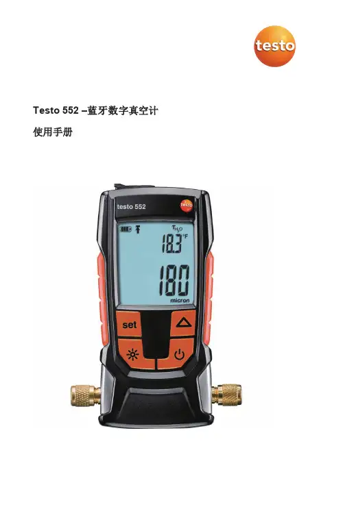
Testo 552 –蓝牙数字真空计使用手册目录目录1 安全和废物处置 (3)1.1 关于本文件 (3)1.2 安全 (3)1.3 废物处置 (4)2 技术数据 (4)2.1 蓝牙模块 (5)3 仪器描述 (6)3.1 用途 (6)3.2 仪器概述 (7)3.3 显示屏概述 (8)3.4 控制键概述 (9)3.5 连接选项概述 (9)4 操作 (11)4.1 连接 (11)4.2 开/关仪器 (12)4.3 开/关背光 (12)4.4 设置单位和自动关机 (13)4.5 显示温度值 (15)4.6 建立蓝牙® 连接 (16)4.7 操作界面说明 (17)4.8 App 选项 (17)4.8.1 设置 “语言” (17)4.8.2 显示教程 (18)4.8.3 显示德图网址 (18)4.8.4 显示应用程序版本 (18)4.9 标准、图形和表视图 (18)4.10 导出读数.................................................................................................. 19s4.10.1 导出Excel (CSV) (19)4.10.2 导出PDF (19)4.10.3 导出图形 (20)4.11 用作Testo 570的传感器 (20)目录5 维护 (21)5.1 更换电池 (21)5.2 清洁仪器 (22)6 提示与协助 (23)6.1 常见问题 (23)6.2 附件和备件 (23)7 EC 符合性声明 (24)1 安全和处置1 安全和废物处置1.1 关于本文档●该说明书属于仪器的一部分●在本仪器的整个使用寿命内请妥善保管本手册●务必使用完整的原厂说明手册●将产品投入使用之前,请仔细阅读本使用说明书并熟悉产品●请特别注意安全说明和警告提示,以免造成人身伤害和仪器损坏1.2 安全一般安全说明●按照产品的预定用途,在技术数据表中规定的参数范围内以正确方式操作本仪器。
蓝牙测试仪安全操作及保养规程一、安全操作规程1.在使用蓝牙测试仪前,必须仔细阅读并理解使用说明书,并按照说明书的指导正确操作设备。
2.在连接设备和电源之前,确保工作环境没有明显的电磁干扰,以避免对蓝牙测试仪产生电磁干扰。
3.使用适当的安全装置将蓝牙测试仪固定在平稳的工作台上,以防止设备因操作中的震动而掉落。
5.在连接设备和电源之前,确保电源的电压和频率与设备的要求相匹配,以避免因电压不稳定而损坏设备或导致安全事故。
6.在操作蓝牙测试仪时,应穿戴适当的防护用具,如工作手套、安全眼镜等,以保护自身的安全。
8.在使用蓝牙测试仪时,应注意周围的工作环境和工作人员的安全,确保设备和周围环境的正常运行。
9.使用蓝牙测试仪时,应根据其使用说明书和具体测试要求,按照正确的操作步骤进行操作,严禁任意调整设备参数和测试参数。
10.操作完成后,应关闭电源,并将设备妥善存放,防止灰尘和湿气进入设备内部,以延长设备的使用寿命。
二、保养规程1.定期检查蓝牙测试仪的电源线、连接线和测量探头的完整性和稳定性,如发现损坏或异常情况,应及时更换。
2.清洁蓝牙测试仪表面的灰尘和污渍,可使用软布轻轻擦拭,避免使用腐蚀性强的清洁剂。
3.注意蓝牙测试仪的存放环境,应远离潮湿、高温、腐蚀性气体等有害环境,以避免设备受损。
4.不使用蓝牙测试仪时,应将设备置于干燥通风的地方,避免灰尘积累。
5.遵循蓝牙测试仪的使用寿命要求,及时进行维修和更换,以保证设备的正常使用。
6.在设备保养期间,应注意不要触摸和更改设备内部的线路和元件,以免出现安全事故。
8.定期对蓝牙测试仪进行校准,确保测试数据的准确性和可靠性。
9.在设备保养期间,应根据设备的使用频率和使用环境,合理制定设备保养计划,并按计划执行。
通过遵守蓝牙测试仪的安全操作规程和保养规程,可以确保设备的安全运行和稳定性能,延长设备的使用寿命,提高工作效率和测试准确性。
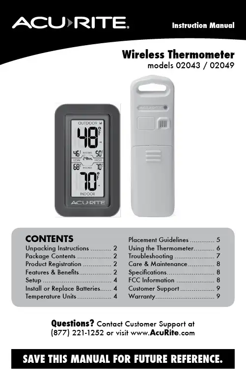
CONTENTS Unpacking Instructions (2)Package Contents (2)Product Registration (2)Features & Benefits (2)Setup (4)Install or Replace Batteries (4)Temperature Units (4)Placement Guidelines (5)Using the Thermometer (6)Troubleshooting (7)Care & Maintenance (8)Specifications (8)FCC Information (8)Customer Support (9)Warranty (9)Wireless Thermometermodels 02043 / 02049Questions? Contact Customer Support at (877) 221-1252 or visit Congratulations on your new AcuRite product. To ensure the best possible product performance, please read this manual in its entirety and retain it for future reference.Unpacking InstructionsRemove the protective film that is applied to the LCD screen prior to using this product. Locate the tab and peel off to remove.Package Contents1. Display unit2. Outdoor sensor3. Instruction ManualFeatures & BenefitsOUTDOOR SENSOR1. Integrated Hanger For easy placement.2. Wireless Signal Indicator Flashes when data is beingsent to the display unit.3. Battery Compartment Cover132DISPLAY UNIT1. S ensor Low Battery Indicator2. C urrent Outdoor Temperature Arrow icon indicates the direction thetemperature is trending.3.R ecord TimespanIndicates viewing records for past 12 hours, 24 hours, 36 hours, 48 hours, or all-time.4. LOW Temperature RecordsLowest temperatures recorded for #3.5. C urrent Indoor TemperatureArrow icon indicates the direction thetemperature is trending.6. D isplay Low Battery Indicator7. H IGH Temperature RecordsHighest temperatures recorded for #3.8. O utdoor Sensor Signal StrengthBACK OF DISPLAY UNIT9. RECORDS ButtonPress to cycle through records (#3).10. Battery Compartment 11. °C/°F ButtonPress to select °C or °Ftemperature units.12. Integrated HangerFor easy placement.Features & Benefits12356478101112Front of Display UnitBack of Display Unit°C/°FInstall or Replace BatteriesAcuRite recommends high quality alkaline batteries for the best product performance. Heavy duty or rechargeable batteries are not recommended.The outdoor sensor requires lithium batteries in low temperature conditions. Cold temperatures can cause alkaline batteries to function improperly. Use lithium batteries in the outdoor sensor for temperatures below -4ºF / -20ºC.Outdoor Sensor1. S lide off the battery compartment cover.2. I nsert 2 x AA batteries into the battery compartment, as shown. Follow the polarity (+/-) diagram in the battery compartment.3. R eplace the battery cover.Display Unit1. S lide off the battery compartment cover.2. I nsert 2 x AA batteries into the battery compartment, as shown. Follow the polarity (+/-) diagram in the battery compartment.3. R eplace the battery cover.Select Temperature UnitsTo select between degrees Fahrenheit (ºF) or Celsius (ºC) temperature units,press the “ºC/ºF” button located inside the battery compartment of the display.batteries properly. Only batteries of the same or equivalent type as recommended are to be used. DO NOT incinerate used batteries. DO NOT dispose of batteries in fire, as batteries may explode or leak. DO NOT mix old and new batteries or types of batteries (alkaline/standard). DO NOT use rechargeable batteries. DO NOT rechargenon-rechargeable batteries. DO NOT short-circuit the supply terminals.°C/°FR E C O R D S - h o l d t o c l e a rPlacement for Maximum AccuracyAcuRite sensors are sensitive to surrounding environmental conditions. Proper placement of both the display unit and outdoor sensor are critical to the accuracy and performance of this product.Display Unit PlacementPlace the display unit in a dry area free of dirt and dust. Display unit stands upright for tabletop use or is wall-mountable.Outdoor Sensor PlacementSensor must be placed outside to observe outdoor conditions. Sensor is water resistant and is designed for general outdoor use, however, to extend its life place the sensor in an area protected from direct weather elements.Hang the sensor using the integrated hang holes or hanger, or by using string (not included) to hang it from a suitable location, like a well covered tree branch. The best location is 4 to 8 feet above the ground with permanent shade and plenty of fresh air to circulate around the sensor.Important Placement Guidelines• To ensure accurate temperature measurement, place units out of directsunlight and away from heat sources or vents.• Display unit and outdoor sensor must be within 165 ft (50 m) of each other. • To maximize wireless range, place units away from large metallic items, thick walls, metal surfaces, or other objects that may limit wireless communication.• To prevent wireless interference, place both units at least 3 ft (.9 m) away from electronic devices (TV, computer, microwave, radio, etc.)Setup is CompleteThe sensor will now synchronize with the display unit. It may take a few minutes for synchronization to complete. Please refer to the troubleshootingsection of this manual if anything appears to be functioning improperly.(50 meters)(165 feet maximum)AT LEAST APARTUsing the ThermometerHigh & Low RecordsThe display will automatically cycle through the high and low recorded values for the past 12 hours, 24 hours, 36 hours, 48 hours, and all-time. To manually cycle through the records, press and release the RECORDS button located in the battery compartment. After 12 seconds of inactivity, the records will return to auto mode.All-time high & low records reflect the minimum and maximum temperature recorded since the unit was powered on, since the batteries were changed, or since it was manually reset (whichever was most recent).To manually reset the high/low records currently being viewed, press and HOLD the RECORDS button, located in the battery compartment for 3-5 seconds.Care & MaintenanceDisplay Unit CareClean with a soft, damp cloth. Do not use caustic cleaners or abrasives. Keep away from dust, dirt and moisture. Clean ventilation ports regularly with a gentle puff of air.Outdoor Sensor CareClean with a soft damp cloth. Do not use caustic cleaners or abrasives.SpecificationsTEMPERATURE RANGE Outdoor: -40ºF to 158ºF; -40ºC to 70ºCIndoor: 32ºF to 122ºF; 0ºC to 50ºCWIRELESS RANGE165 ft / 50 m depending on home construction materials WIRELESS FREQUENCY433 MHzPOWER Display: 2 x AA alkaline batteriesSensor: 2 x AA alkaline or lithium batteriesDATA REPORTING30 second updatesFCC InformationThis device complies with part 15 of FCC rules. Operation is subject to the following two conditions:1- This device may NOT cause harmful interference, and2- This device must accept any interference received, including interference that may cause undesired operation. WARNING: Changes or modifications to this unit not expressly approved by the party responsible for compliance could void the user’s authority to operate the equipment.NOTE: This equipment has been tested and found to comply with the limits for a Class B digital device, pursuant to Part 15 of the FCC rules. These limits are designed to provide reasonable protection against harmful interference in a residential installation. This equip-ment generates, uses and can radiate radio frequency energy and, if not installed and used in accordance with the instructions, may cause harmful interference to radio communications. However, there is no guarantee that interference will not occur in a particular installation. If this equipment does cause harmful interference to radio or television reception, which can be determined by turning the equipment off and on, the user is encouraged to try to correct the interference by one or more of the following measures:• Reorient or relocate the receiving antenna.• Increase the separation between the equipment and the receiver.• Connect the equipment into an outlet on a circuit different from that to which the receiver is connected.• Consult the dealer or an experienced radio/TV technician for help.NOTE: The manufacturer is not responsible for any radio or TV interference caused by unauthorized modifications to this equipment. Such modifications could void the user authority to operate the equipment.This device complies with Industry Canada licence-exempt RSS standard(s).Operation is subject to the following two conditions:(1) This device may not cause interference, and(2) This device must accept any interference received, including interference that may cause undesired operation of the device.At AcuRite, we proudly uphold our commitment to quality technology. Chaney Instrument Co. warrants that all products it manufactures to be of good material and workmanship, and to be free of defects when properly installed and operated for a period of one year from the date of purchase.We recommend that you visit us at for the fastest way to register your product. However, product registration does not eliminate the need to retain youroriginal proof of purchase in order to obtainwarranty benefits.Chaney Instrument Co. warrants that all products it manufactures to be of good material and workmanship, and to be free ofdefects when properly installed and operated for a period ofone year from the date of purchase. Remedy for breach of thiswarranty is limited to repair or replacement of the defectiveitem(s). Any product which, under normal use and service, isproven to breach the warranty contained herein within ONEYEAR from date of sale will, upon examination by Chaney,and at its sole option, be repaired or replaced by Chaney.Transportation costs and charges for returned goods shallbe paid for by the purchaser. Chaney hereby disclaims allresponsibility for such transportation costs and charges. Thiswarranty will not be breached, and Chaney will give no credit for products it manufactures which have received normal wear and tear, been damaged (including by acts of nature), tampered, abused, improperly installed, damaged in shipping, or repaired or altered by others than authorized representatives of Chaney.The above-described warranty is expressly in lieu of all other warranties, express or implied, and all other warranties are hereby expressly disclaimed, including without limitation the implied warranty of merchantability and the implied warranty of fitness for a particular purpose. Chaney expressly disclaims all liability for special, consequential or incidental damages,whether arising in tort or by contract from any breach of thiswarranty. Some states do not allow the exclusion or limitationof incidental or consequential damages, so the above limitation or exclusion may not apply to you. Chaney further disclaims all liability from personal injury relating to its products to the extentpermitted by law. By acceptance of any of Chaney’s products, the purchaser assumes all liability for the consequences arisingfrom their use or misuse. No person, firm or corporation is authorized to assume for Chaney any other liability in connection with the sale of its products. Furthermore, no person, firm or corporation is authorized to modify or waive the terms of this paragraph, and the preceding paragraph, unless done in writing and signed by a duly authorized agent of Chaney. This warranty gives you specific legal rights, and you may also have other rights which vary from state to state.For in-warranty claims: Chaney Instrument Co. 965 Wells St., Lake Geneva, WI 53147Limited One Year WarrantyCustomer SupportAcuRite customer support is committed to providing you with best-in-class service. For assistance , please have the model number of this product available and contact us in any of the following ways:(877) 221-1252 ********************24/7 support at www.AcuRite .com► Installation Videos ► Register your Product ► Instruction Manuals ► Support User Forum ► Replacement Parts► Submit Feedback & Ideas11©Chaney Instrument Co. All rights reserved. AcuRite is a registered trademark of the Chaney Instrument Co., Lake Geneva, WI 53147. All other trademarks and copyrights are the property of their respective owners. AcuRite uses patented technology.Visit /patents for details.Printed in China 02043 INST 121714It’s more than accurate, it’sAcuRite offers an extensive assortment of precision instruments, designed to provide you with information you can depend on toPlan your day with confidence ™.www.AcuRite .comWeather Stations Temperature & Humidity Weather Alert Radio Kitchen Thermometers & Timers Clocks。
测温仪器一一蓝牙体温计方案
蓝牙体温计方案的工作原理利用了温度传感器输出电信号,直接输出数字信号或者再将电流信号(模拟信号)转换成能够被内部集成的电路识别的数字信号,然后通过显示器(如液晶、数码管、LED矩阵等)显示以数字形式的温度,能记录、读取被测温度的最高值。
一般由感温头、量温棒、显示屏和开关等结构组成。
蓝牙体温计方案基本参数
工作电压:3.0V
测试范围:320C--42°C
测试精度:0∙2°C
驱动类型:LCD
校机点:37℃
工作电流:小于IOmA
上下限报警器:无
校机:单点校正:37℃;次数≤300次(该参数IC内部掉电记忆)
传感器类型:热敏电阻
低压检测:一点或两点检测
按键种类:轻触、触摸、拨动
记忆功能:有
背光:三色背光(客户可自定义)
蜂鸣器:有
蓝牙特点:
1)运用蓝牙5.0进行无线数据传输,设备连接手机简单方便;
2)APP软件主界面可同时显示温度、时钟、报警信息和历史数据。
适用范围
1、支持蓝牙5.0、安装K)S系列机型:
2、支持安卓系列机型:
蓝牙5.0并且安装Android的大部分机型。
该蓝牙体温计方案的PCb结构是一个单面板,采用SIC8833单片机作为控制器,加入按键模块、蜂鸣器模块以及电源模块。
PCb结构也可以根据用户的需求定制,能够完全兼容当前市面上各种蓝牙体温计方案的公模外壳,产品最终的形状和款式可以自行设计更改。

手持测温热像仪用户手册.前言本节内容的目的是确保用户通过本手册能够正确使用产品,以避免操作中的危险或财产损失。
在使用此产品之前,请认真阅读产品手册并妥善保存以备日后参考。
符号约定对于文档中出现的符号,说明如下所示。
安全使用注意事项●设备安装使用过程中,必须严格遵守国家或使用地区的各项电气安全规定。
使用匹配且满足SELV(安全特低电压)要求的电源,电源适配器具体要求请参见产品参数表。
●请不要使物体摔落到设备上或大力振动设备,使设备远离存在磁场干扰的地点。
避免将设备安装到表面振动或容易受到冲击的地方。
●严禁将镜头瞄准强热光源,如太阳等高温目标,以免造成镜头或热成像探测器损坏。
●请勿在极热、极冷、多尘、或者高湿度的环境下使用产品,具体温、湿度要求参见产品的参数表。
●设备需存放于干燥无腐蚀性气体环境,电池请勿放置在热源或火源附近,避免阳光直射。
●请妥善保管设备包装材料,以便出现问题时使用原包装包好后寄到代理商或返回厂家处理。
●如果设备工作不正常,请联系购买设备的商店或最近的服务中心,不要以任何方式拆卸或修改设备。
(对未经认可的修改或维修导致的问题,本公司不承担任何责任)。
长期存放的设备,每隔半年应通电检查一次,每次通电时间应不小于3h。
目录产品介绍 (1)1.1装箱清单 (1)1.2产品说明 (1)1.3主要功能 (2)产品外观 (3)2.1产品尺寸 (3)2.2部件介绍 (3)基本操作 (5)3.1充电 (5)3.1.1 通过充电座 (5)3.1.2 通过数据线 (6)3.2开机 (7)3.3关机 (7)3.4主界面 (7)3.5主菜单 (7)3.6调焦 (8)3.7文件导出 (8)3.8升级 (9)3.9操作说明 (9)功能配置 (11)4.1测温配置 (11)4.1.1 单位设置 (11)4.1.2 设置测温参数 (11)4.1.3 规则配置 (13)4.2网络配置 (15)4.2.1 配置Wi-Fi (15)4.2.2 配置热点 (16)4.2.3 配置蓝牙 (17)4.3存储配置 (18)4.3.1 录像配置 (18)4.3.2 抓图配置 (19)4.3.3 查看录像和抓图文件 (20)4.4图像配置 (21)4.4.1 图像温度调节 (21)4.4.2 伪彩设置 (22)4.4.3 融合配置 (23)4.5报警配置 (24)4.6其它设置 (24)系统参数设置 (26)5.1设置显示参数 (26)5.2设备初始化 (26)5.3自动关机 (26)5.4查看设备信息 (27)FAQ (28)常见物质发射率表 (29)产品介绍1.1 装箱清单充电座(×1)适配器(×1)安全箱(×1)主机(×1)电池(×1)USB数据线(×1)说明书(×1)主机已内置镜头盖、电池和SD卡。
CONTENTS Unpacking Instructions (2)Package Contents (2)Product Registration (2)Features & Benefits (3)Setup (4)Install or Replace Batteries (4)Placement Guidelines (5)Using the Thermometer (6)Troubleshooting (7)Care & Maintenance (8)Specifications (8)FCC Information (8)Wireless Thermometermodel 00411/00609SBDIA/00611A3Congratulations on your new AcuRite product. To ensure the best possible product performance, please read this manual in its entirety and retain it for future reference.Unpacking InstructionsRemove the protective film that is applied to the LCD screen prior to using this product. Locate the tab and peel off to remove.Package Contents1.Display unit with tabletop stand2.Outdoor sensor3.Instruction ManualFeatures & BenefitsArrow icon indicates the direction the temperature is trending 2.High Outdoor Temperature Record 3.Low Outdoor Temperature Record 4.High Outdoor Humidity Record 5.Current Outdoor HumidityArrow icon indicates the direction the humidity is trending.6.Low Outdoor Humidity Record 7.Current Indoor TemperatureArrow icon indicates the direction the temperature is trending8.Low Indoor Temperature andHumidity Recordthe humidity is trending 10.High Indoor Temperature andHumidity Record 11.Display Low Battery Indicator 12.Outdoor Sensor LowBattery Indicator13.Outdoor Sensor Signal StrengthOUTDOOR SENSOR14.Integrated Hangerfor easy placement15.Wireless Signal IndicatorFlashes when data is being sent to the display unit 16.Battery Compartment Cover 1723465Main Unit Detachable StandIncluded with the main unit is a detachablestand for tabletop placement.Install or Replace BatteriesAcuRite recommends high quality alkalinebatteries for the best product performance. Heavy duty or rechargeable batteries are not recommended.The outdoor sensor requires lithium batteries in low temperature conditions. Cold temperatures can cause alkaline batteries to function improperly. Use lithium batteries in the outdoor sensor for temperatures below -4ºF / -20ºC.Outdoor Sensor1.S lide off the battery compartment cover.2.I nsert 2 x AA batteries into the batterycompartment, as shown. Follow the polarity(+/-) diagram in the battery compartment.3.R eplace the battery cover.Display Unit1.S lide off the battery compartment cover.2.I nsert 2 x AA batteries into the batterycompartment, as shown. Follow the polarity(+/-) diagram in the battery compartment.3.R eplace the battery cover.Select Degrees Fahrenheit or CelsiusTo select between degrees Fahrenheit (ºF) or Celsius (ºC) temperature units, press the “ºF/ºC” button located on the back of display.batteries properly. Only batteries of the same or equivalent type as recommended are to be used. DO NOT incinerate used batteries. DO NOT dispose of batteries in fire, as batteries may explode or leak. DO NOT mix old and new batteries or types of batteries (alkaline/standard). DO NOT use rechargeable batteries. DO NOT recharge non-rechargeable batteries. DO NOT short-circuit the supply terminals.Placement for Maximum AccuracyAcuRite sensors are sensitive to surrounding environmental conditions. Proper placement of both the display unit and outdoor sensor are critical to the accuracy and performance of this product.Display Unit PlacementPlace the display unit in a dry area free of dirt and dust. Display unit stands upright for tabletop use or is wall-mountable.Outdoor Sensor PlacementSensor must be placed outside to observe outdoor conditions. Sensor is water resistant and is designed for general outdoor use, however, to extend its life place the sensor in an area protected from direct weather elements.Hang the sensor using the integrated hang holes or hanger, orby using string (not included) to hang it from a suitable location, like a well covered tree branch. The best location is 4 to 8 feet above the ground with permanent shade and plenty of fresh air to circulate around the sensor.Important Placement Guidelines•To ensure accurate temperature measurement, place units out of direct sunlight and away from heat sources or vents. •Display unit and outdoor sensor must be within 165 ft (50 m) of each other.•To maximize wireless range, place units away from large metallic items, thick walls, metal surfaces, or other objects that may limit wireless communication.•To prevent wireless interference, place both units at least 3 ft (.9 m) away from electronic devices (TV, computer, microwave, radio, etc.)Setup is CompleteThe sensor will now synchronize with the display unit. It may take a few minutes for synchronization to complete. Please refer to the troubleshooting section of this manual if anything appears to be functioning improperly.(50 meters)(165 feet maximum)Using the ThermometerHigh/Low RecordsHigh an low records reflect the minimum and maximum temperature recorded since the unit was powered on, since the batteries were changed, or since it was manually reset (whichever was most recent).To view the LOW temperature record, press and release the “” button. The “” icon appears on the display next to the low records.To view the HIGH temperature record, press and release the “” button. The “” icon appears on the display next to the high records.To reset the LOW records, press AND HOLD the “” button while viewing the low records. Dashes will display to confirm all low values have been cleared. To reset the HIGH records, press AND HOLD the “” button while viewing the high records. Dashes will display to confirm all high values have been cleared.TroubleshootingCare & MaintenanceDisplay Unit CareClean with a soft, damp cloth. Do not use caustic cleaners or abrasives. Keep away from dust, dirt and moisture. Clean ventilation ports regularly with a gentle puff of air.Outdoor Sensor CareClean with a soft damp cloth. Do not use caustic cleaners or abrasives. SpecificationsTEMPERATURE RANGE Outdoor: -40ºF to 158ºF; -40ºC to 70ºCIndoor: 32ºF to 122ºF; 0ºC to 50ºCHUMIDITY RANGE1% to 99% RHWIRELESS RANGE165 ft / 50 m depending on home construction materials WIRELESS FREQUENCY433 MHzPOWER Display: 2 x AA alkaline batteriesSensor: 2 x AA alkaline or lithium batteriesDATA REPORTING Outdoor data: 31 second updatesIndoor data: 60 second updatesFCC InformationThis device complies with part 15 of FCC rules. Operation is subject to the following two conditions:1- This device may NOT cause harmful interference, and2- This device must accept any interference received, including interference that may cause undesired operation. WARNING: Changes or modifications to this unit not expressly approved by the party responsible for compliance could void the user’s authority to operate the equipment.NOTE: This equipment has been tested and found to comply with the limits for a Class B digital device, pursuant to Part 15 of the FCC rules. These limits are designed to provide reasonable protection against harmful interference in a residential installation. This equip-ment generates, uses and can radiate radio frequency energy and, if not installed and used in accordance with the instructions, may cause harmful interference to radio communications. However, there is no guarantee that interference will not occur in a particular installation. If this equipment does cause harmful interference to radio or television reception, which can be determined by turning the equipment off and on, the user is encouraged to try to correct the interference by one or more of the following measures:• Reorient or relocate the receiving antenna.• Increase the separation between the equipment and the receiver.• Connect the equipment into an outlet on a circuit different from that to which the receiver is connected.• Consult the dealer or an experienced radio/TV technician for help.NOTE: The manufacturer is not responsible for any radio or TV interference caused by unauthorized modifications to this equipment. Such modifications could void the user authority to operate the equipment.This device complies with Industry Canada licence-exempt RSS standard(s).Operation is subject to the following two conditions:(1) This device may not cause interference, and(2) This device must accept any interference received, including interference that may cause undesired operation of the device.。
嘉泰工业蓝牙智能无线透传模块使用手册 低成本快部署稳定可靠
JT-RS-02-100序号规格型号关键参数1波特率 2400 / 9600 / 19200 / 38400 / 57600 / 1152002
数据位8
3
校验位none 4
停止位15接口
RS-232/RS-485 1路6蓝牙
MESH模块7通讯频率
2.4G Hz 8电源
DC 12V 9温度范围
-40~85℃10
特别说明产品适用于RS-485直接传输,RS-232
环境使用需自行配置转接模块。
1、产品外观图2、产品参数
3、接线示意图
图一:产品左侧图二:产品右侧
备注:通常情况下接入RS-485 A端(设备端)与 RS-485 B端(上位机端)即可进行数据传输。
4、出货标准
5、技术支持
⼴广东嘉泰智能技术有限公司 ⼴广东.佛⼭山.南海海⾦金金融⾼高新区夏⻄西国际商务区B4栋三、四楼 ⻩黄⼩小姐139****7588江⼩小姐:139****9518
产品主体一个、DC12V适配电源一个、外置天线一根、接线端子一个、说明书一份、合格证书一份。
⽆无线采集 ,
极速交付 ,
极简上云 !
底层采集:+ BOX 系列列边缘计算管理理器器管理理交付引擎
嘉泰工业蓝牙智能无线采集模块使用手册(JT-RS系列)
JT-RS-02-100采集模块⼴广东嘉泰智能技术有限公司
Guangdong Jiatai Intelligence & Science Co., Ltd。
手持式测温仪使用说明书使用说明书1. 介绍手持式测温仪是一种便携式设备,用于测量物体或人体的温度。
本使用说明书将详细介绍测温仪的使用方法以及注意事项。
2. 外观和功能手持式测温仪外观小巧轻便,方便携带。
主要功能包括:- 温度测量:测温仪配备高精度传感器,能够快速准确地测量物体或人体的温度。
- 温度显示:测温仪配备数码显示屏,可直观显示测量结果。
- 温度单位切换:测温仪支持摄氏度和华氏度之间的切换,可根据需要进行设置。
- 记忆功能:测温仪能够储存多组温度数据,方便日后查询和比对。
3. 使用方法- 步骤一:打开测温仪电源,待仪器自检完成后,数码显示屏将亮起。
- 步骤二:将测温仪对准待测物体或人体,保持距离合适,并按下测量按钮。
- 步骤三:仪器将在短时间内完成温度测量,并在数码显示屏上显示结果。
- 步骤四:若需储存当前测温结果,按下储存按钮,测温仪将记录当前温度数据,方便以后查阅。
4. 注意事项- 避免阳光直射:在使用测温仪时,请避免阳光直射,以免影响测量结果的准确性。
- 保持稳定:在测量过程中,请保持手持式测温仪的稳定,以免因晃动而影响测量结果。
- 符合测量距离:请将测温仪放置在距离测量物体或人体的正确距离上进行测量,以确保结果的准确性。
- 温度单位切换:根据需要,可通过设定菜单进行温度单位的切换。
请确保选择正确的温度单位。
- 清洁与维护:请定期清洁测温仪的探测头,以免灰尘等物质影响测量结果。
若有需求,可使用软布轻擦。
5. 故障排除- 若测温仪无法开启,请检查电池电量是否充足,若电池电量低,请更换电池。
- 若测温结果显示异常或不准确,请检查测量过程中是否受到外界干扰,或者探测头是否干净。
6. 免责声明- 手持式测温仪仅为辅助工具,准确性可能受到环境因素等因素的影响,用户在使用测温仪时请自行判断结果。
- 本厂商不对使用不当、使用失误或由此产生的损害负责。
7. 联系方式如对产品有任何疑问或需要售后服务,请联系客服中心:XXX。
CE_EN300328蓝牙测试系统操作手册CE_EN300328蓝牙测试系统操作手册文件编号:TMC-YBCZ-XX-XXX拟制:秦可嘉日期:审核:日期:批准:日期:工业和信息化部通信计量中心信息产业通信电磁兼容质量监督检验中心目录1介绍 (3)2硬件组成 (3)2.1CE蓝牙测试系统仪表 (3)2.2测试示意图 (3)2.3测试实物图 (3)3EDR测试基本操作 (5)3.1硬件操作 (5)3.2软件操作 (5)4BLE测试基本操作 (7)4.1硬件操作 (7)4.2软件操作 (7)5确认参数 (10)6常见故障及处理方法 (10)1 介绍CE_EN300328蓝牙测试系统(以下简称CE蓝牙测试系统)是以CE的EN300328标准为测试方法指导准则,以R&S厂商的仪表为硬件基础,以自主研发的自动化测试软件为测试手段,能够用来对移动通信终端完成CE标准下蓝牙设备射频指标传导测试的测试系统。
蓝牙测试具体分为EDR与BLE两种模式,测试方式有差异。
本文档所依据的EN300328标准版本基于v1.7.1。
2 硬件组成2.1CE蓝牙测试系统仪表2.2测试示意图EDR测试示意图BLE测试示意图2.3测试实物图EDR测试除功率之外测试例的连线实物图若测试传导功率测试例,将EUT通过N-SMA转接头,通过短射频头直接与CBT32仪表射频口相连即可。
BLE测试实物图3 EDR测试基本操作3.1硬件操作①按系统结构示意图搭建系统,若测试发射传导功率,则按图中的虚线示意连接,三通、频谱仪等;测试发射功率以外的其它测试项,请按照图中实线方法进行连接。
②系统的仪表均使用GPIB接口,通过GPIB-USB线与控制PC相连,控制PC上需安装仪表的相关驱动。
3.2软件操作①选择如图所示的程序。
②选择测试项,其中功率测试case,由于连线方法不一样,只能单独选择测试。
最大发射功率测试case除了常温常压之外,需测试极端条件。
btp-x106用户手册《BTP-X106》是一款多功能蓝牙Spo2仪监测仪。
该仪器配有大屏幕显示器,可以实时显示呼吸率、血氧饱和度、心率、血压等数据。
它具有卓越的多合一性能,可以方便快捷地监测身体的心血管健康,为用户提供物质性的健康检测服务。
本用户手册介绍了BTP-X106的基本功能及操作步骤,希望对您的使用有所帮助。
一、基本功能1、多合一蓝牙SpO2检测仪,能同时检测血氧饱和度,心率,脉搏率,血压等。
2、实时记录您的检测结果,无需担心忘记记录。
3、采用高性能蓝牙通讯技术,可支持手机下载。
4、兼容常用计算机系统(Windows、Mac OS、iOS、Android等),可支持多个设备联适应检测。
5、设备小巧轻便,易于携带、使用和操作。
二、安装步骤1. 找到一个合适的地方,把BTP-X106安装在支撑物上。
2. 将电源附件连接到BTP-X106上。
3. 将蓝牙接收器与支撑物相连,尽量保证蓝牙接收器的距离在7米以内。
4. 打开BTP-X106,将探头连接到它的接口上。
5. 调整联适应检测的参数,看到检测结果则表明安装完成。
三、使用步骤1. 将患者放在测量仪上,按下开始按钮,仪器会开始监控。
2. 实时显示患者的血氧饱和度、心率、脉搏率、血压等数值。
3. 观察数据变化情况,按下结束按钮,仪器测量将会结束。
4. 测量完之后,蓝牙可以与电子设备联通,上传数据到合适的应用即可。
四、注意事项1. 使用之前,请仔细阅读操作说明书,掌握仪器的使用方法,并了解仪器,以免造成不必要的损失和伤害。
2. 如果需要更换探头或更换电池,务必允许专业人员进行处理,防止损坏仪器。
3. 如遇到异常情况,应立刻停止测量,联系厂家以获取有关帮助。
4. 务必将设备置于安全环境下,避免受到潮湿。
5. 禁止将设备与含有水分的物品接触。
MX2300系列户专用蓝牙温湿度记录器MX2301 MX2302 MX2303 MX2304详细说明以及对比概述HOBO MX2301是户外使用,不受天气影响的数据记录器,内置温度和相对湿度传感器。
蓝牙输出数据,更容易、快速设置和下载数据,并且在恶劣的户外环境中可以提供高精度测量。
HOBO MX2302是户外使用,不受天气影响的数据记录器,外置温度和相对湿度传感器。
蓝牙输出数据,更容易、快速设置和下载数据,并且在恶劣的户外环境中可以提供高精度测量。
HOBO MX2303是户外使用,不受天气影响的数据记录器,外置温度传感器。
蓝牙输出数据,更容易、快速设置和下载数据,并且在恶劣的户外环境中可以提供高精度测量。
HOBO MX2304是户外使用,不受天气影响的数据记录器,外置温度传感器。
蓝牙输出数据,更容易、快速设置和下载数据,并且在恶劣的户外环境中可以提供高精度测量。
HOBO MX2305是户外使用,不受天气影响的数据记录器,内置温度传感器。
蓝牙输出数据,更容易、快速设置和下载数据,并且在恶劣的户外环境中可以提供高精度测量。
突出的特性●通过蓝牙低能量方便无线设置和下载数据 (100英尺范围内)●在难以接触到的位置检索数据●视觉警报提醒超出阈值●紧凑,防止风雨,内置安装●通过HOBOmobile APP可以实时查看当前数据,●方便在移动设备共享下载的数据●精度:±0.2℃,±2.5%RH在什么环境数据记录器操作?这个数据记录器在室外环境中运作。
什么测量数据记录器支持吗?MX2301数据记录器支持以下测量:相对湿度和温度技术参数:温度传感器测量范围 MX2301和MX2305内置传感器:-40到70℃(-40到158℉)MX2302外部温度传感器: -40到70℃(-40到158℉)MX2303和MX2304外部温度传感器: -40到100℃(-40到212℉),探针和线缆可以沉浸在50℃(122℉)的淡水中一年精度 ±0.25℃:从-40到0℃(±0.45℉:从-40到32℉)±0.2℃:从0到70℃(±0.36℉:从32到158℉)±0.25℃:从70到100℃(±0.45℉:从158到212℉),备注MX2303和MX2304分辨率 0.04℃(0.072℉)漂移 <0.01℃(0.018℉)RH传感器(MX2301和MX2302)测量范围 0到100% RH,-40到70℃(-40到158℉);环境低于-20℃(4℉)或高于95%RH可能暂时增加最大1%RH传感器误差精度 ±2.5%:从10%到90%(典型),最大±3.5%包括25℃(77℉)时滞后性;±5%:低于10%RH和高于90% RH(典型)分辨率 0.05%漂移 <1%每年典型响应时间(典型90%的变化)温度 MX2301和MX2305内部传感器:17分钟,在空气中移动1米/秒MX2302外部传感器:2分钟30秒,在空气中移动1米/秒MX2303和MX2304外部传感器:3分钟,在空气中移动1米/秒;20秒,在水中RH相对湿度 MX2301:1分钟,在空气中移动1米/秒MX2302:4分钟,在空气中移动1米/秒记录器参数无线电功率 1 mW (0 dBm)传输范围 约30.5米(100英尺)无障碍物无线数据标准 蓝牙智能(蓝牙低能量、蓝牙4.0)记录器工作范围 -40到70℃(-40到158℉)记录间隔 1秒到18个小时记录模式 固定间隔(正常、统计)或破裂存储模式 循环存储或者存满停止启动 立即、按键、固定时间、下区间停止 存满停止、按键、固定时间、下区间时间精度 ±1分钟每月0到50℃(32到122℉)电池 2/3 AA 3.6伏锂电池、用户可更换电池寿命 2年,典型。
八通道炉温测试仪TTrack用户手册◎2014版◎目录前言 (1)重要事项和安全说明 (1)商标和有限责任 (1)测温仪主机接线端口说明 (2)一、安装TTrack软件与USB驱动程序 (3)1.1建议PC配置: (3)1.2软件安装方法: (3)1.3USB驱动程序的安装: (4)1.3.1XP系统USB安装步骤 (4)1.3.2Win7系统USB安装步骤 (6)1.4蓝牙适配器的安装与配置 (10)1.4.1蓝牙适配器的安装 (10)1.4.2蓝牙适配器的配置 (11)1.4.3软件通过蓝牙与设备的连接步骤 (15)二、TTrack软件介绍 (16)2.1工具栏 (16)2.2软件界面功能 (17)2.2.1主机设置 (19)2.2.2设置面板 (20)2.2.3分析设置 (21)2.2.4热电偶设置 (24)2.2.5炉区设置 (25)2.2.6制程设置 (27)2.2.7其他设置 (31)三、炉温测试仪操作步骤 (33)3.1采样间隔设置 (33)3.2进行温度数据测量步骤 (33)3.3数据下载 (34)3.3.1通讯端口选择 (34)3.3.1.1使用USB进行通讯操作 (34)3.3.1.2使用蓝牙进行通讯操作 (34)3.3.2数据下载步骤 (34)3.4打印报表 (34)3.5USB充电 (36)3.6注意事项 (36)3.7蓝牙下载数据注意事项: (37)3.8测温仪初始化步骤 (37)3.9温度校正方法 (40)3.10波峰焊测量规定 (43)四、常见故障 (45)4.1电脑识别不了WT-USB (45)4.2测温结果有偏差 (45)4.3无法进行数据下载或测温曲线严重偏差 (45)4.4电脑识别不了蓝牙 (46)4.5开机指示灯不亮 (46)4.6开机一分钟后红绿灯没有闪烁,一直同时亮 (46)4.7开机后指示灯一开始正常,一段时间后灭了 (46)4.8开机过程中,红灯一直闪烁 (47)附录: (47)技术指标和参数 (47)保修说明: (47)前言TTrack是一个实时测量焊接回流工艺的设备和进行改善优化制程工具。
它拥有更为健全的硬件结构和功能强大的软件平台。
每一次都得到完美的曲线,这些实时数据是当TTrack通过工艺流程时并同时记录在其内部的数据。
当TTrack曲线测量仪通过工艺流程后,内部纪录的数据就自动地无线下载,填补在那些可能由于实时曲线无线传输时发生的中断。
无线下载的特征保证了每一次的曲线测量都是完整的,不需要停下生产再做第二次曲线测量。
TTrack软件的特点容易理解,操作简便。
软件中使用简单,易于理解的术语,配有强大的图表分析界面,能使您快速确定和分析回流焊制程。
重要事项和安全说明感谢您选用TC-80K温度分析仪,使用此温度分析仪时,必须遵守这些安全注意事项,以免发生安全事故和损坏仪器。
(1)在使用或操作此设备之前,请仔细阅读和理解本手册;(2)非本仪器维修人员和未经培训合格的人员切勿随意使用本仪器;(3)高温危险,仪器操作使用时应注意人身安全。
仪器使用时必须置入隔热箱内,以免高温损害仪器;(4)请不要在强电磁干扰源附近使用本仪器;(5)检修时,请关掉电源,以防损坏元器件;(6)仪器使用时,应保持平稳,防止掉落;(7)仪器使用后,请及时将测温仪主机拿出隔热箱即拿出保温盒等待测温仪主机与保温盒冷却后,请及时将仪器放回仪器箱内,以免意外损坏仪器。
(8)请注意要在测温仪主机和保温盒冷却之后才可以进行重复测试。
(9)请不要自行更换电池,我们的电池是专门定做的,具有防爆、可充电并无记忆效应等优点。
如果自动更换电池,电池不匹配,可能会爆炸或是对测温仪主机的寿命造成影响。
(10)测温范围0-400℃过炉时间不能超过10分钟,建议5-7分钟左右。
如果测温范围在400-500℃,建议过炉时间为1分钟。
商标和有限责任版权所有本公司对产品拥有一切法定权利、所有权和利益,包括但不限于服务中的任何知识产权(无论该等权利是否已经登记,也不论该等权利在世界的何等地方存在)。
服务可能包括本公司指定为保密的信息,未经本公司事先书面同意,禁止对产品软件以及本文档的部分或全部内容进行转录、复制、翻印或翻译。
用户在使用本产品复制此类内容时,自行承担复制行为的法律责任。
本公司以及第三方软件的服务许可证协议在安装激活、产品本身或者在软件升级当中已经声明,敬请关注。
制造商、进口商恕不承担因意外(包括人为或其它不可抗力)造成的产品损坏的责任。
本公司不承担由此文档的错误或疏漏引起的任何责任,本公司将继续为产品开发提供新的功能,此文档内容如有变动恕不另行通知。
由于产品功能的不断更新,您手中的用户手册可能会与实际操作有所出入。
最新用户手册请联系本公司索取。
此用户手册更新日期为2014年11月3日测温仪主机接线端口说明电源开关USB 接口工作状态指示灯电池低压指示灯充电指示灯温度采样/停止按纽天线热电偶插槽一、安装TTrack软件与USB驱动程序1.1建议PC配置:*300MHz处理器/256Mb RAM*1Gb可用的存储空间(存储产品的历史纪录)*SVGA video1024x768分辨率,16-bit color(或更高分辨率会更好)*1个可用的USB端口*操作系统:Microsoft Windows2000,XP语言TTrack软件支持如下语言:英文/简体/繁体注:繁体语言只有在繁体Window操作系统下才能完好的支持。
1.2软件安装方法:在安装TTrack软件之前,为了避免软件冲突你可将所有其它正在运行的应用软件关闭。
这是一个很好的习惯当你在装任何一个软件。
安装步骤:1.光盘放进光驱。
2.打开光盘中的文件,双击TTrack.exe。
3.根据屏幕上的提示安装软件。
选择“I accept the terms in the license agreement”,单击【Next>】最后单击【Finish】,完成TTrack软件的安装。
1.3USB驱动程序的安装:注意:USB的驱动程序与电脑系统有关,window XP与windows7的驱动不同,请与供应商确认1.3.1XP系统USB安装步骤1.当炉温测试仪主机第一次与计算机连接后,计算机扫描到新硬件会弹出下图所示的窗口。
选择“从列表或指定位置安装(高级)”后单击【下一步】浏览光盘中的“WT-USB驱动程序”文件后“确定”,单击【下一步】完成安装。
出现如上图所示窗口单击【完成】,即安装USB驱动程序完毕。
1.3.2Win7系统USB安装步骤1.炉温测试仪主机开机,用测温仪USB线将测温仪主机连接到电脑。
2.在“计算机”单击右键,选择“属性”出现如下图1.3.1图1.3.13.在图1.3.1单击“设备管理器”出现如图1.3.2图1.3.24.图1.3.2中“未知设备”是USB驱动,如图1.3.2未出现“未知设备”则单击改图中“扫面硬件改动”则会弹出“未知设备”5.在“未知设备”上单击右键选择“更新驱动程序”弹出如图1.3.3所示图1.3.36.单击图1.3.3“浏览计算机以查找驱动程序软件”出现如图1.3.4,单击图1.3.4“浏览”找到软件件光盘中“Win7系统USB驱动程序”安装文件夹,单击“确定”,勾选“包括子文件夹”,再单击“下一步”,如出现如图1.3.5所示。
图1.3.4图1.3.57.单击图1.3.5“始终安装此驱动程序软件”,如果杀毒软件阻止安装则要选择允许安装即可。
等待安装结束出现如图1.3.6图1.3.6USB驱动安装成功USB安装成功后,在设备管理器可以看到“WT’s device drivers”,而且打开软件在主机面板显示温度和电压。
1.4蓝牙适配器的安装与配置1.4.1蓝牙适配器的安装将USB蓝牙适配器连接到Windows XP,Windows XP SP2可以提供通用的软件与驱动支持不需要另外安装驱动。
插入USB蓝牙适配器后,WINDOWS会自动安装XP自带的通用蓝牙驱动程序,安装完成后,在XP的设备管理器中应该看到已经安装好的蓝牙适配器。
自动安装完毕后,在设备管理器可以看到Bluetooth Radios设备已经安装好。
1.4.2蓝牙适配器的配置鼠标右键电脑桌面任务栏上的蓝色蓝牙图标选择“添加Bluetooth设备”,此时要确保炉温测仪器电池足够,并且是处于开机状态下。
选择“添加Bluetooth设备”后弹出如上图所示的窗口,单击“添加”。
在“我设备已经设置并且准备好,可以查找(F)”前打勾并单击“下一步”。
进入搜索窗口,自动搜索附近存在的蓝牙设备。
当搜索完毕时,选择要匹配的蓝牙设备后单击“下一步”。
选择“让我选择自己的密钥(L)”,输入蓝牙的PIN码,出厂一般默认为:“00000000”,输入完毕单击“下一步”。
此时WINDOWS会进行连接,配对,并安装虚拟串口,安装完成后,右下角会出现安装新设备的提示。
安装完成如下图:此时,WINDOWS对新设备分配了2个串行端口。
传出COM端口:COM23传入COM端口:COM24点击“完成”,虚拟串口的安装完毕。
值得注意的是:当蓝牙适配器插到不同电脑或者不同USB端口时,有可能分配的“传出COM端口”和“传入COM端口”有可能不同,我们只需记住传出COM端口的端口号(注意端口号与电脑有关,应根据实际情况而记)。
在设备管理器中,也可以看到安装配置好的虚拟串口的情况。
1.4.3软件通过蓝牙与设备的连接步骤按照以上步骤安装好蓝牙,测温仪上电,打开TTrack软件如图1所示图1单击【搜寻】,出现如图2所示表示软件通过蓝牙与设备连接成功图2二、TTrack软件介绍2.1工具栏●:新建温度分布曲线文档;●:打开已经保存的温度分布曲线文档。
●:保存温度分布曲线文档到磁盘中。
●:启动温度测试仪温度测量操作。
●:停止温度测试仪测量或者数据下载操作。
●:从温度测试仪中下载数据。
●:通过蓝牙温度测试仪中下载数据。
●:显示/隐藏坐标指示。
●:放大局部的温度分布曲线。
在该模式下,点击鼠标右键可以恢复显示完整的温度分布曲线图。
●:拖动温度分布曲线。
●:添加标注,单击该按钮后在温度曲线面板上右键可添加相应的标注。
●:编辑温度曲线,单击该按钮后可在曲线面板拉动曲线。
注:该按钮只能在登陆成管理员才可用。
●:显或隐对齐工具。
●:显示/隐藏温度曲线的三维图。
●:三维图填充。
●:测温曲线平滑切换。
●:显示/隐藏“温度曲线”面板。
●:显示/隐藏“设置”面板。
●:打印预览。
●:打印。
●:管理员登陆/退出;默认密码为:0。
●:关于软件版本。
●:软件退出。
2.2软件界面功能打开TTrack软件,界面如下图所示,主界面中主要由设置面板、温度曲线窗口以及数据面板组成其它制程主机属性分析热电偶炉区温度曲线面板数据面板2.2.1主机设置●机器号:默认机器号是0x88一般不做设置●内部温度和电压监控:显示当前仪器内部温度和供电电压●连接状态与设备消息:当炉温测试仪连接到电脑时,“连接状态”指示灯显示绿色表示TTrack主机与电脑通讯正常。