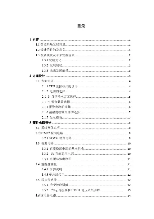
鸡舍灯光控制器系统设计
- 格式:doc
- 大小:1.10 MB
- 文档页数:20
目录1 引言 (1)1.1智能鸡场发展背景 (1)1.2设计的目的及意义 (1)1.3发展现状及未来发展前景 (2)1.3.1发展变化 (2)1.3.2 发展现状 (2)1.3.3 未来发展前景 (3)2 方案设计 (4)2.1 方案论证 (4)2.1.1 CPU主控芯片的设计 (4)2.1.2 电源的选择 (4)2. 1. 3 自动喂水方案选择 (5)2. 1. 4 喂食装置选择 (6)2.1.5报警电路的选择 (6)2.1.6温湿度检测原件的选择 (7)2.1.7 显示模块 (7)3 硬件电路设计 (8)3.1 系统整体说明 (8)3.2 STM32控制电路 (9)3.2.1 STM32硬件电路 (9)3.3 电源电路 (10)3.3.1 直流稳压电源的基本组成 (10)3.3.2 5v直流稳压电源 (10)3.3.3 电源总体电路图 (11)3.4 温湿度测量 (11)3.4.1 引脚说明 (11)3.4.3单总线接口 (12)3.5 压力传感器 (12)3.5.1 应变效应讲解 (12)3.5.2 20kg传感器和HX711电压采集讲解 (13)3.6继电器电路 (14)3.7光电耦合器选择 (14)3.8驱动三极管的选择 (15)4 软件设计 (16)4.1 养鸡场控制系统主流程图 (16)4.2 STM32底层驱动 (16)4.3 按键程序 (17)4.3 报警电路软件设计 (18)5 调试过程 (20)5.1硬件调试 (20)5.2软件调试 (20)5.3温湿度、光照调试 (20)总结 (22)参考文献 (23)附录一 (24)附录二 (25)致谢 (34)摘要随着社会的不断进步,科学技术的不断提高,智能化已经逐渐占领市场,比如智能家居、智能温室大棚、智能机器人等,自动化、机械化、智能化的设备已逐渐代替了传统的体力劳作成为新型的劳动力,这种劳动力使人们的生活更加便利,也在一定程度上减少了人们的工作量,节约了大量时间。
鸡舍灯光控制器学院:能动学院年级专业:2008级机械电子工程学号:********姓名:樱凝指导教师:中国甘肃兰州目录中文摘要 (1)英文摘要 (1)引言 (2)1.方案论证 (2)2.系统设计2.1系统功能 (2)2.2总体设计 (3)2.2.1系统框图 (3)2.2.2各模块框图 (3)2.3原理简述 (4)2.3.1补光原理 (4)2.3.2电路原理 (4)2.4器件选择 (4)3.电路设计3.1直流稳压电源 (5)3.1.1直流稳压电源电路图 (6)3.1.2器件选择和参数计算 (6)3.2光照控制电路3.2.1光照控制电路电路图及原理 (6)3.2.2器件选择和参数计算 (6)3.3时钟控制电路3.3.1电子钟电路 (7)3.3.2逻辑控制电路 (9)3.4主电路3.4.1主电路图 (13)3.4.2说明 (13)3.5整体电路图 (13)3.6结果分析 (14)3.6.1直流稳压电源模块 (14)3.6.2CP模块 (15)3.6.3电子钟模块 (15)3.6.4控制模块 (15)4.结论 (16)参考文献 (17)摘要对鸡舍灯光控制方式进行分析,综合其优缺点提出一种合理的控制模式。
运用电子技术相关知识设计了鸡舍灯光自动控制电路。
采用光照控制电路和时钟控制电路组合控制,实现了对鸡舍进行自动补光。
解决了不同天气、不同季节鸡舍灯光控制复杂的问题。
核心部分是控制电路,其优劣决定了补光的合理性与准确性等整体性能。
设计过程中采用了加拿大Interactive Image Technologies Ltd.公司的设计软件Multisim7.0,通过电脑仿真来设计电路图,并测试其各个模块的功能,最终实现设计要求。
关键词:鸡舍补光;光照控制;时钟控制AbstractSheds light on the analysis of control, its advantages and disadvantages of the integrated control of a reasonable model. Knowledge of the use of electronic technology designed sheds light automatic control circuit. Illumination using the clock control circuit and control circuit combination of control, the realization of automatic sheds light up. Solution of different weather, different seasons sheds light control of complex issues. The core of the control circuits, their advantages and disadvantages determine the reasonableness of premium light, such as overall performance and accuracy. The design process used in Canada, Interactive Image Technologies Ltd. The company's design software Multisim7.0, through computer simulation to design schematics, and test the functions of its various modules, and ultimately the design requirements.Keywords: sheds light up; light control; clock control引言鸡舍的灯光控制是蛋鸡饲养中的重要一环。
鸡舍智能补光器的设计(陕西理工学院物理与电信工程学院电子信息工程专业,级班,陕西汉中723003)指导教师:【摘要】在鸡的养殖过程中,鸡舍环境对鸡的生长和产蛋质量影响较大,鸡舍的灯光控制是蛋鸡饲养中的重要一环。
本设计以STC89C52单片机为主控设计了时钟控制与光照控制相结合的鸡舍补光电路。
其中,实时光照监控模块能够实现不同天气,不同季节鸡舍灯光的实时监测;时钟电路模块设定冬/夏两个不同季节的固定补光时间段,以使鸡舍内的光照强度保持恒定。
有效的促进了雏鸡的生长,蛋鸡的产蛋率及质量得以提高。
并能根据鸡生长的不同阶段调节补光时间段。
并以12864LCD液晶能够实时显示夏季补光时间、冬季补光时间、自动补光时间、休息时间(通过切换模块)。
与高端的鸡舍灯光控制器相比,虽然功能较少,但实现了基本的补光功能,满足了实际需要,同时成本较低,基本上能够适合于中小规模的养鸡场。
【关键词】固定补光;实时监控;光照控制;时钟控制The design of Intelligent lighting device on pheasantry(Class , , School of Physics and Electronic Information Engineering,Electronics and Information Engineering Dept,Shaanxi University of Technology,Han zhong 723003,Shaanxi)Tutor:[Abstract]In the process of chicken breeding, there have an influence on the growth of chicken and egg quality by pheasantry environment, so the light control is an important measure in laying hens breeding. This design using STC89C52 MCU as the main control core and designed a light control circuit on pheasantry combine with time and illumination control .Among them, the real-time monitoring module can realize light real-time monitoring in the different weather or different seasons; Clock circuit module set fixed fill light time between two different seasons of winter/summer, so that make the light intensity constant in the henhouse. Promoting the growth of the chicks effectively, improving the rate of laying hens and quality. And can adjust the light according to the different stages of chickens grow period. And 12864 LCD can display real-time fill light summer time and winter time, automatic light time, and rest time (by switching module). Compared with the high-end light controller, though less functional, but realized the basic function of fill light, meet the actual needs, at the same time, lower cost, basically can be suitable for small and medium-sized chicken farm.[Keywords] light control; clock control; fixed fill light; real-time monitoring.目录1 引言 (1)1.1课题背景 (1)1.2国内外研究现状 (1)2 设计思路 (3)2.1设计要求 (3)2.2方案论证 (3)2.3设计内容 (3)2.4设计方案 (4)3模块电路设计 (6)3.1电源电路设计 (6)3.2过零检测电路 (6)3.3光控检测电路 (7)3.3.1 光敏电阻工作原理 (7)3.3.2 ADC0832芯片介绍 (7)3.3.3 光控检测工作原理 (8)3.4时钟控制电路 (8)3.4.1LCD12864介绍 (8)3.4.2 DS1302芯片介绍 (9)3.4.2单片机芯片STC89C52原理 (9)3.5晶振电路 (13)4软件设计 (14)4.1编程软件简介 (14)4.2系统软件调试 (15)5 硬件安装与调试 (17)5.1系统硬件调试 (17)5.2系统整体调试 (18)总结 (21)致谢 (22)参考文献 (23)附录A 外文文献 (24)附录B 中文翻译 (28)附录C 主电路原理图 (31)附录D 主电路PCB图 (32)附录E 实物图 (33)附录F 元器件清单 (34)附录G C语言源程序 (35)1 引言1.1 课题背景光照时间及光照强度与鸡的代谢、活动及行为关系密切。
·83·绪论实验研究表明,光照对雏鸡有很大的影响,光线中的紫外线明显可促使鸡体的7-脱氢胆固醇转为维生素并有效促进雏鸡的骨骼的快速发育、同时适当增加光照时间还可以延长雏鸡采食时间,加快雏鸡生长速度,因此正常的光照对雏鸡的生长发育必不可少,所以研究养鸡场中智能光照设计很有必要。
1.光照对雏鸡生长发育的影响我们首先分析光照的时间。
在光照强度适中的情况下,光照时间过短,影响雏鸡的正常发育,雏鸡的形体成熟和性成熟都会滞后。
光照时间过长会使雏鸡提前性成熟,在鸡体还没有达到体成熟前就性成熟,会使鸡产蛋提前,产蛋高峰持续的时间缩短,蛋重减少,所以必须光照适中。
其次,光照的强度。
光照强度过强易使雏鸡产生啄癖或打斗,过弱对雏鸡的生长发育不利。
2.光照对产蛋鸡的影响在养殖场里,光照的时间与强度对产蛋鸡的影响是很大的,所以必须采用人工干预的方法。
在适宜的强度下,光照时间越长,产蛋性能就越好。
光照过长则易使蛋鸡产生产蛋疲劳症,造成产蛋鸡丧失产蛋性能。
研究表明,光照强度为32~65勒克斯为宜,过弱会使蛋鸡的生产性能有所下降,过强会使蛋鸡产生凶猛、啄毛等不良行为。
这样我们可以在养殖场设计一套自动化控制的照明装置以适应产蛋鸡生长与产蛋。
同时利用单片机调节好光照,有利于肉鸡在夜间寻觅到水和饲料,因此可以增加饮食量,促进产蛋鸡的体重增重。
过高的光照强度会使其活动增加,消耗热能而导致料肉比不合理。
养殖场可以用黑布遮挡自然光线的强度。
光照通常是采用23小时光照、1小时黑暗的模式,这也是为了防止突然停电引起应激的一项措施。
3.灯光控制总体设计养殖场里以AT89S52单片机为主,再巧妙地利用热释红外传感器检测家禽,同时设计一个光敏三极管来检测环境光的强度;控制养殖场里开灯时间与周期,同时可以感应家禽的移动,通过对产蛋鸡的在下方是否存在信号进行监控和智能判断,实现对养殖场的产蛋鸡是否移动到灯光的下方进行智能控制。
根据白天还是夜间,及时调整光照强度,感应系统由传感器感应信号,再送入单片机进行处理,再由单片机控制养殖场电路。
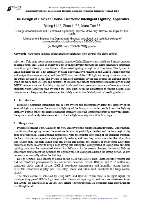
Advances in Engineering Research (AER), volume 61International Conference on Mechanical, Electronic, Control and Automation Engineering (MECAE 2017)The Design of Chicken House Electronic Intelligent Lighting ApparatusBiqing Li 1, b, Zhao Li 2, a, Xiuru Tan 1, b1College of Mechanical and Electronic Engineering, Hezhou University, Hezhou Guangxi 542899,China2Management Engineering Department, Guangxi vocational and technical college ofcommunications, Liuzhou Guangxi 530000, Chinaa****************,b****************Keywords: Automatic lighting; photosensitive resistance, light control, the clock control. Abstract. This page proposed an automatic henhouse light filling system which used microcomputer as main control unit. It can be achieved light up in the daytime through the photoconductive resistance induction light intensity is insufficient; illuminated lighting at night in a fixed time. The System to sense and measure the light intensity by using photosensitive resistance and LM358 , then compares and output the measured value, and then SCM can control the LED light according to the variation of the output measured value. The System to achieved electricity saving and control the lighting time by using the clock chip DS1302 and batteries, to measure the indoor temperature and humidity by using DHT11 temperature and humidity chip, and to showed the current environment of temperature and humidity values and real time by using the 1602 chip. With the advantages of simple design, easy maintenance, cheap cost, the system can be widely used in the field of poultry breeding industry.1.IntroductionHenhouse electronic intelligence fill-in light system can automatically detect the intensity of the external light and control the automatic lighting of the lamp, so as to let people know the lighting intensity. People can set the range of lighting intensity; once the lighting intensity is below this range, the system can directly take measures to make the light intensity be within this range.2.Design ideaPrinciple of filling light. Chickens are very sensitive to the changes in light intensity. Under natural conditions, when spring comes, the sunshine duration is gradually extended, and the hens begin to lay eggs and reproduce. When autumn approaches, with the gradual shortening of the sunshine duration, the hens’ abilities to reproduce also gradually reduce, and then they moult one after the other, thus stop laying eggs. Modern laying hens still retain this nature, the changes of solar terms have great impacts on them. In order to keep a high laying rate during the laying period of laying hens, the daily lighting time must be maintained above 14 ~ 16 hours. As the season changes, the natural lighting sometimes cannot meet the demands for lighting time of laying hens during the laying period, so it is necessary to manually adjust the lighting.Design scheme. This scheme is based on the SCM STC89C52 chip. Photosensitive resistor and LM358 constitute photosensitive resistor access detection circuit. DS1302 and 2032 button cell constitute clock control circuit. DHT11 constitutes temperature and humidity testing circuit. LCD1602 constitutes display part. The relay, triode and 100W bulb constitute the lamp control circuit.The clock control is achieved by using SCM and DS1302: when there is an input signal, the corresponding pin of SCM is high level; when there is no input signal, and the time is between 4a.m. and 10p.m., the pin of SCM is the low level signal (set output signal), if not in this time period, the pin is still high level.After the SCM sends a starting signal, DHT11 switches from low-power mode to high-speed mode; after the host sends out the starting signal, DHT11 begins to send a response signal and 40bit data, and also trigger a signal acquisition. Select reading partial data, under this mode, DHT11 receives the starting signal and then triggers a temperature and humidity acquisition, and displays the value on the LCD 1602. If not receiving the starting signal sent by the host, DHT11 will not take the initiative to acquire temperature and humidity. After the data acquisition is completed, it will automatically switch to the low-speed mode.3.Hardware circuit designThe design is composed of SCM minimum system, light-operated detection circuit, clock control circuit, temperature and humidity induced circuit and display circuit.The system has no special requirements for the processing speed, so it choose STC89C52 SCM produced by STC Company. STC89C52 adds online debugging function, thus the development of this chip does not require expensive hardware emulator, and it realizes real-time emulation. All resources can be used by the user and can be programmed online or in the system. The design uses P0 port, P1 port, P2 port and P3 port of SCM, which realizes data reading and writing as well as LED lighting control. P3 port is used as the download port.Reset circuit. When the system is in normal working condition, after the oscillator is stable, if RST pin has a high level and maintains 2 machine cycles (24 clock cycles), the CPU can respond and reset the system. Reset is divided into manual reset and power-on reset. The system of this design adopts power-on automatic reset and a normally open button is connected in the circuit in parallel, press the switch for a certain period of time, it will be able to make the RST pin to a high level so as to reset the SCM. The reset circuit of the system is shown in Figure 1.Figure 1 Reset circuitCrystal oscillator circuit. There is a high-gain inverting amplifier used to form the oscillator inside STC89C52. The signal produced by the oscillator is sent to CPU to be used as CPU clock signal, so as to drive the CPU to generate the machine cycle that executes the command function. The SCM pins XTAL1 and XTAL2 are the input and output terminals of the amplifier.The oscillation circuit of the system is shown in Figure 2.Figure 2 Crystal oscillator circuitThe circuit consists of two parts: signal acquisition and signal processing.(1) Signal acquisition part of lighting intensity: Photosensitive resistor is used as signal acquisition device. Photosensitive resistor is a kind of photoelectric device based on photoconductivity effect. When there is no light, photosensitive resistance value (dark resistance) is very large, and the current (dark current) in the circuit is very small. When exposed to light, the conductivity of semiconductor materials increases, and the resistance decreases. The resistance value increases with the lighting decreases.(2) Signal processing part: This design uses the integrated voltage comparator LM358 as the core component for signal processing. Two lighting states of intensive light and darkness are converted to two voltage values V1 and V2, which are regarded as the input voltage of the comparator; the twocomparators set two reference voltages Vref1 and Vref2. The working process analysis is as follows: when the lighting is strong, V1> Vref1>Vref2, the output voltages of the two comparators are (5V, 0V). When the lighting is dark, V2< Vref2 < Vref1, the output voltages of the two comparators are (-5V, 5V). Thus, it completes the conversion from analog signal to digital signal.4.Software designThe program flow is shown in Figure 23. When the circuit begins to run, the program is initialized, and the first line of LCD shows the student number: 0910618014, the second line shows the name: HU XI. Then, the first line shows the time, and the second line shows the temperature and humidity. After the time program starts to run, the time display changes per second (synchronize with the seconds). When the second shows 60, the second returns to zero, minute plus one; when the minute shows 60, the minute returns to zero, hour plus one; when the hour shows 24, the hour returns to zero.5.ConclusionThis design only stimulates to control the henhouse light, so it just uses some light-emitting diodes to simulate the light used in the henhouse, and the 5V low-voltage power source is used to stimulate the 220V mains supply that drives the light in the henhouse. In reality, we can use 220V mains supply instead of the 5V power supply and the ordinary lighting lamp used in the henhouse instead of the light-emitting diodes. Besides, we can control the circuit lighting with the relay. Acknowledgements2016 The project of improving the basic ability of young teachers in Colleges and universities in Guangxi: “Design and development of elect ronic commerce platform of agricultural products based on Semantic Technology” (No, KY2016YB455).2015 college students' innovative training program: “Research on the application of value added travel experience in the mobile terminal of the ‘ethnic custom travel’ in Guangxi” (No 201511838070); & “The design and development HeYuanTong Campus Mobile Phone APP based on Android” (No 201511838034).Project of scientific research and technology development project of Hezhou: “Design and implementation of agricultural products e-commerce platform based on Semantic Technology” (No, Hekeneng 1506006).References[1] B.Q LI, Y.F LING, H.Y ZHANG, S.Y ZHENG: The Design And Realization of Cherry TomatoHarvesting Robot Based on IOT. International Journal of Online Engineering, 12(12), 23, (2016).[2] B.Q LI, W.L GUAN, S.Y Zheng, X.G Yue: OPTIMISATION DESIGN OF CORN PRECISIONSEEDER BASED ON MULTI-ROUTE AND MULTI-CHANNEL CONTROL. JOURNAL OF THE BALKAN TRIBOLOGICAL ASSOCIATION, 21(4A), 1215, (2015).[3] B.Q Li, Et Al, The Design Implementation Of The APP Of Experiencing Guangxi Folk Custom,In: PROCEEDINGS OF THE 2016 INTERNATIONAL CONFERENCE ON ECONOMICS AND MANAGEMENT INNOVATIONS, Wuhan, China, 2016, PP.47-50.[4] B.Q Li, Et Al, Intelligent Control Management System and Its Application, In: PROCEEDINGSOF THE 2016 INTERNATIONAL CONFERENCE ON ECONOMICS AND MANAGEMENT INNOVATIONS, Wuhan, China, 2016, PP.68-71.[5] B.Q Li, Et Al, Design And Implementation Of Tanks War Game Based On The Android Platform,In: PROCEEDINGS OF THE 2016 2ND WROKSHOP ON ADVANCED RESEARCH AND TECHNOLOGY IN INDUSTRY APPLICATIONS, Dalian, China, 2016, PP.963-966.。
鸡舍灯光控制器学院:机电学院年级专业:2006级机械电子工程学号:********姓名:指导教师:中国陕西杨凌目录中文摘要 (1)英文摘要 (1)引言 (2)1.方案论证 (2)2.系统设计2.1系统功能 (2)2.2总体设计 (3)2.2.1系统框图 (3)2.2.2各模块框图 (3)2.3原理简述 (4)2.3.1补光原理 (4)2.3.2电路原理 (4)2.4器件选择 (4)3.电路设计3.1直流稳压电源 (5)3.1.1直流稳压电源电路图 (6)3.1.2器件选择和参数计算 (6)3.2光照控制电路3.2.1光照控制电路电路图及原理 (6)3.2.2器件选择和参数计算 (6)3.3时钟控制电路3.3.1电子钟电路 (7)3.3.2逻辑控制电路 (9)3.4主电路3.4.1主电路图 (13)3.4.2说明 (13)3.5整体电路图 (13)3.6结果分析 (14)3.6.1直流稳压电源模块 (14)3.6.2CP模块 (15)3.6.3电子钟模块 (15)3.6.4控制模块 (15)4.结论 (16)参考文献 (17)致谢 (18)摘要对鸡舍灯光控制方式进行分析,综合其优缺点提出一种合理的控制模式。
运用电子技术相关知识设计了鸡舍灯光自动控制电路。
采用光照控制电路和时钟控制电路组合控制,实现了对鸡舍进行自动补光。
解决了不同天气、不同季节鸡舍灯光控制复杂的问题。
核心部分是控制电路,其优劣决定了补光的合理性与准确性等整体性能。
设计过程中采用了加拿大Interactive Image Technologies Ltd.公司的设计软件Multisim7.0,通过电脑仿真来设计电路图,并测试其各个模块的功能,最终实现设计要求。
关键词:鸡舍补光;光照控制;时钟控制AbstractSheds light on the analysis of control, its advantages and disadvantages of the integrated control of a reasonable model. Knowledge of the use of electronic technology designed sheds light automatic control circuit. Illumination using the clock control circuit and control circuit combination of control, the realization of automatic sheds light up. Solution of different weather, different seasons sheds light control of complex issues. The core of the control circuits, their advantages and disadvantages determine the reasonableness of premium light, such as overall performance and accuracy. The design process used in Canada, Interactive Image Technologies Ltd. The company's design software Multisim7.0, through computer simulation to design schematics, and test the functions of its various modules, and ultimately the design requirements.Keywords: sheds light up; light control; clock control引言鸡舍的灯光控制是蛋鸡饲养中的重要一环。
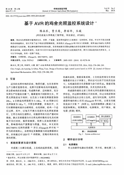
目录绪论 (5)引言 (6)1鸡舍光强测控系统整体描述 (7)1.1 灯光控制总体思想 (7)1.2 灯光控制方案分析 (8)2 硬件电路设计 (9)2.1 控制核心模块 (9)2.2 鸡舍光照强度检测模块 (9)2.2.1 光敏电阻功能简述 (9)2.2.2 AD转换模块 (12)2.3 继电器灯控模拟模块 (13)2.4 复位电路和晶振模块 (13)2.6 1602显示模块 (14)3系统主程序流程图 (17)结论 (18)参考文献 (18)插图索引图1半开放式鸡舍灯光图 (6)图2 设计方案流程图 (7)图3 系统方框设计图 (8)图4 主控制系统图 (9)图5光敏电阻的结构图 (10)图6光电导体严密封装在带有玻璃的壳体 (10)图7 伏安特性 (10)图8 光照特性 (11)图9 响应时间和频率特性 (11)图10 光敏电阻 (11)图11 暗电流 (11)图12 A/D电路设计 (12)图13 ADC0804引脚图 (12)图14 光采集电路图 (13)图15继电器灯控模拟图 (13)图16 复位电路 (14)图17晶振电路 (14)图18显示模块 (14)图19 系统主程序流程图 (17)摘要鸡舍光照强度对鸡的生长、发育、产蛋量、蛋的大小和蛋壳厚度都有影响。
为此, 针对开放式蛋鸡舍结构的特点, 设计开发了开放式蛋鸡舍光照控制系统。
该系统以单片机AT89C51为微控制器, 选用光敏电阻进行光采集, 通过继电器控制鸡舍光源, 同时将光敏电阻采集的光强数据经过AD转换传送到单片机进行数据比较分析。
该系统根据光采集电路采集的光强数据, 通过一定算法,能够实现鸡舍内的光照度按照设定值自动调控。
试验结果表明: 对开放式蛋鸡舍试用的光照度调控系统进行光照调控,既可以保证蛋鸡的光照要求, 又可以节约电能, 具有推广价值。
关键词: 光照控制;蛋鸡舍;AT 89C51;光敏电阻;继电器; ADC0804AbstractThe hen house light intensity to the chicken growth, development, produces the size of an egg, and shell thickness are having an impact. Therefore, to open up the characteristics of the structure factor, designing and developing the open up layers upon control system . The system on the single chip computer AT89C51 for micro controller, choose photoconductive resistance to light acquisition, through the relay control sheds light source, and the light of the collection will photoconductive resistance strong data after AD transform MCU is sent to the data comparison analysis. The system according to light the light intensity acquisition circuit gathering data, through some algorithm, can realize the hen house according to the light within the set value to be automatic control. The test results show that: to open up the light control factor trial system for light regulation, which can ensure the layers upon request, and can save electric energy, has the promotion value.Key words:light control; Give layers; AT 89 C51; Photoconductive resistance; Relay; ADC0804引言光照对蛋鸡的生长、发育和产蛋量有直接影响,合理的光照能刺激蛋鸡排卵, 增加蛋鸡产蛋量。
鸡舍控制系统设计摘要鸡舍控制系统是基于单片机的智能控制系统。
控制系统以AT89S52单片机为核心,实现自动调节光照和温度以与音乐定时播放的功能。
温度传感器采用改进型智能传感器DS18B20,光强传感器采用TSL2561检测光照度。
将采集的鸡舍的数据信息在液晶nokia5110上显示出来。
本文设计的鸡舍控制系统,能够实时采集控制温鸡舍的光照强度、温度等环境参数,并且定时控制音乐播放,以直观的数据显示给用户。
关键词 AT89S52;温度控制;光照控制;液晶nokia51101 绪论鸡舍的温度光照对蛋鸡的生长、发育和产蛋量有直接影响,合理的光照能刺激蛋鸡排卵,增加蛋鸡产蛋量。
对于封闭式鸡舍,完全采用人工光照方式,而对开放式或半开放式的鸡舍,可以采用自然光照和人工补充光照相结合的方式。
当自然光照时间充足时,无需人工光照,只有当自然光照时间不足时,才采用人工光照补充。
这样既可以节省开支,又能满足鸡舍光照强度的要求。
温度的调控可以减弱季节和昼夜温差对鸡的生长发育和产蛋量的影响。
音乐可以促进蓄养类动物的生长,并且可以提高肉质的质量还可以提高鸡对环境中突发的声响的适应能力,以免受到惊吓。
人工控制光照度和温度变化,可提高家禽生产力、繁殖力和产蛋品质,消除或改变家畜生产的季节性。
本系统可以根自动调整光照强度和温度,由独立键盘控制音乐播放,减少了人工参与,同时又能在满足要求的前提下节约用电量。
基于以上认识,本文设计出一种基于单片机技术的鸡舍控制系统。
2 系统方案与论证为了能够设计出一种成本低廉,精确度较高,连接简单的鸡舍控制系统,本设计给出了三种方案。
2.1 方案论述方案一:控制系统以AT89S52单片机为核心,温度传感器采用改进型智能传感器DS18B20,光强传感器采用TSL2561检测光照强度。
所需采集的数据将随被测各项数据变化的电压或电流采集过来,进行数据的处理,在显示电路上,将被测各项数据显示出来。
单片机将采集到数值在液晶nokia5110上显示出来。
智慧照明养殖系统设计方案智慧照明养殖系统是一种基于先进的技术和智能算法的养殖方案,旨在提高养殖效益,确保养殖环境的稳定性和可控性。
下面是一份智慧照明养殖系统设计方案。
一、系统概述智慧照明养殖系统采用先进的LED灯光技术,结合智能控制系统和传感器技术,实现对光线、温度、湿度和空气质量等环境因素的精确监控和调节,确保养殖环境的最佳化运行。
系统可以实时检测和调整光照强度、光照时间、光照颜色和光照模式等参数,以满足不同养殖阶段和不同养殖品种的需求。
二、系统组成1. LED灯光系统:采用高效节能的LED灯作为光源,可以通过调整光照强度和光照时间来满足不同生长阶段的需求。
2. 智能控制系统:通过云平台控制终端和移动设备实时监控和控制养殖环境,实现对灯光系统的精确调节和控制。
3. 传感器系统:通过温度传感器、湿度传感器、二氧化碳传感器等多种传感器实时监测环境参数,并根据预设的阈值进行自动调节。
4. 数据分析与管理系统:对从不同传感器获取的数据进行实时分析和处理,生成养殖环境的历史数据和趋势图,并向用户提供智能化的决策支持。
三、系统特点1. 精确调节光照参数:通过智能控制系统对LED灯光进行精确调节,可以根据植物或动物的生长需求调整光照强度、光照时间、光照颜色和光照模式。
2. 环境监测与调节:通过多种传感器实时检测和监测环境参数,根据预设的阈值自动调节温度、湿度、二氧化碳浓度等因素,保持养殖环境的稳定性和优良品质。
3. 数据分析与决策支持:通过对实时数据的分析和处理,系统可以生成养殖环境的历史数据和趋势图,为用户提供智能化的决策支持,帮助用户优化养殖管理策略。
4. 节能环保:采用LED灯光作为光源,具有高效节能和长寿命的特点,同时减少了能源消耗和光污染。
四、应用场景智慧照明养殖系统适用于各种养殖场景,包括植物种植、家禽养殖、水产养殖等。
可以根据不同的养殖需求和环境条件进行定制化设计和实施。
五、效益与前景智慧照明养殖系统可以提高养殖的效益和产量,减少资源浪费和环境污染,同时降低了养殖管理的成本和风险。
鸡舍灯光控制器学院:机电学院年级专业:2006级机械电子工程学号:********姓名:指导教师:中国陕西杨凌目录中文摘要 (1)英文摘要 (1)引言 (2)1.方案论证 (2)2.系统设计2.1系统功能 (2)2.2总体设计 (3)2.2.1系统框图 (3)2.2.2各模块框图 (3)2.3原理简述 (4)2.3.1补光原理 (4)2.3.2电路原理 (4)2.4器件选择 (4)3.电路设计3.1直流稳压电源 (5)3.1.1直流稳压电源电路图 (6)3.1.2器件选择和参数计算 (6)3.2光照控制电路3.2.1光照控制电路电路图及原理 (6)3.2.2器件选择和参数计算 (6)3.3时钟控制电路3.3.1电子钟电路 (7)3.3.2逻辑控制电路 (9)3.4主电路3.4.1主电路图 (13)3.4.2说明 (13)3.5整体电路图 (13)3.6结果分析 (14)3.6.1直流稳压电源模块 (14)3.6.2CP模块 (15)3.6.3电子钟模块 (15)3.6.4控制模块 (15)4.结论 (16)参考文献 (17)致谢 (18)摘要对鸡舍灯光控制方式进行分析,综合其优缺点提出一种合理的控制模式。
运用电子技术相关知识设计了鸡舍灯光自动控制电路。
采用光照控制电路和时钟控制电路组合控制,实现了对鸡舍进行自动补光。
解决了不同天气、不同季节鸡舍灯光控制复杂的问题。
核心部分是控制电路,其优劣决定了补光的合理性与准确性等整体性能。
设计过程中采用了加拿大Interactive Image Technologies Ltd.公司的设计软件Multisim7.0,通过电脑仿真来设计电路图,并测试其各个模块的功能,最终实现设计要求。
关键词:鸡舍补光;光照控制;时钟控制AbstractSheds light on the analysis of control, its advantages and disadvantages of the integrated control of a reasonable model. Knowledge of the use of electronic technology designed sheds light automatic control circuit. Illumination using the clock control circuit and control circuit combination of control, the realization of automatic sheds light up. Solution of different weather, different seasons sheds light control of complex issues. The core of the control circuits, their advantages and disadvantages determine the reasonableness of premium light, such as overall performance and accuracy. The design process used in Canada, Interactive Image Technologies Ltd. The company's design software Multisim7.0, through computer simulation to design schematics, and test the functions of its various modules, and ultimately the design requirements.Keywords: sheds light up; light control; clock control引言鸡舍的灯光控制是蛋鸡饲养中的重要一环。
根据鸡舍结构、饲养方式的不同,要确定相应的控制方法。
不同灯光控制器不仅控制原理不同,而且其适用范围也不同。
目前在实际生产采用的鸡舍灯光控制器的类型主要有:DF-24型可编程序定时控制器、KG-316型微电脑时控开关、渐开渐灭型灯光控制器、速开速灭型灯光控制器等,这些灯光控制器采用电脑芯片进行定时控制,价格比较昂贵。
也有采用石英钟或其它方式作定时控制的灯光控制器,有的就是简单的定时控制,有的带有光敏控制。
但其控制方式基本相同。
本设计采用常见的电子元器件实现光照控制和时钟控制相结合的控制电路。
与高端的鸡舍灯光控制器相比,虽然功能较少,精度不高,但实现了基本的控制功能,满足了实际需要,同时大大降低了成本,适合于中小规模的养鸡场。
与低端的鸡舍灯光控制器相比,功能比较完备,控制效果要更好。
1.方案论证系统的方案有三种:①恒光强电路设定鸡舍内的光照强度,对鸡舍内光照强度进行检测,与设定值比较后输出控制信号,控制补光设备补光,使鸡舍内的光照强度恒定。
②光照延时电路白天利用自然光照,傍晚从某一设定时刻开始补光,用延时装置控制补光设备补光一段时间。
③光照、时钟双控电路用时钟电路设定需要补光的时间段和不需要补光的时间段,在需要补光的时间段内,光照控制电路控制补光设备补光,使鸡舍内的光照强度恒定。
方案1比较容易实现,但不够科学,没有考虑鸡的生活习性,另外耗能也比较大;方案2节约了电能,充分利用了自然光,但不易实现凌晨补光和阴雨天的补光,延迟补光的开始时间也需要随着季节的改变而改变,不方便调节;方案3具有方案1、2的优点,同时弥补了其缺陷:在夜晚设定了不补光的时间段,使鸡能够休息好,在补光的时间段保持鸡舍内的光照强度恒定,在晴天实现了傍晚、凌晨双段补光,同时解决了阴雨天气补光的问题,在季节变换时也不需要调节。
因此采用方案3。
2.系统设计2.1系统功能该系统应具备以下功能:①在晴天实现日出前、日落后双段时间补光②在阴雨天可实现自动补光③季节交替时能自动调节补光时间的长短2.2总体设计2.2.1系统框图鸡舍灯光控制器的原理框图如下,电路包括以下几个部分:直流稳压电源、光照控制电路、时钟控制电路以及主电路。
图1 鸡舍灯光控制器原理框图2.2.2各模块框图直流稳压电源如图2:光照控制电路如图3:时钟控制电路如图4:图2直流稳压电源原理框图图3光照控制电路原理框图图4时钟控制电路原理框图主电路如图5:图5主电路原理框图2.3原理简述2.3.1补光原理补光原理如图6.图6 补光原理图如上图6所示,光照控制和时钟控制两种控制方式叠加在一起就是补光的实际效果,夏季补光实现了凌晨提前二个小时补灯光,天亮后接受自然光,天黑后延续二个小时补光。
随着昼夜时差;春、夏、秋、冬补光时间自行调节,冬季补光时间相对最长,补光时间可提前及延长4-5小时之久。
通过对光敏电阻的调整,还可以设定阴雨天全天自动补光的功能。
2.3.2电路原理如系统框图所示,对市电进行变压、整流、滤波、稳压后获得直流稳压电源,为光照控制电路、时钟控制电路提供低压直流电源;光照控制电路、时钟控制电路对控制量进行处理后控制主电路中补光设备的运行,进行补光。
直流稳压电源、光照控制电路、主电路为模拟电路;时钟控制电路为数字电路。
2.4器件选择表1:元器件明细表24 电压继电器 6V 2 25 刀开关 单级一位2 26 按钮开关 2 27 白炽灯 220V/100W2 28 熔断器 1A 1 29 交流变压器 220V/15V1 30导线若干3.电路设计3.1直流稳压电源3.1.1直流稳压电源电路图考虑到直流稳压电源的输出电压固定,输出电流变化范围较小,可采用二极管稳压电路。
电路图如右图7:3.1.2器件选择和参数计算 输出电压:V U O 6= 负载电流:mA I L 40~10=UI 的选择:UI =(2~3)UZ=12~18V变压器的选择:变比k=220/(12~18)=12.2~18.3:1;可取k=15:1,此时UI=14.7V 稳压管的选择:V U U O Z 6==,mA I Z 60~5= 限流电阻的选择:Ω=Ω+-=+-=3.19340567.14max min Im max k I I U U R L Z z inΩ=Ω+-=+-=3.124106067.14min max Im min k I I U U R L Z z ax ;取Ω=150R电容的选择:取C=220μf整流二极管的选择:D1~D4选用IN4007 3.2光照控制电路3.2.1光照控制电路电路图及原理 使用光敏电阻将光强信号转化为电信号,通过晶体管放大后控制继电器的吸合,设计电路如右图8.根据光敏电阻的特点,在充足的自然光线下光敏电阻R3为低阻2K Ω ,这时晶体图7 直流稳压电源电路图管Q1截止,继电器K 释放,当夜暮来临后光敏电阻呈高阻2M Ω,Q1饱和导通,继电器吸合,K 的常开触点接通补光灯泡供电回路。
3.2.2器件选择和参数计算V1即直流稳压电源的输出电压,为6VLED1为电源指示灯,mA I V U VD VD 20~5,6.1== R1为保护电阻,Ω=Ω-=-=880~22020~56.1611k I U V R VD VD ,取Ω=4701R 晶体管Q1选择9013R3为光敏电阻,低阻2K Ω,高阻2M Ω R2取为6 K Ω 电位器R4的选择:对于Q1,Ω≈K r be 2,Q1导通时V U be 7.0=,故V V U r r R U be be be R 8.27.022623=⨯+=+= R3=2K Ω时应保证Q1可靠截止,[]()Ω=Ω-=+-=K K r R R U U V R be R R 52.1828.28.26)(23331min 4∥∥ R3=2M Ω时应保证Q1饱和导通,[]()Ω=-=+-=K K M r R R U U V R be R R 1.9828.28.26)(23331max 4∥∥ 故电位器R4取为10 K Ω继电器K1选择电压继电器,V U K 61=D1反并联在K1线圈两端,其反压保护作用,选用IN4007 3.3时钟控制电路 3.3.1电子钟电路 1.CP 模块CP 信号发生器是秒表电路的核心,其作用是产生一个标准频率的脉冲信号,振荡频率的精度和稳定度决定了电子钟的质量。
设计中采用555定时器与RC 组成多谐振荡器来实现。
设计CP 信号发生器如右图9所示。
考虑到计时最小单位为1s ,故设定输出的脉冲频率为1Hz ,周期T=1s ,占空比为2/3。
多谐振荡器振荡周期的计算公式如下:()()1s2ln 23/12ln 3/22ln 121211221211=+=+====+=C R R T T T TC R T T C R R T由于实际电路中要求R1、R2≥1K Ω,同时R1+R2≤3.3M Ω,故取C1=10μF ,代入上式计算得R1=R2=48 K Ω。