流量控制阀FR12-20F中文.pdf
- 格式:pdf
- 大小:1.13 MB
- 文档页数:2
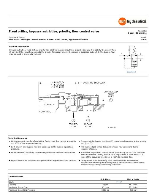
Fixed orifice, bypass/restrictive, priority, flow control valveCapacity:6 gpm (23 L/min.)Functional Group:Products : Cartridges : Flow Control : 3 Port : Fixed Orifice, Bypass/RestrictiveModel: FRCAProduct DescriptionBypass/restrictive, fixed-orifice, priority flow controls take an input flow at port 1 and use it to satisfy the priority flow at port 3. If the input flow exceeds the priority flow requirement, the excess is bypassed out port 2. The bypass flow may be used in a secondary circuit.Technical FeaturesCustomer must specify a flow rating. Factory set flow ratings are within +/- 10% of the requested setting.Pressure at the bypass port (port 2) may exceed pressure at the priority port (port 3).Both priority and bypass flow are usable up to the system operating pressure.The sharp-edged orifice design minimizes flow variations due to viscosity changes.Priority remains relatively constant regardless of variation in input flow.A tuneable adjustment control option provides up to +/- 25% variation from the nominal factory pre-set flow. Adjustment is done with +/- 3 turns of the adjust screw. Screw in (CW) to increase flow.Bypass flow is not available until priority flow requirements are satisfied.Incorporates the Sun floating style construction to minimize thepossibility of internal parts binding due to excessive installation torque and/or cavity/cartridge machining variations.DownloadFRCA-XAN$42.60Recommended List PriceControl Setting Range Seal Material Material/CoatingModifierPreferred OptionsL Tuning Adjustment +8.00 Standard OptionsK Handknob +14.00 X Not Adjustable +0.00Preferred OptionsA*Replaceable Orifice .1 -6 gpm (0,4 - 23 L/min.)+0.00Preferred OptionsN Buna-N +0.00Standard OptionsV Viton +5.00Preferred OptionsNo modifier (standard materialwith no special coating)Special Options/AP Stainless Steel, PassivatedControl: L +202.40Control: C +225.40Our corrosion resistant productline is growing! If you areinterested in a corrosionresistant option for this model,please contact Sun.Additional Options (Click Here)Control Setting Range Seal MaterialC Tamper Resistant - Factory Set +15.00B*Permanent Orifice .1 - 6 gpm (0,4 -23 L/min.)+0.00If the modifier is /AP, the control must be C or L* Special Setting required, specify at time of orderRelated Documents (opens in new window):Explanation of Sun cartridge control options - US units.Explanation of Sun cartridge control options - metric units.Copyright © 2002-2012 Sun Hydraulics Corporation. All rights reserved.Terms and Conditions - ISO Certification - Statement of Privacy。
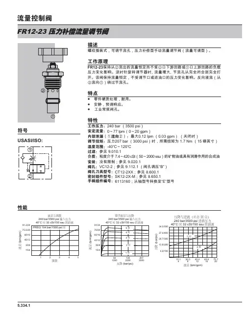
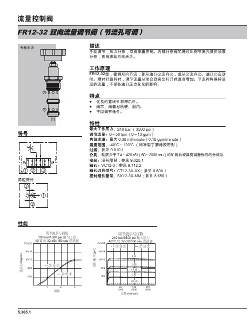
≭䛻 䬬USASI/ISO:げ㘩5.334.1流量与圈数240 bar/3500 psi 输入压力245圈数流量 (l p m /g p m )13 䔜绬先㙡遙㆞ ♾庒唑税ⷣ ☚┪嫴⌎⨚㓚┷税摞庒唑梏 税摞♾庒⨚҈ ⤲FR12-23≬虚⅝ 税茽䤓税摞㋡着力ₜ♦ ♲芚稻⥭恾㒥 ♲ₙ稻⥭恾䤓微戌☚┪♧荩砋❜ 釰㢅朗礈懻庒唑犀㢅 税摞盦⮶ 唑税ⷣ⅝眺⏷桼⚗瘸眺⏷㓢 年梏≬虚税摞㋡着 ₜ♦庒唑♲㒥扪㽈♲䤓☚┪♧荩砋❜ 莌⚠稛税 ⅝ 税⚠ 兤扖唑税ⷣ➥◥鎈ↅ䫻德⮓䚕 功䞷 眸槨 欓庒❜ㄣ ぴ₩デ屓梏ⷣ➥҈ 喝 EDU SVL ≭䛻喝 OSP JSP䘔⇰喋Ŗ≭ ŗ喌喝蜙⮶ OSP JSP ␂桼㢅䄯㞮 ⴕ喝☚┪ EDU SVL 㢅 硵榏虃誁 1P 箬喀⺇ ⍕ 㠯 喝 䓳␐喝莋屐Ϸ䉔喝伧矑⅚ℝ F6W VVX 䤓䪎䓸㽈㒥牑㦘䀵袛⇫䞷䤓⚗㒟㽈 㷱喝蠼㦘腏Ⓟ 莋屐䬬 喝9& 莋屐 梏ⷣ庒☚ % 䬬 喝&7 ;; 莋屐 ㏰Т 喝6. ; 0 莋屐㏰Т㑂 喝 ⅝戃⨚莓懻㗱綍 ( ⨚莓调节流量与压降240 bar/3500 psi 输入压力流量 (l p m /g p m )691000压降 (bar/psi)20730001382000压降与逆流(从② 到 ①)240 bar/3500 psi 进油压力压降 (b a r /p s i )4流量 (lpm/gpm)16201285.334.21.98E英寸毫米Т喝摜摞 NJ OEV 朱Ⓟ ぴ⇫槱䫻德⮓䚕 盶缂槱柏枛 蓒⺐ↅ ₐ受蟇厅 2 ⨚皽✛貆㺷鉽㖰皽 㪖瘮⨚ ➥₶䬬 喝摜摞 NJOEV 棂㨐㺶荩舊薦矑杬⚗摠 珩莓 7 欬着⋋才 EDU SVL 莋屐 㙟∪䚒犐枇材✛朱Ⓟ梏⧦ ⻉⺇♾賍ₜ⚛ 庆勣籏ぴ☑䃎䉓FR12-23 __ - __ __ __ - __ - / __ __ __ __ТN ₐ受㳰厅 㪖 V 㺮㳰厅䄯㞮䔵Т ⅔栎戃 䴉䤌 ␔⏼屡⯃ A 折ↅ$ サ婉ヌ䥥 C ⫠㠨㓚㩓 E≭䛻䃪㒚 䴉䤌 ぴ☑幍糵 JSP≭䛻䃪㒚 (gpm) 幵兕⒦㢝 5.0 JSP 10.0 JSP ䷘≭䛻䃪㒚 (lpm) 幵兕⒦㢝 M4.0 OSP M20.0 OSP ䷘䬬 ⇥ ⅔帱徼㙡孔ↅ0 6$( 10T 6$( 12T 6$(16T榏尐䔈㸙㽈♲梏⧦ 庆⚠ぴ☑✷幱。
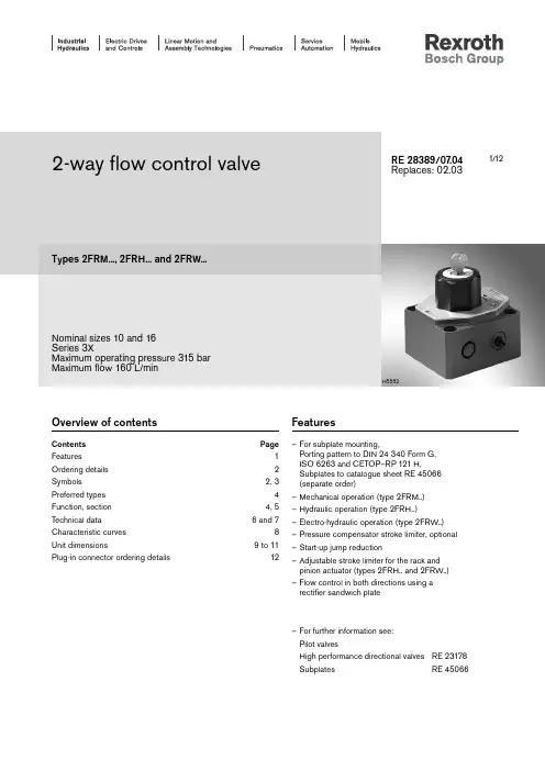
1/122-way flow control valveTypes 2FRM..., 2FRH... and 2FRW...Nominal sizes 10 and 16Series 3XMaximum operating pressure 315 bar Maximum flow 160 L/minRE 28389/07.04Replaces: 02.03Overview of contentsContents Pageeatures 1Ordering details 2Symbols 2, 3Preferred types 4Function, section 4, 5T echnical data 6 and 7Characteristic curves 8Unit dimensions9 to 11Plug-in connector ordering details12Features– For subplate mounting,Porting pattern to DIN 24 340 Form G,ISO 6263 and CETOP–RP 121 H,Subplates to catalogue sheet RE 45066(separate order)– Mechanical operation (type 2FRM..)– Hydraulic operation (type 2FRH..)– Electro-hydraulic operation (type 2FRW..)– Pressure compensator stroke limiter, optional – Start-up jump reduction– Adjustable stroke limiter for the rack andpinion actuator (types 2FRH.. and 2FRW..)– Flow control in both directions using a rectifier sandwich plate– For further information see: Pilot valvesHigh performance directional valves RE 23178 SubplatesRE 45066H5552Ordering details: 2-way flow control valveOrdering details: rectifier sandwich plateSymbol: = subplate side)Function, sectionFlow control valves of types 2FRM.., 2FRH.. and 2FRW.. are2-way flow control valves. They are used to maintain a flow constant virtually independent of pressure and temperature.The valves basically consist of the housing (1), orifice bush (2), pressure compensator (3) with optional stroke limiter (3.1), check valve (4), adjustment element (5) for type 2FRM.. as well as a rack and pinion actuator (6), directional valve (7) and actual value potentiometer (8) for types 2FRH... and 2FRW...The flow from port A to port B is throttled at the orifice (9). On type 2FRM.. the throttling area is adjusted by rotating the cur-ved pin (10) mechanically by means of the adjustment element (5), for types 2FRH.. and 2FRW.. hydraulically via a rack and pinion actuator (6), which is controlled by a built-on electrically operated directional valve (7). The control speed can be set by means of throttle check valves (6.3 and 6.4). In order to limit the required actuating range, the rack and pinion actuator (6) is fitted with adjustable stroke limiters on both ends (6.1 and 6.2). In order to to maintain the flow across the orifice (9) constant, a pressure compensator is connected upstream of the orifice (3).The flow is maintained largely independent of temperature due to the orifice design.Free return flow from port B to port A is via the check valve (4).In order to permit the orifice position in valve types 2FRH.. and 2FRW.. to be continuously monitored, an actual value potentio-meter (8) can be fitted. Suitable electrical control components are available for electrical command value pre-selection. The flow is only controlled from A to B. In order to control the flow in both directions a rectifier sandwich plate type Z4S (supply and return) can be installed under the flow control valve.Preferred types (readily available)Section X–XTypeMaterial No.2FRM 10-3X/10L R9004248872FRM 10-3X/10LB R9004232502FRM 10-3X/16L R9004232512FRM 10-3X/16LB R9004232522FRM 10-3X/25L R9004232552FRM 10-3X/25LB R9004232562FRM 10-3X/50L R9004202862FRM 10-3X/50LBR900423261TypeMaterial No.2FRM 16-3X/100L R9004249052FRM 16-3X/100LB R9004202872FRM 16-3X/160L R9004249062FRM 16-3X/160LB R9004249022FRM 16-3X/160L V R9004277772FRM 16-3X/60L R9004232712FRM 16-3X/60LBR900424903Function, sectionTechnical data (for applications outside these parameters, please consult us!)GeneralWeight NS 10NS 16Type 2FRM kg 5.611.3Type 2FRH kg9.214.9Type 2FRH..P kg10.316Type 2FRW kg11.317Type 2FRW..P kg12.418.1Rectifier sandwich plate kg 3.08.1Installation Type 2FRM InstallationTypes 2FRH and 2FRW Actuator horizontal (rack and pinion)Pressure fluid Mineral oil (HL, HLP) to DIN 51 524 1);Fast bio-degradable pressure fluids to VDMA 24 568(also see RE 90221); HETG (rape seed oil) 1);HEPG (polyglycole) 2); HEES (Synthetic ester) 2);other pressure fluids on requestAmbient temperature range NBR seals°C–30 to +80 (–30 to +50 for type 2FRW)FKM seals°C–20 to +80 (–20 to +50 for type 2FRW)Pressure fluid temperature range NBR seals°C–30 to +80FKM seals°C–20 to +80Viscosity range mm2/s10 to 800ISO code cleanliness class Maximum permissible degree of contamination of the pressurefluid is to ISO 4406 (C) class 20/18/15 3)1)Suitable for NBR and FKM seals2)O nly suitable for FKM seals3) The cleanliness class stated for the components must beadhered too in hydraulic systems. Effective filtration preventsfaults from occurring and at the same time increases thecomponent service life.For the selection of filters see catalogue sheets RE 50070,RE 50076 and RE 50081.Technical data (for applications outside these parameters, please consult us!)2-way flow control valves types 2FRM..., 2FRH... and 2FRW...NS 10NS 16 Maximum flow L/min1016255060100160 Pressure differential with free-flow from B to A,q V dependentbar2 2.5 3.56 2.8 4.37.3Minimum pressure differential bar 3 to 7 5 to 12Flow control• T emperature, stable (-20 to +80°C)± 2 % (qV max )± 2 % (qV max)• Pressure, stable (up to Dp = 315 bar)± 2 % (qV max )< ± 5 % (qV max)Maximum operating pressure, port A bar3152-way flow control valves types 2FRH... and 2FRW...Pilot volume for the max. adjustment range cm322 (300°)Pilot pressure range bar10 to 100 (max. value must not be exceeded!) Adjustment speed (dependent on the pilot pressure)Without potentiometer With potentiometer (Dependent on the pilot pressure) 5 to 2000°/s 5 to 300°/s Maximum flow (directional valve)L/min10See RE 23178 Maximum operating pressure (directional valve)bar Up to 315See RE 23178 PotentiometerActual value potentiometerResistanceΩ1000Loadability W5Maximum wiper current A0.12Protection to DIN 40 050IP 65Adjustment end position error(dependent on the adjustment speed)±1.5° at 10°/sRectifier sandwich plate Z4S...Flow, max.L/min50160 Operating pressure, max.bar315Opening pressure bar 1.5246810102030405010 L16 L25 L50 L204060802468101357902468105010015060 L100 L160 L0120401608024681013579180102030405024681012040801201602468141012Characteristic curves (measured with HLP46, ϑoil = 40 °C ± 5 °C)Scale division →Pressure differential ∆p is the same for both directions of flow q V from A to B (B to A)NS 10NS 16F l o w i n L /m i n →NS 10Free return flow (B → A)NS 10Flow control (A → B)Flow in L/min →P r e s s u r e d i f f e r e n t i a l i n b a r →F l o w i n L /m i n →P r e s s u r e d i f f e r e n t i a l i n b a r →Scale division →Flow in L/min →P r e s s u r e d i f f e r e n t i a l i n b a r →P r e s s u r e d i f f e r e n t i a l i n b a r →Flow in L/min →Flow in L/min →Characteristic curves: rectifier sandwich plate (measured with HLP46, ϑoil = 40 °C ± 5 °C)NS 16Flow control (A → B)NS 16Free return flow (B → A)1Pressure compenstor stroke limiter, optional 2Adjustment element, lockable rotary knob (may be locked in any position)Turning range 300° = 10 scale divisions M d ≈ 0.7 Nm 6Name plate 7Input "A"8Output "B"9Seal ring10.1Locating pin (NS 10 and 16)10.2Locating pin (NS 16)18Hexagon 10A/F 19Internal hexagon 3A/FNS B1B2B3B4B5B6Ø D1Ø D2D3H1H2H3H4H5L1L2L3L4T110101.582.59.56858.735.591561259526516095769.579.41316123.5101.51181.572.941.511186147117347282123.5101.511102.412Unit dimensions: 2-way flow control valve type 2FRM (in mm)Required surface finish of the mating pieceSubplates for:Nominal size 10:G 279/01 (G 1/2) G 280/01 (G 3/4)Nominal size 16:G 281/01 (G 1) G 282/01 (G 1 1/4)to catalogue sheet RE 45066 and Valve fixing screwsNominal size 10M8 x 50 DIN 912-10.9; M A = 37 Nm Nominal size 16M10 x 80 DIN 912-10.9; M A = 75 Nmmust be ordered separately.Unit dimensions: 2-way flow control valve types 2FRW, 2FRH (in mm)Nominal size 16:M10 x 160 DIN 912-10.9; M A = 75 Nm Valve fixing screws for inserting a rectifier sandwich plate between the flow controlvalve and subplate must be ordered separately.Required surface finish of the mating pieceUnit dimensions: rectifier sandwich plate Z4S... (in mm)NS B1B2B3B5Ø D1H11H12L1L2L3L410101.582.59.558.79503095769.579.416123.5101.51172.9118540123.5101.511102.4Bosch Rexroth AGIndustrial HydraulicsZum Eisengießer 197816 Lohr am Main, GermanyT elefon +49 (0) 93 52 / 18-0T elefax +49 (0) 93 52 / 18-23 58 ***************************** www.boschrexroth.de © This document, as well as the data, specifi cations and other information set forth in it, are the exclusive property of Bosch Rexroth AG. Without their consent it may not be reproduced or given to third parties.The data specifi ed above only serve to describe the product. No statements concerning a certain condition or suitability for a certain application can be derived from our information. The given information does not release the user from the obligation of own judgement and verifi cation. It must be remembered that our products are subject to a natural process of wear and aging.Ordering details: plug-in connectors to DIN EN 175 301-803 and ISO 4400 for component plug "K4"For furtherplug-inconnectorssee RE 08006Material No.Valveside Colour Without circuitry With indicator light12 … 240 VWith rectifier12 … 240 VWith indicator light andZ-diode protective circuitry24 Va Grey R901017010–––b Black R901017011–––a/b Black–R901017022R901017025R901017026。
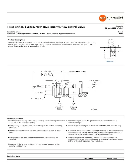
Fixed orifice, bypass/restrictive, priority, flow control valveCapacity:50 gpm (200 L/min.)Functional Group:Products : Cartridges : Flow Control : 3 Port : Fixed Orifice, Bypass/RestrictiveModel: FRFAProduct DescriptionBypass/restrictive, fixed-orifice, priority flow controls take an input flow at port 1 and use it to satisfy the priority flow at port 3. If the input flow exceeds the priority flow requirement, the excess is bypassed out port 2. The bypass flow may be used in a secondary circuit.Technical FeaturesCustomer must specify a flow rating. Factory set flow ratings are within +/- 10% of the requested setting.The sharp-edged orifice design minimizes flow variations due to viscosity changes.Both priority and bypass flow are usable up to the system operating pressure.Maximum pressure at port 3 should be limited to 3000 psi (210 bar). Priority remains relatively constant regardless of variation in input flow.A tuneable adjustment control option provides up to +/- 22% variation from the nominal factory pre-set flow. Adjustment is done with +/- 3 turns of the adjust screw. Screw in (CW) to increase flow.Bypass flow is not available until priority flow requirements are satisfied.Incorporates the Sun floating style construction to minimize thepossibility of internal parts binding due to excessive installation torque and/or cavity/cartridge machining variations.Pressure at the bypass port (port 2) may exceed pressure at the priority port (port 3).DownloadFRFA-XAN$253.80Recommended List PriceControl Setting Range Seal MaterialPreferred OptionsL Tuning Adjustment +8.00Standard OptionsK Handknob +14.00X Not Adjustable +0.00Preferred OptionsA*Replaceable Orifice .2- 50 gpm (1 - 200L/min.)+0.00Preferred OptionsN Buna-N +0.00Standard OptionsV Viton +5.00Additional Options (Click Here)Control Setting Range Seal MaterialC*Tamper Resistant - Factory Set +15.00B*Permanent Orifice .2 - 50 gpm (1 -200 L/min.)+0.00* Special Setting required, specify at time of orderRelated Documents (opens in new window):Explanation of Sun cartridge control options - US units.Explanation of Sun cartridge control options - metric units.Copyright © 2002-2013 Sun Hydraulics Corporation. All rights reserved.Terms and Conditions - ISO Certification - Statement of Privacy。
操作说明1.流速(探测)元件:压差控制器(3)处于正常开启状态并且受孔板(5)探测到的压差变化而控制。
压差上升,控制器趋向于“关”(3);压差减小,控制器趋向于“开”(3)。
这使得主阀盖压力发生变化,并使主阀在“开”或“关”之间变化以维持相对恒定的流速。
压差控制器(3)调节:沿顺时针方向旋转调节螺钉可以增大流速。
2.元件操作说明:开关元件:开关元件(4)由一个与主阀板连接的阀杆驱动。
当主阀接近全开或全关时,可以通过调节开关来驱动单刀双掷开关。
当主阀开始开启或关闭时,弹簧开关操纵杆被释放,使开关回到常规位置。
3.附件操作说明:附件A (过滤器)装置阀门进口的单向过滤器用来防止杂质微粒进入导向系统。
附件B (截断阀)阀门B1和B2用来切断主线压力向控制系统的传递。
正常操作时,这些阀门必须开启。
附件C(关阀速度控制器)CV流量控制器主要控制主阀关闭速度。
顺时针选准调节杆可以降低关阀速度。
附件G(止回阀)当出口压力大于入口压力时,止回阀(G2)开启,使出口处的高压关闭主阀,止回阀(G1)关闭,防止阀体外的液体流进入口阀。
附件Q(快速接头)快速接头便于压力仪表与主阀连接及拆卸。
附件S(开发速度控制器)CV流量控制器主要控制主阀关闭速度。
顺时针选准调节杆可以降低关阀速度。
附件T(泄压装置)泄压控制器只与止回构件(附件G)配合使用,当出口要了超过入口压力并且压差达到设定值时,泄压装置打开,使出口压力降至入口正常压力。
附件Y(Y-过滤器)Y-过滤器安装在导向器传入线上,防止杂质微粒进入控制系统。
过滤器滤网必须定期清理。
4.合理操作检查清单(1)上下游系统阀组开启。
(2)排净阀体和导向系统的所有高点气体。
(3)建议定期清理Y-过滤器。
(4)CV流量控制器至少开启4圈。
(5)止回阀B1、B2、G3、开启。
100-34 液压阀说明100-34 海托尔阀是自动控制阀的主阀,它是一个液压驱动的球形或锥形隔板控制阀。
阀体主要有三部分组成:阀体、隔板、阀盖。
Ventable, fixed orifice, bypass/restrictive, priority, flow control valve Capacity:25 gpm (95 L/min.)Functional Group:Products : Cartridges : Flow Control : 4 Port : Fixed Orifice, Bypass/Restrictive, Ventable Model: FVEAProduct DescriptionVentable, bypass/restrictive, fixed-orifice, priority flow controls take an input flow at port 1 and use it to satisfy the priority flow at port 3. If the input flow exceeds the priority flow requirement, the excess is bypassed out port 2. The bypass flow may be used in a secondary circuit. A vent port (port 4) allows these valves to be controlled remotely.Technical FeaturesCustomer must specify a flow rating. Factory set flow ratings are within +/- 10% of the requested setting. The sharp-edged orifice design minimizes flow variations due to viscosity changes.Both priority and bypass flow are usable up to the system operating pressure. A tuneable adjustment control option provides up to +/- 25% variation from the nominal factory pre-set flow. Adjustment is done with +/- 3 turns of the adjust screw. Screw in (CW) to increase flow.Priority remains relatively constant regardless of variation in input flow. Using a pressure control on port 4 will limit the pressure at the priority port (port 3). If pressure on the bypass port (port 2) exceeds the setting of the pressure control, priority flow will be shut off and all the flow will go out the bypass port.Bypass flow is not available until priority flow requirements aresatisfied, except when the valve is vented. When port 4 (vent) is open,all flow diverts to port 2 if pressure at port 1 (inlet) is 150 psi (10,5bar) or higher.Maximum pressure at port 3 should be limited to 3000 psi (210 bar).Pressure at the bypass port (port 2) may exceed pressure at the priority port (port 3). Incorporates the Sun floating style construction to minimize the possibility of internal parts binding due to excessive installation torqueand/or cavity/cartridge machining variations.DownloadFVEA-XAN$197.10Recommended List Price Control Setting Range Seal MaterialStandard OptionsK Handknob +14.00 L Tuning Adjustment +8.00 X Not Adjustable +0.00Standard OptionsA*Replaceable Orifice .2- 25 gpm (0,8 - 95L/min.)+0.00Standard OptionsN Buna-N +0.00V Viton +6.00Additional Options (Click Here)Control Setting Range Seal MaterialB*Permanent Orifice .2 - 25 gpm(0,8 - 95 L/min.)+0.00* Special Setting required, specify at time of orderRelated ModelsFVEA8Related Documents (opens in new window):Explanation of Sun cartridge control options - US units.Explanation of Sun cartridge control options - metric units.Copyright © 2002-2012 Sun Hydraulics Corporation. All rights reserved.Terms and Conditions - ISO Certification - Statement of Privacy。
流量控制阀流量控制阀是通过改变节流口通流断面的大小,以改变局部阻力,从而实现对流量的控制。
流量控制阀有节流阀、调速阀和分流集流阀等.节流阀1-阀体2—阀心3—调节螺钉4—阀套5—阀心上的螺旋断面6—阀口阀套上的窗口W与阀心上的螺旋曲线S之间的相对运动,形成了可变通流断面面积,实现了对流量的控制.改变节流口通流断面的大小,在一定的压差下,可以控制节流阀的流量。
图形符号:常见的几种节流口形式:针式节流口、三角槽式节流口、转槽式节流口流量特性:节流阀的节流口一定时,其流量随压差的增加而增大。
节流口小到一定值时流量不稳定,出现时断时续现象,称为节流口堵塞(一般0.05L/min)。
不出现堵塞的最小流量叫最小稳定流量.温度变化引起流体粘度变化使流量不稳定(可采用温度补偿装置加以补偿)。
调速阀调速阀是具有恒流量功能的阀类,利用它能使执行元件匀速运动.1—减压阀部分 2-减压口 3—行程限位装置 4—节流阀部分 5-节流口调速阀由两部分组成,一是节流阀部分,二是定差减压阀部分,两部分串联而成。
图形符号:工作原理:将节流阀前后压力p2和p3分别引到定压减压阀阀心下、上两端.当负载压力p3增大即调速阀压差变小时,作用在定差减压阀心的力使阀心下移.减压口增大,压降减少,使p2也增大,从而使节流阀压差△p=p2-p3保持不变;反之亦然,这样就使调速阀的流量不受其压差变化的影响,而保持恒定。
详细原理说明原理说明:通过阀的流量,不随阀前后的压差ΔP(ΔP = P1—P3)而变,而节流阀就无恒流功能。
比较下列曲线可见两者的区别。
调速阀可理解为两个串联节流口组成,Ⅰ为固定节流,Ⅱ为可变节流口。
执行元件工作时,流量Q稳定流过。
外负载F若减小,两个串联节流口的流量Q将会增大。
这时如果能够及时且自动地减小节流口Ⅱ的开度,使流量重回到原来的稳定值Q。
要做到这些就必需自动地保持(P2-P3)不变.Ⅰ节流口用节流阀,Ⅱ节流口用定差减压阀,它可保证节流阀前后压差(P2—P3)不变,因此可实现恒流。
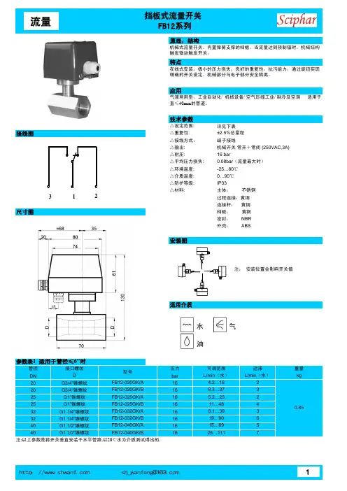
≭䛻 䬬
䔜
绬先㙡遙㆞ ⦉着唑税ⷣ ☚┪嫴⌎⨚税摞庒唑梏 唑税⨚
҈ ⤲
FR12-20F ≬虚⅝ 税茽䤓税摞㋡着力ₜ♦ ♲芚稻⥭恾䤓微戌☚┪♧荩砋❜ ⦉着虱Ⓟ唑税ⷣ茽☑㢅碏睃㓆税摞屓㫋欓糵 ㇢抩扖梏䤓稛税⦷虱Ⓟ唑税ⷣℶ䞮䤓☚┪蕠怔扖 EDU SVLG 㢅 梏眑❜ㄣ微戌♧荩 ⦷ EDU SVL 䤓☚┪喒⦃茫 ♾冃虚位誑䤓税摞 莌⚠稛税 ⅝ 税⚠ 抩扖虱Ⓟ唑税ⷣ 蠼㦘嫴⌎
➥◥
鎈ↅ䫻德⮓䚕 功䞷 眸槨 欓庒❜ㄣ
ぴ₩デ屓梏ⷣ
➥
҈ 喝 EDU SVL
䷉ ≭䛻喝 OSP JSP 蜙⺞ OSP JSP 蜙⮶⍕ 㠯 喝 䓳␐喝莋屐
Ϸ䉔喝伧矑⅚ℝ F6W VVX 䤓䪎䓸㽈㒥牑㦘䀵袛⇫䞷䤓⚗㒟㽈 㷱喝蠼㦘腏Ⓟ 莋屐 䬬 喝9& 莋屐
䬬 喝&7 ;; 莋屐 ㏰Т 喝6. ; 0 莋屐
USASI:
ISO:
げ
㘩
5.302.1
18.8/5
(l p m /g p m )
40°C 32 cSt/150 ssu
971400 (bar/psi)
14521002413500
56.8/15
37.9/10
48700193
2800
FR12-20F - __ __ __ - __ - / __ __ __ __
Т喝摜摞 NJ OEV 朱
Ⓟ ぴ⇫槱䫻德⮓䚕 盶缂槱柏枛 蓒⺐ↅ ₐ受蟇厅 2 ⨚皽✛貆㺷鉽㖰皽 㪖瘮⨚ 䬬 喝摜摞 NJ OEV
棂㨐㺶荩舊薦矑杬⚗摠 珩莓 7 欬着⋋才 EDU SVL 莋屐 㙟∪䚒犐枇材✛朱Ⓟ梏⧦ ⻉⺇♾賍ₜ⚛ 庆勣籏ぴ☑
䃎䉓
䬬 ⇥ ⅔帱徼㙡孔ↅ 0 6$( 10T 6$( 12T 6$( 16T
5.302.2
≭䛻䃪㒚 (lpm) √Ⱁ M4.0 OSP M12.0 OSP ䷘ ≭䛻䃪㒚 (gpm) √Ⱁ 5.0 JSP 13.0 JSP
䷘ 䧧 ∁
ⅴ⺇䤓◒⒕⃚帰並 √Ⱁ
D030 㘶Ⓟ唑㿐ⷣ 喀⺇
䷘
节流孔片不能用于此产品。
1.981.2531.8
对边宽度安装扭矩:30 ft-lbs
(40.6Nm )英寸
毫米
Т ₐ受㳰厅 㪖 N 㺮㳰厅 V
∔喝㦏⺞杊ⷣ䦃㈓㢾 喀⺇ 㦘␂㦃⺞䤓唑
㿐ⷣ⮶⺞ 庆⚠ぴ☑✷幱。