压链机--英文使用说明-更改打印设置后的效果
- 格式:pdf
- 大小:269.43 KB
- 文档页数:12

原版操作手册的译本CANopen ®, EtherNet/IP ®, MODBUS ®, PI PROFIBUS PROFINET ® 是商标持有人在相关国家注册的商标。
.1关于本文件Tab. 1 伺服压机适用文件其它文件名称,型号目录在线帮助 YJKP 伺服压力机套件 YJKP 的软件操作应用注意事项关于连接和调试的应用范例è /spTab. 2 伺服压机的其它文件在单独的文件中说明压机各组件的应用范围及认证è /sp 。
2安全2.1按规定使用本产品是用于执行接合任务的组件,带监控接合过程的功能。
组件可在带上级控制器的机器或自动技术设备内部使用。
只能在下列条件下使用本产品:–在技术性能完好的状态下–在原版状态下使用,不得擅自改动–在本产品技术数据定义的极限值内使用–在工业领域内–牢固安装2.2可预见的错误使用禁止在下列条件下使用本产品:–擅自对产品进行更改或改装–超出负载极限值–安装位置不符合要求2.3专业人员的资质仅允许由具备资质的专业人员安装、调试、保养和拆卸本产品。
专业人员必须掌握机电一体化系统安装的专业知识。
3详细信息–附件 è /catalogue 。
–备件 è /spareparts 。
4服务若有技术问题,请联系 Festo 公司在您所在地的联系人 è 。
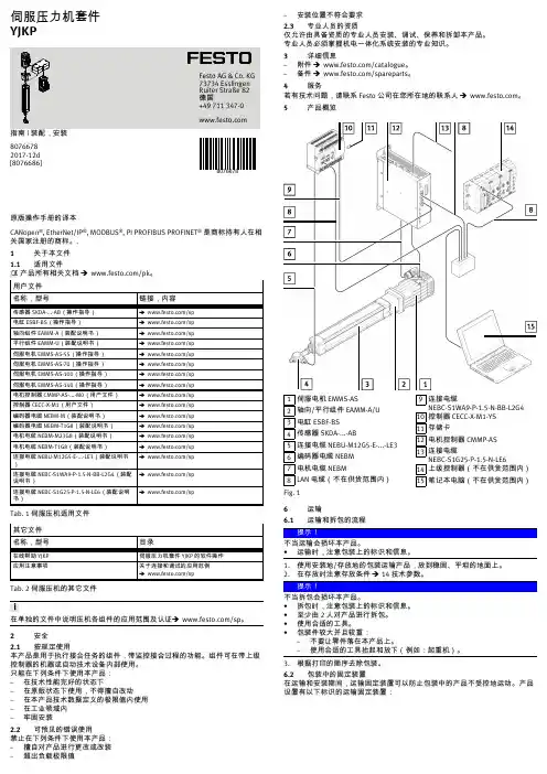
5产品概览1伺服电机 EMMS-AS2轴向/平行组件 EAMM-A/U 3电缸 ESBF-BS4传感器 SKDA-...-AB5连接电缆 NEBU-M12G5-E-...-LE3 6编码器电缆 NEBM7电机电缆 NEBM8LAN 电缆(不在供货范围内)9连接电缆NEBC-S1WA9-P-1.5-N-BB-L2G4 10控制器 CECC-X-M1-YS 11存储卡12电机控制器 CMMP-AS13连接电缆NEBC-S1G25-P-1.5-N-LE614上级控制器(不在供货范围内)15笔记本电脑(不在供货范围内)Fig. 1 6运输6.1运输和拆包的流程不当运输会损坏本产品。

LineGene9600Plus使⽤说明书体外诊断(IVD)医⽤设备Fluorescent Quantitative PCRDetection system荧光定量聚合酶链反应(PCR)检测系统LineGene 9600系列Operation Manual使⽤说明书注意?建议⽤户使⽤Bioer 荧光定量聚合酶链反应(PCR)检测系统之前,仔细阅读该使⽤说明书。
特别留意该说明书中所述的警告及注意事项。
请将说明书妥善保管,以在需要的时候可以及时⽤于参阅。
Attention ?Users are recommended to carefully read the contents of this manual before operating the Bioer Fluorescent Quantitative PCR Detection System.To Carefully observe all special Warnings and Cautions outlined in this manual.This manual should be maintained properly in good condition for reference.注意:版权所有,本⽂件中所包含的信息若有修改,恕不另⾏通知。
本⽂有受版权保护的专利资料,版权所有,未经杭州博⽇科技有限公司事先书⾯同意,不允许对本⽂件中的任何部分进⾏复印、重新制作或翻译成其它语⾔。
衷⼼感谢您选购本产品⾸次使⽤本仪器时,请务必先仔细阅读使⽤说明书!产品标准号: YZB/国0432-2015产品注册号:国械注准20153400273医疗器械⽣产企业许可证:浙⾷药监械⽣产许20150033号⽂件编号:BYQ609400000000SM⽂件版本:2015年4⽉第1.1版重要说明1惯例声明:注意项⽬中包含特别重要的信息,请您仔细阅读。
如果不按照说明书中的要求操作,将有可能造成仪器损坏或⽆法正常⼯作。

专业音响效果处理器YAMAHA SPX990 的使用与操作YAMAHA SPX990专业综合效果处理器是继YAMAHA 公司在SPX900、SPX100之后推出的,尽管推出至今已有四五年光景,同时也在众多的专业音响系统(包括一些剧场、夜总会、歌舞厅)中使用,该效果器共提供了280种效果程序,其中预置程序为1-80个,用户使用程序为1-99个,00是第100个程序,扩展记忆程序为-99,00是第100个程序,此处还包括了对混响和前期反射声的真实模拟,延迟和回声效果,调制效果,处理声效果,复合效果,门混响,音调效果,以及可循环的采样程序等。
SPX990在功能上比SPX900又上了一个档次,采用了20bitA/D和D/A转换器,增加了多种前后级效果,以及带有记忆的扩展卡槽,简捷的功能键,数据轮等,虽简化了操作步骤,但由于液晶显示屏所显示的数据有林林种种,又全都是英文缩写,使不少操作者感到使用起来极为不便,难以正确调整其中的各种参数,为此下面就具体介绍它的功能与操作,供使用者参考:一、控制与连接1、电源开关按此键可打开/关闭SPX990电源,当电源打开后,显示屏将调出上次关机时的程序和参数。
2、输入电平控制内/外部旋钮分别控制左/右声道的模拟信号输入电平。
3、输入电平表立体声输入电平表将左右声道分成八段,分别对应-42,-36,-30,-24,-18,-12,-6和削波灯指示。
4、记忆指示显示选择记忆的类型:预置,用户或记忆卡。
5、输入选择指示显示输入状态:立体声或单声道。
6、MIDI指示当接收到MIDI信号时,此显示器将被点亮。
7、程序号显示显示当前的程序号,在选择过程中程序号将闪亮,调出或存储后将常亮。
8、LCD液晶显示器液晶显示器将显示程序名,参数等信息。
9、功能键(上/下)用来直接调出或按照普通方法调出效果程序,还可用来存储操作,编辑液晶屏上选择的参数值。
10、数据调节轮用来调节程序号或参数值。

Operating instructions Page 12 Wine storage cabinet12Description of the applianceSaving energy- Always ensure good ventilation. Do not cover ventilation open-ings or grille.- Always keep fan slits clear.- Avoid positioning the appliance in direct sunlight or near cookers, radiators and similar sources of heat.- The energy consumption depends on the installation conditions, e.g. the ambient temperature.- Keep the time the appliance is open to a minimum.Accumulated dust increases the energy consumption:- Once a year, dust the refrigeration unit together with the metal grid of the heat exchanger at the back of the appliance.Disposal notes The appliance contains reusable materials and shouldbe disposed of properly - not simply with unsorted household refuse. Appliances which are no longer needed must be disposed of in a professional and appropriate way, in accordance with the current local regulations and laws.When disposing of the appliance, ensure that the refrigerant circuit is not damaged to prevent uncontrolled escape of the refrigerant it contains (data on type plate) and oil.• Disable the appliance.• Pull out the mains plug.WARNINGDo not allow children to play with packaging material. Take the packaging material to an official collection point.Climate ratingeration performance.type plate.The position of the type plate is shown inthe section entitled Description of the appliance .Climate rating Room temperature SN +10°C to +32°C N +16°C to +32°C ST +16°C to +38°C T+16°C to +43°C SN-ST +10°C to +38°C SN-T+10°C to +43°CDo not operate the appliance outside the specified room temperature range.EPREL databaseAs from 1 March 2021, information about energy labelling and ecodesign requirements will be available in the European product database (EPREL). You can access the product database using the following link: https://eprel.ec.europa.eu/. You will be asked to enter the model identifier. You will find the model identifier on the type plate.EN Safety instructions and warnings• T o prevent injury or damage to the unit, the ap-pliance should be unpacked and set up by twopeople.• In the event that the appliance is damaged ondelivery, contact the supplier immediately beforeconnecting to the mains.• T o guarantee safe operation, ensure that the ap-pliance is set up and connected as described inthese operating instructions.• Disconnect the appliance from the mains if anyfault occurs. Pull out the plug, switch off or removethe fuse.• When disconnecting the appliance, pull on theplug, not on the cable.• Any repairs and work on the appliance shouldonly be carried out by the customer servicedepartment, as unauthorised work could provehighly dangerous for the user. The same applies to changing the mains power cable.• Do not allow naked flames or ignition sources to enter the appliance. When transporting and cleaning the appliance, ensure that the refrigerant circuit is not damaged. In the event of damage, make sure that there are no ignition sources nearby and keep the room well ventilated.• Do not stand on the plinth, drawers or doors or use them to support anything else.• This appliance is not intended for use by persons (including children) with reduced physical, sen-sory or mental capabilities or lack of experience and knowledge unless they have been given initial supervision or instruction concerning use of the appliance by a person responsible for their safety. Children should be supervised to ensure that they do not play with the appliance.• Avoid prolonged skin contact with cold surfaces or chilled/frozen food. T his could cause pain, numb-ness and frostbite. In the case of prolonged skin contact, protective measures should be taken, e.g. gloves should be worn.• Do not consume food which has been stored for too long, as it could cause food poisoning.Range of appliance useThe appliance is suitable solely for storing wine in a domestic environment or similar. This includes, for example, use- in staff kitchenettes, bed and breakfast establish-ments,- by guests in cottages, hotels, motels and other forms of accommodation,- in catering and similar services in the wholesale trade.Use the appliance solely as is customary within a domestic envi-ronment. All other types of use are inadmissible. The appliance is not suitable for storing and cooling medicines, blood plasma, laboratory preparations or similar substances and products cov-ered by the 2007/47/EC Medical Devices Directive. Any misuse of the appliance may result in damage to or spoilage of stored goods. Furthermore, the appliance is not suitable for operation in potentially explosive atmospheres.• Do not store explosives or sprays using com-bustible propellants such as butane, propane, pentane, etc. in the appliance. Electrical com-ponents might cause leaking gas to ignite. Y ou may identify such sprays by the printed contents or a flame symbol.• Do not use electrical appliances inside the ap-pliance.• If you have a lockable appliance, do not keep the key near the appliance or within reach of children. • The appliance is designed for use in enclosed areas. Do not operate the appliance outdoors or in areas where it is exposed to splash water or damp conditions.• The fluorescent tube illuminates the interior of the appliance. It is not suitable for lighting a room.1314Appliance dimensionsWKb 1812 A = 890 mmB = 613 mmC= 1172 mmSetting up • Avoid positioning the appliance in direct sunlight or near cookers, radiators and similar sources of heat.• • • the wall.Electrical connectionOnly operate the appliance with alternating current (AC)..• If several appliances are installed next to each other, leave a gap of 50 mm between them.If this gap is too narrow, condensation forms between the side walls.• T a top unit can be added.A gap of at least 50 mm depth must be provided behind and along the entire width of this unit so as to ensure sufficient ventilation. The area of ventilation underneath the ceiling should be at least 300 cm 2.15ENSetting the temperatureIncreasing the temperature Press the Up button.Reducing the temperature Press the Down button.will start to flash.- setting. - actual temperature will be displayed.Operating and control elements1T emperature display2T emperature setting buttons 3Audible warning On/Off button 4Child lock activated symbol 5On/Off button6Fan On/Off button combination 7Fan On symbol8Interior light on/off buttonSwitching the appliance on and offSwitching the appliance onPress the On/Off button until the temperature display lights up.Switching the appliance offKeep the On/Offthe temperature display goes out.Storing wineIf you are storing wine for long periods of time, it should be stored at a temperature of between 10°C and 14°C.This is the temperature wine cellars are kept at, and it is just right to allow wine to mature properly.The following drinking temperatures are recommended for the various types of wine.Red wines: +14°C to +18°C Rosé wines: +10°C to +12°C White wines: +8°C to +12°CSparkling wines, Prosecco: +7°C to +9°C Champagne: +5°C to +7°CFan switchThe interior fan guarantees that the interior temperature remains constant and uniform and also increases the humidity in the appliance.In addition to reducing the humidity level, switching off the fan will result in lower energy consumption (energy saving mode).Increased humidity will prevent the corks drying out over a lengthy period.Switching onHold down the Alarm button and then press the Light button. The LED will come on.Switching offHold down the Alarm button and then press the Light button. The LED goes dark.NoteIf the appliance is operated in a low ambient temperature, the fan may also run when the fan function is deactivated.16Door open alarmIf the door is left open for more than 60 seconds, the audible warning signal will sound.If the door must be opened for a lengthy period to place items into the appliance, cancel the audible warning signal by pressing the Alarm button.The alarm switches back to standby when the door is shut.Temperature alarmIf the temperatures in the interior are out of the per-mitted range, the audible warning signal will sound and the temperature display will flash.After a lengthy power failure, the temperature in the interior may have risen to too high a level. After the power supply returns, the fall in temperature can be watched on the display.• Cancel the audible warning signal by pressing the Alarm button. The temperature display will stop flashing as soon as the tem -perature in the interior has reached the set value.Temperature alarm after a fault in the applianceIf the appliance develops a fault, the temperature in the interior may rise too high or fall too low. The audible warning signal will sound and the temperature display will flash.If the temperature displayed is too high (warm), first check whether the door is closed correctly.If the temperature display continues to show a value that is too high or too low after one hour, contact the customer service department.• Cancel the audible warning signal by pressing the Alarm button.If F1 appears in the display, the appliance has suffered a fault. Inthis case, contact the customer service department.Interior lightis opened.Press the Light1pose.2left.3downwards.4Tdownwards.17LabelsThe appliance is supplied with a label holder with labels for each shelf. Use these to label the type of wine stored on each shelf.Additional labels can be obtained from your dealer.Version 1Click the label holder into place and slide the label in from the top.Version 2Click the label holder into place and slide the label in from theside.Air exchange with activated charcoal filterfor preserving the wine.We r ecommend t hat y ou ryour dealer.Changing the filterTake the filter by theand remove.Inserting the filter Storage diagrams for 750 ml Bordeaux bottles1819ENCleaningBefore cleaning always switch off the appliance. Pull out the mains plug or switch off or unscrew the fuse.• Clean the inside and outer walls with lukewarm water and a lit-tle detergent. Do not use abrasive or acid cleaners or chemical solvents.• Use a glass cleaner to clean the glass surfaces and a commercially available stainless-steel cleaning agent for the stainless-steel surfaces.Do not use steam cleaners because of therisk of injury and damage.• Ensure that no cleaning water penetrates into the elec t rical components or ventilation grille.• Do not damage or remove the type plate on the inside of the appliance. It is very important for servicing purposes.DefrostingThe appliance defrosts automatically.Shutting your appliance downIf your appliance is to be shut down for any length of time, switch it off and disconnect the plug or switch off or unscrew the fuse. Clean the appliance and leave the door open in order to prevent unpleasant smells.The appliance complies with the relevant safety regulations and EU Directives 2014/30/EU and 2014/35/EU.Malfunctions• F1 appears in the display.– The appliance has suffered a fault. Contact the customer service department.You may be able to rectify the following faults by checking the possible causes yourself.• Appliance does not function:– Is the appliance switched on?– Is the plug correctly fitted in the mains socket?– Is the fuse intact?• When inserting the mains plug, the refrigeration unit does not switch on, but a value is shown in the temperature display.– Demo mode is activated. Deactivate demo mode as described in the section entitled Additional functions - Demo mode .• Loud running noise:– Is the appliance set up firmly on the floor?– Does the appliance cause nearby items of furniture or objects to vibrate? Please note that noises caused by the refrigerant circuit cannot be avoided.• The temperature is not low enough:– Is the temperature setting correct (see "Setting the temperature")?– D oes the separately installed thermometer show the correct reading?– I s the ventilation system working properly?– I s the appliance set up too close to a heat source?ignation 12Changing over door hingesDoor hinges should only be changed by a trained expert.1.hinge bracket.2.upwards.Important3.fingertip.4.downwards.5.T ransfer plug.6.9.2021EN14. to the lower hinge bracket.Importantmodels W Kb 3212 and W held secure by one person.15. the hinge bracket.the hinge bracket.16.Adjusting the lateral tilt of the door If the door is at an angle, adjust the angle. This screw is no longer needed.18.Liebherr Hausgeräte Lienz GmbHDr.-Hans-Liebherr-Strasse 1A-9900 LienzÖsterreich*708323400*。

ALMCB使用说明书件号:OM5339Z135杭州优迈科技有限公司2013年03月1.1产品名称ALMCB板是控制系统的核心部分,按照模块化设计,包含了OCSS(操作控制)、MCSS(运行控制)、DBSS(驱动控制)和DCSS(门系统控制)。
电梯系统结构图ALMCB板1.3产品结构ALMCB 电路分布示意图ALMCB板电路分为:模拟电路和数字电路,模拟电路包括:电源电路,通信电路,输入输出电路,服务器接口电路,编码器电路,模拟量检测电路;数字电路包括:CPU电路,CPLD电路以及其它外围电路;ALMCB板示意图ALMCB外围接线示意图外围接线示意图ALMCB板按钮、拨码开关、指示灯和端口说明ALMCB板按钮说明代号功能说明备注K1顶层指令TOPK2底层指令BOT 板拨码开关说明代号功能说明备注SW4(K7)开关门操作使能/禁止DDOSW3(K7)厅外召唤操作使能/禁止CHCSALMCB板指示灯说明ALMCB板端口说DC24V信号输入端子(P1)8PIN WAGO 721-138/001-000型插座,对应的插头为721-108/026-000DC24V信号输入端子(P2)AC110V信号输入端子(P3)AC110V信号输出端子(P4):DC24V信号输出端子(P5)轿内、厅外信号通讯端口(P6)4P IN WAGO 721-电源输入端子(P7)群控信号通讯端口(P8):4PIN WAGOEFK信号反馈端口(P9)3PIN提前开门/再平层功能端口(P10)2PIN WAGO编码器信号输入端子(X3): PVT口1.4串行通信ALMCB板采用RSL通讯,为了抵抗电磁干扰,所以在通信线的终端加入阻抗匹配是必须的;ALMCB板通信线最大长度150m,终端吸收板阻抗匹配值为:75Ω/;示意图如下:适用范围ALMCB需要和我司的CON8003/CON8005/CON8006/ CON8007驱动器一起配套使用;电梯厅外和轿内的召唤和楼层显示采用的是RSL串行通讯。
第一台自动印刷机软件说明书File:2005 1003-1 Software Menu.doc Ver 1.011-08-20051.文件1.1. 文件的打开该窗口可以载入工作文件。
在此窗口中用户可以选择工作文件,其中包含印刷参数、循环选项和观察系统的配置。
在弹出窗口中完成选择后,按Open按钮来载入文件或按Cancel按钮来退出窗口。
1.2. 文件的保存这条命令用来在Data Prog(最近一次载入的程序)文件中保存机器当前的参数。
1.3. 文件的另存为该窗口能可以保存当前工作文件。
在这个窗口用户可以选择工作文件或键入一个新的文件名,并可以保存印刷参数、循环选项和观察系统的配置。
在弹出窗口中完成选择后,按Save按钮或按Cancel按钮来退出窗口。
1.4. 退出通过这条命令用户可以关闭此程序从而回到windows NT的桌面。
使用这个选项需要高级密码。
2.机器2.1. 循环循环窗口所包含的所有参数并不与网板精确定位有关,而是偏重于机器的参数,例如“Enable printing”,“Enable magazine loader”,“Enable oven heating”等等。
具体来说,从窗口第一行开始,还列出以下选项:1.Enable Magazine Loader:不选择此选项,机器运作时不会从装载盒中装载电池。
2.Enable Printing(需要密码):不选择此选项,印刷步骤会被跳过,因此电池会装载上工作台,排列成一行(如果选项“Alignment”在51页被选中的话),然后未被印刷就卸载了。
3.Enable Flip-Over:不选择此选项,翻转器失效并且电池在第二台印刷机加工之前没有被翻转。
4.Enable Load Breakage Wafer:不选择此选项,翻转器在工作台定位器之上不会检测晶片是否破碎。
5.Enable Oven Heating(需要密码):这个选项控制烘箱加热器是否工作。
目录一、概述 (1)二、工作原理 (1)三、主要技术参数 (3)四、设备安装及连接 (3)五、现场调试步骤 (4)六、操作规程 (6)七、维护和维修 (7)八、注意事项 (8)九、附录附录一液压拉紧装置推荐用液压油附录二电气外围信号接线图附录三电控系统原理图附录四电控系统面板布置图此为四川向家坝电厂液压自控拉紧装置说明书部分电源线号注有所不同请对照电器图工作原理一致第1 页一、概述带式输送机液压自动拉紧装置是根据我国散料运输特点,吸取世界工业发达国家的先进技术,考虑输送带在起动和正常运行时所需拉紧力不同,确定合理的张力模型而设计的。
本拉紧装置的特点是:(1)改善带式输送机运行时胶带的动态受力效果,特别是胶带受到突变载荷时尤其明显;(2)起动和正常运行的不同拉紧力,可以根据带式输送机的实际需要任意调节(其调节范围由所选拉紧装置的型号规格确定)。
系统一旦调定后,即按预定的程序自动工作,使输送机处在理想的工作状态下运行,大大改善输送带的受力状况。
(3)响应快。
由于输送机起动时,输送带松边会突然松弛伸长,引起“打带”、冲击现象。
此时,拉紧装置能迅速收缩油缸,及时吸收输送带的伸长,从而大大缓和了输送带的冲击,使起动过程平稳,避免发生断带事故。
(4)具有断带时自动停止输送机的保护功能。
(5)结构紧凑,安装空间小,便于使用。
ZLY型液压自动拉紧装置适用于长距离带式输送机的张紧,主要由拉紧油缸、液压泵站、蓄能站、地面PLC型控制开关和拉紧附件等五大部分组成。
其中液压泵站、蓄能站和地面PLC型控制开关不需要做地基,仅要求安放地点不落物料和水即可。
二、工作原理图1为ZLY的液压系统原理图及油缸与拉紧小车缠绕示意图。
为满足带式输送机对拉紧力起动时大,正常运行时小的要求,液压系统可相应地提供高(由溢流阀3控制)和比例阀13两种油压。
为此,首先需将各溢流阀和压力继电器的整定值从大到小依次为溢流阀9、溢流阀3、电接点压力表上、下限、压力继电器。

用户手册目录1 • 简介与安全警告 (1)一般信息与免责声明 (1)安全 (3)2 • 支持 (4)技术支持与维修 (4)应用工程服务 (5)应用工程服务 (5)3 • 设置与入门 (6)打印机组件概述 (7)连接打印机 (8)4 • 触摸屏 - 基本信息 (10)主页屏幕信息 (10)主页屏幕上的活动菜单图标 (10)主页屏幕顶部的信息图标 (11)主页屏幕上的 IP 打印耗材信息 (11)基本菜单导航 (12)5 • 打印模式 (14)智能打印系统 (14)Brady 模式打印(IP 打印) (14)标准模式打印 (14)部分 Brady 模式/部分标准模式 (15)有关 IP 打印组件的其他信息 (16)6 • 加载耗材 (17)加载顺序 (17)取出已安装的耗材 (17)加载标签卷 (18)加载层迭标签介质 (20)加载色带卷 (21)选择和设置标签传感器 (23)7 • 打印 (26)校准(打印介质馈送的同步) (26)撕纸模式打印 (26)自动切割打印 (26)8 • 清洁与维护 (28)认可的清洁棉签 (28)清洁打印辊 (28)清洁打印头 (28)清洁标签传感器 (29)清洁切刀(自动切刀型号) (29)9 • 故障排除 (30)错误屏幕导航 (30)带有补救方法的错误消息列表 (30)10 • 介质尺寸规格 (36)标签/打印介质尺寸 (36)打印机和传感器尺寸 (37)反射标记尺寸(“黑色标记”) (38)槽口/切口尺寸 (39)11 • 许可证与机构许可 (40)1 • 简介与安全警告一般信息与免责声明以下产品的用户手册:免责声明本手册是 Brady Worldwide, Inc.(后文称为 “Brady”)的专有财产,可能会不时进行修改,恕不另行通知。
Brady 不承担为您提供此类修 改(如果有)的责任。
我们保留本手册的所有版权。
若无 Brady 的事先书面同意,不得使用任何方式拷贝或复制本手册的任何部分。

拉链压胶机操作方法
以下是拉链压胶机的操作方法:
1. 准备好需要压胶的拉链和压合机具,确保机器处于关闭状态。
2. 将拉链放在机器的适当位置,通常是两个压合装置之间的夹持区域。
3. 打开机器,并根据机器的说明书设置合适的压力和温度。
通常,合适的温度会使胶水快速变稠并形成牢固的粘合。
4. 将胶水均匀地涂在拉链的两侧,确保涂覆的面积足够大以确保牢固的粘合。
5. 将拉链放入机器的夹持区域,并确保拉链完全对齐。
6. 关闭压合装置,并确保拉链可以在夹持区域中自由移动。
不要用力压紧夹持装置,否则可能会损坏拉链。
7. 等待一段时间,以使胶水在合适的温度和压力下干燥和粘合。
时间的长度取决于机器的设置和胶水的类型。
8. 打开机器的压合装置,并小心地取出已经粘合的拉链。
9. 检查拉链的粘合情况。
如果拉链没有完全粘合,可以再次将其放入夹持区域进行后续操作。
10. 重复以上步骤,直至所有拉链都被成功粘合。
请注意,这只是一般的操作方法,实际的操作方法可能会因机器型号和胶水类型的不同而有所不同。
在操作之前,请仔细阅读所使用机器的说明书,并遵循其操作指南。
用户手册LQ-200KII系列票据打印机安全指引请在使用本产品前仔细阅读本手册,不要执行本手册中没有明确说明的操作。
未经授权的操作会导致错误或意外。
制造商对因错误操作而导致打印机出现的任何问题均不负责。
请严格遵守标示在打印机上的所有警告和指导。
如果您刚使用过打印机,打印头可能很热,请勿触碰打印头。
安装连续纸的时候不要把手指放在拖纸器链齿盖的下面。
请勿带电或用酒精等化学用品清洁打印机。
如需清洁,请先把电源插头拔下,用微湿的柔软布料擦拭。
请勿在容易被液体溅到的地方使用打印机。
请勿堵塞机壳上的小槽或开孔。
不要把打印机放在睡床、沙发、地毯或其它类似物品的表面,以防堵塞通风孔。
如果打印机被置于比较拥挤的环境中工作,应采取相应的通风措施。
打开包装之前,应考虑好放置打印机的位置。
应选择一个平稳的台面或坚固的打印机台架,并要确保打印机周围有足够的空间,以便纸张容易进出。
避免与其他大功率电器或容易引起电压波动的电器设备使用同一交流电源插座。
将整个计算机系统远离可能引起电磁干扰的器件,例如扬声器或无线电元件。
请勿把电源线放在容易被踩到的地方。
如果电源线或电源插头已破损或断裂,请马上停止使用并更换新部件。
避免把打印机放在温度和湿度变化较大的地方,如:阳光直射、靠近热源、多尘或多油烟的地方。
为防止触电或引起短路,请勿把任何物体从打印机通风孔推入机体内。
请勿自行检修打印机,或打开打印机的外壳,以免触电或产生其它危险。
如需检修应找专业维修人员。
在不用打印机时,应关闭打印机电源并拔掉电源线。
外接插座应安装在接近打印机的地方。
出现以下情况时,请拔掉打印机电源线,并与专业维修人员联系:A:当电缆或插头损坏、磨损时。
B:当有液体溅入机内时。
C:当打印机被雨淋湿或进水时。
D:当遵从操作手册操作,机器却不能正常工作时。
E:当机器被摔落,造成机壳损坏时。
F:当打印机特性明显变坏,需要维修时。
注:本手册内容如有更改,恕不另行通知* 本产品所有部件均为可回收设计,当用户需要废弃本产品时,本公司负责无偿回收,具体处理方法请联系本公司售后服务部。
感谢您购买压书机 (BP1)。
请阅读并遵循本用户指南中的说明,获得压书机 (BP1) 的最佳效果。
您需要的物品:
115 – 120 psi 的无水可持续压缩空气源
这将提供大约 8.5 吨的压力
适合支撑装置的稳定表面
装置重量约为 280 磅
压书机 (BP1) 装置
使用压书机 (BP1) 对书芯施加压力:
1.将压书机 (BP1) 装置放在适合操作员合适高度的稳定表面上。
2.将装置连接到压缩空气源。
3.将装钉后的书芯放入压书机的压台之间。
4.用双手按压压书机各侧的按钮以便咬合。
5.咬合压书机(保持)30 秒。
6.30 秒之后,松开按钮。
7.现在,书芯即可进行 3 面修剪。
8.根据所需要的成品书大小进行修剪。
9.现在,书芯即可套入并应用封面。
使用压书机 (BP1) 应用最后的压力密封:
完成封面卷纸器 (CC1) 步骤后,使用压书机 (BP1) 完成构制书籍的最后阶段。
1.将书籍(连同封面)放入压书机的压台之间,然后施加压力 30 秒钟。
2.书籍现在便可交付客户!
重要说明:我们鼓励每个客户构制测试书,让您对产生的效果感到舒心和满意,然后再继续
进行实际的生产运作。
有关压书机 (BP1) 操作的更多信息,请访问
CS 183 修订日期:2010 年 11 月 10 日
Chinese Simplified。
Register this product at 99925150 REV 2© 2011 Greenlee Textron Inc.9/111981Mechanical Crimping Tool1981 Mechanical Crimping ToolGreenlee / A Textron Company4455 Boeing Dr. • Rockford, IL 61109-2988 USA • 815-397-70702All specifications are nominal and may change as designimprovements occur. Greenlee Textron shall not be liable for damages resulting from misapplication or misuse of its products.Blackburn is a registered trademark of Thomas & Betts.KEEP THIS MANUALImportant Safety InformationDescriptionThe 1981 Mechanical Crimping Tool is intended for crimping copper color-coded lugs and splices from 8 AWG through 250 kcmil and aluminum color-coded lugs and splices from 6 AWG through 4/0 AWG.SafetySafety is essential in the use and maintenance ofGreenlee tools and equipment. This instruction manual and any markings on the tool provide information for avoiding hazards and unsafe practices related to the use of this tool. Observe all of the safety information provided.Purpose of this ManualThis manual is intended to familiarize all personnel with the safe operation and maintenance procedures for the following Greenlee tool: 1981 Mechanical Crimping Tool Keep this manual available to all personnel.Replacement manuals are available upon request at no charge at .1981 Mechanical Crimping ToolGreenlee / A Textron Company4455 Boeing Dr. • Rockford, IL 61109-2988 USA • 815-397-70703Operation1. Refer to the connector manufacturer’s instructionsfor preparing the cable and connector.2. Set the nest (adjustable die) of the crimping tool tothe proper cable size by turning the adjusting screw at the top of the crimping tool until the match line on the nest is aligned with the proper cable size.3. Consult the Connector Selection chart for recom-mended number of crimps.4. Insert cable and connector assembly from eitherside of the crimping tool and indent as instructed by the connector manufacturer. To ensure a proper crimp, close the handles until the movable handle rests against the stop of the other handle.IdentificationNote: Do not remove the calibration plates from the sides of the crimper frame.Calibration CheckSet the match line on the nest to indicate 1/0 wire. To determine if the crimping tool is properly calibrated, insert a metal rod that fits snugly between the nest and indicator. If the metal rod is within the range shown on the Calibration Table, the crimping tool is correctly calibrated.If the diameter is not within this range, send the tool to an authorized Greenlee service center.Calibration TableSet 1/0 CU toMinimumMaximum Metal Rod0.353"0.373"9.0 mm9.5 mmSet 1/0 AL toMinimumMaximum Metal Rod0.422"0.442"10.7 mm11.2 mm(50109090)(50109073)1981 Mechanical Crimping Tool4455 Boeing Drive • Rockford, IL 61109-2988 • USA • 815-397-7070An ISO 9001 Company • Greenlee Textron Inc. is a subsidiary of Textron A Tel: 800-435-0786 Fax: 800-451-2632Canada Tel: 800-435-0786Fax: 800-524-2853International Tel: +1-815-397-7070Fax: +1-815-397-9247Connector SelectionA — 8–1 AWG: 1 crimp 1/0 AWG–250 kcmil: 2 crimpsB — 6–4 AWG: 1 crimp2–4/0 AWG: 2 crimps*Use the number of crimps listed in the last column instead of the number provided with the connector:COPPER SPLICECOPPER LUGSHORT VHSS CSP YS-L A CT SCSS/SCS BCU 54504–54513LONG CU YS-L VHS A CTL SCL BBCU54804–54813SHORTCTLYA-L/YA-L-2TC YA-2LN/YA-L-2NT VHCSA CSW ∆CRA/CRB/CRC LCAS/LCA LCD/LCAN BLU 54104–5417454204–54275LONGCTL-L/LCNYA/YAZ YA-2N/YA-2TC YAZ-2N/YAZ-2TCVHCLACLN, CLW ∆CRA-L/CRB-L/CRA-2L CRB-2L/CRC-2LLCB/LCCBBLU54929BE–54913BE 54850BE–54868BECONNECTOR TYPEBARREL TYPEANDERSONBURNDYBLACKBURN ®NUMBER OF CRIMPS*ILSCOPANDUITPENN-UNIONT&BAL SPLICE ASP YS-A VACS B AS SA BCUA 60507–60548AL LUGATLYA-A/YA-A-TNVACLBACL/ACN 2ACL/2ACNLAA/LABBLUA60101–6015760230–60250Tool Range—COPPER: 8 AWG to 250 kcmil (except as noted ∆)Tool Range—ALUMINUM: 6 AWG to 4/0 AWG∆ ILSCO Capacity: 8 AWG to 4/0 AWG。
OWNER/OPERATOR MANUALMODEL X458404120 TON AIR/LEVERACTUATED LONG CHASSIS HYDRAULIC SERVICE JACKBEFORE USE1. Verify that the product and the application are compatible, if in doubt call Snap-on Technical Service.2. Read the owners manual completely and familiarize yourself thoroughly with the product, its components and recognize the hazards associated with its use before using this product.3. Assemble handle and secure it in the handle fork with the provided bolt.4. Open the release valve by turning handle knob counterclockwise.5. Lower saddle fully.6. Remove the air vent screw7. Ensure the oil level is within 3/16" from the inner cylinder as viewed from the air vent screw hole.8. Reinstall the air vent screw.9. Pour a teaspoon of good quality air tool lubricant, such as #630-AAA Lubriplate,into the air supply inlet of the lift control valve.10. Connect to air supply and operate for 3 seconds to evenly distribute lubricant.11. Turn the handle knob clockwise until firm resistance is felt to close the release valve.12. Roll the jack to ensure that it rolls freely before putting into service.13. Raise and lower the unloaded saddle throughout the lift range to ensure proper operation of the pump and release valve before placing any load on the product.14. Replace worn or damaged parts and assemblies with Snap-on Authorized Replacement Parts only. (See Replacement Parts Section). Lubricate as instructed in Maintenance Section.SAVE THESE INSTRUCTIONSFor your safety, read, understand, and follow the information provided with and on this jack. The owner and operator of this equipment shall have an understanding of this jack and safe operating procedures before attempting to use. The owner and operator shall be aware that the use and repair of this product may require special skills and knowledge. Instructions and safety information shall be conveyed in the operator's native language before use of this jack is authorized. If any doubt exists as to the safe and proper use of this jack,remove from service immediately.Inspect before each use. Do not use if there are broken, bent, cracked, or damaged parts (including labels). Any jack that appears damaged in any way,operates abnormally or is missing parts,shall be removed from service immediately. If the jack has been or suspected to have been subjected to a shock load (a load dropped suddenly,unexpectedly upon it), immediately discontinue to use until jack has been checked by a Snap-on authorized service center. It is recommended that an annual inspection be done by qualified personnel. Labels and Operator's Manual are available from manufacturer.PRODUCT DESCRIPTIONBlue-Point Hydraulic Service Jack is designed to lift, not sustain, rated capacity loads. It is designed to be used in conjunction with jack stands. Intended use: To lift one wheel or one axle of a vehicle for the purpose of service and/or repair of vehicle components. After lifting,loads must be immediately supported by appropriately rated jack stands. Check with vehicle owner's manual for proper lift points.DO NOT DOLLY THE LOAD WITH THIS DEVICE!DO NOT USE FOR ANY PURPOSE OTHER THAN THOSE USES OUTLINED!! WARNING• Study, understand, and follow all instructions provided with and on this device before operating this device.• Do not exceed rated capacity.• This is a lifting device only.• After lifting, immediately transfer the load to appropriately rated vehicle stands.• Never wire, clamp or otherwise disable the lift control valve to function by other than operator's hand.• Never work on, under, or around a load supported by this device.• Use only on hard, level surfaces capable of sustaining rated capacity loads.• Do not move or dolly loads with this device.• Do not modify this device.• Do not use adapters or accessories that are not provided initially.• Lift only on areas of the vehicle as specified by the vehicle manufacturer.• Failure to heed these markings may result in personal injury and/or property damage.• Leer, comprender, y seguir las instrucciónes antes de utilizar elaparato.• El manual de instrucciónes y la información de seguridad deben estar comunicado en lengua del operador antes del uso.• No seguir estas indicaciónes puede causar daños personales o materiales.! ADVERTENCIALowering1. Raise load high enough to clear thejack stands.2. Carefully remove jack stands (alwaysused in pairs).3. Slowly turn the handle counter-clockwise, but no more than 1/2 turn.If the load fails to lower:a. Use another jack to raise thevehicle high enough to reinstalljack stands.b. Remove the malfunctioning jackand then the jack stands.c. Using the other jack, lower the loadby turning the operating handlecounterclockwise, but no morethan 1/2 turn.Note: Close release valve by turning the handle clockwise and open release valve by turning the handle counterclockwise.4. Push saddle down to reduce ramexposure to rust and contamination after removing jack from under the load.MAINTENANCE Important: Use only a good grade hydraulic jack oil. Avoid mixing different types of fluid and Never use brake fluid, turbine oil, transmission fluid, motor oil or glycerin. Improper fluid can cause failure of the jack and the potential for sudden and immediate loss of load. We recommend Mobil DTE 13M or equivalent.ADDING OIL1. With saddle fully lowered set jack in itsupright, level position. Locate and unscrew air vent screw.2. Fill with oil until ~3/16" above the innercylinder as seen from the air vent screw hole. Reinstall the air vent screw.CHANGING OILFor best performance, replace the hydraulic fluid completely annually. 1. With saddle fully lowered, unscrew theair vent screw.2. Lay the jack on its side and drain thefluid into a suitable container.Note: Dispose of hydraulic fluid in accordance with local regulations.3. Fill with oil until ~3/16" above the innercylinder as seen from the air vent screw hole. Reinstall the air vent screw.LUBRICATIONA periodic coating of light lubricating oil to pivot points, axles and hinges will help to prevent rust and assure that wheels, casters and pump assemblies move freely.CLEANINGPeriodically check the pump piston and ram for signs of rust or corrosion. Clean as needed and wipe with an oily cloth.Note: Never use sandpaper or abrasive material on these surfaces!STORAGELower the saddle to its lowest position when not in use.ASSEMBLYAlways tighten securely to prevent accidental removal of handle while in use. Familiarize yourself with the illustrations in the operator's manual. Know your jack and how it operates before attempting to use. Refer to Figure 1 on page 3 for components location.1. Insert the handle into the handle fork.2. Tighten the bolt securelyOPERA TIONLifting1. Place the vehicle in the park gear.2. Engage emergency brake.3. Securely chock wheels to preventinadvertent vehicle movement.4. Turn handle clockwise firmly to closerelease valve.5. Center jack saddle under lift point.6. Refer to the vehicle manufacturer'sowner's manual to locate approved lifting points on the vehicle.7. Verify lift point, then use handle pumpto contact lift point. To lift, pump handle or squeeze lift control valve until load reaches desired height.Note. Foot Pedal is only use under no loadcondition, do not use to lift load.8. Pump handle to contact lift point.9. Continue to pump handle until loadreaches desired height.10.Transfer the load immediately toappropriately rated jack stands.!Safety Message!Be sure all tools and personnel are clear before lowering load. Dynamic shock loads are created by quickly opening and closing the release valve as the load is being lowered. The resulting overload may cause hydraulic system failure.- KNOW YOUR PRODUCT -X458404120 Ton13"MODEL CAPACITY MIN.HeightMAX.HeightJACK SIZE( L x H )39 5/8"74" x 20 3/8"TROUBLESHOOTINGREPLACEMENT PARTSAvailable Parts: Please refer to the Parts drawing when ordering parts. Not all components of the jack are replacement items, but are illustrated as a convenient reference of location and position in the assembly sequence. When ordering parts, give Model number, serial number and description below. Write for current pricing: Snap-on Tools Company, Kenosha, WI 53141-1410LIMITED WARRANTY STATEMENTSnap-on Tools warrants this product to be free from defects in material and workmanship for a period of 1 year from date of purchase. This warranty applies to the original purchaser (end user) only and is not transferable. Damaged components and assemblies i.e. bent ram and pump pistons, dented reservoirs, cracked or altered components, are the result of mis-use, mis-application or a combination of both. These conditions will not be considered for warranty credit. We have complete confidence that the Snap-on product you purchase will meet or exceed your performance requirement. However in the unlikely event that a Snap-on product fails due to material or workmanship defect within the warranty period you may contact your retailer for disposition or you may contact an Authorized Service Center listed in the product owner’s manual. Except where such limitations and exclusions are specifically prohibited by law, the consumer’s sole and exclusive remedy shall be the repair or replacement of the defective product. Snap-on shall not be liable for any consequential or incidental damage or loss whatsoever, and the duration of any and all expressed and implied warranties, including without limitation, any warranties of merchantability and fitness for a particular purpose, is limited to a period of 1 year from date of purchase. Some States do not allow the exclusion or limitation of incidental or consequential damages, so the above may not apply to you. This warranty gives you specific legal rights. You may also have other rights which vary from state to state.Manufactured for Snap-on Tools Company2801 80th Street Kenosha, WI 53141-1410Made in Taiwanmemo.。
FCZ RHand(power)hydraulic Master Pin Press Installation,operation,and maintenance manualtype LCZ5Btype LCZ6Btype LCZ10Btype LCZ15BThanks for purchasing the FCZ R hand(power)Hydraulic Master Pin Press.Before use,please read these instructions completelyWe at Fuda machinery co.ltd would Iike to thank you for purchasing the FCZ hand(power);lydraulic Master Pin Press To get the most out of vour investment,we encourage you to take a moment to read through the Operator’S manual We have been manufacturing hand(power)Hydraulic Master Pin Press since2002.during this time we llave experienced many different scenarios.Our product support team would be happy to lend assistance or share any ricks of the trade We can always be reached by caIling check our web site for tips also.LIMITED WARRANTY1.Fu Da Machinery Co Ltd warrants that all new rnachines are free of aIl material and manufacturer defects.The Machine warranty covers all pans and workmanship for a period of one year from the original date of invoice.Should defects in any material or workmanship be discovered during the warranty period,the purchaset should notify the factory or the nearest FCZ representative as soon as possible.Fu Da Machinery CoLtd.willhave the option to repair or replace the defective part or machine Freight to and from the factory shall be the responsibility,of the customer2.To expedite repairs,please provide the model,the serial number,the date of purchase,and the invoice number with the returned machine.3 Warranty shall be void in the following circumstances:DA MAGE CAUSED BY OPERATOR ABUSE oR NEGLECTOAMAGE CAUSED BY THIRD PARTIES.DAMAGE CAUSED DURING SHIPPING. DANIAGECAUSEDBYOPERATIONSBEYOND RATED CAPACITIES. DAMAGECAUSEDBYANYMODlFICATIONSTOTHEMANUFACTURE S ORlGlNAL DESIGN.4 Fu Da Machinery Co Ltd Co.Ltd liabil ity on any claim,whether in contract,tort(including negligence)or otherwise,for any loss or damage arising out Of,connected with,or resulting from the mannfacture.sale.delivery,resale,repair,replacement or use of any product shall jn no case exceed the price allocated to the product or part there of,which gives rise to the claim,except as specifically provided in the warranty provisions In no event shall the Fu Da Machinery Co.Ltd be liable for special indirect or consequential damages or any damages resulting from loss oflife or damage to property otherthan the property'that iS tile subject of this warranty.5 The foregoing warranties shall constitute Fu Da Machinery Co Ltdsole liability and the purchaser s sole remedy and are in 1ieu or alI other warmnties and conditions written or verbal,statulot'y,express or implled All returned items,whether for repairs or warrant must be pre—approved by Fu Da Machinery Co Ltd.will fax the shipper a claim number and shipping instructions.ltems returned without Drior authorization wjII not be accepled6.This manual describes the genetal operation of the FCZ Hand(Power) Hydraulic Master Pin Press As the new owner of this product,we strongly urge you and any other operators to read and Ullderstand the intbrmation in this manual.7.The customer shall ensure that only people thoroughly trained in safe work Procedures ope rate this machine.Sate working ocedut~s are requi red when operating rotating machine tools The misuse of this machine could result in SeVere injury or death.WARNING!Misuse can cause serious injuries ever deatMRotating machine parts can cause serious injuries,even death!1.INSTALLATION AND AND ADJUSTMENT1.1MACHINEANDADJUNCTS (4)1.2INSTALLATIONANDADJUSTMENT (4)2 SAFETY2.1SAFETYPRECAUTIONS (5)2.2MACHINESAFETY (5)3 SETUPAND OPERATION3.1 PREPARATlON (5)3.2 HINGEROLLKNoCKFDDOWN (5)3.3 HINGEROLL SETUP (6)4.REPAIR AND MAINTENANCE4.1OILCANANDMACHINEBOLSTER (7)4.2POWEROILPUMP (7)4.3HANDOILPUMP (7)5 MALFUNCTIONS AND SOLUTION (7)6 STANDARD AND SPEClFICAT0N (8)●Fill tile oil can with hy'draulic fluid.●Fix tile pressure gauge in the adapter ofthe oil pump.●Adjust the nut back of the draw bar to the suitable position to fileknocked—down chain,then hand(power)press the oil pump●Check the activity'and airproof of the plunger.2.SAFETY2.1 SAFETY PRECAUTlONSProper training and safety precautions Can help avoid accidents of fire anti injuries of death.2.2 FOLLOW THESE SAFETY PRECAUTIONS::i.Read and understand the manual completelyii. Keep clear of the rotating bar. Never try to remove chips while the machine is running.iii.Only suit to the electric power be marked on the machine.If there is any problems,please enquire of the franchiser or The Power Supply Departme.iv.Keep others cleat from the power linev.Do follow operation steps when running the machine to avoid injuriesvi Keep handle of oil pump vertical ly swing in uniform speed to avcid impulses in the oil circuit to protect valves of the machinevii.Twist handle bar slowly when dropping pressure.Do not drop pressure too rapidlyviii Do not pour oil into oil call with the low—pressure to avoid Pressure remains during the oil circulating back to oil can when there is not enough oil.ix.Check all connections of the machine.x.Text Pressnre Rubber Pipes per yea]to avoid accidents oftube aging. Do not use the pipes which are under the pressure of 90Mpa,pipes—heaving,oil—leaking in the adding—pressure text.WARNING!● Be snre that extension cords match the power requirements of themachine.Do not operate in wet or explosive conditions.●Stop and check machine when smell or hear uncommonly.● Do not operate in water.Watch for electrical hazards.●Proper training and safety precautions can help avoid accidents●Keep others clear from the machine when it is running.3.SETUPAND OPERATION3.1 PREPARATION●Clean up the operating condition.Take debris object or impediments out of operation area●Check the situation of connecting pipeline.connecting position of all pans and tightness of the machine.●Check and prepare tools which are necessary3.2 HINGE ROLL KNOCKED DOWNClean up the tjp of the hinge pin where the track 1inks on the front and back sides is disconnected before running.Hang up the draw bar and oil can.Hang up the draw bar and the oil can.Remove the fore-bolster from the rack to put the track Iink which is inserted by the draw bar from the top to bottom. A djust the position of the rack by using the hanging—bolt to put the top side of the hinge pin into the bushing driver.Then install the knocked-down bar.Running the hand(power)pump to knock down the hinge pinPicture l3.3 HINGE ROLLSEI UPThe steps of the set-up are as similar as the knocked—downs'.Clean up the tip Of the being-setup hinge pin and the disconnected track link holes.Insert the knocked-down bar from the flont pall of the rack into the bushing driver and track link holes being set up to be a directional pin.Adjust the position of the directional pin in order to make chain axle and the bushing driver hole in a straight line Start the hand(power)pump and press the chain axle into the bushing driver hole.Check the rest length of the get-in part of the pin before ending to make sure that the hinge pin got the standard position.Picture2NOTE!Adjust the rack to make the plunger of the oil Can,the knocked—down pin(hinge pin)and the bushing driver in a straight line.Adjust the system pressure gently4.REPAlR AND MAINTENANCE●Working liquid is the kinematic viscosity of 20—30 cst YB-N32 HydraulicFluid Ban on the use of water,alcoh01,glycerol,sesame oil,brake oil, ordinary etlffne oil.●Keep a11 paris of the machine clean.Do not have dust on tile valvehookliff threaded rod,plunger rod and the surrounding.●PIevent hooklifl thread rod.rod and other paris collide4.1 oILCAN AND MACHlNE BoLSTER●Do only use 120—160 workingliquid oil—filter screento clean●Bring and use the machine carefully. Prevent collide the machine.●Special attention.regular inspect and replace the hose.●After working.put machine to cart.sealed and stored in dry and suitable temperature position;4.2 POWER OIL PUMP●Pump may not have dust.impurities or collision.● Check pump system tightness.● Check electricalsystems insulation.4.3 HAND 01L PUMP●Tight the oil pump bar in order to avoid screw thread injury.●Keep all parts cIean5.MALFUNCTIONS AND SOLUTIONmalfunction Main reason SolutionAdijust High-pressure valvetoo low.Check the pressure with the pressure gauge,if the pressure is lower than 63Mpa,adjust the value of the pressure to the requirement.High-pressurevalvespringdamage or loss ofthis flexibility.Change it.High-pressure valve “FAN ER SAL KOU”port abradeAmended “FAN ER SAL KOU”, way:hit ball 1-2 times with hammer lightly,if serious,with drill bits Waterloo,more serious is the replacement of pump body.Uninstall valve “FAN ER SAL KOU”abrade Same as aboveNo enough orout of pressureReverse valveendoleakChangeLow-pressure valve spring damage or loss of this flexibilityChangeOil contains impurities undermined the non-return valve.check valve,low pressurevalve seal DepartmentDisassemble pumps,use petrol of light diesel oil to clean and re-prepara and fill the clean oil Low-oressyre valve spring damage or loss of this flexibility Change Oil pumps output reduce,when low press,there is low pressure or no pressureLow-pressure valve” FAN ER SAL KOU”abradeAmended valve “FAN ER SAL KOU” Oil level is too low,inhaled air Refueling Inhalation inlets Clean Air evacuation valve closed,pressure lower in the oil pipeOpen the valveOil supply interruption,the occurrence of tiny noise Motor or pump damageChange One-way “FAN ER SAL KOU”abrade Amended “FAN ER SAL KOU ”One-way valve spring damage or loss of this flexibilityChangePlunger,pressure bar spring back automatically One-way valve “FAN ER SAL KOU”has impuritiesClean Hydrostatic pressure declinges slowly Seal Failure Check the seal,the fastening screw or replacement hose6.STANDARDAND AND SPECIFICATIONSpecification Pressure(t) Travel(mm)Match chain link typeLCZ5B 50 225 T175 T171 T135M190 M175 M140 M135LCZ6B 60 225 T203 T175 T171 T135M203 M190 M175 M140M135LCZ10B 100 295 T228 T216 T203 T175M228 M216 M203 M190LCZ15B 150 325 T260 T228 T216 T203 NOTE:The information contained in this manual is up-to-date at the time of printing.Please feel free to calI the York service department for clarification or fnrther Instruction 0n any of the information contained in this manual.There are some little differences between the pictures and illustrations in this manual with the actuaI manUfacture.Fu Da Machinery Co LtdOffice:Quanzhou Sales DeptTEL:0086-0595-********FAX:0086-0595-********MB:86-013799521385Email:trackchina@ADD:NO.501,Unit4,Building5,Xin Cheng Wang Jiao,Qingmeng Economic Development Zone,Quanzhou,Fujian 362000,ChinaFactory Address:Anping Development Area Anhai Jinjiang City Fujian ChinaCopyright:This manual Copyright belongs to Fu Da Machinery Co Ltd,without the written consen{of the Compan3,,any reproduction in whole orin part shall not be carried out。