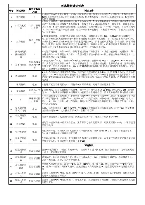
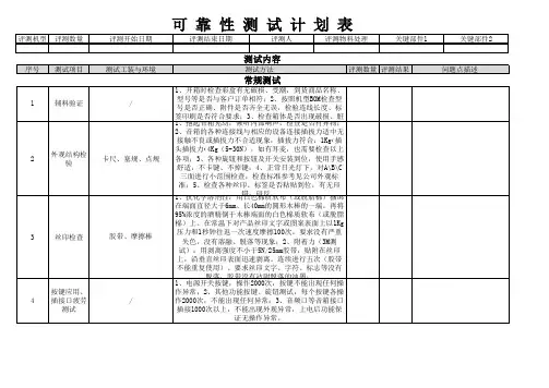
音响可靠性测试计划表
- 格式:xls
- 大小:33.50 KB
- 文档页数:3
可靠性测试作业程序(IATF16949-2016/ISO9001-2015)1.0目的:为确保不同阶段生产的产品都能符合设计要求,针对试产、进料检验、制程管制、量产等进行必要之可靠性验证,使产品经过不同的运输过程或在不同的环境下,使产品达到客户需求之规格。
2.0范围:适用于本公司所有Cable and Connector产品的可靠性测试。
3.0权责:3.1可靠性测试:品保部训练合格之人员执行之.3.2测试计划制定:量产品由品保部负责制定,新产品由工程部负责制定. 3.3测试失败分析及改善:工程部及相关单位进行分析改善.3.4测试失败改善追踪:品保部测试人员.4.0定义:(略)5.0可靠性测试时机:5.1新产品打样阶段之可靠性测试;5.2设计变更之可靠性测试;5.3量产品定期追踪之可靠性测试(至少每一个月执行一次);5.4质量有异常或客户有要求则依客户要求执行.6.0可靠性测试环境:实验室温度:23+/-5℃;湿度:75%RH以下.7.0作业内容:7.1耐久性插拔(Durability)7.1.1测试目的:评估连接器连繨插拔后,其端子电镀层磨耗程度或插拔前后之电气特性与机械特性变化;7.1.2测试对象:SATACABLE/ATA7.1.3测试依据:EIA-364-097.1.4测试方法:a.对插方式以连接器公母实配为测试原则;b.插拔速度除特别规定外,每小时不超过200次;c.插拔次数为:100次7.1.5成品类,每次抽取3pcs试验,每月执行一次.7.1.6成品此项测试在新产品打样时规定要求执行;质量出现异常时执行及客户有要求时执行.7.2摇摆测试(Bending test)7.2.1测试目的:评估线材与连接器连接效果及线材弯曲抵挡疲劳化能力. 7.2.2测试依据:EIA-364-417.2.3测试对象:USB类/其它机外线材7.2.4测试条件:7.2.5线材未能达到以上次数便断裂(open),则这次测试判为失败7.2.6针对线材类,每批抽取5PCS试验;成品类,每次抽取3pcs试验,每月执行一次.7.2.7成品此项测试在新产品打样时规定要求执行;质量出现异常时执行及客户有要求时执行;每月执行一次..7.3盐水喷雾实验(Salt Spray):7.3.1 实验目的:评估连接器金属配件及端子镀层抗盐雾腐蚀的能力﹔7.3.2 实验对象:所有五金件产品部件之来料7.3.3 实验依据:EIA364-267.3.4 实验程序:a.实验条件:*盐水浓度:5%(重量比);*试验仓之温度:35±1℃;*饱和桶温度:47±1℃;*喷雾量:1.0~2.0Ml/80cm2/h;*盐水液的PH值:6.5-7.2;b.时实验间:8H(若有特别要求,则另外规定)c.样品的放置应不互相接触,且测试面与垂直面成150度﹔d.实验完毕后除特别规定外,试样应以清水冲洗5分钟(水温不得超过38℃)必要时以软毛刷洗,洗去试验样品表面盐沉积物,然后在标准的恢复大气条件下恢复1~2H检测其样品外观.7.3.5针对五金类、CONN类,每批抽取5PCS实验。
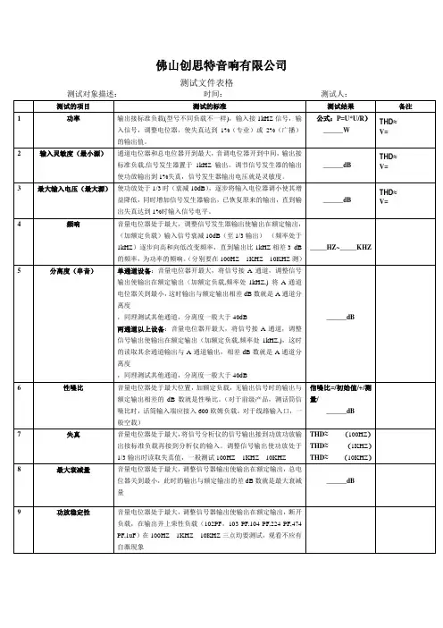
汽车音响指标测试收音部分:一FM 〔MON 1KH Z 22﹒5 KH Z DEV〕之一1、USABLE SENSITIVITY〔S/N:30dB〕30dB有用灵敏度操作:先将被测机器收正90MH Z〔98 MH Z 106 MH Z〕LEVEL 电平打在正常dB数,VOL收小到0 dB,然后去掉信号〔即打ON/OFF〕再钮毫伏表退3下〔即30 dB,退一格为10 dB〕然后调信号发生器的电平〔LEVEL〕,使没信号时的指针与有信号时的指针重复〔假设没重复,不能超过1 dB〕,最后电平〔LEVEL〕显示的dB数确实是30 dB有用灵敏度。
2、I·H·F SENSITIVITV〔75KH Z DEV 3%T.H.D〕3% 失真灵敏度操作:先将被测机收正90MH Z〔98 MH Z 106 MH Z〕打在75KH Z DEV将失真仪打在DIS 10%〔-20 dB〕档,然后钮VOL和发生器的dB数使失真仪指针不要超过3%应在3%内波动,毫伏表应指在2左右,最后发生器电平〔LEVEL〕显示的dB数确实是3%失真度。
3、-3 dB LIMITING SENSITIVTY-3 dB极限灵敏度操作:先将被测机收正98 MH Z电平〔LEVEL〕打在66dB,将VOL收小到0dB,然后减少发生器电平〔LEVEL〕dB数到毫伏表针少3个dB时停,现在,电平〔LEVEL〕所显示的dB数确实是-3dB极限灵敏度。
4、S/N RA TIO〔@1mv INPUT〕1mv=60dB+6dB 衰减=66dB信噪比操作:先将被测机收正98 MH Z电平〔LEVEL〕打在66 dB,将VOL收小到0 dB,去掉信号,然后钮毫伏表,每下10 dB,使毫伏表针不能超过0 dB,然后看指针指数是多少,再将一共打了几下的dB数加上指针指数确实是信噪比的值[例如:一共打5下〔即5档=50 dB〕加上指针指数〔比如指针指在9〕9,那么S/N=50+9=59 dB]5、I·F REJECTION中频抑制操作:先将被测机收正90MH Z,测出它的有用灵敏度dB数,再将90MH Z转为10.7 MH Z〔中频〕,然后调电平〔LEVEL〕的dB数,使波形最正时所显示的dB数减去有用灵敏度的dB数,所得的dB数确实是中频抑制的值。
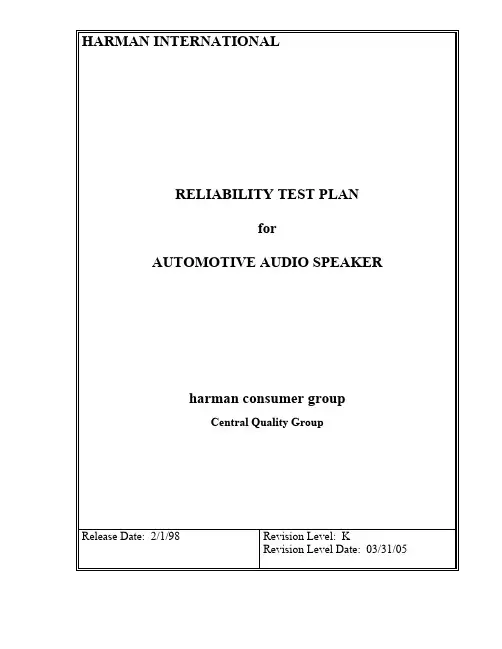
HARMAN INTERNATIONALRELIABILITY TEST PLANforAUTOMOTIVE AUDIO SPEAKERharman consumer groupCentral Quality GroupRelease Date: 2/1/98 Revision Level: KRevision Level Date: 03/31/051.0 PurposeThe purpose of this test plan is to describe the environmental and functional performancerequirements to which the speaker will undergo in order to be validated. The intent of thevalidation program is to expose the speaker to an accelerated aging process.2.0 Test PlanThis test plan details the type of tests and the number of units required for each. The sample size outlined below may change depending on Reliability Target.2.1 Test ImplementationThe full qualification test program consists of the groups listed below. This is a parallel test sequence such that each group is run independently. This test plan must be performed on at least one member of a “Product Family”. The most complex or highest power model should be chosen.Full Qualification Test SequenceGroupQuantityDV PVTest Name Spec. Sect.No.Functional TestRequirementsA 2 6Life Cycle 5.1 4.4 and 4.5B 2 6Power Test 5.4 4.4 and 4.5UV Exposure Test 5.8Impact Test 5.5C 2 6Humidity Test 5.3 4.4 and 4.5Random Vibration Test 5.6 4.4 and 4.5D 2* 6 Packaging Test (ASTM) 5.7 4.4 and 4.5For Packages up to 150 lbs (ASTM4169)Handling (Drop), First Sequence 5.7.1 4.4 and 4.5Compression Test (Vehicle StackingAssurance Level II)5.7.2 4.4 and 4.5Loose Load Vibration 5.7.3 4.4 and 4.5Vehicle Vibration 5.7.4 4.4 and 4.5Handling (Drop), Second Sequence 5.7.5 4.4 and 4.5Temperature Test 5.2 4.4 and 4.5(1) For Master Pack Shipping Option (ifavailable)5.7.9Humidity Storage Test 5.7.9.1Loose Load Vibration 5.7.3VehicleVibration 5.7.4* If packaging is available.Note 1: Unless otherwise specified, all units shall be tested in the orientation that unit will be mounted in the car.Note 2: The performance limits of the units under test will be specified in the HCG approved Engineering Test Specification (ETS) [see Section 6].2.2 Abbreviated QualificationThe abbreviated test program consists of the groups listed below. This is a parallel test sequence such that each group is run independently. These tests must be performed on all members of a “Product Family” not subjected to the Full Qualification found in section 2.1.Abbreviated Qualification Test ScheduleGroupDV PV Test Name Spec. Sect.No.Functional TestRequirementsA 2 6Life Cycle 5.1 4.4 and 4.5B 2 6Power Test 5.4 4.4 and 4.5Handling Drop Test 5.5C 2* 6Packaging Test (ASTM) 5.7 4.4 and 4.5For Packages up to 150 lbs (ASTM4169)Handling (Drop), First Sequence 5.7.1 4.4 and 4.5Compression Test (Vehicle StackingAssurance Level II)5.7.2 4.4 and 4.5Loose Load Vibration 5.7.3 4.4 and 4.5Vehicle Vibration 5.7.4 4.4 and 4.5Handling (Drop), Second Sequence 5.7.5 4.4 and 4.5* If packaging is available.Note 1: Unless otherwise specified, all units shall be tested in the normal car mounting orientation.Note 2: The performance limits of the UUT will be specified in the Engineering Test Specification.3.0 Standard Test Conditions3.0.1 Signal SourceUnless otherwise specified, all tests shall be conducted with the Audio SignalGenerator/Amplifier output configured to be balanced, less than or equal to 50-ohm source impedance, and floating. The signal source GND shall be connected to the speaker PWRGND at the speaker.3.0.2 PositionUnless otherwise specified, the speaker shall meet all requirements in the “normal mounting position”. It is defined on the Product Specification as to the horizontal or vertical position of the mounting surface.3.0.3 Room TemperatureUnless otherwise specified, all measurements shall be made at room temperature. Roomtemperature is specified as 23o C +/-3o C.3.0.4 Frequency RangeThe frequency range is specified from the -3dB point at the upper and lower operating range of the driver. This range and the limits with in that range shall specified on the ProductSpecification.3.0.5 NoiseThe products are divided into three groups, full range (multi-element), mid-bass, and sub-woofer. The type of product shall be specified on the Product Specification.Full Range will use track 13 on the Car Audio Test Disc Version 2.0: IEC noise with acrest factor of 9dB.Mid-bass will use track 14 on the Car Audio Test Disc Version 2.0: a decade of pinknoise, 50 to 500Hz (-3dB points) 12dB slopes, with a crest factor of 9dB.Sub-woofer will use track 15 on the Car Audio Test Disc Version 2.0: a decade of pinknoise, 30 to 300Hz (-3dB points), 12dB slopes, with a crest factor of 9dB.3.0.6 Music SignalThe products are divided into two groups: 1) full range (multi-element) and mid-bass, 2) sub-woofer. The type of product shall be specified on the Product Specification.Full Range and Mid-bass – track 16 on the Car Audio Test Disc Version 2.0: “Beat It”by Michael JacksonSub-woofer – track 17 on the Car Audio Test Disc Version 2.0: “Crime Stories” by MCHammer4.0 Functional RequirementsFunctional requirements are to be tested in accordance with an HCG approved product engineering specification (ETS).4.0.1 PolarizationWith the driver face down and the terminal facing toward you the Product Specification shall identify the positive terminal, which shall be labeled Pin 1 or “+”. When a positive potential is applied to the positive terminal, the cone shall move outward from the basket producingpositive pressure.Ref. IEC 268-24.0.2 DC ResistanceEnsure that the test lead resistance is factored out of this measurement. Connect the test leads to the speaker and measure the resistance in ohms with an averaging ohmmeter to ensure that ambient noise levels do not produce an EMF at the meter yielding false resistance readings.The DCR shall be within the limits specified on the Product Specification.4.0.3 ImpedanceRigidly suspend the speaker from the motor structure in free air at least 50 cm from thenearest reflecting surface. Mounting means must be minimal in bulk such that the airmovement during testing is substantially unrestricted.Measure the deviation from the Reference Sample Speaker impedance at each of the definedfrequencies. The deviation at all frequencies shall be within the limits specified on the Product Specification.4.0.4 Frequency ResponseApply a stepped sine wave sweep or a Canetics signal over the specified frequency range,using the specified frequency spacing, with the specified bandwidth smoothing per theProduct Specification, and analyze the microphone output. Calibrate the measurement system to display the 1 Watt 1 Meter equivalent sensitivity based on Z nom as specified on the Product Specification. Display the SPL and the Frequency in ISO standard 25dB/decade aspect ratio.The resultant graph of amplitude vs. frequency is defined as the frequency response. Measure the deviation from the Reference Sample Speaker sound pressure level at each of the definedfrequency bands. The deviation at all frequencies shall be within the limits specified on theProduct Specification.To verify that no damage has occurred to the Reference Sample Speaker and that the testequipment is functioning properly, the first process shall be to test the Reference SampleSpeaker against the stored data from the previous production runs. If there is a change of more than one standard deviation at any frequency, both the Reference Sample Speaker and testequipment shall be re-calibrated.4.0.5 Extraneous NoiseThe speaker assembly shall not produce extraneous noise when a dynamic test is performed.The following types of deficiencies are some typical causes of extraneous noise:Buzz: Any noise produced by a looseness of components vibrating against othercomponents.Rub: Any noise produced by the voice coil sliding or rubbing against other components.Bottoming: The noise produced by the contact of the moving system with the speakerstructure.Rattle: The random noise produced by an object trapped within the speaker strikingmoving components or any intermittent noise caused by loose electrical connections orcontrols.Frozen Coil: Absence of free excursion caused by adhesive in the magnetic gap or anoffset (loose) component of magnetic circuit.Air Noise: The noise produced by high velocity airflow through a small leak.5.0 Qualification TestingThe reliability target for all car speaker products is zero defects at 50,000 miles operation.Successful completion of the test is intended to demonstrate 90% reliability with 90% confidence.5.1 Life CycleEach speaker shall withstand 5 cycles (totaling 215 hours) of the environmental conditionsoutlined below. The speakers should be checked once a day on a regular basis. A full functional test should be performed on all units at the end of the second and fifth cycles.5.1.1 Life Cycle CalibrationThe supplied Car Audio Test Disc Version 2.0 facilitates accurate test level calibration and testing consistency by incorporating sine wave test tones (first three tracks) that are calibrated to the music tracks specified for testing.Using the RMS number from the Product Specification under the “Life Cycle” column, the level will be calibrated with the appropriate test tone (track 1 for subwoofers, track 2 for mid-bass, and track 3 for multi-element full range). Then skip to track 16 “Beat It” for full range and mid-bass or track 17 “Crime Stories” for subwoofer and repeat for the specified duration.The level of the music signal is already calibrated to the test tone.A. Over a 30-minute period, raise the temperature to 40°C with a relative humidity of 95%.B. Stabilize the temperature at 40°C with a relative humidity of 95% for 16 hours. After 6 ½hours, apply the designated music signal at 1/8th the specified RMS voltage (section3.0.6). At the end of the 16-hour period, remove the signal.C. Over a 30-minute period, raise the temperature to 90°C with a relative humidity of <20%.D. Stabilize the temperature at 90°C with a relative humidity of 20% for 8 hours. After 3hours, apply the designated music signal at 1/8th the specified RMS voltage. At the end of the 8-hour period, remove the signal.E. Over a 30-minute period, lower the temperature to 25°C.F. Stabilize the temperature at 25°C for 2 hours.G. Over a 30-minute period, lower the temperature to -35°C.H. Stabilize the temperature at -35°C for 5 hours. After 2 hours, apply the designated musicsignal at 1/8th the specified RMS voltage. At the end of the 5-hour period, remove the signal.I. Over a 1-hour period, raise the temperature to 90°C.J. Stabilize the temperature at 90°C for 5 hours. After 2 hours, apply the designated music signal at 1/8th the specified RMS voltage. At the end of the 5-hour period, remove the signal.K. Over a 30-minute period, lower the temperature to 25°C.L. Stabilize the temperature at 25°C for 3.5 hours.M. This is the end of one cycle.(See graph on next page)5.2 Temperature (Non-Operational) TestEach speaker shall withstand 24 hours of exposure to -35o C and 24 hours to 90o C inside theenvironmental chamber. The test duration should be 24 hours at each temperature with aminimum of 4 hours between temperature conditions. Let the speakers cool down to a normal room temperature before any post-test evaluation is performed. The speaker should be tested at the end of each 24-hour period.Ref. Chrysler PF 9506 2.2.2.5 Temperature Test5.3 Humidity (Non-Operational) TestEach speaker shall withstand exposure to 40o C at 95% relative humidity for 16 hours, then 90o C at 20% relative humidity for 8 hours with 15 minutes ramp between the two temperature and humidity conditions. This is considered one cycle. The total test is 5 cycles long totaling 122 hours. Leave the speakers for a minimum of 4 hours at room temperature before any post-test evaluation is performed.Ref. Chrysler PF 9506 2.2.2.1 Damp/Dry Cycling5.4 Operating Power (Noise) TestEach speaker shall withstand 100 hours of application of noise signal specified in section 3.0.5.The noise signal should be calibrated to 100% of the RMS voltage rating as specified on the Product Specification. Leave the speakers for a minimum of 4 hours at room temperature before any post-test evaluation is performed.5.4.1 Power Test Calibration ProcedureThe supplied Car Audio Test Disc Version 2.0facilitates accurate test level calibration andtesting consistency by incorporating sine wave test tones (first three tracks) that are calibrated to the noise tracks specified for testing.Using the RMS number from the Product Specification under the “Power Test” column, the level will be calibrated as follows:Subwoofer – use track 1: 50 Hz 0 dBMid-bass – use track 2: 100 Hz 0 dBFull range (multi-element) – use track 3: 1 kHz 0 dBThen skip to the appropriate noise track (Subwoofer – track 15, Mid-bass – track 14, Fullrange – track 13) and repeat for the designated 100-hour duration of speaker testing. Thelevel of the test signal is already calibrated to the test tone.NOTE: The amplifier used in the test set-up must be capable of slightly higher PEAKvoltage than the level required for testing. An oscilloscope will be used to verify theabsence of a clipped output signal (which could cause damage to the transducer andpremature failure).5.5 Impact (Non-operational) TestEach speaker (without the packaging) shall withstand one (1) drop from a height of 1 meter onto a concrete base. Each speaker shall be dropped once for each side. A total of 6 units are needed to cover all six (6) sides.Each speaker shall be visually inspected for any loose or broken parts and components. Results of the test should be treated for information purposes only and not part of the acceptancecriteria.5.6 Random Vibration (Non-operational) TestEach unit shall withstand 2 hours per axis of the Random Vibration outlined below: Z – AxisBreakpoint (Hz) Magnitude (G2/Hz)0.005550.059100.035602000.00070.000041000Total Spectral Content = 1.8 GrmsY-AxisBreakpoint (Hz) Magnitude (G2/Hz)0.009250.07680.076120.00031000Total Spectral Content = 1.685 GrmsX-AxisBreakpoint (Hz) Magnitude (G2/Hz)0.00545100.05120.00271900.000233700.000231000Total Spectral Content = 1.4 GrmsPost TestTest units shall be visually inspected for any loose or broken parts and components, followed by functional testing.Ref. Chrysler PF 9825 2.3.2.1 Vibration5.7 Packaging Test (ASTM)5.7.1 Schedule A–Manual Handling, First SequenceFor purposes of this procedure, the bottom of a small parcel is the surface on which the parcel rests in its most stable orientation. Recommended drop heights, the number of drops, thesequence of drops, and the shipping unit orientation at impact are as follows:Shipping Weight, lb (kg) Drop Height, in. (mm)0 to 20 (0 to 9.1) 24 (610)20 to 40 (9.1 to 18.1) 21 (533)40 to 60 (18.1 to 27.2) 18 (457)60 to 80 (27.2 to 36.3) 15 (381)80 to 100 (36.3 to 45.4) 12 (305)100 to 200 (45.4 to 90.7) 10 (254)Number ofImpacts AtSpecified Height Impact Orientation –First Sequence of Distribution CycletopOneTwo adjacent bottom edgesTwo diagonally opposite bottom cornersbottomOneRef: ASTM D 4169 – 99Post TestThe units should be checked for functional performance and external appearance after the test.No impaired function or concealed damage is permitted. End pads may be cracked with no separation. Cartons should have no tearing or de-bonding of the seam edge.5.7.2Compression Test: Vehicle Stacking Assurance Level IISchedule B – Warehouse Stacking and Vehicle StackingThis test is intended to determine the ability of the shipping unit to withstand thecompressive loads that occur during warehouse storage or vehicle transport. Theformula calculates the compressive load over the largest footprint of the package usinga shipping density factor. A safety factor is used to take into effect time in storage,stacking pattern, variables in container strength and atmospheric conditions(temperature, humidity). The test is to be conducted by loading the shipping unit to thecomputed load value, as calculated below. The compressive load is to be uniformlydistributed about its largest footprint. Remove the load within 3 seconds after reachingthe specified value.Formula:L = Mf*J*((l*w*h)/K)*((H-h)/h)*FL = Minimum Required Test Load=lb or NMf = Shipping Cargo Density factor = 10.0 lb/ft3 or 160 kg/m3J = conversion factor = 1 lbf/lb or 9.8 N/kgl = length of shipping unit = in or mw = width of shipping unit = in or mh = height of shipping unit = in or mK = conversion factor = 1728 in3/ft3 or 1 m3/m3H = maximum stack height = 108.0 in or 2.7mF = factor to account for individual factors described above = 7Acceptance Criteria:1. No visible damage2. Product intact internally3. Packaging components able to provide further protection4. Compression test cannot cause the outer shipping container to crease, split or tear at the joint.Test Conditioning: 73.4o F (+/-2o F) [23o C (+/-1o C)] and 50% (+/-2%) relative humidity in accordance with practice D 4332.Ref: ASTM D 41695.7.3 Loose Load Vibration Method A1—Repetitive Shock TestPlace the test specimen on the test machine platform in its normal shipping orientation. Attach restraining devices to the platform to prevent the specimen from moving horizontally off the platform and to prevent excessive rocking without restricting the vertical movement. Adjust the restraining devices to permit free movement of the specimen of approximately 10 mm (0.4 in.) in any horizontal direction from its center position. Start the vibration of the platform at a frequency of about 2 Hz and steadily increase the frequency until some portion of the test specimen repeatedly leaves the test surface. To ensure that the test specimen receives acontinuing series of repetitive shocks, a shim with a 1.6 mm (1 /16 -in.) thickness and a width of 50 mm (2.0 in.) shall be used to determine when the test specimen is leaving the testplatform. The shim should be inserted under the package a minimum of 100 mm (4.0 in.) and moved intermittently along one entire length of the package.Continue the test at this frequency for a period of 1 hour. The test may be stoppedmomentarily to inspect for damage.If the container might possibly be transported in any other orientations, test at least onecontainer in each possible orientation for the full-specified test duration.Inspect the container and its contents and record any damage or deterioration resulting from the test.Ref: ASTM D 4169 – 99, ASTM D 999 – 965.7.4 Schedule E-Vehicle VibrationPerform the test for each possible shipping orientation. Recommended intensities anddurations for the random tests are given below.Random Test:The following power spectral densities (as defined by their mode of transport, frequency and amplitude breakpoints) and test durations are recommended:Air: Assurance Level IFrequency, Hz Power Spectral Density Level, g 2 /Hz0.000420.02120.021000.00002300Overall, g rms 1.49Duration, min B180B For vehicle vibration tests in multiple shipping unit orientations, the total duration should bedistributed evenly between the orientations tested.Ref: ASTM D 4169 - 995.7.5 Schedule A–Manual Handling, Second SequenceFor purposes of this procedure, the bottom of a small parcel is the surface on which the parcel rests in its most stable orientation. Recommended drop heights, the number of drops, the sequence of drops, and the shipping unit orientation at impact are as follows:Shipping Weight, lb. (kg) Drop Height, in. (mm)0 to 20 (0 to 9.1) 24 (610)20 to 40 (9.1 to 18.1) 21 (533)40 to 60 (18.1 to 27.2) 18 (457)60 to 80 (27.2 to 36.3) 15 (381)80 to 100 (36.3 to 45.4) 12 (305)100 to 200 (45.4 to 90.7) 10 (254)Number ofImpacts AtSpecified Height Impact Orientation –Second Sequence of Distribution CycleOne vertical edgeTwo adjacent side facesTwo one top corner and one adjacent top edgeOne the drop should be in the impact orientation most likely for adrop to occur, usually the largest face or the bottom. Fordistribution cycles where any drop orientation is possible (i.e.,small parcel environment), this drop should be in the mostcritical or damage–prone orientation.Ref: ASTM D 4169 – 99Post TestThe units should be checked for functional performance and external appearance after the test.No impaired function or concealed damage is permitted. End pads may be cracked with no separation. Cartons should have no tearing or de-bonding of the seam edge.5.7.9 Master Pack Shipping Option (if available)This test is intended to determine the ability of the individual beauty boxes in a mastershipping carton to withstand the potentially abrasive environment that could occur during vehicle transport following warehouse storage. A master pack is considered to be at least six units in a larger carton. If the product master pack is less than this number, then additional master packs will be tested until the six individual unit requirement is met.The test samples will be repacked in previously untested beauty boxes free of any visibledefects before being packed in the master pack for this test. Samples will complete theHumidity Storage test in the master carton.5.7.9.1 Humidity Storage TestThe units shall be exposed to the following conditions:ConditionTemperature 40° C (+/-2° C)-2%/+3%Humidity 93%Exposure Time 48 hoursStabilization Time AfterMinimum of 8 hoursTest*Unit Configuration With Packaging*Stabilization Time is referred to as the elapsed time the unit has been out of theenvironmental chamber and allowed to reach ambient temperature and humidityconditions before continuing into the next test.The master pack will complete the Loose Load Vibration test (5.7.3). This will be followed by the Vehicle Vibration test (5.7.4).Post TestAfter the test the individual unit beauty boxes must be checked for appearance. No visiblesurface abrasion or carton degradation is permitted.5.8 Ultraviolet (UV) Exposure TestEach speaker should be place inside the UV test chamber and withstand 20 cycles of UVexposure test outlined below. The type of UV lamp should be 40 watts UV-C lamp as shown: Test Set Up:Environmental conditions as follows:Temperature is 90° C constant.Over a 30-minute period, raise the humidity from ambient to 90%.Maintain at this level for 2 hours.At the end of 2 hours, discontinue the humidity (allow to return to ambient).Continue at 90° C constant for 5 hours 30 minutes.This is one cycle (eight hours). Total test duration is 20 cycles.UV Test Environmental Profile:Int 1Post TestTest units shall be visually inspected for any degradation in parts and components, followed by functional testing. Cone and surround material should not become brittle or crack and there should be no de-bonding cone-to-dust cap or cone-to-surround. Some discoloration or fading is expected.6.0 PRODUCT SPECIFICATIONTEST PARAMETER SECTIONPosition 3.2 Hor/VertFrequency Range 3.4 Range +dB -dBNoise 3.5 Product Type RMSLevelPolarization 4.1 Lt/RtDC Resistance 4.2 Min Max NomOhmsMaxMinImpedance 4.3RangeOhmsOhms Frequency Response 4.4 Range +dB -dB。
音箱质检报告
报告编号:QA-2021-001
报告日期:2021年1月3日
检测对象:品牌ABC音箱
检测标准:GB/T 14471-2013《消费音视频设备通用技术要求》
1. 外观检测
经检测,品牌ABC音箱外观无划痕、磨损和变形等质量问题。
产品外壳材质为ABS塑料,表面采用喷涂工艺,平整一致,色彩
饱和度高。
2. 电器性能测试
经检测,品牌ABC音箱电器性能合格,以下是具体测试数据:
● 额定输入功率:10W
● 额定输出功率:5W
● 频率响应范围:65Hz~20kHz
●音频失真率:≤5%
● 信噪比:≥70dB
3. 功能测试
经检测,品牌ABC音箱功能正常,以下是具体测试数据:● 连接方式:蓝牙、AUX
● 操作方式:按键、APP遥控
● 其他功能:FM收音、闹铃等
4. 安全性能测试
经检测,品牌ABC音箱符合国家相关安全标准,以下是具体测试数据:
● 绝缘电阻:≥2MΩ
● 耐电压强度:1500V AC/1min
● 耐摔性能:产品从0.5m高度自由落下后,无明显变形和破损
5. 结论
经检测,品牌ABC音箱整体质量稳定,各项测试指标均符合国家安全标准和相关技术要求。
建议该产品继续优化细节,以提升产品的用户体验。
编写人:XXX
审核人:XXX 批准人:XXX。
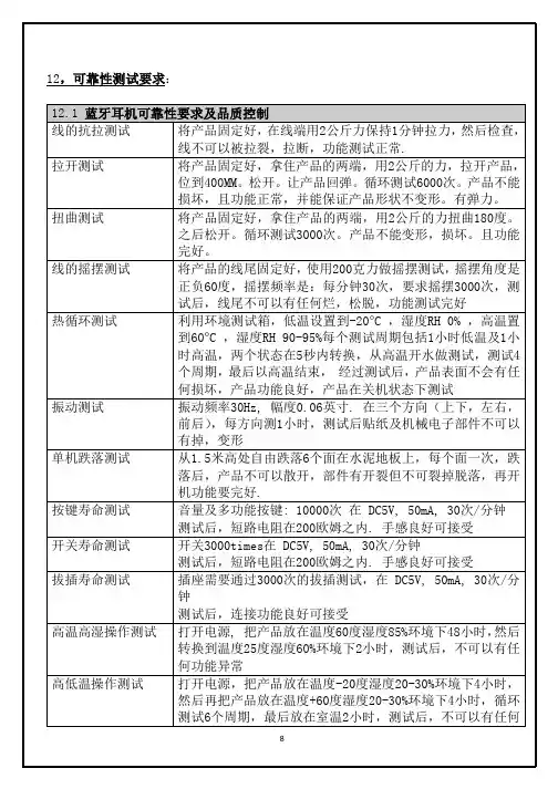
1. 目的:明确制订扬声器及耳机受话器产品的可靠性、安全性及其它特殊要求试验项目,以使大家有章可循,并做为产品开发、量产抽测依据。
5.6.3抽测数量依各项试验作业办法办理。
5.6.3如已排定之机种遇有订单取消或生产排程延后时则予顺延或取消。
5.6.4试验品依报废作业办法处理。
6 各项试验作业办法电声产品(扬声器及耳机受话器)可靠性测试要求:每项可靠性试验完成,恢复至试验前的条件,在有效频率范围内,频率响应曲线相处于规定的容差范围内。
进行每项可靠性测试以后,纯音检听不出现嗡嗡声、咔嗒声、寄生噪声。
6.1 基础实验6.1.2 低温存储试验试验对象扬声器、受话器及模组室温-20°C 1 to 10 °C/Min 96H 2H振动试验4. 试验完毕后,恢复 2H ,进行各项指标检测(外观及性能)8长周期最大功率试验试验10次1分钟开 2分钟关6.1. 9 跌落试验试验对象 扬声器、受话器 试验目的 产品抗冲击性试验测试定义. 1.5 米试验高度、 40 次跌落 .试验品装入 100 克跌落工装参考标准 IEC 60068-2-32 Basic environmental testing procedures Part :Test-TestEd:Free fall测试要求.样品数量: 20PCS.工装:扬声器 /受话器跌落工装( 100g ) .测试仪器:电声测试仪、扫频仪 .跌落工作台(大理石台面)试验步骤1.取20PCS 产品(无外观、电气不良),并记录电气参数 (FR/SPL/f0 等)2.将产品装入跌落工装3.将产品在大理石面上进行跌落(按如下图示要求)4. 试验完毕后,恢复 2H ,进行各项指标检测(外观及性能)落地方向(10 6 边+12 棱+8 角)79 7 5落地次数 2X6 边 +1X12 棱+2X8 角 =40 次落地6.1. 10 盐雾测试试验对象 扬声器、受话器、零件及模组 试验目的单体及其零件抗腐蚀能力试验1.边13126113.边4.边5.边2.边6.2.2 低温寿命测试500H1 to 10 ° C/Min6.2.3 弹片疲劳实验6.2.4 耐硝酸实验的硝酸;2.6 烤箱中干燥1 小时后,冷却至室温;2.7 把冷却后的样品放到显微镜下观察斑点大小(不允许碰伤簧片区域);附件1:附着力测试结果评定测试结果附着力结果改善动作0OK PASS-1有任何一片或多片镀金层脱落FAIL电镀质量不能接受。
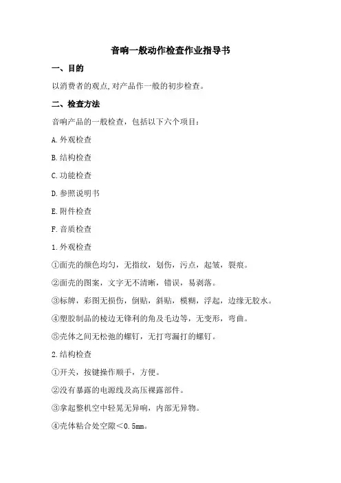
音响一般动作检查作业指导书
一、目的
以消费者的观点,对产品作一般的初步检查。
二、检查方法
音响产品的一般检查,包括以下六个项目:
A.外观检查
B.结构检查
C.功能检查
D.参照说明书
E.附件检查
F.音质检查
1.外观检查
①面壳的颜色均匀,无指纹,划伤,污点,起皱,裂痕。
②面壳的图案,文字无不清晰,错误,易剥落。
③标牌,彩图无损伤,倒贴,斜贴,模糊,浮起,边缘无胶水。
④塑胶制品的棱边无锋利的角及毛边等,无变形,弯曲。
⑤壳体之间无松弛的螺钉,无打弯漏打的螺钉。
2.结构检查
①开关,按键操作顺手,方便。
②没有暴露的电源线及高压裸露部件。
③拿起整机空中轻晃无异响,内部无异物。
④壳体粘合处空隙<0.5mm。
1. 目的:为验证我司各机型在不同工作状态、不同环境条件下的可靠性,暴露设计、材料、工艺所存在的缺陷,提高产品可靠性能和确保试验结果的正确性,特建立试验管理规范以保证原材料、成品满足客户品质要求。
2. 范围:凡与在新品开发、进料、成品、量产出货过程中,有关的原材料、半成品及成品处于可靠性测试阶段的相关事项与人员均适用;此规范适用于本公司新产品设计试验、例行性可靠性试验、重大质量问题验证和替代物料、开发工程设计变更验证等需进行可靠性试验的材料及成品。
3. 定义:QRS:品质可靠性系统(Quality Reliability System)3.1产品试验质量保证:产品在设计、试制、量产验证阶段环节,依据产品设计测试方案及试验指导作业文件,对产品正常性能、结构、工艺特性等进行常规例行、可靠性依赖性试验,以确认产品最终出货质量保证。
3.2开发设计验证:指确定新产品开发设计初期产品满足各项相关设计指标、技术参数要求及潜在失效问题特定对该设计(或变更)样品进行的试验。
3.3产品试制验证:指小批量验证确定开发设计产品的各项相关设计指标、技术参数、可靠性及稳定性要求而对小批量试制产品(或变更)样品进行的批量试验。
3.4工程变更验证:指已量产的产品因其他原因导致需要变更物料、辅料、工艺时,为保证其变更不影响原有产品品质而特定针对性进行的相关试验。
3.5例行验证:指已量产的产品在后期制造过程中,为验证其产品(或物料)品质后期是否发生变化而进行的例行常规试验。
4.权责:4.1品质部:4.1.1实验室工程师负责试验计划的拟定,对新品可靠性、例行性试验和重大质量问题验证的执行、监测,参与问题分析,提供相关试验报告,并对问题点的改善追踪,直至问题关闭。
4.2 技术部:4.2.1提供3.2项所需进行试验以OA正式《产品试验需求单》的形式提出书面申请,并提供各项所需进行试验的产品,同时视情况根据QE验证需求参与试验;4.2.2针对可靠性试验中发现的问题进行分析及拟定改善对策,并于方案导入时,做初步验证,初步验证OK后再按4.2.1项要求进行作业。
文件制修订记录1、目的为产品之可靠性实验提供作业依据。
2、适用范围凡公司产品之可告性实验均适用之。
3、定义3.1 MTBF:Mean Time Between Failures平均故障间隙时间或平均寿命。
3.2成品:公司出货状态之产品。
3.3 关联性故障:指受试样品预期会出现,如必须经维修才能排除之故障,通常为产品本身引起,它是在解释实难结果和计算可靠性特征时,必须要计入的。
3.4 非关联性故障:指受试样品非预期出现且不是受试样品本身引起的故障。
如:误用故障、从属性故障等。
它是在解释实验结果和计算可靠性特征时不需计入的,但需在实验报告中记录,以作参考。
4、职责4.1品质部QE:可靠性实验之执行,实验结果之反馈以及异常之追踪。
4.2工程部:可靠性实验异常之分析和改善。
5、作业内容5.1 可靠性实验之种类:可靠性实验按其实验目的不同包含:5.1.1环境实验5.1.1.1恒温老化实验;(动态储存)5.1.1.2高温负荷实验;(动态储存)5.1.1.3恒定湿热实验;(静态储存)5.1.1.4高温高湿高压贮存实验;(静态储存)5.1.1.6低温负荷实验;(动态储存)5.1.1.7高低温循环贮存实验;(静态储存)5.1.1.8MTBF实验(动态储存)5.2 恒温老化实验 [根据部分特殊客户要求而做]5.2.1实验目的验证产品在接近常温的恒温下之品质状况能符合客户要求。
5.2.2样品抽样5.2.2.1每一产品试作时需随机抽取20-100PCS,经检验合格(未包装)之成品进行实验。
5.2.3实验条件及方法5.2.3.1实验温度:(35±2)℃5.2.3.2实验时间:48h5.2.3.3实验负荷:Play DVD(厚碟)MP35.2.3.4实验方法:在35℃恒温下,循环播放DVD厚碟,MP3碟48小时,中途和试验后检查产品声音、动能、图像是否合符客户要求。
5.3 高温负荷实验(动态、储放)5.3.1实验目的验证产品在高温环境下之品质状况能符合客户需求。
一、目的:
通过对智能音箱批次的检验保证获得满足要求的产品。
二、范围:
适用于智能音箱产品的检验
三、内容:
抽样方案:依据GB2828,IL=II,AQL CR=0、Maj.=0.65、Min.=1.5
缺陷定义:
CR(Critical):致命缺陷,对产品使用、维修或有关人员会造成危害或不安全的缺陷,抵触安全规格要求的,或妨碍到某些主要的功能的缺陷;
MAJ(Major):不构成致命缺陷的,但可能造成故障,或对单位产品预定的目的使用性能会有严重的降低的缺陷;
MIN(Minor):不构成致命缺陷或严重缺陷,只对产品的有效使用或使用性能有轻微的影响的。
检验项目及标准:
3.1区域定义:
A面:音箱正面与上面
B面:音箱侧面与背面
C面:音箱底面
3.2检验环境要求:
相对温度:25℃±10℃
相对湿度:45%~85%
光照条件:在正常灯光照射下,光源300~500Lux,距物品1米以上
视距:眼睛与物品距离40~50cm
视角:水平垂直±45°
目视时间:物品之每一面注视3~5秒
听音检查:距离整机30CM
3.5 功能检验
四、可靠性试验:
五.引用文件无
六.记录表单无
七.附录
无。
音响部品可靠性试验操作规程
一.目的:
为了更好地执行部品出厂品质检验,保证部品在运输、贮存、使用、高低温环境下的可靠性,特制订如下规程:
二.试验项目:
按要求,分别需做:高温、低温、运输、存贮96小时放音试验等。
三.试验要求:
试验前,需经QC检测合格(并记录初始数据)方可进行试验,QA试验条件满足要求后方可进行试验。
四.试验条件、数量按要求进行。
五.异常情况处理:
在试验过程中、试验后如有异常情况发生,先需进行确认排除人为误操作或条件不合等因素,当产品确实有不良时,应按《产品质量问题处理规程》进行,并加做一次试验,以确认是否有倾向性不良。
倾向性不良需对该批产品进行修正,偶发性不良则经处理后才可通知入库,并采取防止再度发生的措施。
六.将试验结果及处理过程以报告形式记录,保存,有必要时分发有关部门。
七.。