温湿度探头使用说明
- 格式:doc
- 大小:244.00 KB
- 文档页数:4
温湿度记录仪使用说明书一、产品概述温湿度记录仪是一种用于测量和记录环境中温度和湿度数据的仪器。
该记录仪具有精确度高、操作简单、数据可靠性强等特点,广泛应用于各种需要监测和记录温湿度数据的场合。
二、产品组成1. 温湿度记录仪主机:包含显示屏、按键和数据存储功能。
2. 温湿度传感器:用于感知环境温湿度,并将数据传输至主机。
三、使用步骤1. 准备工作(1) 确保温湿度记录仪已充电或插入电源适配器。
(2) 检查温湿度传感器是否与主机连接良好。
2. 开机设置按下主机上的开机按钮,待显示屏亮起后即可进行下一步操作。
首次使用时,系统将要求进行一些基本设置,如选择语言、日期时间等。
按照屏幕提示进行设置即可。
3. 启动测量(1) 将温湿度记录仪放置到需要测量的环境中。
(2) 按下主机上的测量按钮,仪器将开始实时监测环境中的温湿度数据。
4. 数据存储与导出(1) 温湿度记录仪将实时记录测量到的数据,并在主机上进行存储。
用户可以通过查看屏幕上的数据来获取当前的温湿度情况。
(2) 若要导出数据,可以通过连接温湿度记录仪与电脑,使用附带的数据传输线将数据导出至计算机。
根据软件提示进行相应操作,用户可以选择保存数据的格式和位置。
5. 数据分析与报告用户可以使用相关软件对导出的数据进行分析和生成报告。
通过软件提供的功能,用户可以绘制温湿度曲线图、生成报表等,以便更好地了解环境变化趋势和进行数据分析。
6. 关机长按主机上的关机按钮,待显示屏关闭后即可断开电源。
四、注意事项1. 请勿将温湿度记录仪暴露于过高或过低的温度环境中,以免影响仪器的测量精度和使用寿命。
2. 使用前请确保温湿度传感器与主机连接完好,如有异常应及时联系售后服务部门。
3. 温湿度记录仪在使用过程中应尽量避免与水或其他液体接触,以防损坏仪器。
4. 使用过程中如遇异常情况或设备故障,请勿私自修理,应尽快联系售后服务部门进行维修。
五、维护与保养1. 定期清洁温湿度记录仪主机和传感器,可使用干布擦拭外表面,注意不要使用化学溶剂。
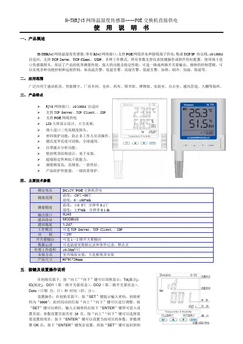
一、产品概述H-THRJ45网络温湿度传感器,带有RJ45网络接口,支持POE网线供电和接线端子供电,集成TCP/IP 协议栈,10/100M 自适应,支持TCP Server、TCP Client,、UDP、多种工作模式,所有参数支持仪表按键操作或软件轻松配置。
使用瑞士进口传感器探头,保证了产品的优异测量性能。
强大的功能及稳定性能,可选一路或两路开关量输出,独特的控制逻辑,可以实现多种功能控制和远程控制,如高温告警、低温告警、高湿告警、低湿告警、加热、制冷、加湿、除湿等。
二、应用范围广泛应用于通讯机房、智能楼宇、厂房车间、仓库、药库、图书馆、博物馆、实验室、办公室、通风管道、大棚等场所。
三、产品特点RJ45网络接口、10/100M 自适应支持TCP Server、TCP Client,、UDP支持POE网线供电LCD大屏显示设计,大方美观。
瑞士进口二代高精度探头。
密码保护功能,防止非工作人员误操作。
摄氏度华氏度可切换,全球通用。
自带露点分析功能。
壁挂吸顶结构设计,易于安装。
超强稳定性和抗干扰能力。
测量精度高,范围宽,一致性好。
产品防护性能强,一级防雷保护。
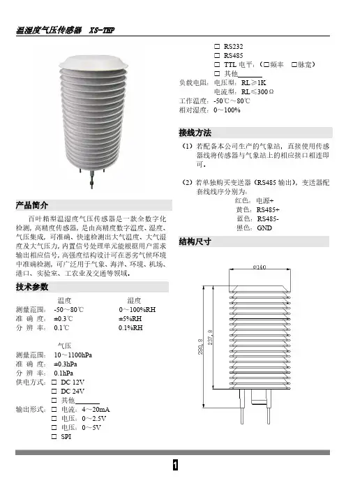
四、主要技术参数五、按键及设置操作说明在初始页面下,按“向上”“向下”键可以切换显示:Td(露点)、ID(地址)、DO1(第一路开关量状态)、DO2(第二路开关量状态)、Date(日期月:日)和时间(时:分)。
设置操作:在初始页面下,按“SET”键提示输入密码,初始密码为“0000”,此时闪动的位按“向上”“向下”键可以进行调整,按“SET”键可以移位,输入正确密码后按下“ENTER”键即可进入设置页面,参数设置页面共有26页,按“向上”“向下”键可以选择需要设置的项目,按下“ENTER”键可以设置当前项目的参数,参数调整OK后,按下“ENTER”键保存设置,再按“SET”键可返回到初始页面。
按键及设置页面介绍如右图:设置项目与对应的页码0 1OFF 为常开,ON六、安装接线说明七、注意事项1、不要直接安装在热源、冷源、或处于阳光照射下。
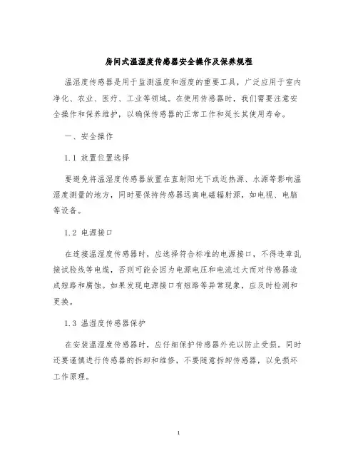
房间式温湿度传感器安全操作及保养规程温湿度传感器是用于监测温度和湿度的重要工具,广泛应用于室内净化、农业、医疗、工业等领域。
在使用传感器时,我们需要注意安全操作和保养维护,以确保传感器的正常工作和延长其使用寿命。
一、安全操作1.1 放置位置选择要避免将温湿度传感器放置在直射阳光下或近热源、水源等影响温湿度测量的地方,同时要保持传感器远离电磁辐射源,如电视、电脑等设备。
1.2 电源接口在连接温湿度传感器时,应选择符合标准的电源接口,不得违章乱接试验线等电缆,否则可能会因为电源电压和电流过大而对传感器造成短路和腐蚀。
如果发现电源接口有短路等异常现象,应及时检测和更换。
1.3 温湿度传感器保护在安装温湿度传感器时,应仔细保护传感器外壳以防止受损。
同时还要谨慎进行传感器的拆卸和维修,不要随意拆卸传感器,以免损坏工作原理。
1.4 泄漏检测温湿度传感器具有探测故障的功能,一旦发现传感器的运行出现异常,应该及时维修,避免出现泄漏现象。
在检测过程中,防止水、油、粉尘等入侵传感器内部,否则可能导致传感器损坏。
二、保养规程2.1 清洁保养温湿度传感器应在清洁干燥的环境下进行保养。
根据不同的环境和使用频率,可以定期对传感器外壳进行清洁,使用干布或吹风机进行清洗,清除附着在传感器外壳表面的污物,确保传感器的外壳清洁干燥。
2.2 维护调试温湿度传感器具有一定的维护保养要求,定期进行维护调试可以延长传感器使用寿命。
在进行维护调试时,应先关闭电源并将温湿度传感器从设备中取下,检查传感器电路板及接插件是否有松动,是否发生老化现象,及时维修和更换,确保传感器正常工作。
2.3 校准检测为了保证温湿度传感器的准确性,应定期对传感器进行校准检测。
校准检测方法根据传感器的不同型号而有所不同,具体方法可以参考设备说明书,在正确校准后可以提高传感器的测量精度和稳定性。
2.4 注意使用环境在使用温湿度传感器时,应注意使用环境的温度、湿度等因素对传感器的影响,避免在恶劣的环境中长时间使用传感器,以免出现故障。
仓库温湿度传感器安全操作及保养规程1. 引言仓库温湿度传感器是一种常见的用于仓库环境监测的设备,它可以实时监测仓库内的温度和湿度值,帮助仓储人员及时发现环境问题并采取相应的措施。
然而,为了保证传感器的正常使用和延长使用寿命,必须注意设备的安全操作和保养。
本文就仓库温湿度传感器的安全操作及保养规程进行详细说明。
2. 安全操作规程2.1. 环境适应性检查在进行温湿度传感器的安装前,必须先进行环境适应性的检查,确保设备可以在所处的环境下正常工作。
2.2. 正确安装设备仓库温湿度传感器的正确安装需要遵循一定的步骤和操作规程,例如选择合适的安装位置、采用适当的安装工具、确保设备固定牢固等。
2.3. 避免物理损坏在安装完成之后,必须确保传感器不会遭受碰撞、挤压等物理损坏,否则可能导致设备损坏或读数不准确。
2.4. 避免电气损坏温湿度传感器需要连接电源进行工作,因此必须注意避免电气损坏,如防静电、避免接触电气元件等。
2.5. 防水防潮在安装温湿度传感器时,必须注意防水防潮,避免设备进水或受潮,影响设备的正常工作。
2.6. 周期性检查维护为了保证设备的正常工作和延长使用寿命,必须定期进行检查和维护,如检查设备连接状况、清理设备表面、更换电池等。
3. 保养规程3.1. 清洁定期清理温湿度传感器设备表面的灰尘和脏污,避免污染设备,影响读数准确度。
3.2. 维护如发现设备接线松动或设备损坏,需要及时维护处理。
3.3. 更换电池设备电池不足时,读数会出现异常,因此必须定期更换电池。
3.4. 合理使用及存储在使用过程中,对温湿度传感器进行合理使用,避免过度使用或强行使用。
同时,需要注意存储环境,避免长时间放在高温、潮湿的环境中。
4. 总结仓库温湿度传感器在仓储管理中起到了重要的作用,为了确保设备的正常使用和延长使用寿命,必须注意设备的安全操作和保养。
通过本文对温湿度传感器的安全操作及保养规程的介绍,相信可以为仓储管理工作提供更多的帮助和参考。
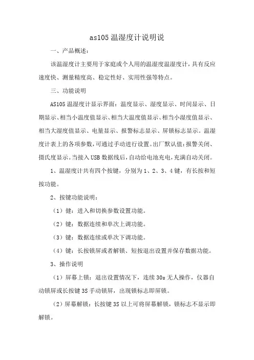
as105温湿度计说明说一、产品概述:该温湿度计主要用于家庭或个人用的温湿度温湿度计,具有反应速度快、测量精度高、稳定性好、实用性强等特点。
三、功能说明AS105温湿度计显示界面:温度显示、湿度显示、时间显示、日期显示、相当小温度值显示、相当大温度值显示、相当小湿度值显示、相当大湿度值显示、电量显示、报警标志显示、屏锁标志显示。
温湿度计表上的各项参数,可通过手动进行设置。
出厂默认值:报警关闭、摄氏度显示。
当接入USB数据线后,自动给电池充电,充满自动关闭。
1、温湿度计共有四个按键,分别为1、2、3、4键,有长按和短按功能。
2、按键功能说明:(1)健:进入和切换参数设置功能。
(2)键:数据连续和单次上调功能。
(3)键:数据连续或单次下调功能。
(4)键:长按锁屏或者解锁、短按退出设置并保存数据功能。
3、操作说明(1)屏幕上锁:退出设置情况下,连续30s无人操作,仪器自动锁屏或长按键3S手动锁屏,出现锁标志即屏锁。
(2)屏幕解锁:长按键3S以上可将屏幕解锁,锁标志不显示即解锁。
(3)外置探头接入标志:外部单温或者温湿度传感器接入,屏幕上外部传感器标志会亮,否者不亮。
(4)温度上、下限值设置:短按键以上进入设置,默认是1.CH 或按键切换到2.CL,按和键可设置用户需的温度上、下限值,设置范围:-40℃到+100℃(-40℉到212℉)。
注:温度上限值不能低于温度下限值。
(5)湿度上、下限值设置:短按键进入设置,按键切换到3.HH或4.HL,按键和键可设置用户需的湿度上、下限值,设置范围:0到99.9%RH。
注:湿度上限值不能低于湿度下限值。
(6)5.Ar:表示报警设置,ON:启动报警功能,OFF:关闭报警功能。
(7)6.CF:表示单温转换,C:摄氏度为单位,F:华氏度为单位。
(8)系统时间:按SET键可切换至相应的设置,对应的值会不停的闪烁。
注:年份、月份只能单次设置,长按UP或者DOWN键无效。
4、报警状态显示:当报警功能启动时,屏幕上报警标志亮,若温湿度的当前值过或低于设定的温湿度上、下限值时,相对应的报警标志不停的闪烁,同时蜂鸣器会每隔1秒钟报警4次。
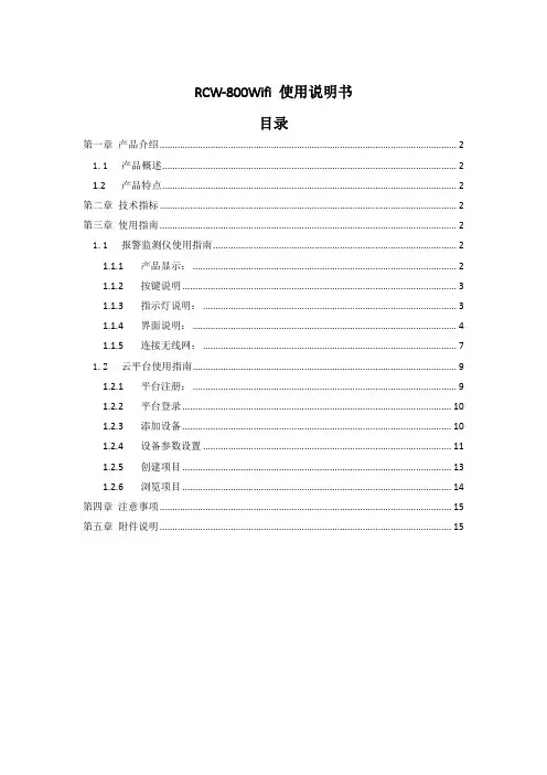
RCW-800Wifi 使用说明书目录第一章产品介绍 (2)1.1产品概述 (2)1.2产品特点 (2)第二章技术指标 (2)第三章使用指南 (2)1.1报警监测仪使用指南 (2)1.1.1产品显示: (2)1.1.2按键说明 (3)1.1.3指示灯说明: (3)1.1.4界面说明: (4)1.1.5连接无线网: (7)1.2云平台使用指南 (9)1.2.1平台注册: (9)1.2.2平台登录 (10)1.2.3添加设备 (10)1.2.4设备参数设置 (11)1.2.5创建项目 (13)1.2.6浏览项目 (14)第四章注意事项 (15)第五章附件说明 (15)第一章产品介绍1.1产品概述RCW-800WIIF库狗温湿度远程报警仪,是一款基于物联网技术的高新技术产品,产品广泛应用于食品、餐饮、物流以及HACCP体系认证的行业。
通过WIFI数据传输方式,结合冷链物联网平台,客户通过浏览器或者智能手机终端在线实现实时监控数据远程查看和管理数据。
同时还可以通过平台报警,蜂鸣器报警提示功能。
RCW-800WIIF为1温1湿类型,设备内置充电锂电池,断电仍可提供实时数据上传、平台报警服务。
1.2产品特点●采用高灵敏度探头,反应快,灵敏度高。
●断电续航,内置电池可持续工作至少6小时。
●可设定温湿度报警阈值,超出设定阈值LED灯闪烁、蜂鸣器鸣叫等提示报警。
●可设定上传间隔时间,自由控制数据记录。
●报警仪本机可记录20000组数据,服务器不受存储组数限制。
●连接Wifi接入点,采集数据实时上传云平台。
●灵活导出数据,可通过云平台导出多种格式数据。
第二章技术指标产品型号:RCW-800Wifi供电电源:5V/1A(DC)测温范围:-40℃~+80℃测温精度:-20℃~+40℃:±0.5℃;其他±1℃温度显示分辨率:0.1℃温度传感器类型:NTC热敏电阻温度传感器线长:5米;测湿范围:10%RH~95%RH测湿精度:±5%RH湿度显示分辨率:0.1%RH湿度传感器类型:霍尼韦尔湿度传感器线长:2米上传间隔时间:1分钟~24小时离线记录容量:20000组报警输出:LED指示灯、蜂鸣器、平台提示通信接口:Wifi备用电池:3.7V 1100mAh 锂电池第三章使用指南1.1报警监测仪使用指南1.1.1产品显示:1.1.2按键说明1) 触控按键:a) 【】:进入菜单、确定选中项; b) 【】、【】选择键:选择菜单选项,点击上选择键,选中上一个选择;点击下选择键,选中下一个选项;当光标到最上面或最下面时,按上键或下键循环显示; c) 【】、【】选择键:更改参数值,点击左选择键,参数值减小;点击右选择键,参数值增大;当光标到最上面或最下面时,按上键或下键循环显示; d) 【】:退出当前界面,返回上一界面; 2) 亮屏键\熄屏键:当LCD 屏亮时,按击亮屏键 LCD 屏幕熄灭,当LCD 屏灭时,按击亮屏键 LCD 屏幕亮; 3) 开关键:通过拨动拨码开关控制设备开关机; 4) 复位按键:按住复位键4秒,Wifi 接入点恢复出厂默认值,可重新连接WIFI 设置;1.1.3 指示灯说明:1) 电源指示灯:外部电源接通时,电源指示灯(绿色)常亮;无外接电源,由电池对设备供电时电源指示灯熄灭;2) 报警指示灯:正常状态时不亮,超限报警时,指示灯(红色)以每秒1次的频率闪烁;当前时间报警指示触控按键锁屏键采集显示区1.1.4界面说明:1)开机画面:开关机:1.如果需要开机,滑动设备背面开关机键,设备开机并显示开机画面;2.如果需要关机,再次滑动开关机键即可;2)主界面:1.开机后,跳过开机画面,自动进入主界面;2.点击【】键进入参数设置主界面;3)参数设置主界面:1.点击【】、【】键切换选择菜单项;2.点击【】键进入选中菜单项界面;3.点击【】键返回主界面;4.点击【】、【】键无反应;4)报警参数设置:1.温度报警范围:-40℃~70℃;湿度报警范围:10%~95%;2.点击【】、【】键切换选择参数项;3.点击【】、【】键循环改变选中参数项的参数值,步进为1增加或减少;4.点击【】键保存参数并返回参数设置界面;5.点击【】、【】键无反应;5)数据传输功能:1.数据传输功能:包含开启和关闭两个参数值,默认开启;2.数据上传间隔:参数范围 1min ~60分钟,默认1分钟;若需要设置超过60分钟的上传间隔时间,可通过平台设置参数,最大可设置为24小时;若上传间隔时间已设置超过60分钟,通过按键修改参数时,界面参数值显示为60;3.点击【】、【】键切换选择参数项;4.点击【】、【】键循环改变选中参数项的参数值;5.点击【】键保存参数并返回参数设置界面;6.点击【】键无反应6)语言选择和待机时间:1.语言选择:包含中文和英文两个参数值,默认英文;2.屏幕待机:包含1分钟、5分钟、关闭3个参数值;3.点击【】、【】键切换选择参数项;4.点击【】、【】键循环改变选中菜单项的参数值;5.点击【】键保存参数并返回参数设置界面;6.点击【】键无反应;7)恢复出厂设置:1.恢复出厂设置:包含是和否2个参数值;2.点击【】、【】无反应;3.点击【】、【】键循环改变选中菜单项的参数值;4.当菜单值为“是”,点击【】,弹出是否恢复出厂设置确认界面,点击【】,设备重启,参数值恢复出厂设置。
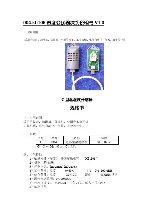
004.kh106湿度变送器探头说明书V1.01、应用范围适用于仪表、加湿机、除湿机、空调等设备、工业机械、电气自动化、气象、农业等行业。
C型温湿度传感器规格书一、应用范围:适用于仪表,加湿机,除湿机,空调设备等用途工业机械,电气自动化,气象,农业等行业。
三、电气特性1)敏感元件(湿度):法国湿敏电容“HS1101”2)供电:5V±5%3)耗电电流:5mA max.(2mA avg.)4)工作范围:温度0~60℃湿度0%- 100%RH5)储存条件:温度-20~70℃湿度95%RH以下6)湿度变送范围:0~100%RH7)精度(湿度):±3%RH (在25℃,输入电压=5V)8)输出信号:9)温度系数: ±3%RH (30~90%RH , 温度范围10~40℃ 基准点25℃)10)电源电压系数:±5%RH (输入电压=5V ,30~80%RH 电压范围:4.75~5.25V)11)敏感元件(温度):NTC 热敏电阻、LM35等可选。
四、标准测试条件㈠测试条件:室温25℃,电压5V㈡ 测试仪器1、湿度发生器:高精度恒温恒湿度试验箱 :巨孚2、标准:GE 公司光电露点仪3、电压表V/%RH0.20.40.60.811.21.41.61.822.22.42.62.830102030405060708090100%RHV图一五、外型尺寸 单位:mm①、T温度信号输出②、GND地③、H湿度输出④、VCC电源正六、可靠性通过常规冲击试验,振动试验,冷热试验,高湿试验,温度循环等试验PCB表面喷有防水胶,95%RH以下可正常长期工作。
七、注意事项1)避免将直流电直接加在敏感元件上。
2)避免将元件长期放在结露和干燥的环境中以及以下环境。
A、盐雾B、酸性或氧化气体,例如二氧化硫,盐酸等3)由于湿敏电容的容量为PF级,严禁将湿敏电容从线路板焊下,再引线焊接出来,会导致湿度示值漂移。
温湿度记录仪操作流程说明书1. 简介温湿度记录仪是一种用于监测和记录环境中温度和湿度的设备。
本操作流程说明书将向您介绍如何正确操作和使用温湿度记录仪。
2. 准备工作在开始操作之前,请确保已经准备好以下物品:- 温湿度记录仪设备- 电池或电源适配器- 温湿度传感器- 计算机(或移动设备)和数据传输线(如 USB 线)3. 基本操作步骤a. 安装电池或连接电源适配器:根据设备说明书的要求,安装电池或连接电源适配器,确保设备有足够的电力供应。
b. 连接温湿度传感器:将温湿度传感器插入设备上指定的接口,并确保插入牢固。
c. 开机和设置:按下设备上的开关键启动设备,并按照设备说明书提供的方法,设置温度和湿度的测量单位、采样间隔等参数。
d. 放置记录仪:将温湿度记录仪放置在要监测的环境中,并确保传感器暴露在空气中。
e. 数据记录和存储:温湿度记录仪将按照设置的采样间隔自动记录环境中的温度和湿度数据,并将其存储在内部存储器中。
f. 数据传输:根据需要,将记录仪与计算机或移动设备连接,使用数据传输线将数据传输到计算机或移动设备上的相应软件中进行进一步分析和处理。
g. 数据分析和报告生成:使用相关软件,对传输到计算机或移动设备上的数据进行分析和处理,并生成相应的报告和图表。
4. 注意事项在操作和使用温湿度记录仪时,请注意以下事项:- 请按照设备说明书提供的方法正确操作设备,避免不必要的损坏或故障。
- 请确保温湿度传感器插入牢固,并暴露在要监测的环境中以获得准确的数据。
- 定期检查电池电量,并及时更换电池以确保设备正常运行。
- 在进行数据传输前,请确保设备与计算机或移动设备的连接稳定,并使用正规和可信赖的数据传输线。
- 在数据分析过程中,请根据需要进行准确的数据处理和结果生成。
5. 故障排除如果在使用温湿度记录仪时遇到任何故障或问题,请参考设备说明书提供的故障排除方法,或联系设备供应商寻求帮助和支持。
6. 结束操作在使用完温湿度记录仪后,请将设备关机,并根据需要将其存放在干燥和安全的地方,以防止损坏或丢失。
现场检测温湿度计操作规程现场检测温湿度计操作规程一、引言温度和湿度是在很多工业和实验室应用中必须进行监测和控制的两个重要参数。
温湿度计是一种可以准确测量和显示温度和湿度的仪器。
为了确保温湿度计的正确使用和保养,制定了以下操作规程。
二、适用范围本操作规程适用于一切现场需进行温湿度测量的情况,包括工业生产、实验室、仓储等场所。
三、操作步骤1. 准备工作a. 检查温湿度计的外观,确保其无明显损坏;b. 检查电池电量,确保电池充足;c. 根据测量区域的需求,选择合适的测量范围和测量单位。
2. 打开温湿度计按下温湿度计的开关按钮,确保显示屏亮起。
若温湿度计支持设置参数,根据需要进行参数设置。
3. 测量温度a. 将温湿度计的温度探头插入需要测量的区域,确保探头与空气充分接触;b. 等待温湿度计稳定显示温度数值,记录下来。
4. 测量湿度a. 将温湿度计的湿度探头置于需要测量的空气中,确保探头与空气充分接触;b. 等待温湿度计稳定显示湿度数值,记录下来。
5. 关闭温湿度计按下温湿度计的开关按钮,确保显示屏熄灭。
6. 清洁和维护a. 使用干净、柔软的布擦拭温湿度计的外观,避免使用有腐蚀性和蓄电性的清洁剂;b. 定期检查和更换温湿度计的电池,确保电池正常工作;c. 根据实际情况,定期进行校准和维护,以确保温湿度计的准确性和可靠性。
四、安全注意事项1. 操作人员应熟悉温湿度计的使用说明书,确保正确操作;2. 在测量过程中,避免温湿度计的探头受到外界物体的阻挡,以免影响测量准确性;3. 使用过程中若发现温湿度计异常情况,应及时停止使用并进行检修;4. 使用电池供电的温湿度计使用过程中,不得将电池短路或直接放置于高温环境中;5. 严禁打开温湿度计外壳,避免发生触电、短路等危险。
五、附录1. 温湿度计使用说明书2. 温湿度计的校准和维护记录表3. 温湿度计维修和安全事故处理流程以上即为现场检测温湿度计的操作规程,希望能够对您有所帮助。
高精度温湿度传感器安全操作及保养规程前言高精度温湿度传感器是现代工业、农业等各个领域中必不可少的设备之一。
正确的使用和保养温湿度传感器可以保证其正常运行、提高工作效率和延长使用寿命。
为了确保操作的安全性和稳定性以及提高传感器的使用效率,制定本安全操作和保养规程。
安全操作规程1.检查传感器电源是否接好。
在使用传感器前,必须确保传感器的电源线已经正确接好电源,确认传感器通电后再开始使用。
2.避免过度拉拽传感器导线。
在移动传感器时,避免过度拉拽传感器的导线,应该用手形成环绕在手中后才进行移动。
长期过度拉拽会导致导线老化,造成传感器损坏。
3.避免传感器接触水和化学物质。
温湿度传感器不能接触水、酸性物质、碱性物质等化学物质,否则会引起短路和腐蚀,造成传感器损坏。
4.注意传感器使用环境。
传感器不能被安置在过于潮湿或过于干燥的境地,以免影响到传感器的读数准确性和使用寿命。
5.确保传感器的气流通畅。
传感器需要保持通风良好的环境,以确保信号稳定,不要堵塞传感器前面板。
6.确保传感器采集频率合理。
传感器在使用时应该根据需要对采集频率进行设置,不要设置过高或过低的采集频率,否则会影响传感器的使用寿命。
7.避免传感器震动。
传感器在运输过程中,应该避免剧烈震动,震动会导致传感器内部元件失灵,降低传感器的使用寿命。
保养规程1.定期清洁传感器。
长期使用传感器会积累灰尘和污垢,影响读数的准确性,应该定期进行清洗。
清洗时,应该使用干净的软布轻轻擦拭传感器,避免受潮。
2.定期校准传感器。
校准传感器是保证传感器稳定性的重要环节,建议每3-6个月对传感器进行校准。
3.注意传感器电源的电压和功率。
传感器在使用时,必须严格按照说明书上的电源电压和功率进行安装和使用。
传感器连接电源时要按正确极性,不要接反或短路。
4.定期更换传感器电池。
对于使用电池的温湿度传感器,应该定期更换电池,以确保传感器工作一直稳定。
建议在使用6个月后更换电池。
5.注意传感器存储温度和湿度。
温湿度传感器产品说明书ZZ-THS-ST目录温湿度传感器产品说明书 (1)ZZ-THS-ST (1)1.产品简介 (3)1.1产品概述 (3)1.2功能特点 (3)2.参数详情 (4)2.1外形尺寸图 (4)2.2基本参数 (4)2.3模拟量参数含义 (5)2.3.1模拟量4-20mA电流输出 (5)2.3.2模拟量0-10V电压输出 (5)2.3.3模拟量0-5V电压输出 (6)2.4通讯协议 (6)2.4.1通讯基本参数 (6)2.4.2数据帧格式定义 (7)2.4.3寄存器地址 (9)2.4.4通讯协议示例以及解释 (9)3.安装使用 (11)3.1系统架构图 (12)3.1.1直接接电脑或者PLC (12)3.1.2网络传输使用 (13)3.2接口说明 (13)3.3接线说明 (14)3.3.1典型四线制接线方式 (14)3.3.2典型三线制接线方式 (16)3.4协议调试(只适用于485输出型) (17)4.包装售后 (21)4.1产品包装清单 (21)4.2联系方式 (21)4.3质保与售后 (21)4.4免责声明 (22)1.产品简介1.1产品概述该变送器广泛适用于农业大棚/花卉培养等需要温湿度监测的场合。
传感器内输入电源,感应探头,信号输出三部分完全隔离。
安全可靠,外观美观,安装方便。
1.2功能特点●探头灵敏度高●信号稳定,精度高●测量范围宽、线形度好●防水性能好、使用方便●便于安装、传输距离远等2.参数详情2.1外形尺寸图2.2基本参数参数技术指标温度测量范围-40℃-80℃(可定制)湿度测量范围0-100%RH温度测量精度±0.5℃(25℃典型值)湿度测量精度±3%RH(5%RH-95%RH,25℃典型值)(1)温度长期稳定性≤0.1℃/y温度长期稳定性≤1%/y通讯端口RS485Modbus协议/模拟量接口(电压型或者电流型)供电电源12V-24V DC最大功耗≤0.3W(@12V DC,25℃)外形尺寸110×85×44mm3电流输出类型4-20mA电流输出负载≤600欧姆电压输出类型0-5V/0-10V电压输出负载≤250欧姆工作压力范围0.9-1.1atm2.3模拟量参数含义2.3.1模拟量4-20mA电流输出电流值温度湿度4mA-45℃0%20mA115℃100%计算公式为P=(I-4mA)*6.25%其中I的单位为mA。
洁净室温湿度探头校准方法
首先,我们需要准备一台高精度的温湿度校准仪器,确保其精度和稳定性能够满足校准要求。
接着,将温湿度探头安装到校准仪器上,并将校准仪器放置在已知温度和湿度的环境中,等待一段时间使其稳定下来。
接下来,根据校准仪器的操作说明,进行温湿度探头的校准操作。
通常情况下,校准过程包括零点校准和斜率校准两个步骤。
零点校准是指在零点温度和湿度下对探头进行调零,而斜率校准则是根据已知温湿度值对探头的输出进行调整。
在进行校准过程中,需要严格控制环境条件,确保校准仪器和温湿度探头处于稳定的环境中,避免外界因素对校准结果的影响。
校准完成后,记录下校准仪器和温湿度探头的读数,以便后续的验证和比对。
最后,校准完成后,需要对温湿度探头进行验证,验证方法可以使用不同的校准仪器或者与其他已经校准过的温湿度探头进行比对。
通过验证,可以确保温湿度探头的准确性和可靠性。
总之,洁净室温湿度探头的校准是确保洁净室环境监测准确性的关键步骤,通过严格的校准和验证,可以保证温湿度探头的可靠性和稳定性,为洁净室的正常运行提供可靠的数据支持。
MP 101AHUMIDITY TEMPERATURE PROBE INSTRUCTION MANUALCONTENTSDESCRIPTION (3)OPERATION (3)INSTALLATION (4)MAINTENANCE (7)CALIBRATION BASICS (7)CALIBRATION PROCEDURE (8)SPECIFICATIONS (11)PLEASE, READ THIS FIRST•Check the product for any physical damage that may have occurred during shipment. We carefully pack and routinely insure all shipments. If any damage has occurred, it is yourresponsibility to file a claim with the carrier, prior to returning the damaged product. Pleasenote that our warranty does not cover damage during shipment.•Prior to installation, get fully familiarized with important information provided in this manual such as: supply voltage, electrical connections, adjustments, operating limits. A label located on the barrel of the probe provides the main technical data.•Do not unnecessarily remove the sensor protection (slotted cap or dust filter) from the probe.Both sensors (humidity and temperature) can be mechanically damaged by careless removal of the protection.Each ROTRONIC instrument is carefully calibrated before shipment. No further adjustmentsshould be required before installation. If you have any question or problem, please call our service department at 631/427-3898 and press 5 (or ask for extension 21).DESCRIPTIONThe MP101A is a combined humidity and temperature probe designed primarily for outdoor applications. Operation from a DC voltage and low power consumption make the MP101A particularly suitable for operation at remote locations. Energizing of the probe is required for only 0.25 seconds during each measurement. The linear output signals are consistent with the requirements of most data acquisition systems.Use of the HYGROMER C94 capacitive humidity sensor results in exceptional resistance to contaminants. Advanced filter technology provides further protection. The MP101A can be used over long periods of time without any maintenance or recalibration.The MP101A is available in 2 basic configurations:• MP101A-C4/5 with 2 meters hard wired cable terminated by a connector (4 or 5-pin).• MP101A-T7 with a 7-pin connector directly on the probe.The probe MP101A-C4 is supplied with a 4-pin CANNON connector and is fully interchangeable with the previous probes of the MP100 series. When the application requires a total length of cable in excess of 6.5 ft (2 meters), either the probe MP101A-C5 or the probe MP101A-T7 should be used. Both probes feature a compensation that eliminates potential errors resulting from cable resistance for lengths up to 330 ft (100 meters).OPERATION1. Power SupplyThe MP101A accepts an unregulated supply voltage between 4.8 and 30 VDC. The current consumption is 10 mA.The MP101A does not have to be continuously energized. Measurements require that the probe be energized for 0.25 seconds after which the power can be turned off to conserve energy.2. Output SignalsThe MP101A provides two linearized voltage output signals: one for humidity and the other for temperature.Relative humidity Output Signal (linear) 0...1.0 VDC = 0 to 100%RHTemperature Output Signal (linear) Standard: -0.4..0.6 VDC = -40..+60°COptional: 0.0..1.0 VDC = -40..+60°COptional: 0.0..1.0 VDC = -30..+70°CDo not connect a load to the output with an impedance of less than 1000 Ω.3. Temperature LimitsThe MP101A can operate within -40°C and +60°C. Operating the MP101A outside of the temperature limits may result in inaccurate measurements and can permanently damage the unit.4. Humidity LimitsThe MP101A can operate within 0 and 100 %RH. Direct condensation on the sensors does not damage the sensors. However, the humidity sensor will not provide correct readings as long as condensation is present. The MP101A provides a humidity output that is referenced to the saturated water vapor pressure above liquid water. With this reference, the maximum humidity temperatures below freezing is as follows:100 %RH at 0°C 95 %RH at -5°C 91 %RH at -10°C87 %RH at -15°C 82 %RH at -20°C 78 %RH at -25°C75 %RH at -30°C5. Temperature CompensationPractically every make of relative humidity sensor requires a compensation for the effect of temperature on the humidity output signal in order to measure accurately over a wide range of temperature conditions. In the specific case of an instrument using a capacitive sensor, compensation is required because the dielectric characteristics of both the water molecule and the hygroscopic polymer used in the sensor vary with temperature. The electronic circuit of the MP101A uses data from the temperature sensor to automatically compensate the effect of temperature on the accuracy of humidity measurement.6. Sensor ProtectionAlways use the dust filter provided with the probe to protect the sensors.INSTALLATION1. Probe LocationInstall the probe so that the local conditions at the sensors are typical of the environment to be measured:• Use either a shield or a shelter to protect the probe and sensors from direct exposure to solar radiation and precipitation. Several shields are available from ROTRONIC (see specifications).• In an open field, install the probe at least 3.3 feet (one meter) above ground. Increase this distance if the ground surface is concrete or black top (such as above a roof).2. GroundingOperation of the MP101A does not require that the unit be electrically grounded. However, we strongly recommend grounding the (-) side of the supply voltage to the probe.3. WiringBefore connecting the probe, please make sure that there is no wiring error. Improper wiring may damage the probe.The different models of connector supplied with the MP101A are designed for outdoor use. Since the probe will have to be removed from its location to be calibrated from time to time, we do notrecommend replacing the cable supplied with the probe cable with a longer cable. Instead of this, use an extension cable with a maximum length of up to 330 feet (100 meters).MP101A-C4: To provide interchangeability with older probes, a 4-pin connector is used on this model. Preferably, this probe should not be used with an extension cable since this additional cable length will not be compensated. The ground wire of the supply voltage and the common wire of the output signals are soldered to the same pin at the 4-pin connector.A or 1: Green Supply Voltage +B or 2: Yellow & Shield Ground and CommonC or 3: White %RH (+)D or 4: Brown Temp. (+)Amphenol Connector Part Numbers: Plug: MS3106A-14S-4PClamp: MS3057-6AMating: MS3101A-14S-4SMP101A-C5 and MP101A-T7: Both models permit the use of up to 330 feet (100 meters) extension cable. A 5-pin connector (MP101A-C5) or a 7-pin connector (MP101A-T7) is used to separate the ground wire of the supply voltage from the return (or common) wire of the output signals. On a long extension cable, the 10 mA flowing to the probe would otherwise create a voltage drop and an error on the output signals. For compensation purposes, the two wires should be joined together at the end of the extension cable (see drawing below).ExtensionA or 1: Red Supply Voltage (+)B or 2: Black CommonC or 3: Green %RH (+)D or 4: White Temp. (+)E or 5: Shield GroundMP101A-C5MP101A-T71: Green Supply Voltage (+)2 & 3: Black Ground4: Red Temp. (+)5: Yellow Common6: Blue %RH (+) Amphenol Part Number: Plug MS3106A-14S-5PClamp MS3057-6AMating MS3101A-14S-5SConsult factory for part number.GreenYellow CommonWhiteBrownGroundBrownWhiteMAINTENANCE1) Cleaning or Replacing the Dust Filter:The dust filter should be cleaned from time to time, depending on the conditions of measurement. Cleaning should be done without removing the filter from the probe. Gently wipe the filter with a solution of water and mild detergent. If this does not remove most of the stains, the filter should be replaced. To do this, unscrew the filter from the probe.When removing the filter, make sure that the sensors do not get caught. The humidity sensor is sometimes mistaken for a "white paper tag". Do not remove from the probe!Before putting on a new dust filter, check the alignment of both sensors with the probe. The wires that connect the sensors to the probe are very thin and bend easily. If this happens, correct the alignment by holding the sensor very gently with a pair of small flat nosed pliers. Do not puncture the sensor with sharp pliers or tweezers or pull too hard on the sensor.2) Periodic Calibration Check:Long term stability of the humidity sensor is typically better than 1 %RH per year. For maximum accuracy, calibration of the unit may be verified every 6 to 12 months.Applications where the probe is exposed to significant pollution may require more frequent verifications. The calibration procedure is described in detail in this manual.Both the Pt 100 RTD temperature sensor and associated electronics are very stable and should not require any calibration after the initial factory adjustment.CALIBRATION BASICS1. Temperature CalibrationThe stability of the Pt100 RTD sensor used to measure temperature is such that temperature calibration in the field is seldom required.In order to be able to correctly evaluate the accuracy of the temperature measurements provided by the probe, you should be able to meet the following requirements:• Both the probe and a reference thermometer should be ventilated with the same stream of air. Any dust filter used to protect the sensors should be removed from the probe. If the probe has a slotted cap, this should be left on the probe.• Air velocity should be within the limits of 200 to 500 feet/minute (1 to 2.5 meters/second). Any comparison between two instruments at velocities under 200 feet/minute may not be valid. Air velocity above 500 feet/minute may damage the unprotected humidity sensor.• The temperature of the air stream should be constant or at least it should not change at a rate that is less than 10 times the shortest time constant of either the probe or reference thermometer.If you are not able to meet the above requirements, you cannot correctly check the accuracy of temperature measurement and should not attempt to calibrate temperature.2. Humidity CalibrationWhen calibrating humidity, temperature stability is the single most important requirement. Do not calibrate unless the probe is at room temperature (20 to 25°C) and this temperature is stable to ±0.25°C or better during the period of time required for each calibration point. Do not calibrate close to an air vent or a heater, in direct exposure to sun rays, etc. If necessary during calibration,place the tip of the probe with the calibration device on it (see below) inside an insulating box filledwith sand.a) Calibration Device and Humidity Standards:The calibration device is a small airtight container that fits on the probe and seals around thehumidity sensor. During calibration, a known reference humidity is produced inside the calibrationdevice by means of a humidity standard (usually an aqueous salt solution). Calibration devicemodel EM25 fits the MP101A. To install on the probe, remove the sensor protection (dust filter)and screw in its place the calibration device. Be very careful during this operation since thesensors are not mechanically protected.The Rotronic humidity standards are available in boxes of 5 glass ampoules of the same value,which can be stored indefinitely. Standards in the range of 5 to 95 %RH are non-saturatedaqueous salt solutions that are precisely titrated at our factory for the right concentration.The 0 %RH humidity standard is made of small granules of a highly porous ceramic that havebeen dried at a high temperature. A Material Safety Data Sheet is available for each standard.Since most standards are a salt solution, parts which have come in contact with the liquid shouldbe cleaned after each use.CALIBRATION PROCEDURE1. Calibration PotentiometersTo access the calibration potentiometers proceed as follows:a) MP101A-C4 and MP101A-C5: unscrew the cable grip so as to free the cable. Next, remove the3 screws located near the tip of the probe. Carefully pull back the probe barrel over the cable togain access to the electronic board.b) MP101A-T7: remove the 3 screws located near the tip of the probe. Carefully pull out the tip ofthe probe from the probe barrel to gain access to the electronic board.2. Calibration ProcedureFull calibration of the MP101A requires a 2-point calibration of temperature and a 3-point calibration of humidity.Calibration should be done exactly in the sequence indicated in this manual. Because of the high stability of the Pt100 RTD sensor, temperature calibration is optional. However, if temperature calibration becomes necessary, it must be done prior to humidity calibration and must always be followed by a humidity calibration.2.1 Temperature Calibration (optional)Should a temperature calibration be necessary, you should proceed as follows, depending on the equipment available to you:a) Two Temperatures Air Generator:•Connect a voltmeter to the T (+) and COM (-) terminals.•Position the T max potentiometer in the middle of its span.•Set the air generator at 0°C and adjust the probe output with the T min potentiometer.If you cannot go as low as 0°C, you will have to repeat the entire procedure a fewtimes.•Set the air generator at a temperature such as 40 to 50°C and adjust the probe output with the T max potentiometer.b) One Temperature Air Generator (Room Temperature)Remove the Pt100 RTD from the probe and replace it by a decade box that simulates the resistance of the RTD at different temperatures. Adjust the electronic circuit as follows:•Connect a voltmeter to the T (+) and COM (-) terminals.•Position the T max potentiometer in the middle of its span.•Set the decade box to simulate 0 °C.•Adjust the probe output with the T min potentiometer.•Set the decade box to simulate a temperature of either 50 or 100°C.•Adjust the probe output with the T max potentiometer.•Put the Pt100 RTD back on the probe and check the probe at room temperature.If necessary, adjust the probe output with the T min potentiometer.After calibrating temperature you should always calibrate humidity since the humidity output is affected by the temperature output.2.2. Humidity CalibrationThe first calibration adjustment should be at 35 %RH or at a value close to that.•Remove the dust filter and screw the calibration device on the probe so that the receptacle (or solution holder) is below the sensors. Remove the receptacle from the calibration device. •Connect a voltmeter to the %RH (+) and COM (-) terminals.•Set the H80 potentiometer in mid position.•Place one fiber disc (each box of RIC humidity standards includes 5 discs) in the receptacle of the calibration device. The purpose of this disc is to prevent accidental spilling of the solution inside the calibration device or on the humidity sensor.•Tap the top of one ampoule of 35 %RH solution so that all liquid drops to the bottom of the ampoule. Snap off top and empty contents on fiber disc. Since the ampoule is made of glass, exercise proper caution (gloves, safety glasses) when snapping off the top.•Put the receptacle back on the calibration device and make sure that the solution does not come in contact with the sensor: The solution inside the calibration device should never be on top of the sensors.•Allow at least 60 minutes to insure that the calibration device, the solution and the sensor are in a state of equilibrium. This is verified by monitoring the voltmeter.•At equilibrium (stable output signal), adjust the reading of the voltmeter with the H35 potentiometer.•Remove the receptacle from the calibration device. Throw away the wet disc (non reusable).Thoroughly wash and dry the receptacle, removing all traces of the humidity standard.Use 80 %RH as the second calibration value as this provides the best overall accuracy over the full range of measurement.•Repeat the procedure used for the 35 %RH adjustment with an 80 %RH standard. Allow at least 60 minutes for equilibrium.•At equilibrium, adjust the probe output with the H80 potentiometer•Remove the receptacle from the calibration device and clean thoroughly.The low humidity calibration is the last step of the calibration sequence.•Repeat the procedure used before with either a 10%RH or a 0 %RH standard. Allow at least90 minutes for equilibrium.•At equilibrium, adjust the probe output with the H min potentiometer•Carefully remove the calibration device from the probe (pay attention not to catch the unprotected sensors). Put the dust filter back on the probe. Thoroughly clean the receptacle.-11-________________________________________________________________________ SPECIFICATIONSHumidity Sensor ROTRONIC HYGROMER C94 Temperature Sensor Pt100 RTDHumidity Measuring Range 0..100 %RHTemperature Measuring Range See Temperature LimitsTemperature Limits -40..+60°CHumidity Output Signal (linear) 0..1.0 VDC = 0..100%RHTemperature Output Signal (linear) Standard: -0.4..0.6 VDC = -40..+60°COptional: 0.0..1.0 VDC = -40..+60°COptional: 0.0..1.0 VDC = -30..+70°C Minimum Load per Output 1000 ΩAccuracy (at 20..25°C) ± 1 %RH from 0 to 100%RH *)± 0.3°CRepeatability ± 0.3 %RH and ±0.1°CHumidity Sensor Stability better than 1 %RH over a yearResponse Time (without filter) 10 seconds (%RH and temperature) Calibration Potentiometers 35, 80%RH and RH min.Tmin and TmaxSupply Voltage 4.8 to 30.0 VDCMax. Current Consumption 10 mAConnector MP101A-C4: 4-pin CANNONMP101A-C5: 5-pin CANNONMP101A-T7: 7-pin TUCHELCable Length MP101A-C4 or C5: 6.5 ft (2 m)MP101A-T7: connector is on the probe Sensor Protection Standard: foam filter MF25COptional: wire mesh filter SP-W25Weight 70..700g (0.15..1.50 lb)*) When calibrated against highest quality reference standards. Both factory calibration and field calibration with ROTRONIC standards result in ±1.5%RH accuracy or better. Accessories (order separately)Natural Aspiration Shield SMP-41002Motor Aspirated Shield MAS-41003 (12 VDC, 75 mA)Calibration Device EM25________________________________________________________________________MP101A - 09/18/2001。
温湿度传感器使用手册DHT11温湿度传感器使用教程测试环境的温湿度需要使用温湿度传感器,它的种类很多,精度和价格也不尽相同。
在日常应用中,选择DHT11或者DHT22温湿度传感器,用于粗略估计温湿度。
DHT11温湿度传感器及其典型应用连线图如下图所示:为了使用的便利,经常把温湿度传感器做成一个模块。
温湿度传感器模块及其电路原理图如下所示:DHT11 Module 接口说明VCC 工作电压5VGND 电源地DAT 数据输出一、使用环境1、Arduino UNO Rv3开发板2、Arduino-1.0-windows二、连接电路DHT11 Module Arduino UNO Rv3 VCC 5V(3V3不能满足要求)GND GNDPin(只要不冲突即可)DAT Digital三、安装DHT11库使用方法将DHT11.zip库解压到(安装目录) \arduino-1.0-windows\arduino-1.0\libraries\下,然后重新打开arduino-1.0-windows软件即可。
四、DHT11库的使用方法1、声明库文件dht.h,比如#include ;2、创建温湿度对象,比如dht DHT;3、读取温湿度传感器的数值,同时返回检验码:0:没有错误发生;1:返回温湿度的数据值错误;2:传感器反应超时;4:其他错误。
读取方法如下:int chk = DHT.read11(DHT11_PIN);4、输出温湿度传感器的数值,在此之前必须先读温湿度传感器的数值,即步骤3。
输出方法如下:Serial.print(DHT.humidity,1);Serial.print(",\t");Serial.println(DHT.temperature,1);四、DHT11使用范例1. #include2. dht11 DHT;3. #define DHT11_PIN 9 //wire sensor data pin with UNO digital pin 94.5. v oid setup()6. {7. Serial.begin(9600);8. Serial.println("DHT TEST PROGRAM ");9. Serial.print("LIBRARY VERSION: ");10. Serial.println(DHT11LIB_VERSION);11. Serial.println();12. Serial.println("Type,\tstatus,\tHumidity(%),\tTemperature (C)");13. }14.15. void loop()16. {17. // READ DATA18. Serial.print("DHT11, \t");19. int chk = DHT.read11(DHT11_PIN);20. switch (chk)21. {22. case 0: Serial.print("OK,\t"); break;23. case -1: Serial.print("Checksum error,\t"); break;24. case -2: Serial.print("Time out error,\t"); break;25. default: Serial.print("Unknown error,\t"); break;26. }27.28. // DISPLAT DATA29. Serial.print(DHT.humidity,1);30. Serial.print(",\t");31. Serial.println(DHT.temperature,1);32.33. delay(1000);34. }运行结果如下图所示:。
ZWDZ 系列智能温湿度监控器一、概述:本产品具有测量误差小、控制精度高、显示清晰明了、大方得体的优点,可广泛应用于各种需要高精度控温及控湿场合。
采用进口温度、湿度感应元器件的传感器对环境温度、湿度进行实时监控,数码管显示设置值和测量值。
根据预设控制值,自动或手动强制启动控制负载为调节环境的温度和湿度。
二、技术性能指标:1.工作电压:AC220V(可选AC/DC110~220V)50HZ±10%2.控温模式:升/降温型,控湿模式:除湿型3.工作环境:温度-10~55℃,湿度≤75%RHW,功耗:≤5W4.湿度测量范围:0~99%RH5.主控输出:有源/无源,阻性负载,触点容量AC220V 5A6.温度测量范围:-30~130℃(可选-50-120℃)7.报警输出:有/无源,阻性负载,触点容量AC220V 5A8.选配功能:RS485接口,二路4-20ma 模拟量三、面板布局示意图:四、接线示意图:五、操作流程对应“符号”说明:参数意义及出厂值:1.温度设置值“SE”(1~4路):可设置第一路(最多四路)温度控制目标值,当测量温度达到控制目标值时仪表启控,可作为升温型控制输出或降温型控制输出(升温或降温型下单时指定),设置范围为-50-120℃,升温型出厂设置默认为5℃,降温型出厂设置默认为35℃。
2.超温报警设置值“HE”(1~4路):可设置第一路(最多四路)温度超温报警目标值,当测量值大于超温报警目标值时仪表启控,设置范围为0-110℃,出厂设置默认为45℃。
3.低温报警设置值“LE”(1~4路):可设置第一路(最多四路)温度低温报警目标值,当测量值小于低温报警目标值时仪表启控,设置范围为-50-80℃,出厂设置默认为-20℃。
4.温度控制模式“CE”(1~4路):可设置第一路(最多四路)温度启控模式:设置为0:仪表为升温模式:设置为1:仪表为降温模式,仪表启控方式升温或降温模式在下单时指定。
SLHT15
户外防护型数字温湿度传感器
产品使用手册
文件版本: V20.11.26
SLHT15(包括SLHT15-1、 SLHT15-2、SLHT15-3、SLHT15-4、SLHT15-5)是户外防护型数字温湿度传感器系列中户外防护型专用传感器。
产品标配1米线长,最长支持100米,用户有长线要求可订制。
技术参数
外形尺寸
产品接线
典型应用
免责声明
本文档提供有关产品的所有信息,未授予任何知识产权的许可,未明示或暗示,以及禁止发言等其它方式授予任何知识产权的许可?除本产品的销售条款和条件声明的责任 , 其他问题公司概不承担责任。
并且,我公司对本产品的销售和使用不作任何明示或暗示的担保,包括对产品的特定用途适用性,适销性或对任何专利权,版权或其它知识产权的侵权责任等均不作担保,本公司可能随时对产品规格及产品描述做出修改,恕不另行通知。
联系我们
公司:上海搜博实业有限公司
地址:上海市宝山区南东路215号8幢
中文站:
国际站:
SKYPE : soobuu
邮箱:****************
电话: 86-021-******** / 66862055 / 66862075 / 66861077。
一.设置温湿度探头
1.把需要设置的探头按1,2,3,4。。。。。的顺序排好。
2.打开“htc”软件,取第一个探头连接到数据线上面,点击“设置”。
出现下面画面.
3.如果连接正常,软件会出现下面窗口。
4. 输入本次一共需要设置的探头总个数,然后记录间隔选择为“2分钟”,选好后点击“确
定”按钮。
5.等待设置数据。一个完成会出现下面窗口。
6.然后按提示把当前探头取下,连接上下一个探头后,点击“确定”。
7.待出现下面窗口的时候(注意需要等到红色的地方探头数据变成当前探头后),然后再点
击“确定”。
8.继续6,7步骤。直到把需要的探头全部设置完成。
二.读取探头数据
1.把需要读取的探头按1,2,3,4。。。。。的顺序排好。
2.打开“htc”软件,取第一个探头连接到数据线上面,点击“读取”。
3.如果连接正常,软件会出现下面窗口
4.输入本次一共需要读取的探头总个数,然后点击“上传”按钮。
5.等待上传数据。上传完成会出现下面窗口。
6.然后按提示把当前探头取下,连接上下一个探头后,点击“确定”。
7.待出现下面窗口的时候(注意需要等到红色的地方探头数据变成当前探头后),然后再点
击“上传”。
8.继续6,7步骤。直到把需要读取的探头全部读取完成。