ASM2012CB中文资料
- 格式:pdf
- 大小:428.73 KB
- 文档页数:7
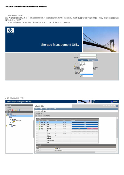
本文档的是从新建卷到将卷分配到服务器的配置过程截屏
1、访问MSA2012端IP。
由于A控制器管理口默认IP为10.0.0.2/255.255.255.0,B控制器为10.0.0.3/255.255.255.0,所以需要调整访问端IP为相同网段;同时,降低IE浏览器的安全级别(推荐为“中低”)
2、使用IE浏览器访问,输入IP地址,默认用户名为:manage,默认密码为:!manage
3登陆后的初始界面(下图)
4选中虚拟磁盘VD01单击右键选择创建卷
5这里我们可以调整你创建卷的大小,调整后点击应用,卷被成功创建。
6将创建好的卷映射到服务器中,选中刚刚创建好的卷,右键单击-设置-显式映射
7把VD001-V002的卷做给3号刀片服务器映射-选择BL680-03前的单选框-选择映射后面的复选框
8.LUN带星号为必填项,号码可随意填写,但不能与之前已用的LUN号相同- 访问后面可以选择访问权限,设置好后单击应用
9.映射成功
10.现在就可以进入3号刀片服务器的计算机管理看到显示映射过去的卷。


ASM设备中文资料ASM Teach流程一.设定及教读L/F二.设定及教读Mag.三.调整各部位的M/C data四.教读L/F Index五.教读Index PR六.教读Aligment七.Teach 1st PR及1st Backup PR八.Teach wire九.Teach Local lead (VLL)十.换针及金线十一.执行contact search 及reference parameter十二.执行Bond center十三.check各项参数( Bond、Base、Loop、Light、auto、funtion )十四.储存Date设定L/F Type data:一. 6 W/H Menu ?二. 0 W/H Setup ?三. 0 Change Device ?此项用以设定L/F的参数。
0 Device Name 可用以设定L/F的名称,机台最多支持8个字符的名称。
1 Number Scale 机台支持两种型态的单位表示:mil及mCM,其中mCM表示CM/10002 Number Of Unit 表示每条导线架上有多少个units。
3 Device Width 表示L/F的宽度。
4 Device Pitch 两个Device间的距离。
5 Rad to index hole 索引孔的半径。
6 Center Index hole 询问索引孔是否在两个Die Pad的中央位置。
7 Rail edge to index hole 表L/F边缘至索引端的距离。
L/F WIDTH教读一. 6 W/H MANU ?二. 0 W/H SETUP ?三. 2 LEARNING LF PARA ?四. 0 LEARN LF WIDTH ?步骤: 1.当进入时流道会做一次原点归值动作, 再回到原来未调整前宽度。
2.此时使用上、下键即可调整流道宽度。
3.完成调整后, 按STOP键跳出, 此时画面会SHOW出是否要UPDATE , 选择YES即OK。

Key Concepts for System Center 2012 – Operations ManagerMicrosoft CorporationPublished: November 1, 2013AuthorsSteve Moore and Byron RicksApplies ToSystem Center 2012 – Operations ManagerSystem Center 2012 Service Pack 1 (SP1) – Operations ManagerSystem Center 2012 R2 Operations ManagerFeedbackSend suggestions and comments about this document to ************************.CopyrightThis document is provided "as-is". Information and views expressed in this document, including URL and other Internet website references, may change without notice.Some examples depicted herein are provided for illustration only and are fictitious. No real association or connection is intended or should be inferred.This document does not provide you with any legal rights to any intellectual property in any Microsoft product. You may copy and use this document for your internal, reference purposes. You may modify this document for your internal, reference purposes.© 2013 Microsoft Corporation. All rights reserved.Microsoft, Active Directory, Bing, Internet Explorer, JScript, SharePoint, Silverlight, SQL Server, Visio, Visual Basic, Visual Studio, Win32, Windows, Windows Intune, Windows PowerShell, and Windows Vista are trademarks of the Microsoft group of companies. Portions of this documentation related to network monitoring are provided by EMC, and for those portions the following copyright notice applies 2010 © EMC Corporation. All rights reserved. All other trademarks are property of their respective owners.Revision HistoryContentsOperations Manager Key Concepts (4)Operations Manager Key ConceptsOperations Manager, a component of Microsoft System Center 2012, is software that helps you monitor services, devices, and operations for many computers from a single console. This topic explains basic concepts about Operations Manager for the administrator who manages the Operations Manager infrastructure and the operator who monitors and supports the computers in your business.What Operations Manager DoesBusinesses, small and large, are typically dependent on the services and applications provided by their computing environment. IT departments are responsible for ensuring the performance and availability of those critical services and applications. That means that IT departments need to know when there is a problem, identify where the problem is, and figure out what is causing the problem, ideally before the users of the applications encounter the problems. The more computers and devices in the business, the more challenging this task becomes.Using Operations Manager in the environment makes it easier to monitor multiple computers, devices, services, and applications. The Operations console, shown in the following image, enables you to check the health, performance, and availability for all monitored objects in the environment and helps you identify and resolve problems.To learn how to use the Operations Manager consoles, see Using the OperationsManager Consoles in the Operations Guide.Operations Manager will tell you which monitored objects are not healthy, send alerts when problems are identified, and provide information to help you identify the cause of a problem and possible solutions. As the administrator, you configure what will be monitored by selecting computers and devices to be monitored and importing management packs that providemonitoring for specific features and applications. To decide which objects to monitor and what to monitor for, you need to understand the features that comprise the Operations Manager infrastructure and how Operations Manager works.The Operations Manager InfrastructureInstalling Operations Manager creates a management group . The management group is the basic unit of functionality. At a minimum, a management group consists of a management server , the operational database , and the reporting data warehouse database. Note∙ The management server is the focal point for administering the management group and communicating with the database. When you open the Operations console and connect to a management group, you connect to a management server for that management group.Depending on the size of your computing environment, a management group can contain a single management server or multiple management servers.∙ The operational database is a SQL Server database that contains all configuration data for the management group and stores all monitoring data that is collected and processed for the management group. The operational database retains short-term data, by default 7 days.∙ The data warehouse database is a SQL Server database that stores monitoring and alerting data for historical purposes. Data that is written to the Operations Manager database is also written to the data warehouse database, so reports always contain current data. The data warehouse database retains long-term data.When Operations Manager reporting functionality is installed, the management group also contains a Reporting server which builds and presents reports from data in the data warehouse database.These core components of a management group can exist on a single server, or they can be distributed across multiple servers, as shown in the following image.For information about installing management group features, see Operations Manager 2012 Deployment Guide.Management ServersThe role of the management server is to administer the management group configuration, administer and communicate with agents, and communicate with the databases in the management group.The management group can contain multiple management servers to provide additional capacity and continuous availability. When two or more management servers are added to a management group, the management servers become part of a resource pool and work is spread across the members of the pool. When a member of the resource pool fails, other members in the resource pool will pick up that member’s workload. When a new management server is added, the new management server automatically picks up some of the work from existing members in theresource pool. All members in the resource pool will manage a distinct set of remote objects; at any given time, two members in the same pool will not manage the same object at the same time.A specialized type of management server is the gateway server. A gateway server enables the monitoring of computers in untrusted domains. For more information, see Monitoring Across Untrusted Boundaries.AgentsAn Operations Manager agent is a service that is installed on a computer. The agent collects data, compares sampled data to predefined values, creates alerts, and runs responses. A management server receives and distributes configurations to agents on monitored computers. Every agent reports to a management server in the management group. This management server is referred to as the agent's primary management server.Agents watch data sources on the monitored computer and collect information according to the configuration that is sent to it from its management server. The agent also calculates the health state of the monitored computer and objects on the monitored computer and reports back to the management server. When the health state of a monitored object changes or other criteria are met, an alert can be generated from the agent. This lets operators know that something requires attention. By providing health data about the monitored object to the management server, the agent provides an up-to-date picture of the health of the device and all the applications that it hosts.An agent can be configured to act as a proxy agent. A proxy agent is an agent that can forward data to a management server on behalf of a computer or network device other than its host computer. For example, an agent that is installed on the physical node of an SQL cluster can be enabled to act as proxy to monitor the cluster resource. Proxy agents enable monitoring of computers and devices on which an agent cannot be installed. For more information, see Agentless Monitoring.ServicesOn a monitored computer, the Operations Manager agent is listed as the System Center Management Health service. The System Center Management Health service collects performance data, executes tasks, and so on. Even when the service is unable to communicate with the management server it reports to, the service continues to run and queues the collected data and events on the disk of the monitored computer. When the connection is restored, the System Center Management Health service sends collected data and events to the management server.NoteThe System Center Management Health service is sometimes referred to as the healthservice.The System Center Management Health service also runs on management servers. On a management server, the System Center Management Health service runs monitoring workflowsand manages credentials. To run workflows, the System Center Management Health service initiates MonitoringHost.exe processes using specified credentials. These processes monitor and collect event log data, performance counter data, Windows Management Instrumentation (WMI) data, and run actions such as scripts.Management servers also run the System Center Data Access service and the System Center Management Configuration service.The System Center Data Access service provides access for the Operations console to the operational database and writes data to the database.The System Center Management Configuration service manages the relationships and topology of the management group. It also distributes management packs to monitored objects.Management PacksThe workflows that the System Center Management service runs are defined by management packs. Management packs define the information that the agent collects and returns to the management server for a specific application or technology. For example, the BizTalk Server Management Pack contains rules and monitors that collect and evaluate events and operations that are important to ensuring the health and efficiency of the BizTalk Server application.After Operations Manager installs an agent on a computer, it sends an initial configuration to the agent. The initial configuration includes object discoveries from management packs. The management pack defines the types of objects, such as applications and features, that will be monitored on computers that have been discovered by Operations Manager. Agents send data to the management server that identifies the instances of objects discovered on the computer. The management server then sends the agents the elements of management packs that apply to the discovered objects for each computer, such as rules and monitors.A rule defines the events and performance data to collect from computers and what to do with the information after it is collected. A simple way to think about rules is as an If/Then statement. For example, a management pack for an application might contain rules such as the following:∙ If a message indicating that the application is shutting down appears in the event log, create an alert.∙ If upload of a source file fails, collect the event that indicates this failure.As these examples show, rules can create alerts and collect events or performance data, which the agent sends to the management server. Rules can also run scripts, such as allowing a rule to attempt to restart a failed application.Discovered objects have a health state, which is reflected in the Operations console as green (successful or healthy), yellow (warning), or red (critical or unhealthy). Monitors define the health states for particular aspects of the monitored object. For example, a monitor for disk drive capacity might define green as less than 85 percent full, yellow as over 85 percent full, and red as over 90 percent full. A monitor can be configured to generate an alert when a state change occurs.How Objects Are Discovered and MonitoredThe following image is a simplified illustration of how objects are discovered and monitored.1. The administrator configures Operations Manager to search for computers to manage. Formore information about discovering computers, see Managing Discovery and Agents.2. Computers that meet the specified criteria and are not already managed are identified.3. An Operations Manager agent is installed on the discovered computer.4. The agent requests configuration data, and then the management server sends the agentconfiguration data from installed management packs that includes classes to be discovered.For example, if the Windows Server operating system management packs are installed, the management server will send the agent the operating system classes.5. The agent compares the configuration data to the computer, identifies any objects that itdiscovers, and returns the information to the management server. For example, the agent will return to the management server that an instance of Windows Server 2008 R2 operating system is on the computer.6. The management server sends the agent all monitoring logic from installed managementpacks that applies to the discovered objects. For example, the agent will receive allmonitoring logic that applies to Windows Server 2008 R2.7. The agent applies the monitoring logic, such as rules and monitors, runs workflows, andreturns data to the management server.8. As changes occur to discovered objects, such as applications being added or uninstalled, theagent sends the updated information to the management server, which then sends updated monitoring logic.NoteOperations Manager can also discover and monitor network devices, computers running UNIX and Linux operating systems, and provide agentless monitoring. For moreinformation, see Operations Manager Monitoring Scenarios in the Operations Guide.Communication Between Agents and Management ServersThe Operations Manager agent sends alert and discovery data to the primary management server, which writes the data to the operational database. The agent also sends events, performance, and state data to the primary management server for that agent, which writes the data to the operational and data warehouse databases simultaneously.The agent sends data according to the schedule parameters for each rule and monitor. For optimized collection rules, data is only transmitted if a sample of a counter differs from the previous sample by a specified tolerance, such as 10%. This helps reduce network traffic and the volume of data stored in the operational database.Additionally, all agents send a packet of data, called a heartbeat, to the management server on a regular schedule, by default every 60 seconds. The purpose of the heartbeat is to validate the availability of the agent and communication between the agent and the management server. For more information on heartbeats, see How Heartbeats Work in Operations Manager.For each agent, Operations Manager runs a health service watcher, which monitors the state of the remote Health Service from the perspective of the management server.Other resources for Operations Manager∙ TechNet Library main page for Operations Manager∙ To learn how to install Operations Manager and deploy a management group, see Deployment Guide for Operations Manager for System Center 2012∙ To learn how to use Operations Manager after the management group is set up, see Operations Guide for Operations Manager for System Center 2012∙ To learn how to create a management pack, see Author’s Guide for Operations Manager for System Center 2012∙ Operations Manager Documentation Downloads∙ Operations Manager Community。

ASM设备中文资料ASM Teach流程一.设定及教读L/F二.设定及教读Mag.三.调整各部位的M/C data四.教读L/F Index五.教读Index PR六.教读Aligment七.Teach 1st PR及1st Backup PR八.Teach wire九.Teach Local lead (VLL)十.换针及金线十一.执行contact search 及reference parameter十二.执行Bond center十三.check各项参数( Bond、Base、Loop、Light、auto、funtion )十四.储存Date设定L/F Type data:一. 6 W/H Menu ¿二. 0 W/H Setup ¿三. 0 Change Device ¿此项用以设定L/F的参数。
0 Device Name 可用以设定L/F的名称,机台最多支持8个字符的名称。
1 Number Scale 机台支持两种型态的单位表示:mil及mCM,其中mCM表示CM/10002 Number Of Unit 表示每条导线架上有多少个units。
3 Device Width 表示L/F的宽度。
4 Device Pitch 两个Device间的距离。
5 Rad to index hole 索引孔的半径。
6 Center Index hole 询问索引孔是否在两个Die Pad的中央位置。
7 Rail edge to index hole 表L/F边缘至索引端的距离。
L/F WIDTH教读一. 6 W/H MANU ¿二. 0 W/H SETUP ¿三. 2 LEARNING LF PARA ¿四. 0 LEARN LF WIDTH ¿步骤: 1.当进入时流道会做一次原点归值动作, 再回到原来未调整前宽度。
2.此时使用上、下键即可调整流道宽度。

System Center 2012 R2 Licensing DatasheetProduct OverviewMicrosoft System Center 2012 R2 offers solutions for managing datacenter resources, private clouds, and client devices.Private Cloud/Datacenter Management System Center 2012 R2 helps your organization achieve IT as a Service by enabling:∙Productive infrastructure: Deliver flexible, cost-effective private-cloud infrastructure to your business units in a self-service model, while carrying forwardyour existing data center investments.∙Predictable applications: Deep application insight combined with a “service-centric” approach helps you deliver predictable application-service levels.∙Cloud computing on your terms: Deliver and consume private and public cloud computing on your terms with common management experiences across your hybrid environments.Client ManagementSystem Center 2012 R2 helps IT empower people to use the devices and applications they need to be productive, while maintaining corporate compliance and control. Licensing OverviewSystem Center 2012 R2 is licensed by:∙License required only for endpoints being managed. No additional licenses are needed formanagement servers or SQL Server technology.∙Consistent licensing model across editions.Processor-based license, covering up to twoprocessors for server management. User- or OSE-based license for client management. Licensing Managed Servers System Center 2012 R2 server management licensing maximizes your private cloud value while simplifying purchasing. All server management licenses (SMLs) include the same components and the ability to manage any workload.System Center 2012 R2 SMLs will be released in two editions differentiated by virtualization rights only:∙Datacenter: Maximizes cloud capacity with unlimited virtualization for high density private clouds∙Standard: For lightly or non-virtualized private cloud workloads.Server ML Edition Comparison:separately.Determining the Number of Licenses NeededServer MLs are required for managed devices that run server Operating System Environments (OSEs). Licenses are processor-based, with each license covering up to two physical processors. The number of Server MLs required for each managed server is determined by the number of physical processor in the server for Datacenter Edition and either number of physical processors in the server or number of OSEs being managed for Standard Edition (whichever is greater). If you choose the Standard Server ML, you can add more licenses to a server to manage a greater number of virtual OSEs.Multiple System Center 2012 R2 Standard licenses may be assigned to the same server to license the number of managed OSEs. Components included in the Server MLs are not available separately.Flexibility to License Managed OSEs Running on Public Cloud PlatformsAll System Center 2012 R2 Server Management Licenses with active Software Assurance qualify for License Mobility through Software Assurance benefits. With the License Mobility through Software Assurance benefit, you can assign Server MLs to manage applications running on a public cloud infrastructure.For more information, see the Microsoft License Mobility through Software Assurance Customer Guide .Transitioning to the New Server Licensing ModelIf you have Software Assurance coverage on your current System Center licenses at the time of System Center 2012 R2 General Availability, you will receive the following System Center 2012 R2 Server ML grants listed below:You may migrate from System Center 2012 R2 Standard to System Center 2012 R2 Datacenter by purchasing a Step-Up License.Licensing Managed ClientsClient Management Licenses (MLs) are required for managed devices that run non-server OSEs. There are three System Center 2012 R2 Client ML offerings:Client MLs are available on a per-OSE or per-user basis. Components included in the Client MLs are not available separately.Transitioning to the New Client Licensing ModelIf you have Software Assurance coverage on your current System Center licenses at the time of System Center 2012 R2 General Availability, you will receive the following System Center 2012 R2 Client ML grants listed in the following table:Planning for System Center 2012 R2If you are planning to deploy System Center 2012 R2, either through upgrades or new licenses, please remember: ∙Renewing Software Assurance (SA) is the best way to protect investments and provide access to newversions as well as Deployment Planning Services and technical assistance.∙Select your edition of System Center 2012 R2 based on virtualization rights:o Datacenter Edition for highly virtualizedprivate clouds o Standard Edition for lightly or non-virtualizedprivate clouds∙Core CAL and Enterprise CAL Suites will continue to be the most cost effective way to purchase client management products.∙Find out how flexible payments can help you get the IT you need and stay on budget.Visit /financing for program details or to learn more. Or contact your Microsoft Solution Partner directly or by calling 1-800-936-3500 in the United States and Canada.Frequently Asked Questions (FAQ)System Center 2012 R2 Server ManagementQ: What's new in System Center 2012 R2 server management licensing?A: System Center 2012 R2 server management licensing does not change from System Center 2012. Q: Can you describe the product editions offered with System Center 2012 R2?A: Same as System Center 2012, System Center 2012 R2 server management licenses will be released in 2 editions differentiated by virtualization rights only:∙Datacenter: Maximizes cloud capacity with unlimited Operating System Environments (OSEs) for high density private clouds∙Standard: For lightly or non-virtualized private cloud workloads.There is no differentiation between the types of workloads you can manage with either edition. The only difference between the editions is the number of Operating System Environments (OSEs) that you can manage per license. Datacenter Edition allows the management of an unlimited number of OSEs per license. Standard Edition allows the management of up to two OSEs per license.Q: How do I determine the number of Server Management Licenses (MLs) I need?A: Server MLs are required for managed devices that run server OSEs. Licenses are processor-based, with each license covering up to two physical processors. The number of Server MLs required for each managed server is determined by the number of physical processors in the server for Datacenter Edition and either number of physical processors in the server or number of OSEs being managed for Standard Edition (whichever is greater).∙System Center 2012 R2 DatacenterEach license covers up to two physical processors, so you must count the number of physicalprocessors on the server, divide that number by two, round up to the nearest whole number,and acquire and assign that number of licenses to your server.Provided you acquire and assign to your server the required number of Datacenter editionserver management licenses, as described above, you may manage any number of OSEs onthat server.∙System Center 2012 R2 StandardFor each managed server count the number of physical processors and the number ofmanaged OSE's. You need the number of licenses to cover the greater number (processors orOSE's).device. In that case, you only count the number of virtual OSEs you will manage on the server, divide that number by two, and round up to the nearest whole number.Examples:*Multiple System Center 2012 R2 Standard licenses may be assigned to the same server to license the number of managed OSEs.Q: Can I purchase each of the System Center 2012 R2 Server Management License components separately?A: No. The System Center 2012 R2 Server Management components are part of an integrated offering to create and manage private cloud environments and are available only as part of System Center 2012 R2 Standard and System Center Datacenter MLs.Q: Can I split 2012 R2 Server MLs across multiple servers?A: No, a single Server ML may not be used to license two one-processor servers.Q: Can I assign more than one System Center 2012 R2 Standard license to the same server to increase the number of OSEs I may manage?A: Yes. The breakeven point for moving to SC 2012 R2 Datacenter is 7 VMs per host.Q: How much do the Server MLs cost?A: The Microsoft Volume Licensing Open License No Level (NL) U.S. Estimated Retail Price (ERP) is $1,323 for System Center 2012 R2 Standard and $3,607 for System Center 2012 R2 Datacenter. For your specific pricing, contact your Microsoft reseller. Actual prices may vary. Microsoft does not determine pricing or payment terms for licenses acquired through resellers.Q: Can I extend a Server ML to manage applications running on the public cloud?A: Yes, with the License Mobility through Software Assurance benefit, you can assign Server ML to manage applications running on a public cloud infrastructure. System Center 2012 R2 Standard licenses allow you to manage two virtual OSE in a public cloud, while System Center 2012 R2 Datacenter licenses allow you to manage up to eight virtual OSEs in a public cloud. When managing applications running on Azure, each Azure instance is considered to be one virtual OSE. For more information, see the Microsoft License Mobility through Software Assurance Customer Guide.。

gn2012a芯片手册引言:GN2012A芯片是一款具有高性能和低功耗特性的集成电路芯片。
它集成了多种功能,包括处理器、内存、通信接口和外设控制器等。
本手册的目的是介绍GN2012A芯片的硬件架构、功能、使用方法以及应用案例,以帮助用户更好地了解和使用该芯片。
一、芯片概述GN2012A芯片是一款基于ARM架构的处理器芯片,具有低功耗和高性能的特点。
它采用32位架构,频率高达1.5GHz,工作电压为1.2V,功耗低至几十mW,非常适合移动设备和嵌入式系统应用。
二、硬件架构GN2012A芯片采用了高度集成的设计,内部包含处理器核心、内存管理单元、外设控制器、通信接口等模块。
其中,处理器核心是芯片的核心部分,负责指令的执行和数据处理。
内存管理单元用于管理芯片内部的存储器,包括片上内存和外部存储器。
外设控制器提供了多种外设接口,如UART、SPI、I2C等,方便与外部设备进行通信。
通信接口包括以太网、WiFi、蓝牙等,为芯片提供了网络和无线连接的能力。
三、功能特性1.高性能:GN2012A芯片的主频高达1.5GHz,可提供强大的计算和处理能力。
2.低功耗:芯片采用先进的低功耗技术,功耗低至几十mW,延长了电池寿命。
3.多功能外设:芯片具备丰富的外设接口和通信接口,可连接多种外部设备和网络。
4.安全保护:芯片内部集成了安全保护机制,保护用户数据和系统安全。
5.多样化应用:GN2012A芯片适用于手机、平板电脑、智能家居等多种应用场景。
四、使用方法1.软件开发:开发者可以使用各种开发工具和软件包,如Keil、IAR等,进行软件开发。
开发过程中需要根据GN2012A芯片的指令集和寄存器操作手册进行编程。
2.硬件设计:设计者需要根据GN2012A芯片的硬件设计手册进行硬件设计,包括电路原理图、布线和仿真等环节。
3.软件调试:在软件开发完成后,可以使用调试工具进行软件调试,如JTAG调试器等。
通过调试可以发现和修复软件中的错误,确保软件的正常运行。

Microsoft Dynamics AX 2012 R3Pawel Kruk May 2014This document describes the typical steps for building Transportation management (TMS) engines and utilizing them in Microsoft Dynamics AX.Implementing anddeploying Transportation management enginesContentsImplementing and deploying Transportation management engines 3 Prerequisites 3 Architectural background 3 Tutorial: Construct a Hello-World rate engine 4 Tutorial: Enable a Hello-World rate engine 7 More about TMS engine implementation 8Implementing and deploying Transportation management enginesThe Transportation management (TMS) module includes a number of extension points that let you implement custom algorithms to perform tasks that are related to the rating of transport and freight reconciliation. The implementations of the algorithms are called Transportation management engines (also referred to as TMS engines or engines). The engines are delivered as implementations of specific .NET interfaces and deployed on the Microsoft Dynamics AX Application Object Server (AOS) tier. Each Transportation management engine can be switched on and off, and it can also be tuned at runtime, based on Microsoft Dynamics AX data. Some of the most important objectives of these engines are as follows:•Calculation of transportation rate•Calculation of travel distance from point to point•Calculation of the time it takes to travel from point to point•Zone identification of addresses•Distribution of transportation charges for shipments across source document lines (also referred to as apportionment of charges).Microsoft Dynamics AX 2012 R3 includes a number of fully functional engines that are available out of the box. However, in many cases, new engines might be required in order to satisfy contract requirements. For example, there is no engine that calculates freight charge by using a particular algorithm, or an engine might be required to retrieve rating data directly from a web service provided by the carrier.This document explains the typical steps for building Transportation management engines and utilizing them in Microsoft Dynamics AX. It is targeted to engineers who want to learn how to implement and deploy custom Transportation management engines.PrerequisitesMicrosoft Visual Studio Tools for Microsoft Dynamics AX must be installed. For more information, see/en-us/library/gg889157.aspx.Architectural backgroundThe following illustration shows a simplified view of the TMS system.Within TMS, a number of operations might require some kind of data processing that is specific to a particular carrier, such as transportation rate calculation. Typically, this kind of calculation requires a lot of input data, such as the origin and delivery addresses, the size, weight, and number of packages, and the requested delivery date. For a rate shopping operation, you can track this information from the Rate route workbench form. When you initiate a rate shoppingrequest, request XML is constructed in TMS by using one of the X++ classes that are derived from TMSProcessXML_Base. The request XML is passed to the processing system encapsulated in the .NET assembly named Microsoft.Dynamics.Ax.TMS (also referred to as the TMS managed system). The further processing involves instantiation and utilization of one or more Transportation management engines. The final response from the TMS managed system consists of XML, which is interpreted into a result that is persisted in the Microsoft Dynamics AX database.The source code of the TMS managed system is available in the Microsoft Dynamics AX Application Object Tree (AOT), under the following path: \Visual Studio Projects\C Sharp Projects\Microsoft.Dynamics.AX.Tms.All of the engines that are available out of the box in AX 2012 R3 are defined within the TMS managed system itself. We recommend that all custom engines be implemented in a stand-alone assembly. This assembly should be constructed by using Visual Studio Tools for Microsoft Dynamics AX, and its project should be hosted in the AOT. The Microsoft Dynamics AX server infrastructure ensures that the actual project output is deployed to a server-binary location upon AOS startup. Microsoft Dynamics AX models are the recommended vehicles for distributing the TMS engine implementations to customers. For more information about Microsoft Dynamics AX models, see/en-us/library/hh335184.aspx.Tutorial: Construct a Hello-World rate engineFollow these steps to implement a simple rate engine.1.Follow these steps to enable debugging and hot-swapping of assemblies on the Microsoft Dynamics AX server:1.Open the Microsoft Dynamics AX Server Configuration Utility.2.Create a new configuration.3.Select the Enable breakpoints to debug X++ code running on this server and Enable the hot-swapping ofassemblies for each development session check boxes.The following illustration shows the new configuration.4.Click OK to restart the AOS service.2.From the AOT, follow these steps to open the source of Microsoft.Dynamics.Ax.TMS in a new instance of VisualStudio:1.Navigate to \Visual Studio Projects\C Sharp Projects\Microsoft.Dynamics.AX.Tms.2.On the context menu, click Edit to open Visual Studio.3.Follow these steps to add a new C# Class Library project to the solution:1.In Solution Explorer, right-click your solution node, and then click Add > New Project.2.In the C# project templates, select Class Library.3.Enter HelloWorldEngines as the project name.4.Click OK.4.In Solution Explorer, right-click the HelloWorldEngines project node, and then click Add HelloWorldEngines to AOT.5.Follow these steps to add a project-to-project reference from your project to Microsoft.Dynamics.AX.Tms:1.In Solution Explorer, right-click the HelloWorldEngines project node, and then click Add Reference.2.On the Projects tab, select Microsoft.Dynamics.AX.Tms.3.Click OK.The following illustration shows what your solution should now look like in Solution Explorer.6.Follow these steps to enable deployment of the project output to the Microsoft Dynamics AX server:1.In Solution Explorer, select the project node.2.In the Properties window, set the Deploy to Server property to Yes.The following illustration shows the project properties after this change has been made.7.Follow these steps to implement a rate engine called HelloWorldRateEngine:1.In Solution Explorer, rename Class1.cs to HelloWorldRateEngine.cs.2.Implement the HelloWorldRateEngine class.The following example shows how to implement this class.namespace HelloWorldEngines{using System;using System.Xml.Linq;using Microsoft.Dynamics.Ax.Tms;using Microsoft.Dynamics.Ax.Tms.Bll;using Microsoft.Dynamics.Ax.Tms.Data;using Microsoft.Dynamics.Ax.Tms.Utility;/// <summary>///Sample rate engine class using rating formula of quantity * factor./// </summary>public class HelloWorldRateEngine : BaseRateEngine{private const string RATE_FACTOR = “RateFactor”;private decimal rateFactor;/// <summary>///Initializes the engine instance./// </summary>/// <param name=”rateEngine”>Rate engine setup record.</param>/// <param name=”ratingDto”>Rating data transfer object.</param>public override void Initialize(TMSRateEngine rateEngine,RatingDto ratingDto){base.Initialize(rateEngine, ratingDto);RateEngineParameters parameters =new RateEngineParameters(TMSEngine.RateEngine,rateEngine.RateEngineCode);// Try to retrieve decimal value of RateFactor parameter specified// on engine setup Parametersif (!Decimal.TryParse(parameters.RetrieveStringValue(RATE_FACTOR),out rateFactor)){// Throw TMS Exception. The exception message is shown in infolog.// Additional exception data is recorded in// “Transportation system error log”throw TMSException.Create(“HelloWorldRateEngine requires definition of RateFactor parameter with valid decimal value”,TMSExceptionType.TMSEngineSetupException);}}/// <summary>///Calculates rate./// </summary>/// <param name=”transactionFacade”>The request transaction facade.</param>/// <param name=”shipment”>Rated shipment element.</param>/// <param name=”rateMasterCode”>Rate master code.</param>/// <returns>Updated rating data transfer object.</returns>public override RatingDto Rate(TransactionFacade transactionFacade,XElement shipment,string rateMasterCode){// Use extension method to sum down the item// quantity from the shipment XML elementdecimal quantity = shipment.SumDown(ElementXmlConstants.Quantity);// Retrieve or create rating elementXElement rateEntity = shipment.RetrieveOrCreateRatingEntity(this.RatingDto);// Use extension method to record rate// This method does not record additional information// like unit counts, currency etc.rateEntity.AddRate(TmsRateType.Rate, quantity * rateFactor);return this.RatingDto;}}}8.In Solution Explorer, select the HelloWorldEngines project node, and then click Add HelloWorldEngines to AOT.9.Follow these steps to deploy the engine assembly:1.In Solution Explorer, right-click your project node, and then click Deploy.2.Restart AOS.Your engine assembly is now available for use in Microsoft Dynamics AX. You can verify that HelloWorldEngines.dll is available in the following folder: [AOS installation location]\bin\VSAssemblies.Tutorial: Enable a Hello-World rate engineFollow these steps to enable the engine that you implemented and deployed in the previous tutorial.1.Follow these steps to create a rating engine in Microsoft Dynamics AX:1.Click Transportation Management > Setup > Engines > Rate engine to open the Rate engine form.2.Create a new record that refers to the engine that you created in step 4 of the previous tutorial:•Rate engine: HelloWorld•Name: Hello World Rate Engine•Engine assembly: HelloWorldEngines.dll•Engine type: HelloWorldEngines.HelloWorldRateEngineThe following illustration shows the new record.Note: Because your engine does not source any data from Microsoft Dynamics AX, you don’t need to construct andassign a rate base type for it.2.Follow these steps to specify a value for the RateFactor parameter:1.In the Rate engine form, click Parameters.2.Create a parameter record for RateFactor, and assign a value of3.Your engine is now ready for use.To test the engine, assign it to the rating profile of an active carrier, and run the rating, based on a source document that includes at least one line with a specific quantity. The total rate is computed as (Total lines quantity) * (RateFactor value). The Hello-World engine implementation is not currency-sensitive.For more information about how to associate shipping carriers with rate engines, see Set up shipping carriers and carrier groups.More about TMS engine implementation•Extension types– The following table enumerates the most important interfaces and abstract classes for building engine extensions. All these base types are defined in the Microsoft.Dynamics.Ax.Tms.Bll namespace.•User messages– To format a language-specific user message, use the Microsoft.Dynamics.Ax.Tms.TMSGlobal class that is defined in the TMS managed system. This class contains an overloaded method, called getLabel, that lets you retrieve a Microsoft Dynamics AX label in the current user language.•Language-sensitive data– The input and output XML can contain elements that carry language-sensitive data, such as dates or decimal numbers. The TMS managed system enforces that the current language of the thread is set to invariant. Use System.Globalization.CultureInfo.CurrentCulture to serialize and de-serialize XML data. •Accessing data from Microsoft Dynamics AX– A rate engine might require read or write access to the Microsoft Dynamics AX database. We highly recommend that you use proxy classes for .NET interop for interaction with tables in Microsoft Dynamics AX. For more information about proxy classes, see /en-us/library/gg879799.aspx.If you use proxy classes to interact with the Microsoft Dynamics AX database, consider using LINQ to Microsoft Dynamics AX to build and run queries. For more information about LINQ to Microsoft Dynamics AX, see/en-us/library/jj677293.aspx.Out of the box, the TMS managed system provides access to interaction with some of the TMS-specific tables by using proxy classes for .NET interop and LINQ to Microsoft Dynamics AX. You can use theMicrosoft.Dynamics.Ax.Tms.Data.AXDataRepository class to retrieve IQueryable objects for these tables.•Using the common engine data infrastructure– All the engines that are shipped out of the box with AX 2012 R3 require Microsoft Dynamics AX data in order to do the actual calculations. To reduce the cost of building engines that must source data from Microsoft Dynamics AX, the TMS system includes an implementation of a common engine data infrastructure. This feature enables the recording of engine-specific data, without the need to add new Microsoft Dynamics AX tables and build additional Microsoft Dynamics AX forms to maintain data. For more information about how to set up engine metadata, see “Transportation management engines” and “Set uptransportation management engines” under Rating setup in online Help.The TMS system defines a number of tables and Microsoft Dynamics AX forms that enable the recording of engine-specific data. This data is stored in physical table records that contain a number of generic table fields that can be reused for different purposes, depending on the specific engine implementation. For proper UI interpretation of data at runtime, metadata is recorded. For each group of data records that are used by a particular engine, a number of metadata records are required. These metadata records describe the caption, data type, lookup type, and a few other properties for each generic field that the engine is using.Use the following table to find the Microsoft Dynamics AX table that contains data and metadata for a particular type of engine.Send feedback.Microsoft Dynamics is a line of integrated, adaptable business management solutions that enables you and your people to make business decisions with greater confidence. Microsoft Dynamics works like and with familiar Microsoft software, automating and streamlining financial, customer relationship, and supply chain processes in a way that helps you drive business success. United States and Canada toll free: (888) 477-7989Worldwide: (1) (701) 281-6500/dynamics。

此次配置过程,只针对最基础的使用要求(单机直连)。
且此次配制流程大体遵照RoadMap手册进行。
1.对于大多数用户来说,SMU是配置MSA2000产品的第一选择,所以在配置前首先设置本机的IE浏览器:a)浏览器为IE5.5、FireFox1.0.7或者以上版本b)允许窗口弹出c)允许动态显示d)调整浏览器的安全级别,cookie权限2.配置本机IP地址,要与MSA2000的IP为同一网段,且子网掩码相同。
a)在存储为双控制器,且网络环境中没有DHCP服务器情况下:当前MSA2012fc的A控制器IP地址为10.0.0.2,B控制器IP地址为10.0.0.3,子网掩码为255.255.255.0,当前网关为10.0.0.1。
b)如果此时将控制器直接接入含有DHCP服务器的网络,此时可以在本机使用串口线采用CLICommand方式使用命令show network-parameters来确认控制器的IP地址。
默认情况下,初始具有管理权限登陆SMU的帐户用户名为manage 密码:!manage3.设置MSA2012fc的系统时间和日期,务必执行该操作的原因在于Event Log中使用的时间为本机时间,如果不进行时间校准,则很难根据Log判断问题。
执行路径:Manage > General Config > Set Date/Time4.设置host ports模式。
由于对于host ports的设置会影响到Virtual Disk,所以首先需要进行此项配置。
执行路径:Manage > General Config > Host Port Configurationa)蓝色阴影部分指示port在控制器上的位置b)光纤传输速率(Link Speed):2GBit/Second和4GBit/Second。
这一选项的设置一定要和HBA的速率匹配。
如果此选项中有所修改,需要点击Update Host Port Configuration进行保存c)该port目前所处的topology模式:默认情况下host post的topology的模式为loopNOTE:下述3个选项需要根据用户现场环境要求进行变更和修改。

Windows System Center 2012全接触合理安装System Center套件至少需要九台独立的服务器/虚拟机,至少还需要总共32GB的内存。
System Center套件的许可成本决定了部署Windows Server数据中心版的公司使用该套件才有意义。
【51CTO精选译文】想把微软的System Center产品套件归为某一组产品可不容易。
System Center涵盖众多不同的组件,想通过单单一篇文章来评述System Center的所有组件多少有点难度。
System Center 2012已经部署在生产环境中--服务包1(SP1)也为期不远了。
微软的一大堆互不匹配的"System Center"服务器正慢慢结合起来,组成一款无可匹敌的企业级解决方案。
System Center套件共同提供了一个软件架构,应该会让从Solar Winds、PuppetLabs到VMware的每家厂商寝食难安。
惠普、IBM及高端企业软件领域的其他厂商也会有所注意。
System Center 2012是整个套件中没有哪个组件存在某个过于明显的缺点的头一个版本。
微软还大大简化了许可模式,为该软件包敲定了颇具竞争力的价格,旨在抢占高利润市场的大部分份额。
System Center 2012所定的价格不太适合一定规模以下的企业组织,但微软喜欢这样子。
该公司对中小企业市场采取了一项全然不同的战略,该战略不大注重本地IT,而是更注重云订购模式。
System Center 2012里面有啥名堂System Center顾问System Center顾问(SCA)也许是System Center中最不为人所知的组件。
摆明使用SCA的理由有点难度。
SCA是一项云服务,可以分析你部署的基础设施,寻找存在的问题。
眼下,它还不是那么复杂;它就好比是各种微软最佳实践分析器(Microsoft Best Practices Analyzers)的云版本,但是能够跟踪整个数据中心的历史情况。

IRS20124S中文资料D IGIT AL A UDIO D RIVER WITH D ISCRETE D EAD -TIME AND P ROTECTIONProduct SummaryV SUPPL Y 200V max.I O +/-1A / 1.2A typ.Selectable Dead Time15/25/35/45ns typ.Prop Delay Time 70ns typ.Bi-directional Over Current SensingFeatures200V high voltage ratings deliver up to 1000Woutput power in Class D audio amplifier applicationsIntegrated dead-time generation and bi-directional over current sensing simplify designProgrammable compensated preset dead-time for improved THD performances over temperature ?High noise immunity Shutdown function protects devices from overload conditionsIRS20124S(PbF)SymbolDefinitionMin.Max.UnitsV B High side floating supply voltage -0.3220V V s High side floating supply voltage VB-20VB+0.3V V HO High side floating output voltage Vs-0.3VB+0.3V V CC Low side fixed supply voltage -0.320V V LO Low side output voltage -0.3Vcc+0.3V V INInput voltage-0.3Vcc+0.3V V OC OC pin input voltage-0.3Vcc+0.3V V OCSET1 OCSET1 pin input voltage -0.3Vcc+0.3V V OCSET2OCSET2 pin input voltage-0.3Vcc+0.3V dVs/dt Allowable Vs voltage slew rate-50V/ns Pd Maximum power dissipation- 1.25W Rth JA Thermal resistance, Junction to ambient -100°C/W T J Junctio n Temperature -150°C T S Storage Temperature-55150°CT LLead temperature (Soldering, 10 seconds)-300°CAbsolute Maximum RatingsAbsolute maximum ratings indicate sustained limits beyond which damage to the device may occur. All voltage parameters are absolute voltages referenced to COM. All currents are defined positive into any lead. The thermal resistance and power dissipation ratings are measured under board mounted and still air conditions.DescriptionThe IRS20124S is a high voltage, high speed power MOSFET driver with internal dead-time and shutdown functions specially designed for Class D audio amplifier applications.The internal dead time generation block provides accurate gate switch timing and enables tight dead-time settings for better THD performances.In order to maximize other audio performance characteristics,all switching times are designed for immunity from external disturbances such as VCC perturbation and incoming switching noise on the DT pin. Logic inputs are compatible with LSTTL output or standard CMOS down to 3.0V without speed degradation. The output drivers feature high current buffers capable of sourcing 1.0A and sinking 1.2A. Internal delays are optimized to achieve minimal dead-time variations. Proprietary HVIC and latch immune CMOS technologies guarantee operation down to Vs= –4V, providing outstanding capabilities of latch and surge immunities with rugged monolithic construction.Recommended Operating ConditionsFor Proper operation, the device should be used within the recommended conditions. The Vs and COM offset ratings are tested with all supplies biased at 15V differential.Symbol Definition Min.Max.Units V B High side floating supply absolute voltage Vs+10Vs+18V V S High side floating supply offset voltage Note 1200VV V HO High side floating output voltage Vs VB V CC Low side fixed supply voltage1018V V LO Low side output voltage0VCC V V IN Logic input voltage0VCC V V OC OC pin input voltage0VCC V V OCSET1OCSET1 pin input voltage0VCC V V OCSET2OCSET2 pin input voltage0VCC V T A Ambient Temperature-40125°CDynamic Electrical CharacteristicsV BIAS (V CC, V BS) = 15V, C L = 1nF and T A = 25°C unless otherwise specified. Figure 2 shows the timing definitions.IRS20124S(PbF)Lead DefinitionsSymbol DescriptionVCC Low side logic Supply voltage VB High side floating supply HO High side outputVS High side floating supply returnINLogic input for high and low side gate driver outputs (HO and LO), in phase with HODT/SD Input for programmable dead-time, referenced to COM. Shutdown LO and HO when tied to COM COM Low side supply returnLO Low side outputOC Over current output (negative logic)OC SET1Input for setting negative over current threshold OC SET2Input for setting positive over current thresholdIRS20124S(PbF)VBHOVSO O C S E T O C S E T VccLOCOM50%50%t off(L)t on(L)90%10%90%10%DT HO-LOt off(H)INHOLOt on(H)DT LO-HO DT/SDHO LOV SDT SD90%Figure 1. Switching Time Waveform Definitions Figure 2. Shutdown Waveform Definitions IRS20124S(PbF)toc filt HIGHVSOCV soct COMCOMtwocVSOCV Soc+tdocCOM COMLOV Soc-15V Vsoc+Vsoc-OCVsoc+Vsoc-COM VSOCFigure 5. OC Waveform DefinitionsFigure 3. OC Input FilterTime Definitions IRS20124S(PbF)IRS20124S(PbF)2.0()2()IRS20124S(PbF)2430()()IRS20124S(PbF)10()10()IRS20124S(PbF)。

Step by step installation of SCOM 2012Pre-Install Preparation1.Ensure that all minimum requirements are met for the role(s) you areinstalling. The list of requirements for each role can be found here. 2.Ensure that the account being used to run your Management Serverservices is a member of the Local Administrators group on each ofyour Management Server.3.Ensure that any machine that is going to run the Operations Consolehas the MS Report Viewer installed, which can be found here.4.Ensure that the DW Write account for the environment you areinstalling is a local Administrator on the server hosting the SSRSReporting installation that will be used for SCOM.Install the First Agent Management ServerLog on to the server by using an account that has local administrative credentials.1.On the Operations Manager installation media, run Setup.exe, andthen on the splash screen click Install.2.On the Getting Started, Select features to install page, select theManagement server feature, and then click Next.3.On the Getting Started, Select installation location page, accept thedefault value of C:\Program Files\System Center 2012\Operations Manager. Or, type a new location or browse to one, and then clickNext.4.On the Prerequisites page, review and resolve any warnings or errors,and then click Verify Prerequisites Again to recheck the system.5.If the Prerequisites checker does not return any warnings or errors,the Prerequisites, Proceed with Setup page appears. Click Next.6.On the Configuration, Specify an installation option page, selectCreate the first Management server in a new management group, type the name for the management group, and then click Next.7.On the Configuration, Please read the license terms page, reviewthe Microsoft Software License Terms, select I have read,understood and agree with the license terms, and then click Next.8.When the Configuration, Configure the operational database pageopens, in the Server name and instance name box, type the name of the server and the name of the SQL Server instance for the database server that will host the operational database.9.After you type the correct value for the SQL Server database servername, click the SQL Server port box so that Setup will attempt to validate the values you typed for the SQL Server name and for the port number. If validation fails, ensure the SQL instance name you typed in is correct, and that you have permissions to read from the Master database and create new databases on the specified SQL instance, and try again.10.In the Database name, Database size (MB), Data file folder, andLog file folder boxes, accept the default values, and click Next. 11.When the Configuration, Configure the data warehouse databasepage opens, in the Server name and instance name box, type the server name and the name of the instance of SQL Server for thedatabase server that will host the data warehouse database.12.Because this is the first management server installation, accept thedefault value of Create a new data warehouse database.13.In the Database name, Database size (MB), Data file folder, andLog file folder boxes, accept the default values, and click Next. 14.On the Configuration, Configure Operations Manager accountspage, ensure that the Domain Account option is selected for each of the Management server action account, the System CenterConfiguration service and System Center Data Access serviceaccount, the Data Reader account, and the Data Writer account rows. Enter in the appropriate usernames for each row, with allpasswords. Click Next when finished.15.On the Configuration, Help improve System Center 2012 –Operations Manager page, select Yes for both options, and then click Next.16.Review the options on the Configuration, Installation Summarypage, and then click Install. Setup continues.17.When Setup is finished, the Setup is complete page appears. ClickClose.BeginningsThe following step-by-step walkthrough, starts from a newly built Microsoft Windows 2008R2 with SP1 Enterprise member server. We already have a fully working SQL Server 2008 R2 instance on a different member server.Database requirements:· SQL Collation: IMPORTANT - install SCOM 2012 on SQL withthe SQL_Latin1_General_CP1_CI_AS collation!·SQL Server 2008 with SP1/2/3, 2008R2, or 2008 R2 SP1 - Standard or Enterprise editions (no support for Express editions - it will not work, trust me, I’ve tried it!)· SQL Server Agent service must be started, and the startup type must be set to automatic· The db_owner role for the operational database must be a domain account· SQL Server Full Text Search is required· SQL Services Reporting Services (for Operations Manager Reporting)Note: If you don’t yet have an SQL Server 2008 R2 instance, a standard Next Next Next type install with Full Text Search, will suffice for the following demo/pilot.WalkthroughPart 1 - Server PreparationLogged in as a domain user with local administrator permissions (using domain administrator here which is not best practice)Add Features Wizard: Install the .NET Framework 3.5.1 feature from Server Manager > Features > Add Features:Accept to add the additional Required Role Services and Next > Next >:Select the role services to install for Web Server (IIS): Add the following IIS role services and Next >:· IIS6 Metabase Compatability· (and accept Add Required Role Services which includes the required - Default Document, ISAPI Filters, and ISAPI Extensions)· Windows Authentication· Static Content· Directory Browsing· HTTP Errors· HTTP Logging· Request Monitor· Static Content Compression· IIS Management Console· CGIConfirm Installation Selections: and Install:Download and install Microsoft .NET Framework 4 (Web Installer): dotNetFx40_Full_setup.exeInternet Information Services (IIS) Manager: From IIS Manager > Select the Web Server object > ISAPI and CGI Restrictions icon> and make sure that v4 is Allowed for 32 and 64 bit:Download and install the Report Viewer controls which are part of the Microsoft Report Viewer 2010 Redistributable Package: ReportViewer.exe(Optional) Turn off Windows Firewall:Mount the SQL Server 2008 R2 DVD/ISO:en_sql_server_2008_r2_enterprise_x86_x64_ia64_dvd_520517.isoAnd run through the ‘New installation or add features to an existing installation’ wizard to install ‘Reporting Services’:Note: We use a remote database for the operational database, and data warehouse database; installing Reporting Services here serves to populate the SQL Server instance field when on the ‘S QL Server instance for reporting services step’ of the SCOM2012 installation (see here for more info.) The SSRS instance needs to be a separate instance to SQL instance used by SCOM.At this stage it would be worth updating the server with the latest Microsoft and Windows patches.Part 2 - SCOM 2012 InstallInsert the System Center 2012 Operations Manager DVD/ISO and run SETUP.EXE (if autorun disabled):en_system_center_2012_operations_manager_x86_x64_dvd_804695.isoThe Microsoft System Center 2012 - Operations Manager setup screen appears:Links for reference:Release NotesInstallation GuidanceSupported ConfigurationsProduct DocumentationOperations Manager CommunityClick the Install button:Select features to install (here we’re going for a complete install) and Next >:Select installation location and Next >:Verify Prerequisites and if okay then Next >:Specify whether this is going to be the first Management server or an additional one (here we are creating a first one, so we need to provide a Management group name) and Next >:Accept the license terms and Next >:Configure the operational database - provide name and instance name of the SQL server to be used, configure further as required, and Next >:Configure the data warehouse database as required and Next >:SQL Server instance for reporting services - since we installed SSRS locally, this will pick up the local instance, Next >:Specify a web site for use with the Web console - use ‘Default Web Site’ or select as required, Next >:Select an authentication mode for use with the Web console, Next >:Configure Operations Manage accounts (for the demo using the domain administrator account which is not best practice - see Operations Manager Security Guide), Next >:Customer Experience Improvement and other stuff, Next> :Microsoft Update setting, Next >:Installation Summary, Install:The End!Note: In hindsight; for a demo you could probably get away with a local installation SQL Standard or Enterprise on the SCOM Server, with an additional instance for Reporting Services. Apologies I have no time to verify this.。


目录第一章安装说明 (12)1.1系统要求 (12)1.1.1数据库服务器系统要求 (12)1。
1.2W EB服务器系统要求 (12)1.2系统安装部署 (12)1。
2.1CREC项目综合管理信息平台数据库系统安装 (12)1.2.2CREC项目综合管理信息平台安装 (16)1。
2。
3CREC项目综合管理信息平台卸载 (21)第二章操作说明 (22)2。
1.界面布局 (22)2.2.操作按钮说明 (23)2.3.查询区域说明 (23)2.4流程 (24)第三章系统管理 (25)3.1用户权限管理 (25)3.1.1组织机构管理 (25)3。
1。
2用户管理 (26)3.1。
3用户参与组织机构管理 (27)3.1.4角色管理 (28)3.1.5角色权限分配 (29)3。
1。
6用户隶属角色 (30)3。
1.7重置密码 (31)3.1。
8日志查询 (32)3.2我的工作 (32)3。
2.1修改密码 (32)3.2.2待办工作 (32)3。
2.3督办工作 (33)3。
3工作流管理 (34)3。
3.1定义工作流 (34)3。
3.2工作流导出 (41)3。
3。
3工作流复制 (42)第四章合同管理 (46)4。
1总包合同 (46)4。
2总包合同评审 (46)4.3总包合同变更 (47)4.4总包合同统计 (48)第五章项目基本信息管理 (49)5。
1项目基本信息 (49)5。
2项目基本信息查询 (49)5。
3项目作业队 (49)5.4作业队参与成本工作分解 (49)5。
5招投标信息 (49)第六章成本管理 (50)6.1成本工作分解 (50)6.2成本计划编制 (51)6.3大宗料备料计划 (54)6。
4其他材料备料计划 (55)6.5对内验工 (57)6.6对内验工统计 (59)6.7对外验工 (59)6.8对外验工统计 (59)6.9全部成本计划汇总 (59)6.10已审核成本计划汇总 (59)6.11未审核成本计划汇总 (59)6.12其他费用管理 (59)6.13设计工程量变更记录 (60)第七章物资管理 (61)7。

Hunan University. P. R. China Hunan University. P. R. Chinapunctuation marks, and other symbols.Hunan University. P. R. China Xujing Yang Hunan University. P. R. China Xujing YangModes of NC SystemsHunan University. P. R. China Xujing Yang Hunan University. P. R. China Xujing YangServo Drive Control ModesClosed-Loop System with Feedback统的闭环控制系统)•半闭环系统•全闭环系统Hunan University. P. R. ChinaXujing YangNumerical Control Hunan University. P. R. ChinaXujing YangRS232CRS422Data Server/IC CardHunan University. P. R. China Xujing Yang Hunan University. P. R. ChinaLimitations of CNCHigh initial investment (初始投资大)Hunan University. P. R. China Hunan University. P. R. ChinaHunan University. P. R. China Hunan University. P. R. China Vertical CNC MachinesHunan University. P. R. China Hunan University. P. R. ChinaHunan University. P. R. China Hunan University. P. R. ChinaHunan University. P. R. China Xujing Yang Hunan University. P. R. ChinaHunan University. P. R. China Hunan University. P. R. China Classical Portal Milling Machine from Zimmermann Boko Ltd. (Germany)Hunan University. P. R. China Xujing Yang Hunan University. P. R. ChinaHunan University. P. R. China Hunan University. P. R. China Xujing YangMachinesHunan University. P. R. ChinaXujing YangMachinesUniversityHunan University. P. R. ChinaXujing Yang多轴加工中心复合加工中心Other Technologies forCNC Machines 横梁移动式多轴加工中心Hunan University. P. R. ChinaXujing Yang变速齿轮传动Hunan University. P. R. China同步齿形带传动主轴电机直接驱动(电主轴)Spindle 主轴电机支承丝杠螺母伺服进给系统Hunan University. P. R. ChinaXujing Yang床身Hunan University. P. R. China数控回转工作台、数控分度工作台You CAN do it well!Hunan University. P. R. China Hunan University. P. R. China Xujing YangHunan University. P. R. China Xujing Yang Hunan University. P. R. ChinaHunan University. P. R. China±30°/ 220°/mmX, Y, U, V, Zaxes350 x 220mm350 x 220 x 220mmHunan University. P. R. ChinaWelding MachinesRobot MachiningHunan University. P. R. China Xujing Yang Hunan University. P. R. ChinaRobot Examples。


T E C H N O L O G YR E F E R E N C EG U I D E2012CIVIC SEDAN w w w.o w n e r s.h o n d a.c o mEX,EX-L,Si,and GXiPod ®or USB Flash Drive (14)Bluetooth ®Audio (15)Owner Link..............................................................................................................16Safety Reminder......................................................................................................17Fuel Recommendation. (17)ECONBUTTON p.6BLUETOOTH ®HANDSFREELINK ®p.10INSTRUMENT PANEL p.4MID p.8AUDIO p.14p.10Programmable Auto Door SettingsAUTO DOOR UNLOCKWhen you turn the ignition OFF When you shift into ParkWhen you turn the ignition OFF When you shift into ParkOperate manuallyAUTO DOOR LOCKWhen you reach 10mph When you shift out of ParkOperate manuallyPress MENU.Select Customize Settings.Select Door Setup.Select Auto Door Unlock.Select All Doors with Shift Press MENU to exit.Malfunction IndicatorsIf an indicator remains on,there may be a problem;see your dealerOn/Off IndicatorsOFF display)1st detent:parking 2nd detent:headlights Charging systemLow brake fluid,Brake system oil pressureABS (anti-lock brake system)(supplemental restraint system)EPS (electric power steering)ransmission (blinking)(automatic transmission)Low fuel:RefillLow tire pressure:Add airHigh temperature:Drive slowly or pull overImmobilizerFlashes:improperly use correct keySi onlyi-VTEC indicatorSi onlyREV indicatorsMessage indicator:See MIDWhat to Do3.Check the multi-information display for the system status.Press ECON again to turn system off.AMBIENT mphmphmphHigh fuel efficiencyModerate fuel efficiencyLow fuel efficiencyWhenPress the SEL/RESET buttonto change sub-displays.Press the INFO button to changemain displays.Button: wallpaper)Display/InformationPick-Up button: Answer an incoming call, or godirectly to the Phone screen.Use these two buttons to navigate through the HFL menus. Audio selector knob:Back button: Press toprompt appears. Select Y es.2. Make sure your phone is indiscovery mode. Select OK.to HFL. Go3. HFL searches for your phone.Select it when it appears onthe screen. Go to step 4.4. HFL gives you a four-digit code.Enter it on your phone whenprompted. Select OK to complete.NOTE:T o pair another phone to HFL (or if the prompts do not appear), you must use the Phone Setup menu. See your Owner’s Manual for pairing instructions.Receiving a Callend or decline the call.go to the Phone screen.2. Select Dial.information display.2. Press the Pick-Up button to accept the call.press the Pick-Up button to call.4. The call is connected and heard through the vehicle speakers.4. The call is connected and heard through the vehicle speakers.2. Select Phonebook.to go to the Phone screen.Speed Dial* When a voice tag is stored for a speed dial entry,you can make a call using voice commands.See your Owner’s Manual for instructions.4. The call is connected and heardthrough the vehicle speakers.2. Select Speed Dial.to go to the Phone screen.want to call, and select it.select it.Press “play” on your phone; sound is redirected to the audio system.3. Press SOURCE or AUX until iPod or USB mode appears. Audio begins to play.2. Connect the USB connector to your iPod dock connector or flash drive.。

2012server序列号2012年的服务器序列号是一串唯一标识符,它代表了一个特定的服务器。
这个序列号可以用来识别服务器的身份和功能。
它类似于人类的身份证号码,可以帮助服务器在网络中定位和辨识。
每个服务器都有一个独一无二的序列号,这个序列号由一串数字和字母组成。
它不仅可以用于服务器的管理和维护,也可以用于监控和诊断服务器的运行状态。
服务器序列号的重要性不言而喻,它是服务器的身份象征,也是服务器运行的保证。
服务器序列号的生成是一个复杂的过程,涉及到多个因素和参数。
它通常由服务器的制造商或供应商根据一定的算法生成。
这个算法是保密的,只有制造商或供应商才知道。
每个制造商或供应商都有自己的算法,因此每个服务器序列号都是唯一的。
服务器序列号的重要性在于它可以帮助服务器在网络中被识别和定位。
当一个服务器发送请求或接收数据时,它可以通过序列号来区分自己和其他服务器。
这样就可以确保数据的准确传输和处理。
服务器序列号还可以用于服务器的管理和维护。
管理员可以通过序列号来监控服务器的运行状态和性能,及时发现和解决问题。
除了用于服务器的管理和维护,服务器序列号还可以用于服务器的安全性。
通过序列号,管理员可以对服务器进行身份验证,确保只有授权的人员才能访问服务器的敏感信息和功能。
这样可以有效防止未经授权的人员对服务器进行恶意攻击或滥用。
2012年的服务器序列号是服务器的独特标识符,它可以帮助服务器在网络中被识别和定位,确保数据的准确传输和处理。
它还可以用于服务器的管理和维护,以及服务器的安全性。
服务器序列号的重要性不可忽视,它是服务器运行的保证和安全的基石。
A PLUS MAKE YOUR PRODUCTION A-PLUSA SM2012CBDATA SHEETA PLUS INTEGRATED CIRCUITS INC.Address:3 F-10, No. 32, Sec. 1, Chenggung Rd., Taipei, Taiwan 115, R.O.C.(115)台北市南港區成功路㆒段32號3樓之10. TEL: 886-2-2782-9266FAX: 886-2-2782-9255WEBSITE : http: // Sales E-mail: Mr. Jasonsales@Technology E-mail: Mr. George service@ASM2012CB – VERY LOW-COST VOICE SYNTHESIZER WITH 4-BIT MICROPROCESSOR1.0 General DescriptionThe AM4DD0207 is very low cost voice synthesizer with 4-bit microprocessor. It has various features including 4-bit ALU, ROM, RAM, I/O ports, timers, clock generator, watchdog timer(WDT), voice synthesizer, etc. It consists of 22 instructions in the device. With CMOS technology and halt function can minimize power dissipation. Its architecture is similar to RISC, with two stages of instruction pipeline. It allows all instructions to be executed in a single cycle, except for program branches and data table read instructions (which need two instruction cycles).1.1 FeatureSingle power supply can operate from 2.4V through 5VInternal Program ROM: 4K x 10-bit1 sets of 16-bit DPR can access up to 64K x 10 bits data memory spaceData Registers:•96 x 4-bit data RAM (00-1Fh plus 40h-7Fh)•Unbanked special function registers (SFR) range: 20h-3FhI/O Ports:•PRA: 4-bit I/O Port A (2Bh)•PRB: 4-bit Output Port B (2Dh)•PRC: 4-bit Input Port C (2Fh)On-chip clock generator: Resistive Clock Drive(RM)Timer: 1•Timer0: a 9-bit auto-reload timer/counterStack: 2-level subroutine nestingHALT and Release from HALT function to reduce power consumptionWatch Dog Timer (WDT)Instruction: 1-cycle instruction except for table read and program branches which are 2-cycles Number of instruction: 22The Voice function can be implemented by microprocessor instruction• One 8-bit COUT output for ASM2012CB1Rev 1.0 2002/07/12FIGURE 1.1 : Block Diagram of ASM2012CB2Rev 1.0 2002/07/12FIGURE 1.2 : External ROM Map of ASM2012CB3Rev 1.0 2002/07/12Rev 1.0 2002/07/124ASM2012CBPin-OutPRC1I STI Std./O.D.Input port with programmable strong pull-low or weak pull-low or fix-input-floating capabilityPRC0/RESETISTI Std./O.D.Input port with programmable strong pull-low or weak pull-low or fix-input-floating capabilityMask option selected as an external RESET pin with weak pull-low capabilityPRA3-1I/O STI Std./O.D.I/O port with programmable strong pull-low or weak pull-low or fix-input-floating capabilityOutput type with standard or Open-Drain outputPRA0/RESETI/OSTI Std./O.D.I/O port with programmable strong pull-low or weak pull-low or fix-input-floating capabilityOutput type with standard or Open-Drain outputMask option selected as an external RESET pin with weak pull-low capabilityOSC I -RM mode Oscillator inputVDD1I -First Power supply during operation COUT O -Current Output of AudioGND1I -First Circuit Ground Potential GND2I -Second Circuit Ground Potential TEST O -Enter Test Mode. ( TEST = High )VDD2I -Second Power supply during operationPRB0-3O Std./O.D.Output type with standard or Open-Drain outputPRC2-3ISTI Std./O.D.Input port with programmable strong pull-low or weak pull-low or fix-input-floating capability1.3 Application circuit1.4 Bonding DiagramX= 1540+80 (um)Substrate must be connected to GND.ASM2012CB Pad Location Chip Size: X= 1540+80 (um), Y=1780+80 (um)PAD #PAD Name X Y PAD #PAD Name X Y 1RA3-682.16-772.6811RB3674.88-772.682RA2-559.84-772.6812OSC633.568043RA1-437.52-772.6813TEST432.488044RA0-315.2-772.6814VDD2273.168045VDD1-191.28-772.6815GND2134.688046COUT71.12-772.6816RC0-51.768047GND1189.52-772.6817RC1-248.48048RB0307.92-772.6818RC2-454.248049RB1430.24-772.6819RC3-650.8880410RB2552.56-772.685Rev 1.0 2002/07/12Rev 1.0 2002/07/1261.5 DC Characteristics for ASM2012CBSYMBOL PARAMETERVDD MIN.TYP.MAX.UNIT CONDITION VDD OPERATING VOLTAGE 2.435.5V depending on Freq.31Isb STANDBY 51uA 4MHz, RM in HALT Mode 32Iop SUPPLY CURRENTOPERATING57mA 4MHz, RM IO Floating 3359Iih INPUT CURRENT /Internal pull low 5-5.2uA4MHz, RM in HALT Mode (IO Ports with weak pull-high pull-low)3-3Ioh OUTPUT HIGH CURRENT 5-837Iol OUTPUT LOW CURRENT 52034Cout DA CURRENT OUT (FULL SCALE)55.2mA4MHz, RM (IO ports)dF/F FREQUENCY STABILITY -1010%Fosc(3v- 2.4v)Fosc (3v)dF/FFosc VARIATION-2020%VDD=3V,Rosc=200k, 4MHzFIGURE 1.3 : Frequency Range for Rosc in RM modeResistor(k ohm)3002001301103v Freq.(MHz)2.563.925.487.11。