BeagleBone_black体验amp环境搭建
- 格式:pdf
- 大小:553.20 KB
- 文档页数:15

BeagleBoneBlack的内核移植-从零开始制作镜像很多年前做的针对BeagleBone Black开发板的镜像制作,因为当时涉及到⾮标准化的,所以把基本的kernel、uboot和跟⽂件系统rootfs都做了⼀遍,⽂中只做移植,不作定制化的修改。
如果觉得哪⾥有问题,或者操作有误,欢迎留⾔斧正。
码⽂不易,转载请申明出处和链接。
使⽤bbb⼯业版移植内核,主要做的是⼏个⽅⾯:在linux下安装交叉编译器下载并编译uboot下载并编译linux下载rootfs制作uEnv.txt给予启动制作sd卡,把相关的镜像复制卡内,即完⼯以下为具体的操作步骤,本⽂⽤的linux操作系统为ubuntu16.041.安装交叉编译器安装交叉编译器sudo apt-get install gcc-arm-linux-gnueabihf安装完后可以查看交叉编译器版本arm-linux-gnueabihf-gcc -v本⽂交叉编译器版本为gcc version 5.4.0 20160609 (Ubuntu/Linaro 5.4.0-6ubuntu1~16.04.4)2.下载并编译uboot以下假设所有的⽂件和操作路径都是在~/bb-linux下sudo mkdir ~/bb-linux/下载,并把⽂件传进ubuntu解压unzip -d ~/bb-linux/ u-boot-master.zipcd ~/bb-linux/u-boot-master/git checkout v2017.03-rc2 -b tmp下载相应的patch路径:~/bb-linux/u-boot-masterwget -c https:///repos/git/u-boot-patches/v2017.03-rc2/0001-am335x_evm-uEnv.txt-bootz-n-fixes.patchwget -c https:///repos/git/u-boot-patches/v2017.03-rc2/0002-U-Boot-BeagleBone-Cape-Manager.patchpatch -p1 < 0001-am335x_evm-uEnv.txt-bootz-n-fixes.patchpatch -p1 < 0002-U-Boot-BeagleBone-Cape-Manager.patch编译u-boot路径:~/bb-linux/u-boot-mastermake ARCH=arm CROSS_COMPILE=arm-linux-gnueabihf- distcleanmake ARCH=arm CROSS_COMPILE=arm-linux-gnueabihf- am335x_boneblack_defconfigmake ARCH=arm CROSS_COMPILE=arm-linux-gnueabihf-编译完成后在⽬录下能看到MLO 和 u-boot.img这两个⽂件。
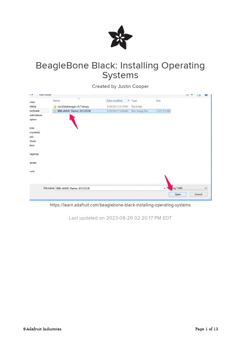
BeagleBone Black: Installing OperatingSystemsCreated by Justin Cooperhttps:///beaglebone-black-installing-operating-systemsLast updated on 2023-08-29 02:20:17 PM EDT33445571012Table of ContentsOverviewChoosing an Operating SystemAngstrom• Download• Default User/Password and SSH Ubuntu• Download• Default User/Password and SSH Copying the Image to a microSD CardWindowsMac OS X• Using a GUI• Using the command line Flashing the BeagleBone BlackFAQOverviewThe BeagleBone Black includes a 2GB or 4GB on-board eMMC flash memory chip. It comes with the Debian distribution factory pre-installed. You can flash new operating systems including Angstrom, Ubuntu, Android, and others. The following pages will illustrate the steps to getting the latest of each type of supported distribution onto the on-board eMMC.In addition to the eMMC, you can also boot directly from a microSD card similarly to the original BeagleBone.Choosing an Operating SystemThere are a few operating systems you can choose to use on your BeagleBone Black. The following sub-pages include the download location, and some useful information about each operating system you may want to use.Angstrom, Ubuntu, and Debian all appear to have stable images.Android is currently working from a 3rd party build. We don't have a guide on how toinstall this as of yet.AngstromAngstrom is the default Linux distribution that is pre-installed on the eMMC on the BeagleBone Black. It's a stripped down version of Linux specifically designed for embedded devices.Depending on how long ago you purchased your BeagleBone Black, you may not have the latest version of Angstrom installed. It's usually preferable to get the latest version, especially this early in the product's lifecycle.DownloadTo start with, download the latest version of Angstrom for the BeagleBone Black. You can find the latest version at the BeagleBoard Latest Images () page. Once you've downloaded the file, you'll want to jump to the section for your specific OS (Mac OS X, Linux, Windows).Default User/Password and SSHThe default login user/password for angstrom is "root". There is no password set, so you can bypass the password prompt by just hitting enter without typing anything in. Angstrom comes with the Avahi Daemon pre-installed. This is really useful because you can now ssh in simply by using 'beaglebone.local' instead of trying to find the IP address. For example, type this into your favorite terminal:************************UbuntuUbuntu is an unsupported operating system for the BeagleBone Black (BBB), but does have quite a few users, and a stable image with the 3.8 Linux kernel. DownloadTo start with, download the latest version of Ubuntu for the BeagleBone Black. You can find the latest version at the Ubuntu software support page (). Choose the file that is compatible with flashing to the eMMC. Once you've downloaded the file, you'll want to jump to the section for your specific OS (Mac OS X, Linux, Windows).It is important that you download a version of Ubuntu specifically built for the BeagleBone Black unless you're an expert at configuring Linux and working with thekernel. It's not necessary to download the most recent version, but it's highly recommended. The BBB ecosystem is rapidly changing, and each release offers many new improvements.Default User/Password and SSHIf you've used the the image to flash Ubuntu to the eMMC, the default username for Ubuntu 13.04 (Raring Ringtail) is "ubuntu". The default password is 'temppwd'. Ubuntu does not come with the avahi daemon pre-installed, so you'll need to ssh in using the IP address using your favorite terminal:**************.1.15Copying the Image to a microSD CardOnce you've downloaded an image for the operating system you're interested in using, you'll need to copy it to a microSD card in order to flash it onto the BeagleBone Black's built-in eMMC flash. It sounds confusing, but it's rather simple.Navigate to the next sub-page for the host operating system you'll be using to copy the image to the microSD card.WindowsOnce you've downloaded the img.xz file, in my case it is titled BBB-eMMC-flasher-2013.05.08.img.xz, you'll need to extract the archive. To extract the archive, you'll want to download and install 7zi ()p. 7zip is a free and open source utility that is able to extract img.xz files (among many other file types!).It will take a minute or two to extract the file, and you should then end up with a 3.66 GB .img file (notice that the .xz is removed from the file extension).Next, download the free Win32 Disk Imager () software that we'll use to copy theimage to the microSD card. After downloading the software, extract it from the zip file (7zip can be used here as well).Launch the Win32 Disk Imager Software by double clicking the "Win32DiskImager"file in the folder that you extracted it to. You should see the following screen once it launches:Click the folder icon (arrow pointed to it above), and choose the image file, and click Open:Next, insert your SD card, and choose the correct "Device" drive letter. You may want to open windows explorer to help figure out which one to choose. Another way is to view the drive letters by clicking the dropdown below "Device", and then inserting your SD card to see which one gets added to the list.Once you've made your selections, click the "Write" button illustrated above, and wait for it to complete writing to your SD Card.You can now continue on to the Flashing the BeagleBone Black () page to continue. Mac OS XOnce you've downloaded the img.xz file, in my case it is titled BBB-eMMC-flasher-2013.05.08.img.xz, you'll need to extract the archive. I've found the easiest utility to use is called "The Unarchiver". You can find it on the app store, or from their site (). Once you've installed "The Unarchiver", just navigate to the .img.xz file, typically located in Finder in the "Downloads" section, and double click the file to begin extraction.It will take a minute or two to extract the file, and you should then end up with a 3.66 GB .img file (notice that the .xz is removed from the file extension).There are now a few ways to continue. You can use terminal commands, or software that will guide you through it. Let's start with the guided software using a graphical interface.Using a GUIFirst, you'll want to download PiFiller (). It was designed to install images onto SD cards for the Raspberry PI, but there isn't any reason why it wouldn't work for BeagleBone images as well.Once you've downloaded Pi Filler, locate it in Finder (typically Downloads), and double click it to extract it. You may want to copy it to your Applications folder.Launch Pi Filler, and follow the on-screen prompts. The first thing it will ask is for you to locate your .img file. It mentions the Raspberry Pi, but you can ignore that, it doesn't make any difference.Select the appropriate .img file, and click "Choose".Then, insert your microSD card into your Mac, and click Continue. Pi Filler will look foryour SD Card, and then notify you once it finds it.Click Continue once you're certain its found the correct SD card.It can take 15-20 minutes to write the image to the microSD card. Once it's complete, remove the microSD card and insert it into the powered down BeagleBone Black. You will only be able to insert the card one way, and it needs to snap in fully. Navigate to the Flashing the BeagleBone Black () page, and follow the instructions on how to flash the newly copied image onto the on-board flash memory of the BeagleBone Black.Using the command lineAnother alternative is to flash the microSD card entirely from the command line. You'll first want to extract the img.xz file you've downloaded, and the best program for that is still "The Unarchiver" mentioned in the GUI instructions. Once you've got the extracted .img file, open a terminal to get started.Execute the following command to see the list of connected storage devices:df -hNext, insert your microSD card, and then execute the following command again:df -hCompare the two outputs, and find the newly added device. In my case, the microSD card was '/dev/disk4s1'.Once you've got the name of the device, you'll want to unmount that disk using the following command, but replacing the specifics with your card details:sudo diskutil unmount /dev/disk4s1Now, you'll want to execute the command that actually copies the image onto the SD card. You have to be really careful here, and make sure you're entering the correct device details. You could end up copying over the wrong drive, such as your master hard disk, and then you'd end up having a bad day. Double check everything!Note that we subtly changed the device name from "/dev/disk4s1" to "/dev/rdisk4". You'll want to do the same when you execute the below command.Also, choose the right file location for your .img file in the input file field (if=...).sudo dd bs=1m if=~/Downloads/BBB-eMMC-flasher-2013.05.08.img of=/dev/rdisk4This process can take anywhere from 15-30 minutes depending on the speed of your computer and microSD card. Once it has completed, remove the microSD card, and insert it fully into the BeagleBone Black microSD card slot.Navigate to the Flashing the BeagleBone Black () page, and follow the instructions on how to flash the newly copied image onto the on-board flash memory of the BeagleBone Black.Flashing the BeagleBone BlackNow that you have the latest image of Angstrom loaded onto your microSD card slot, you'll need to flash it onto the on-board flash memory of the BeagleBone Black.To start, make sure the BeagleBone Black is powered down, and unplugged from thepower source.Now, insert the microSD card into the slot on the back of the BeagleBone Black. It should snap into place.Now, find the "User Boot" button. it's located on the same side of the BeagleBone Black as the microSD card slot, and is the only button in that area. See the below screenshot (from ) highlighting the 'User Boot" button.Hold the "User Boot" button down, and then plug in the power (USB or 5V adaptor). Keep holding down the button until you see the bank of 4 LED's light up for a few seconds. You can now release the button.It will take anywhere from 30-45 minutes to flash the image onto the on-board chip. Once it's done, the bank of 4 LED's to the right of the Ethernet will all turn off. You can then power down your BeagleBone Black.Remove the SD Card, and power up your BeagleBone Black.FAQWhen I attempt to flash the OS onto the on-board eMMC memory, nothing happens. What do I do?If you've followed the "Flashing the BeagleBone Black" instructions exactly, and nothing really happens when you attempt to flash it (the 4 LED's don't light up),then you can try the following suggestions:Ensure you have a good power supply. This is the most important thing as flashing the BBB is pretty power intensive. The USB power supply featured in this guide is fully capable.Unplug the Ethernet while flashing. It can consume a bit of powerunnecessarily.Try again. Sometimes it can take a couple of tries to get the process going.Also, make sure you've held the user boot button down the entire time until the LED's light up, prior to plugging in the power. Re-seat the SD card.Copy the image to your SD card again. It's possible that this process wasn't fully successful.How do I use ssh-keygen to generate ssh keys on Angstrom?Angstrom comes pre-installed with the dropbear ssh package by default, instead of the more common openssh package. The easiest way to generate ssh keys is to simply install the openssh-keygen client.You can do this by executing the following command:opkg update ; opkg install openssh-keygen1. 2. 3. 4.How do I set the time and date? It's always wrong when I reboot.There are a few options. The first would be to setup a real time clock breakout board.Another option is to execute the following command (configure it to execute on startup as well):/usr/bin/ntpdate -b -s -u How can I use opkg upgrade on Angstrom?Execute the following commands. tmpfs is quite small on the default Angstrom installation.opkg --tmp-dir ~ updateopkg --tmp-dir ~ upgrade。

Board Porting\Bring up using Processor SDK RTOS for AM335xProcessor SDK RTOS component known as board library consolidates all the board-specific information so that all the modifications made when moving to a new custom platform using the SOC can be made in the source of this library.There are three different components in PRSDK that help in porting and bring up of a custom board:∙Board library updatesa.PLL Clocking and PRCMb.Pin mux Updatec.DDR Configurationd.Peripheral instances updates∙Diagnostics tests∙Boot loader updatesBoard Library Updates in Processor SDK RTOS:PLL ClockingThere are two places where the device PLL configurations are performed when using Processor SDK RTOS and CCS.Debug environment:Debug environment refers to development setup where code is debugged using JTAG emulator on the SOC. The PRSDK software relies on the GEL file that is part of the target configuration to setup the clocks and the DDR for the device. The CCS GEL file for AM335x platforms is located in the CCS package at the location ccsv7\ccs_base\emulation\boards\<boardName>For example for beagle bone black, the files can be found atccsv7\ccs_base\emulation\boards\beaglebone\gelThe GEL is the first piece of software that should be brought up on a custom board.Production environment:Production environment refers to the setup when the base application is booted from a boot media like a flash memory or host interface. In this environment, the bootloader sets performs all the SOC and board initialization and copies the application from flash memory to the device memory.The clock setup in the bootloader code can be located atpdk_am335x_x_x_x\packages\ti\starterware\bootloader\src\am335xUsers can choose to use the platform clocking similar to one of TI reference platforms or can modify them as per their application requirements. By default the PLL settings are setup for OPP_NOM settings (MPU= 600 MHz.)TI provides Clock Tree tool to allow users to simulate the clocking on the SOC. For quick reference of the multiplier and divider settings to change the PLL setting is provided in the spreadsheetAM335x_DPLL_CALCv3.xlsx.After modifying the clocking in the bootloader, users need to rebuild the bootloader using instructions provided in Processor_SDK_RTOS_BOOT_AM335x/AM437xPRCM Modules Enable:PRCM Module Enable is required to turn on the power domain and the clocking to each of the modules on the SOC. The PRCM Enable calls to enable each module are made from the functionBoard_moduleClockInit which is found in the location.pdk_am335x_1_0_9\packages\ti\board\src\bbbAM335x\bbbAM335x.cCheck every instance and peripheral required in the application platform and enable the module in the board library.For example to use three UARTs 0, 1 and 4, ensure that you have the following code as part of the board library setup:/* UART */status = PRCMModuleEnable(CHIPDB_MOD_ID_UART, 0U, 0U);status = PRCMModuleEnable(CHIPDB_MOD_ID_UART, 1U, 0U);status = PRCMModuleEnable(CHIPDB_MOD_ID_UART, 4U, 0U);Note: PRCMEnable function is defined in pdk_am335x_1_0_9\packages\ti\starterware\soc\am335x Pinmux updates in the Board library:Generating a New PinMux Configuration Using the PinMux Utility: This procedure uses the cloud-based pinmux utilityNavigate to ${PDK_INSTALL_DIR}\packages\ti\starterware\tools\pinmux_config\am335x and Load beaglebone_black_configAdd and remove peripheral instances and select the appropriate use cases required for development based on the application platform requirements and resolve all conflicts.Refer Pin_Mux_Utility_for_ARM_MPU_ProcessorsPost Processing steps:1.Change the Category filter to starterware and download the pinmux files am335x_pimnmux.hand am335x_pinmux_data.c2.At the bottom of am335x_pinmux.h change extern pinmuxBoardCfg_t gAM335xPinmuxData[];to extern pinmuxBoardCfg_t gBbbPinmuxData[];3.Change am335x_pinmux_data.c to am335x_beagleboneblack_pinmux_data.c.4.Change gAM335xPinmuxData to gBbbPinmuxData at the end of the file in file5.am335x_beagleboneblack_pinmux_data.c.Replace the existing files with the new files and rebuild the board library using the instructions in the section Rebuilding board Library in Processor SDK RTOS:Updating DDR settings:Similar to clock and PLL settings, DDR initialization is configured in the Debug environment through GEL files and in production environment using bootloader source files.TI provides AM335x_EMIF_Configuration_tips which contains a spreadsheet to enter the timing from the DDR datasheet to compute the EMIF timing number required to initialize DDR.We strongly recommend changing the value and testing using GEL files before using them in the bootloader software. For Sanity test, you can perform read/write tests using CCS Memory Browser or run the diagnostic memory read/write test that we provide in diagnostics package here:PDK_INSTALL_PATH\packages\ti\board\diag\memOnce the DDR timings have been confirmed, you can use the settings in the file:PDK_INSTALL_PATH \packages\ti\starterware\bootloader\src\am335x\sbl_am335x_platform_ddr.c Peripheral initialization:The board library is responsible for most of the SOC initialization but it also setup some board level components such as ethernet PHY and debug UART and I2C for reading board ID from EEPROM. All of the other peripheral instances and initialization needs to be done from the application level.For example for beagleboneblack, the peripheral initialization are performed from the source filepdk_am335x_1_0_9\packages\ti\board\src\bbbAM335x\bbbAM335x_lld_init.cThe debug UART instance, I2C Addresses are set using the file board_cfg.h found under:pdk_am335x_1_0_9\packages\ti\board\src\bbbAM335x\includeDefault UART instance is set to 0 in the board library. The Board initialization will configure the UART instance 0 to send binary log data to serial console using the Board_UARTInit function. If you wish to use more UART instances then we recommend linking in the UART driver in the application and using UART_open() and UART_stdioInit API calls from the application.Each peripheral driver in the Processor SDK RTOS has a SOC configuration that provides the interrupt numbers, base address, EDMA channels which can be updated using the file <peripheral>_soc.c file. This is used as default setup for initializing the driver instance. It can be overridden from the application using peripheral_getSOCInitCfg() and peripheral_setSOCInitCfg()For Example: All instances of UART for AM335x have been mapped in the filepdk_am335x_1_0_9\packages\ti\drv\uart\soc\am335x\UART_soc.cSystem integrators need to ensure that no interrupt numbers and EDMA resource conflicts exist in the SOC configuration for all drivers used in the system.To exercise three UARTs in the system, users can use the following code://Setup Debug UARTboardCfg = BOARD_INIT_PINMUX_CONFIG |BOARD_INIT_MODULE_CLOCK |BOARD_INIT_UART_STDIO;Board_init(boardCfg);// Open Additional UART Instances:/* UART SoC init configuration */UART_initConfig(false);/* Initialize the default configuration params. */UART_Params_init(&uartParams);// Open UART Instance 1uartTestInstance =1;uart1 = UART_open(uartTestInstance, &uartParams);//Open UART Instance 4uartTestInstance = 4;uart4 = UART_open(uartTestInstance, &uartParams);BoardID Detect:TI supports multiple evaluation and reference platforms for AM335x hence the hardware platforms are populated with an EEPROM which contains information that identifies the hardware and its revision. The board library and software components read the boardID and initialize the platform based on the boardID. The BoardID_detect function can be found in the source in the file bbbAM335x_info.c in the board library and board_am335x.c in the bootloader source at:<PDK_INSTALL_PATH>\packages\ti\starterware\board\am335xRebuilding board Library in Processor SDK RTOS:While Creating a new folder for the custom board is an option users can explore, TI recommends that users make there changes in existing board package using either bbbAM335x, evmAM335x oriceAM335x folder to avoid spending additional effort to modify the build files for including the customBord.Once all the update to the board library are completed, the board library can be updated using the following instructions.Instructions to rebuild board library:Setup Processor SDK build environment before following steps provided below.cd pdk_am335x_1_0_9\packagesgmake board_libFor a specific board users are required to provide the LIMIT_BOARDS argument.LIMIT_BOARDS : evmAM335x icev2AM335x iceAMIC110 bbbAM335x skAM335xFor Example for beagleboneblack, users can use the following build option:gmake board_lib LIMIT_BOARDS=bbbAM335xDiagnostics:After the board library is built, we highly recommend that you create a diagnostics package similar to one provided in board library to test different interfaces functionally during board bring up.The diagnostics package can be located at pdk_am335x_1_0_9\packages\ti\board\diag. These are simple bare-metal tests that use peripheral drivers to help functionally validate the pins and interfaces.Documentation for all available diagnostic tests is provided here:/index.php/Processor_SDK_RTOS_DIAGBootloader in Processor SDK RTOS:As part of the production flow, users are required to develop/port flashing and booting utilities so the application can be launched on the custom board with JTAG. TI provides a bootloader mechanism where the ROM bootloader loads a secondary bootloader on the onchip memory that initializes the SOC and DDR and then copies the application into DDR memory.The boot process and flashing tools have been described in detail in the following article that is part of processor SDK RTOS Software developer`s guide:/index.php/Processor_SDK_RTOS_BOOT_AM335x/AM437x#Building_the_B ootloader。

玩转BeagleBoard xM——建立虚拟机开发环境和嵌入式Linux系统分类:beagleboard xM linux kernel rootfs 2012-07-28 10:36 343人阅读评论(0) 收藏举报在Beagleboard xM(简称bb)上建立能运行Linux系统,包括了创建启动用的TF卡,编译生成bootloader(MLO和u-boot.bin),编译生成内核镜像文件(uImage或zImage 文件),创建rootfs(Linux根文件系统)等工作。
这些工作需要在一台配置ARM交叉编译环境的Linux系统上完成。
下面分步完成整个系统的建立过程,直至Linux系统在bb上boot起来,进入shell命令行。
STEP 1:建立ARM嵌入式开发环境利用ARM交叉编译环境,可以x86系统上,编译ARM处理器上可执行的目标代码。
主要用于编译bb上的bootloader、内核镜像,以及其它ARM可执行程序。
具体步骤:(1)在VMware上创建一个虚拟机,安装发行版的ubuntu系统,用于建立ARM嵌入式开发环境。
(2)安装arm-linux-gcc,建立ARM交叉编译环境(需要root权限)1、下载arm-linux-gcc-4.3.2.tgz压缩包2、tar -xzvf arm-linux-gcc-4.3.2.tgz,自动解压至/user/local/arm/目录下。
ARM交叉编译器的所有可执行程序在/usr/local/arm/4.3.2/bin/目录下。
3、配置root用户环境变量,修改/etc/bash.bashrc文件#vi /etc/bash.bashrc在最后加上export PATH=$PATH:/usr/local/arm/4.3.2/bin4、测试arm-linux-gcc -v,会执行编译器,正常显示版本信息表示已安装配置成功STEP 2:创建bootloader和boot.scrTI OMAP系列处理器上的bootloader专指x-loader(MLO)和u-boot(u-boot.bin),两者用于完成Linux内核启动前的配置部分硬件系统配置,解压加载内核Image文件并引导内核启动。

Setting up WiFi with BeagleBone BlackCreated by Tony DiColahttps:///setting-up-wifi-with-beaglebone-blackLast updated on 2023-08-29 02:36:55 PM EDT347Table of ContentsOverviewHardware• HDMI Port Interference• PowerConfiguration• Kernel Upgrade• WiFi Reset Service• WiFi ConfigurationOverviewHave you been pulling your hair out trying to get WiFi working consistantly on a BeagleBone Black? Don't worry there are some easily solved problems that could be causing your WiFi grief! For example did you know the HDMI port can interfere with small WiFI adapter antennas? Or that you can upgrade the Linux kernel to improve WiFi driver stability? Follow this guide to learn how to avoid common pitfalls and configure your BeagleBone Black to work with a USB WiFi adapter!Before you get started make sure you're running the latest official Debian image () on your BeagleBone Black. It's very important to use the Debian operating system on your BeagleBone Black to follow this guide! If you aren't familiar with how to install an operating system on the device, check out this handy BeagleBone Black operating system install guide ().Also if you are new to the BeagleBone Black you will want to familiarize yourself with how to connect to it and interact with the command shell using SSH. This guide will show you the basics of accessing the BeagleBone Black with SSH ().HardwareTo setup WiFi with your BeagleBone Black you'll need a USB WiFi adapter that is compatible with the BeagleBone Black's Debian operating system. Be sure to read the BeagleBone Black wiki's list of known working WiFi adapters () and consider using a device from that list.Unfortunately the choice of WiFi adapter for the BeagleBone Black is a littlemore complicated compared to other Linux boards like the Raspberry Pi. The BeagleBone Black's official Debian image uses an old version 3.8 of the Linux kernel compared to more recent versions like 3.15+. Since WiFi drivers are typically included in the Linux kernel source, running an old kernel means running old and potentially buggy WiFi adapter drivers.Out of the box the 3.8 kernel seems to have problems with popular WiFi adapters, like the Realtek-based adapters in the Adafruit store. In particular you might experience problems like the WiFi adapter randomly not connecting to a wireless network on boot. I'll show later in the guide that a simple script to reset the wireless adapter on boot greatly improves reliability of Realtek and other adapters on the BeagleBone Black.If you're a more experienced Linux user you might be wondering if you can upgrade the Linux kernel to a later version like 3.14 or 3.15 to get more reliable WiFi drivers.You can, but you need to be careful because later kernels right now don't support the same functionality, like device tree overlays (), as the 3.8 kernel. Kernel support beyond 3.8 is improving every day so you should search and consult the BeagleBoneBlack support group () for the latest information on kernel stability and feature support if you want to use a newer kernel. I'll show later in the guide how to make sure you're using the latest 3.8 version kernel so you're getting the most up to date drivers.HDMI Port InterferenceOne common issue with WiFi on the BeagleBone Black is poor performance from WiFi adapters with small internal antennas. The problem is that the ground and power planes of the HDMI port are right below the USB port and dampen the WiFi signal (). This will manifest as poor signal quality and reliability with small USB WiFi adapters that are very close to the USB port.There are two ways to deal with this interference issue, one is to use a small USB extension cable / adapter (http://adafru.it/974) or small USB hub (http://adafru.it/961) (e ven an unpowered hub would work fine) to move the WiFi adapter farther away from the BeagleBone Black. For example the photo below shows a small hub that moves a tiny WiFi adapter away from the BeagleBone Black:A second option is to completely disable the HDMI port by manipulating the device tree (). This option is only possible if you do not need to output any video or audio signal over the HDMI port!Of the two options I would stick with the first, moving the adapter away from theboard, since it's simpler and will still let you use the HDMI port. However if you can'tmove the WiFi adapter away you can follow the steps below to disable HDMI.First connect your BeagleBone Black's USB port to your computer and connect to it with SSH (). Then mount and edit the uEnv.txt file that controls boot configuration by executing:mkdir /mnt/bootmount /dev/mmcblk0p1 /mnt/bootnano /mnt/boot/uEnv.txtYou should see the nano text editor appear with the contents of the uEnv.txt file like this:Notice the lines in the middle that mention disabling HDMI:##Disable HDMI#cape_disable=capemgr.disable_partno=BB-BONELT-HDMI,BB-BONELT-HDMINRemove the # in front of the cape_disable command so it looks like:##Disable HDMIcape_disable=capemgr.disable_partno=BB-BONELT-HDMI,BB-BONELT-HDMINBe careful to edit the correct line! If you disable the HDMI/eMMC line you might disable booting from the internal flash memory of the BeagleBone Black.Save the file by pressing Ctrl-O and then Enter. Finally quit nano by pressing Ctrl-X.Reboot your BeagleBone Black and it should have the HDMI port disabled.If you need to enable the HDMI port again just edit the uEnv.txt file with the same procedure above and add the # comment back in front of the disable HDMI line. PowerFinally make sure you are powering your BeagleBone Black with a sufficient power supply to support your WiFi adapter. Most computer or laptop USB ports do not supply enough power to support a BeagleBone Black and WiFi adapter!Make sure you're using a 5 volt power supply with at least 1 amp or more of current. You can plug a simple external 5V power supply (http://adafru.it/276) right into the BeagleBone Black's barrel jack.Don't skimp on powering your device properly or else you will have instabilityand poor WiFi performance!ConfigurationOnce you have the hardware setup you're ready to configure the BeagleBone Black to use your WiFi adapter.Kernel UpgradeFirst you will want to make sure you're running the very latest version of the 3.8 series kernel. Like mentioned in the previous page, you want to use the most recent Linux kernel to get the most recent and stable WiFi drivers. Luckily you don't need to be a Linux expert to upgrade the kernel because a script is included with your BeagleBone Black's Debian installation to automatically upgrade to the latest stable 3.8 version kernel.In my testing I found upgrading the BeagleBone Black's kernel was mandatory to get reliable WiFi performance. Don't skip this step, be sure to upgrade the kernel! Make sure your device is connected to the internet (through the ethernet port for example), power it on, and connect to the terminal with SSH. Run the following commands to start the kernel upgrade:cd /opt/scripts/tools/./update_kernel.shYou should see the script download a kernel image and perform the installation automatically. After a few minutes the uprade will complete and tell you to reboot your device. Follow the instructions and reboot by executing the command:rebootAfter the device reboots the kernel upgrade is complete!WiFi Reset ServiceThe next step is to install a small script that will reset the WiFi interface by bringing it down and back up again automatically on boot. With the latest 3.8 kernel I found this reset script was necessary to get reliable performance with Realtek and some Atheros WiFi adapters, so don't skip installing it! Later kernels or more stable adapters might not require the reset service, but it can't hurt to install it for them too.To install the service connect again to the device in a terminal with SSH and execute these commands:cd ~ntpdate -b -s -u apt-get update && apt-get install gitgit clone https:///adafruit/wifi-reset.gitcd wifi-resetchmod +x install.sh./install.shAfter executing the install.sh script you should see a response like the following: Installing wifi reset service to /opt/wifi-reset.Installing systemd service to run at boot.Enabling systemd service.If you see an error message, go back and carefully check the commands above were executed.That's all you need to do to install the wifi reset service!Note that if you'd ever like to disable the WiFi reset service you can execute this command to do so:systemctl disable wifi-reset.serviceWiFi ConfigurationFinally it's time to configure the wireless connection for your BeagleBone Black. To start, power down the device completely and insert the WiFi adapter into the USB port. Remember the HDMI port can cause interference so you might need to use a small extension or hub to move your adapter away from the board!Power up your BeagleBone Black and connect to it in a terminal with SSH, then run the following command to list any wireless interfaces available:iwconfigYou should see a response with a wlan0 name and some details about the wireless adapter's capabilities. For example I see the following response for my adapter:wlan0 IEEE 802.11bgn ESSID:off/anyMode:Managed Access Point: Not-Associated Tx-Power=0 dBmRetry long limit:7 RTS thr=2347 B Fragment thr:offEncryption key:offPower Management:onlo no wireless extensions.eth0 no wireless extensions.usb0 no wireless extensions.Note that if you see a different name than wlan0, like ra0, take note of that name as it will be used in the configuration later.Now you'll edit the /etc/network/interfaces file to specify WiFi network connection details. Run the following command to open the nano text editor:nano /etc/network/interfacesYou should see a file like the following appear:Notice there's a commented block showing a WiFi configuration example:# WiFi Example#auto wlan0#iface wlan0 inet dhcp# wpa-ssid "essid"# wpa-psk "password"Configuring most WiFi networks is as easy as uncommenting the lines and filling in the details for your network. For example if I were connecting to a WiFi network with name "adafruit" and password "mypassword" I would edit the configuration to look like:# WiFi Exampleauto wlan0iface wlan0 inet dhcpwpa-ssid "adafruit"wpa-psk "mypassword"If you're connecting to a more complex WiFi network, such as one with a 'hidden' SSID or that needs a static IP address, you might need to add more to the configuration. Check out the guide on setting up WiFi with a Raspberry Pi () as the configuration in /etc/network/interfaces is the same on the BeagleBone Black as the Raspberry Pi.Also be aware that if you found the iwconfig command returned a different interfacename, like ra0, you should change all references from wlan0 to the appropriateinterface name.Once you've modified the file, save it by pressing Ctrl-O and Enter, then press Ctrl-X to quit nano.Now test the connection by running the following to bring up the WiFi connection manually:ifup wlan0Again change wlan0 to the name of your WiFi interface if you found it differed with the iwconfig command.If the WiFi connection is made with your network you should see an IP address acquired with DHCP:Internet Systems Consortium DHCP Client 4.2.2Copyright 2004-2011 Internet Systems Consortium.All rights reserved.For info, please visit https:///software/dhcp/Listening on LPF/wlan0/e8:de:27:11:62:7cSending on LPF/wlan0/e8:de:27:11:62:7cSending on Socket/fallbackDHCPDISCOVER on wlan0 to 255.255.255.255 port 67 interval 6DHCPDISCOVER on wlan0 to 255.255.255.255 port 67 interval 9DHCPREQUEST on wlan0 to 255.255.255.255 port 67DHCPOFFER from 192.168.1.1DHCPACK from 192.168.1.1bound to 192.168.1.127 -- renewal in 36491 seconds.The exact response might differ, but the important thing is that you receive a DHCPOFFER response and are assigned an IP address.You can also confirm the BeagleBone Black is connected to the network by running the following command to list network details:ifconfig wlan0If your device is connected to the network it should show connection details with an IP address (192.168.1.127 in my case) like:wlan0 Link encap:Ethernet HWaddr e8:de:27:11:62:7cinet addr:192.168.1.127 Bcast:192.168.1.255 Mask:255.255.255.0inet6 addr: fe80::eade:27ff:fe11:627c/64 Scope:LinkUP BROADCAST RUNNING MULTICAST MTU:1500 Metric:1RX packets:15413 errors:0 dropped:0 overruns:0 frame:0TX packets:3301 errors:0 dropped:0 overruns:0 carrier:0collisions:0 txqueuelen:1000RX bytes:21575587 (20.5 MiB) TX bytes:323282 (315.7 KiB)Finally you can test internet access by trying to ping a website such as by executing:ping You should see successful ping responses such as:PING (207.58.139.247) 56(84) bytes of data.64 bytes from (207.58.139.247): icmp_req=1 ttl=52 time=86.1 ms64 bytes from (207.58.139.247): icmp_req=2 ttl=52 time=85.8 ms64 bytes from (207.58.139.247): icmp_req=3 ttl=52 time=87.0 ms64 bytes from (207.58.139.247): icmp_req=4 ttl=52 time=87.8 ms64 bytes from (207.58.139.247): icmp_req=5 ttl=52 time=86.1 ms64 bytes from (207.58.139.247): icmp_req=6 ttl=52 time=86.7 ms64 bytes from (207.58.139.247): icmp_req=7 ttl=52 time=86.5 ms Press Ctrl-C to quit the ping application.If any of the checks above fail or indicate no network access, carefully check the details in the /etc/network/interfaces file are correct for your wireless network and try again.Now the final test is to reboot your BeagleBone Black to verify the wireless connection is made automatically. Execute the following to reboot the device:rebootOnce the device has rebooted, connect to it in an SSH session and run the network connection tests above again. If they show you're connected to the network, congratulations you've successfully configured your BeagleBone Black to work with WiFi!If the device fails to connect on boot, try running the following to manually reset the WiFi connection:ifdown wlan0ifup wlan0Again changing wlan0 to match the name of the interface you found earlier.If the ifup command fails to get an IP address, go back and check the WiFi network details in /etc/network/interfaces are correct for your network and try again. If you still can't get a connection to work, try posting details about the WiFi adapter you're using and the error or issue you're hitting on the BeagleBone Black support group () o r the Adafruit forums ().。

1Starterware: BeagleBone Black supportIntroductionThis document describes the procedure to add a support in StarterWare package for BeagleBone Black by changingthe existing BeagleBone White bootloader. It also explains the changes made in the code on abstract level. After applying the changes, the new bootloader code will work on both the platforms (BeagleBone White and BeagleBone Black). You need to apply the above changes in StarterWare 02.00.01.01 [1] release.Changes made in the original BeagleBone White bootloader1. Setting the maximum OPP configuration for the SOC based on the device revision and the EFUSE value if applicable. (Note: EFUSE value does not apply for the device revision PG1.0 and it is always 0. Refer section 1.2.12in TRM [2]).•For PG1.0, operating performance point TURBO is selected with MPU frequency 720 MHz.•For PG2.x, operating performance point is selected based on the EFUSE value if correctly blownNote :•Experimental devices whose package name starts with ‘X’, EFUSE value may show 0 or invalid value.For value 0, operating performance point is set to TURBO with MPU frequency 800 MHz and forinvalid value, operating performance point is set to OPP50 with MPU frequency 300 MHz.•For different operating performance point and MPU frequency settings refer section 3.2 in AM335X datasheet [3].2. To allow the bootloader to work for both BeagleBone White and BeagleBone Black, board identification logic is added.•EEPROM on the Board stores the information related to board. BeagleBone White has the board name “A335BON” and BeagleBone Black has the board name "A335BNL".•If the board is found to be BeagleBone White, it is configured for DDR2 memory.•If the board Is found to be BeagleBone Black, it is configured for DDR3 memory.3.BeagleBone Black configuration for DDR3 memory.•PMIC is configured to generate 1.5V required by DDR3.•DDR PLL is configured to generate 400 MHz required by DDR3.•Timing parameters required by DDR3 are set.•You can refer the BeagleBone Black gel file for the timing parametres generated in "\tools\gel" as AM335X_beagleboneblack.gel.•You can also refer this link [4] which shows the procedure to tune the timing for DDR3.How to apply changes?You can follow the following steps either on Windows or on Linux to add a support for BeagleBone Black in the existing StarterWare installation. (Note: Make sure you are applying changes to StarterWare 02.00.01.01 release) Step 1 : Download the tar.gz file and keep it in the existing StarterWare installation directory.Step 2 : unzip and untar the downloaded file and Select 'Yes' when asked to merge any folder or copyand replace a file.It will automatically replace the following four files in their respective directories.•beaglebone.h2•bl_platform.c•bl_platform.h•hw_tps65217.h•MLO(Note: This is a prebuilt MLO for BeagleBone Black and it will work for both theplatforms now)It will also add the following files as a BeagleBone Black support•BBB_manual.pdf in "\docs\"•AM335X_beagleboneblack.gel in "\tools\gel\"Step 3 : Build your bootloader code.After building, new bootloader binary is ready to work for both the platforms.How to run a demo application?•Locate the new bootloader binary in the following directory based on the tool chain being used.GCC: "\binary\armv7a\gcc\am335x\beaglebone\bootloader\Release_MMCSD\"CCS: "\binary\armv7a\cgt_ccs\am335x\beaglebone\bootloader\Release_MMCSD\"•Rename the bootloader binary image appended with the TI Image Header boot_ti.bin with MLO.•Further steps to run a demo application on BeagleBone Black are same as BeagleBone White. You can refer this link [5] to run a demo application.Note :•To run a simple LED blink example you can follow the same steps as explained above by renaming the gpioLedBlink_ti.bin file with app, found in the following directory based on the tool chain being used.GCC: "\binary\armv7a\gcc\am335x\beaglebone\gpio\Release_MMCSD\"CCS: "\binary\armv7a\cgt_ccs\am335x\beaglebone\gpio\Release_MMCSD\"You can also find a prebuilt MLO file compatible for both the platforms generated in the booloader binary folder after applying this patch.References[1]/dsps/dsps_public_sw/am_bu/starterware/latest/index_FDS.html[2]/wiki/images/7/72/AM335x_techincal_reference_manual.pdf[3]/lit/gpn/am3359[4]/index.php/Sitara_Linux_Training:_Tuning_the_DDR3_Timings_on_BeagleBoneBlack[5]/index.php/Quick_Start_Guide_StarterWare_02.00.XX.XX_(supports_AM335x)3 Article Sources and ContributorsStarterware: BeagleBone Black support Source: /index.php?oldid=179852 Contributors: Baskaran, X0211877。

BeagleBone Black eMMC烧写全记录(基于AM335x SDK06)eMMC存储介质目前越来越广泛的应用在嵌入式系统中,AM335x的用户也越来越多的使用EMMC作为系统的主要存储介质。
目前AM335x的几款官方demo板中,只有BeagleBone Black上加入了对eMMC芯片的支持,很多用户也是参考BeagleBone Black进行自己AM335x系统的eMMC设计。
笔者最近分别通过TI Uniflash和SD卡完成了BeagleBone Black上eMMC芯片的烧写验证工作,软件基于AM335x Linux SDK06,总结出来供大家参考。
1.使用TI UniFlash工具通过USB RNDIS烧写1.1 TI Uniflash 简介Uniflash是TI开发的存储器烧写工具,可以支持AM335x系统的NAND Flash,NOR Flash, SPI Flash,eMMC烧写。
可以参考wiki上的guide:/index.php/Sitara_Uniflash_Quick_Start_Guide,在Windows宿主机上下载并安装Uniflash,并按照其中3.3节所述在Windows宿主机上安装USB RNDIS 驱动。
1.2 eMMC 烧写原理本文介绍的验证方法是使用Uniflash工具通过USB 对BeagleBone Black上的eMMC进行烧写,原理是通过Romcode,SPL和u-boot三个阶段,将一个专门用于eMMC烧写的Linux操作系统在BeagleBone Black板上运行起来,并自动运行脚本进行烧写。
第一阶段,通过设置AM335x的sysboot管脚,使AM335x的启动项包含USB0启动。
BeagleBone Black的默认启动设置为:MMC1->MMC0->UART0->USB0,MMC1和MMC0分别连接了eMMC和SD卡,如果eMMC为空,并且不插SD卡,芯片上电后执行的Romcode就会执行USB启动。


Enabling AMP on ContentSecurity Products (ESA/WSA)January 2017Version 2.2Bill Yazji****************C O N T E N T S E C U R I T Y–A M P B E S T P R A C T I C E SOverview:The vast majority of threats, attacks and nuisances faced by an organization often come through email in the form of spam, malware and blended attacks, as well as via normal every day web browsing.Cisco’s Email Security Appliances and Web Security Appliances include several different technologies and features to cut these threats off at the gateway, before they enter the organization, and this document will describe the best practice approaches to configuring our Advanced Malware Protection (AMP) feature.Advanced Malware Protection – AMP is provided to detect and act upon known, unknown, zero day or targeted attacks. – including a File Reputation SHA lookup, automated cloud sandboxing of files, and retrospective alerting and detection of changes in the threat level of a file after it has left the email chain, or after the file is downloaded to the end user’s workstation. The File Reputation and File Analysis Criteria for AMP for Cisco Content Security Products can be found here.This guide covers configuration and best practices on both the ESA and WSA products, along with general tips towards the end of the document.C O N F I G U R I N G A M P O N E M A I L S E C U R I T Y A P P L I A N C E(E S A) Email Security Appliance (ESA) Code Requirements:∙Minimum ESA Version 9.7.2-065∙Current Recommendation v10.0.0-203Security Management Appliance (SMA) Code Requirements:∙Minimum SMA Version 10.0.0-055∙Current Recommendation v10.0.0-096While AMP has been supported on ESA on releases since v8.5.5, there has been significant reporting and functionality enhancements since the original release. Customers are strongly recommended to follow the above recommendations for an optimal experience.When using a SMA for centralized reporting and message tracking, ensure the appropriately paired SMA release for the ESA release. You may reference the compatibility matrix here. Confirming Advanced Malware Protection (AMP) LicensingConfirm you have the appropriate licensing by navigating to System Administration > Feature Keys. You will need to have the File Reputation and File Analysis Keys listed and Active.Configuring Advanced Malware Protection (AMP)Once the keys are confirmed, navigate to Security Services > File Reputation and AnalysisUnder “Advanced Malware Protection,” click “Edit the Global Settings”You will want to Enable File Reputation, and Enable File Analysis. Cisco recommends enabling file analysis for all File Types.By default, File Reputation communicates on port tcp/32137. As many customer environments do not have this port open, it may be required check the “Use SSL” checkbox under Advanced Settings for File Reputation.This will ensure communication over tcp/443, which is more commonly permitted. Additionally, you can configure the File Reputation query over a proxy in this same configuration area.The final configuration item would be to ensure all of the ESA devices are configured with the same Reporting Group ID. This permits a SMA to review all the File Analysis reports for all of the ESA’s sending files for File Analysis. Without this, you can only access the File Analysis reports via the ESA that submitted the file.It is recommended to use something like COMPANYNAME-AMP. Despite the value recommendation below of a CCO ID, this is not an optimal item to use. If your organization already utilizes Threat Grid, and have access to use , the naming should be based on the Organization name from . This is found from looking at the User > My Account option on the Threat Grid portal. It is critical that every ESA has the same value in this space and that this matches what is configured on the SMA.In the event your organization has purchased a full ThreatGRID subscription, you are able to tie the samples from your ESA/SMA to this account. This can be achieved by opening a case with ThreatGRIDsupport(**********************)andprovidingtheDeviceIDsandSerialNumbers (or VLN) of your ESA/SMA architecture. More information can be found here. Please take note to understand that if using a virtual ESA (ESAv), that the VLN is part of the ID used for the integration with the full ThreatGRID subscription. If the VLN license file changes and the VLN changes, this needs to be updated with ThreatGRID support.Configuration on ESA: Security Services > File Reputation and Analysis. Note: It is critical to do this configuration at the machine level, not the cluster level.Configuration on SMA: Management Appliance > Centralized Services > Security AppliancesOnce the above items are completed. Click Submit at the bottom of the screen, then Commit the changes.The AMP configuration is now complete on the Email Security Appliance. Now, we must enable AMP services for the Incoming Mail flow. Note that AMP is not available for Outgoing Mail Policies.Navigate to Mail Policies > Incoming Mail Policies. For the Incoming Mail Policy, the following settings are recommended.Incoming emails with a file attachment will be first checked with the File Reputation Services of AMP. The SHA256 hash for the file is queried to the AMP cloud. If the file is known “malicious”– the configuration section “Messages with Malware Attachments” [above] will be followed. The configuration above will have any email with a known malware attachment dropped.In the event the File Reputation services determines the file is ‘unknown file,’the ESA will determine of the file is a supported file type for File Analysis. Keep in mind that while File Reputation supports most file types for SHA lookup, File Analysis has a smaller subset of supported file types. If the file is a supported file type for File Analysis, and if the pre-classification engine onthe ESA determines the file is one that could have malicious content, that file is sent to the cloud for File Analysis, and the configuration under “Messages with File Analysis Pending” [above] will be followed. The configuration above will have emails with files Pending Analysis be Quarantined based on the quarantine settings.File Analysis quarantine settings are configured under:Monitor > Policy, Virus and Outbreak Quarantines if on an ESA, and when using centralized quarantines on an SMA, under the Email Tab, then Message Quarantine > Policy, Virus and Outbreak Quarantines. Configuration of the File Analysis Quarantine is the same on either an ESA or SMA.Click on the “File Analysis” Quarantine.Cisco’s default Retention period is 1 hour, with a minimum recommended value of 30 minutes. Configuration is not recommended any shorter than 30 minutes. Once this time has expired, the Default Action will take please – either Delete or Release. The recommendation here is Release. If a customer chooses Delete, it is strongly recommended to have a longer Retention period.Configuring AMP on Web Security Appliance (WSA)Web Security Appliance Code Requirements:∙Minimum WSA Version v9.1.1-074∙Current Recommendation v9.1.1-074Security Management Appliance (SMA) Code Requirements:∙Minimum SMA Version 10.0.0-055∙Current Recommendation v10.0.0-096While AMP has been supported on WSA on releases since v8.0.5, there has been considerable reporting and functionality enhancements since the original release. Customersare strongly recommended to follow the above recommendations for an optimal experience. When using a SMA for centralized reporting and message tracking, ensure the appropriately paired SMA release for the WSA release. You may reference the compatibility matrix here.Confirming Advanced Malware Protection (AMP) LicensingConfirm you have the appropriate licensing by navigating to System Administration > Feature Keys. You will need to have the File Reputation and File Analysis Keys listed and Active.Configuring Advanced Malware Protection (AMP)Next, navigate to Security Services > Anti-Malware and Reputation in order to configure AMP. Under “Advanced Malware Protection,” click “Edit the Global Settings”You will want to Enable File Reputation, and Enable File Analysis. Cisco recommends enabling file analysis for all File Types.By default, File Reputation communicates on port tcp/32137. As many customer environments do not have this port open, it may be required to check the “Use SSL”checkbox under AdvancedSettings for File Reputation. This will ensure communication over tcp/443, which is more commonly permitted. Additionally, you can configure the File Reputation query over a proxy in this same configuration area.The final configuration item would be to ensure all of the WSA appliances are configured with the same Reporting Group ID. This permits a SMA to review all the File Analysis reports for all of the WSA’s sending files for File Analysis. Without this, you can only access the File Analysis reports via the WSA that submitted the file.It is recommended to use something like COMPANYNAME-AMP. Despite the value recommendation below of a CCO ID, this is not an optimal item to use. If your organization already utilizes Threat Grid, and have access to use , the naming should be based on the Organization name from . This is found from looking at the User > My Account option on the Threat Grid portal. It is critical that every WSA has the same value in this space and that this matches what is configured on the SMA.In the event your organization has purchased a full ThreatGRID subscription, you are able to tie the samples from your WSA/SMA to this account. This can be achieved by opening a case with ThreatGRIDsupport(**********************)andprovidingtheDeviceIDsandSerialNumbers (or VLN) of your WSA/SMA architecture. More information can be found here. Please take note to understand that if using a virtual WSA (WSAv), that the VLN is part of the ID used for the integration with the full ThreatGRID subscription. If the VLN license file changes and the VLN changes, this needs to be updated with ThreatGRID support.Configuration on WSA: Security Services > File Reputation and Analysis Configuration on SMA: Management Appliance > Centralized Services > Security AppliancesOnce the above items are completed. Click Submit at the bottom of the screen, then Commit the changes.You have successfully enabled the AMP services on the Web Security Appliance. Now, you must enable AMP services in the Access Policies. This configuration is quite simple.Under Web Security Manager > Access Policies you will need to configure Advanced Malware Protection under the Anti-Malware and Reputation Column. Click on the blue “Advanced Malware Protection”Once in the configuration, under “Advanced Malware Protection Settings” check the box to enable the “File Reputation and File Analysis” and configure the appliance to either Monitor or Block Known Malicious and High-Risk Files. Cisco recommends to Block these.Downloaded files will be first checked with the File Reputation Services of AMP. The SHA256 hash for the file is queried to the AMP cloud. If the file is known “malicious”– the configuration section “Known Malicious and High-Risk Files” [above] will be followed. The configuration above will have any file with a known malware blocked from transfer to the end client.In the event the File Reputation services determines the file is ‘unknown file,’ it will be passed to the end user. The WSA will determine of the file is a supported file type for File Analysis. Keep in mind that while File Reputation supports most file types for SHA lookup, File Analysis has a smaller subset of supported file types. The File Retrospection functionality will alert the administrator to any file that completes File Analysis with a “malicious” verdict. A report on the WSA (or SMA) will show what users downloaded these files for manual remediation.Timing of Processes and Verdict Updates∙There is no Service Level Agreement for timing of AMP processes, all information here is best-effort based on current processing∙The File Analysis process can take between 10 minutes to 1 hour (estimated, with average being on the lower end). When File Analysis is complete, the updated disposition will be pushed to the AMP cloud∙After a verdict is updated in the cloud, it currently takes approximate an hour for the retrospective verdict to be reflected on your content security appliance.∙The ESA & SMA File Analysis Quarantine checks for File Analysis Completion every 5 minutes, upon updated verdict it will release/block the email per the quarantine configuration.∙The WSA & ESA File Retrospection process checks the AMP Cloud every 15 minutes for updated file disposition∙The WSA & ESA cache file dispositions and update via retrospective events. The cache lives forever unless we need to empty the space, in that event the least recently used are cleared.AMP INSTALLATION AND BEST PRACTICES11 2016 Cisco and/or its affiliates. All rights reserved. This document is Customer facing.。

EE192 Getting Started with the Beaglebone BlueVersion: January 22, 2019GSI: Justin Yim1.Flashing the Operating System 22.Connecting to the Beaglebone Blue 33.Connecting to Wi-Fi 54.Setting up the Robot Control Library 65.Building and Running a Project 81. Flashing the Operating SystemRequired materials:•Beaglebone Blue and power (micro USB or 9-18V barrel connector)•Windows, Mac, or Linux Computer with an SD card slot and microSD adapter •microSD card at least 4 GB in sizeThe board is already flashed. Follow this procedure if you need to re-flash your board. For more information, see /docs/librobotcontrol/flashing.html The Beaglebone Blue can boot from either its onboard eMMC flash memory or from a microSD card. In Debian, the Programmable Real-time Units (PRUs) will work only if the OS is flashed to the onboard memory (we never got them to work in Ubuntu). Process:If you already have a microSD card with the desired image, skip to step 3. Otherwise, follow steps 1 and 2 to prepare your microSD card.1.Download the OS image to your computer (we pre-installed Ubuntu 18.04):Ubuntu 18.04: https:///rootfs/2018-12-10/flasher/BBB-eMMC-flasher-ubuntu-18.04.1-console-armhf-2018-12-10-2gb.img.xzDebian 9.5: /docs/images/BBBL-blank-debian-9.5-iot-armhf-2018-10-07-4gb.img.xz2.Write the image to the microSD card:a.Download and install Etcher on your computer:https://www.balena.io/etcher/b.Insert the microSD card and then start Etcher.c.In Etcher, select the image. The microSD card should be automaticallyselected. Flash it. This can take about 15 minutes.3.Flash the Beaglebone Blue eMMC:a.Insert the microSD card into the Beaglebone Blue while it is powered off.b.Hold down the Beaglebone Blue “SD” button (in the corner) whileapplying power. You can release the button when the LEDs flash.c.After a minute, the blue LEDs will flash in a pattern bouncing back andforth. After about five minutes the LEDs will turn off and you can removepower from the Beaglebone Blue. Remove the microSD card so that itdoes not flash the Beaglebone Blue again.4.Connect to the Beaglebone Blue and test that it is working.2. Connecting to the Beaglebone BlueRequired materials:•Beaglebone Blue•MicroUSB cable•Windows, Mac, or Linux Computer with a USB connectionThe Cory 204 lab computers’ Windows operating systems can connect to the Beaglebone Blue through either an Ubuntu virtual machine or the SSH client PuTTY. If you’d like to use your personal computer, follow the setup steps below for your operating system. For more information, see: /getting-started/and /docs/librobotcontrol/networking_usb.htmlMac•Download the two drivers:Network:https:///static/Drivers/MacOSX/RNDIS/HoRNDIS.pkgSerial:https:///static/Drivers/MacOSX/FTDI/EnergiaFTDIDrivers2.2.18.pkg and install them. The Serial driver may ask you to reboot your computer.Windows•Download the driver:For 64 bit: https:///static/Drivers/Windows/BONE_D64.exeFor 32 bit: https:///static/Drivers/Windows/BONE_DRV.exeand install it. You may need to reboot your computer after installation.•Download and install an SSH client like putty: https:///Linux•No additional steps; you should be ready to go. :)Connecting with USB:1.Plug the micro USB B into the Beaglebone Blue and attach the USB A to yourcomputer. Wait for the Beaglebone Blue to power on and boot.b computers (using Ubuntu):a.Start the VirtualBox Ubuntu image, wait for it to boot, and open a terminalb.Pass the Beaglebone Blue USB device into the Ubuntu virtual machineAlternatively, open PuTTY and follow step 3:3.The Beaglebone Blue creates a network connection and emulates an Ethernetadapter. Your computer will receive IP addresses 192.168.7.1 and 192.168.6.1.The Beaglebone Blue has IP addresses 192.168.7.2 and 192.168.6.2. SSH intothe Beaglebone Blue at 192.168.7.2 or 192.168.6.2 with username ubuntu (ordebian) and passphrase temppwd. In Linux or Mac:*****************.7.2If you receive a “REMOTE HOST IDENTIFICATION HAS CHANGED” error, you have probably previously connected to a different computer on 192.168.7.2 (like another BBBL). Remove the old ECDSA key with something like:ssh-keygen -R 192.168.7.2Connecting with the Beaglebone Blue’s Wi-Fi:The Beaglebone Blue has a wireless access point called Beaglebone-XXXX where XXXX depends on your individual board. Its passphrase is BeagleBone (case sensitive). The Beaglebone Blue can remain connected to another network while this access point is active. For more information see: /getting-started1.Connect to the Beaglebone Blue Wi-Fi network from your laptop (the labcomputers may not have Wi-Fi cards). Your computer should receive an IPaddress in the 192.168.8.x range. The Beaglebone Blue will have IP address192.168.8.12.SSH into the Beaglebone Blue at 192.168.8.1 in the same manner as for the USBconnection:*****************.8.13. Connecting to Wi-Fi:Once the Beaglebone Blue connects to a Wi-Fi network like CalVisitor it will remember it and automatically connect the next time it boots (it should already do this). For more information, see /docs/librobotcontrol/networking_wifi.html Connecting to CalVisitor:1.On the Beaglebone Blue run:connmanctland then in connmanctl enter services. This should print the names ofavailable Wi-Fi networks. You should see CalVisitor among them.2.In connmanctl connect to the CalVisitor network with:connect wifi_8030dc034755_43616c56697369746f72_managed_none don’t worry, you can tab complete. The green light in the center of the boardshould turn on. You can test the connection by pinging something like.Connecting to a Password Secured Network:1.To connect to a network NAME with passphrase PASSPHRASE, create a fileNAME.config in /var/lib/connman/ containing the following text:[service_NAME]Type = wifiName = NAMEPassphrase = PASSPHRASEThis can be accomplished with a text editor like vim, emacs, or nano run as root.2.The Beaglebone Blue may automatically connect to the network once this file iscreated. If not, run connmanctl and enter:tether wifi offenable wifiscan wifiservicesagent onconnect wifi_f45eab…_managed_pskPASSPHRASEquit4. Setting up the Robot Control LibraryWe have already installed the Robotics Control Library librobotcontrol. If you need to reinstall it, follow this procedure. For more information see:/docs/librobotcontrol/installation.html (specifically method 2) Later in the course we will provide skeleton code for ROS in Ubuntu 18.04 with updated instructions.Robot Control Library in Ubuntu 18.04 or Debian 9.5:1.Connect to CalVisitor to make sure you have an internet connection.2.Download the librobotcontrol Debian package (the following is one line):wgethttps:///StrawsonDesign/librobotcontrol/rele ases/download/V1.0.4/librobotcontrol_1.0.4_armhf.deb3.Install the package with:sudo dpkg -i librobotcontrol_1.0.4_armhf.debYou may be prompted to select a program to run on boot. You can pick rc_blink if you’d like the green and red LEDs to blink on boot, or leave it on none.4.Clone the librobotcontrol repository for the source code (one line):git clonehttps:///StrawsonDesign/librobotcontrol.git5.To make sure the installation worked, run:rc_test_driversand you should see the following output if everything is working (Ubuntu 18.04): Kernel: 4.14.79-ti-r84 console Ubuntu Image 2018-12-10Debian: buster/sidPASSED: gpio 0PASSED: gpio 1PASSED: gpio 2PASSED: gpio 3PASSED: pwm0PASSED: pwm1PASSED: pwm2PASSED: eqep0PASSED: eqep1PASSED: eqep2ERROR: pru-rproc driver not loaded PASSED: uart1PASSED: uart2PASSED: uart4PASSED: uart5PASSED: i2c1PASSED: i2c2PASSED: spiPASSED: LEDPASSED: ADC iioCurrently running on a:MODEL_BB_BLUERobot Control library Version:1.0.4The PRU should return PASSED if you are using Debian 9.5.5. Building and Running a ProjectLater in the course we will provide skeleton code for ROS in Ubuntu 18.04 with updated instructions.Robot Control Library:For more information, see /docs/librobotcontrol/manual.html or take a look at the examples in the library source code ~/librobotcontrol/examples/1.Create a new project:a.Decide on a project name (not new_project_name) and copy the projecttemplate (the following is one line):cp -r /usr/share/robotcontrol/rc_project_template~/new_project_nameb.Rename the C source code file:mv rc_project_template.c new_project_name.cc.Edit the Makefile line starting with TARGET to:TARGET = new_project_name2.Build the project by callingmakefrom the project folder3.Run the project with./new_project_namefrom the project folder. By default it will toggle the green and red LEDs whenyou push the “PAU” (pause) button.。


4D 7.0” LCD CAPEBeagle Bone Black 7.0” LCD CAPEDocument Date: 13th December 2013 Document Revision: 1.1D A T A S HE E TContents1. Description (3)2. Features (3)3. Getting Started (4)Requirements (4)How to use the 4D 7.0” LCD CAPE (4)Changing the brightness (Angstrom) (4)Changing the brightness (Android) (5)Calibrating resistive touch (Angstrom) (5)Android Information (5)Secondary Headers (5)4. EEPROM Details (5)4DCAPE-70T EEPROM (5)5. Display Precautions (6)6. Software / Driver Disclaimer (7)7. Notes (7)8. Schematic Diagram (8)9. Mechanical Details (9)10. Ordering Information (10)11. Legal Notice (11)12. Contact Information (11)1.The 4D 7.0” LCD CAPE is a cape specifically designed for the Beagle Bone Black (BBB), and provides a 7.0” primary display for the BBB for direct user interaction and information display, along with the ability for additional CAPES to be attached at the same time.The 4DCAPE-70T is not compatible with the previous Beagle Bone (Beagle Bone White), and can only be used with the Beagle Bone Black.The 4D 7.0” LCD CAPE features a 7.0” TFT LCD 800x480 resolution display with Resistive Touch.The 4DCAPE-70T utilises the drivers developed for the CircuitCo LCD7 00A3, however provides a different form factor and pricing point to the LCD7.The Beagle Bone Black connects directly to the back of the 4DCAPE-70T, and provides everything the CAPE requires such as power and display signals. Another CAPE can be added to the secondary connectors on the back of the 4DCAPE-70T if required.The 4D 7.0” LCD CAPE features 7 push buttons below the screen, LEFT, RIGHT, UP, DOWN, ENTER, RESET and POWER, along with 2 LED’s to indicate Power and User Status (normally heartbeat).Mounting of the 4DCAPE-7.0T is achieved with the 4x 3.5mm mounting holes present on the CAPE, enabling standard M3 or #6-32 screws to fasten the 4DCAPE-7.0 as required.2.• 7.0” TFT LCD CAPE for the Beagle Bone Black • Available only with Resistive Touch (4DCAPE-70T) • 7 push buttons including LEFT, RIGHT, UP, DOWN, ENTER, RESET and POWER • 2 LED Lights for Power and User• 2x2 Jumper with shunts for EEPROM CAPE ID selection • Module dimensions: 179.9 x 114.9 x 19.5mm • Module dimensions with Beagle Bone Black connected: Approx 179.9 x 114.9 x 19.5mm• 4x 3.5mm Mounting holes • RoHS and CE Compliant.Used pins for 4DCAPE-70T (Header’s P1)3.The 4D 7.0” LCD CAPE is designed to work with existing software and drivers already developed for the Beagle Bone Black.The Requirements for use are: ∙ 4DCAPE-70T Cape∙ Beagle Bone Black (BBB) with suitabledistribution loaded∙ 5V DC Supply suitable for the Beagle BoneBlack, recommended 2A @ 5V.∙ A Stylus is recommended for accurate touch,however is not required.How to use the 4D 7.0” LCD CAPEThe following steps should be all that is required in order to use the 4DCAPE-70T :1. Connect the 4DCAPE-70T to the Beagle BoneBlack while the Beagle Bone Black is not powered. Outline of the BBB is printed on the back of the 4DCAPE-70T as a guide for orientation.2. If using with other cape’s, ensure the 4DCAPE-70T is not conflicting pin wise to any other cape installed.3. Ensure the DIP Switch on the CAPE is set to adifferent EEPROM ID to any other capes.4. Ensure your Beagle Bone Black is loaded with asuitable Linux distribution which is compatible with the existing CircuitCo LCD7 00A3 CAPE or 4D Systems 4DCAPE-70T – See Section 6. Angstrom release 20.06.2013 or later is required. Android 4.2.2 has also been tested and functions correctly. Other distributions may also be compatible with this display.5. Connect a 5V Supply to the DC Jack of theBeagle Bone Black. It is recommended to use a 2A supply to ensure sufficient supply.6. Once power is connected, something should bedisplayed on the 4DCAPE-70T as it is booted. Once booted, the system should automatically log in (assuming Angstrom Linux distribution is used), and the Touch Screen Calibration Utility should load automatically. If using the 4DCAPE-70T without touch, this can be exited and ignored.7. Calibrate the 4DCAPE-70T using the utility byfollowing the on screen instructions. If theutility is closed, it is available again under the System – Administration menu.8. Complete – the Angstrom desktop should bedisplayed on the 4DCAPE-70T and is ready for use, else Andoid etc.For support of the BBB and various distributions, please seek support from the respective websites associated with the BBB itself or the distributions.A good place to start for information and support regarding the BBB and various distributions available, is This website details how to update your software on the BBB and the current version of Angstrom available for the BBB/support/index.php?title=Upd ating_The_SoftwareThis website details how to update your software on the BBB for the current version of Andoid. /sitara_android/esd/TI_A ndroid_DevKit/TI_Android_JB_4_2_2_DevKit_4_1_1/index_FDS.htmlFor support regarding the 4DLCD-70T CAPE hardware itself,please go to the 4D Systems website and either contact Support directly, or use the 4D Systems Forum. .auBy default the backlight brightness of the 4D CAPE 7.0 is set to 50% with Angstrom distribution (20.06.2013). It is possible to change the backlight brightness as the backlight is PWM controlled.Please note, these instructions may become obsolete as new versions of Angstrom are released, or if different distributions are used.One method is to SSH into the Beaglebone Black from your PC, and set the backlight value that way. Note this does not persist over restarts, so this would need to be entered into a startup script if the setting is required to be set each startup.At the command prompt, type the following:cd /sys/class/backlight/backlight.10/ echo 100 > brightnessWhere 100 represents 100%, this can be changed to any number from 0 to 100 as required.Changing the brightness on Android is simple. Navigate to the Settings menu, and to the Display option, and then to Brightness. Slide the slider to the desired position.When a distribution is used for the first time with a 4DCAPE-70T, the default calibration application that comes with the Angstrom distribution is started automatically (Refer to section 3.2) on startup of Angstrom. If the calibration is however input incorrectly and it is required to be set again, a file must be deleted manually in order to then recalibrate the display.Note, this may change as newer distributions of Angstrom become available, or if different distributions are used, so these instructions may become obsolete or inaccurate.One method is to SSH into the BBB using your PC, navigate to the following folder and delete the specified file. Another is to connect a USB Mouse to navigate around using the 4DCAPE-70T, and delete the file that way./etc/pointercal.xinputOne this file has been deleted, the calibration utility can be run again.The 4DCAPE-70T is compatible with Android 4.2.2 and has been tested with an image from TI (seesection 3.2).It has been noticed however that the EEPROM Jumper may need to be set to something other than both disconnected (0x57) else the CAPE may not be detected by the Android OS.Secondary HeadersThe 4DCAPE-70T features secondary headers (P2_A and P2_B) for another cape to be attached. Please refer to the schematic at the end of this datasheet in Section 7 to see which pins/IO from the BBB feature on the secondary headers.It is up to the user to determine which capes are compatible based on which I/O is available.4. EEPROM DetailsOn the 4D 7.0” LCD CAPE there is an EEPROM which is used to configure the Beagle Bone Black with the appropriate configuration in order to use the Cape.Please note : some EEPROM content refers to the LCD7 00A3 which is made by CircuitCo. This is the casedue to how the BBB identifies the CAPE and what drivers to apply to it. Since the 4DCAPE-70T utilises the LCD7 drivers, this must be the case.4DCAPE-70T EEPROMEEPROM Support: YESBoard Name: 4D 7.0 LCD CAPE - 4DCAPE-70T Manufacturer: 4D SystemsNote (*): The Beaglebone, Beaglebone Black and Beagleboard remains the property of . All references to the words Beaglebone, Beaglebone Black, Beagleboard are licensed under a Creative Commons Attribution-Share Alike 3.0 license.All references to CircuitCo and LCD7 remain the property of CircuitCo and and are not affiliated to 4D Systems in any way.• Avoid having to display the same image/object on the screen for lengthy periods of time. This will cause a burn-in which is a common problem with all types of display technologies. Blank the screen after a while or dim it very low by adjusting the contrast. Better still; implement a screen saver feature.• Moisture and water can damage the display.Moisture on the surface of a powered display will cause the electrodes to corrode. Wipe off any moisture gently or let the display dry before usage. • Dirt from fingerprint oil and fat can easily stain the surface of the display. Gently wipe off any stains with a soft lint-free cloth.• The performance of the display will degrade under high temperature and humidity. Avoid such conditions when storing.• Do not tamper with the display flex cable that is connected to the control board. This may affect the connection between the display and the driving circuitry and cause failure. Under no circumstances should the display flex be disconnected from the PCB and power applied to the PCB, as this could result in instant failure of the CAPE.• Displays are susceptible to mechanical shock and any force exerted on the module may result in deformed zebra stripes, a cracked display cell and broken backlight• Always use the mounting holes on the module to mount the display.4D Systems has developed this 4DCAPE-70T CAPE for the Beaglebone Black, and is based on hardware already present in the market. 4D Systems does NOT support any software associated with the BBB nor software and drivers associated with this CAPE. It is up to the user to determine which software is used on the BBB and which distributions are used on the BBB, and therefore which are compatible with this CAPE.4D Systems has been made aware that there may be touch related issues with the Angstrom Distribution (Possibly others if based on the same issue source) of Linux, and the mouse may appear to ‘self touch’ or jump around the screen on touch, or generally behave erratically. Since 4D Systems has not developed nor supportsanything to do with the software associated with this hardware, 4D Systems is unable to assist or offer support regarding this matter.The Android distribution listed in this document does not feature this erratic touch behaviour and effectively illustrates the issues are software or driver related, and not hardware.If these issues are encountered, it is encouraged to try the Android distribution to verify it is not a hardware issue. If the issue remains, please contact the 4D Systems Technical Support. If the issue is no longer present and touch works correctly on Android, then please contact the community.The 4DCAPE-70T utilises drivers which have been written for other devices on the market and the hardware is set up in a similar fashion. Drivers for the Circuitco LCD7 are utilised for this CAPE and therefore if fixes are made to improve compatibility with the LCD4, they should also function correctly for the 4DCAPE-70T.4D Systems is not responsible for issues regarding software or drivers associated with the BBB and the compatibility with this product. Only Community software support is allowed via resources at /discuss7.Notes__________________________________________________________________________________________ __________________________________________________________________________________________ __________________________________________________________________________________________ __________________________________________________________________________________________ __________________________________________________________________________________________ __________________________________________________________________________________________ __________________________________________________________________________________________ __________________________________________________________________________________________ __________________________________________________________________________________________ __________________________________________________________________________________________ __________________________________________________________________________________________ __________________________________________________________________________________________ __________________________________________________________________________________________ __________________________________________________________________________________________ __________________________________________________________________________________________ __________________________________________________________________________________________ __________________________________________________________________________________________ __________________________________________________________________________________________ __________________________________________________________________________________________ __________________________________________________________________________________________ __________________________________________________________________________________________ __________________________________________________________________________________________ __________________________________________________________________________________________ __________________________________________________________________________________________4D SYSTEMS 4D 7.0” LCD CAPE – BEAGLE BONE BLACK© 2014 4D SYSTEMS Page 8 of 11 .au8.4D SYSTEMS 4D 7.0” LCD CAPE – BEAGLE BONE BLACK© 2014 4D SYSTEMS Page 9 of 11 .au9.4D SYSTEMS 4D 7.0” LCD CAPE – BEAGLE BONE BLACK 10.4D SYSTEMS 4D 7.0” LCD CAPE – BEAGLE BONE BLACK© 2014 4D SYSTEMS Page 11 of 11 .au11.Proprietary InformationThe information contained in this document is the property of 4D Systems Pty. Ltd. and may be the subject of patents pending or granted, and must not be copied or disclosed without prior written permission.4D Systems endeavours to ensure that the information in this document is correct and fairly stated but does not accept liability for any error or omission. The development of 4D Systems products and services is continuous and published information may not be up to date. It is important to check the current position with 4D Systems. 4D Systems reserves the right to modify, update or makes changes to Specifications or written material without prior notice at any time.All trademarks belong to their respective owners and are recognised and acknowledged.Disclaimer of Warranties & Limitation of Liability4D Systems makes no warranty, either expressed or implied with respect to any product, and specifically disclaims all other warranties, including, without limitation, warranties for merchantability, non-infringement and fitness for any particular purpose.Information contained in this publication regarding device applications and the like is provided only for your convenience and may be superseded by updates. It is your responsibility to ensure that your application meets with your specifications.Images and graphics used throughout this document are for illustrative purposes only. All images and graphics used are possible to be displayed on the 4D Systems range of products, however the quality may vary.In no event shall 4D Systems be liable to the buyer or to any third party for any indirect, incidental, special, consequential, punitive or exemplary damages (including without limitation lost profits, lost savings, or loss of business opportunity) arising out of or relating to any product or service provided or to be provided by 4D Systems, or the use or inability to use the same, even if 4D Systems has been advised of the possibility of such damages.4D Systems products are not fault tolerant nor designed, manufactured or intended for use or resale as on line control equipment in hazardous environments requiring fail – safe performance, such as in the operation of nuclear facilities, aircraft navigation or communication systems, air traffic control, direct life support machines or weapons systems in which the failure of the product could lead directly to death, personal injury or severe physical or environmental damage (‘High Risk Activities’). 4D Systems and its suppliers specificall y disclaim any expressed or implied warranty of fitness for High Risk Activities.Use of 4D Systems’ products and devices in 'High Risk Activities' and in any other application is entirely at the buyer’s risk, and the buyer agrees to defend, indemnify and hold harmless 4D Systems from any and all damages, claims, suits, or expenses resulting from such use. No licenses are conveyed, implicitly or otherwise, under any 4D Systems intellectual property rights.12.ForTechnicalSupport:*********************.auForSalesSupport:*******************.auWebsite: .auCopyright 4D Systems Pty. Ltd. 2000-2014.。

BeagleboneBlack教程项⽬1闪烁板载LED Beaglebone Black教程项⽬1闪烁板载LED项⽬1闪烁板载LED当设置完你的Beaglebone Black的时候,可能早就⾮常期待你的第⼀个项⽬了。
下⾯就来满⾜⼤家的愿望,当然,这个项⽬可不是惊天动地的⼤项⽬,但万事总是有个开始的。
这个项⽬不需要额外的电⼦器件,这可以让你的精⼒集中在编程这⽅⾯来。
这也可以确保你的Beaglebone Black板⼦所有的设置都是正确的。
闲话少叙,我们的这个项⽬是编写代码控制Beaglebone Black的板载LED。
如果你之前有过编程经验,那么可以把这个项⽬当做Beaglebone Black的“Hello World”程序。
我们将会从零开始完成整个程序,这样可以使你在Cloud9 IDE中编写BoneScript代码有⼀个初步的感觉。
下⾯的就是闪烁板载LED的代码:var b = require('bonescript');var led = "USR3";b.pinMode(led, b.OUTPUT);var state = b.LOW;b.digitalWrite(led, state);setInterval(toggle, 1000);function toggle() {if(state == b.LOW) state = b.HIGH;else state = b.LOW;b.digitalWrite(led, state)}当使⽤BoneScript编写代码的时候,我们需要将代码指向BoneScript库以访问GPIO端⼝和Beaglebone Black的其他功能。
所以,我们的第⼀⾏代码就创建⼀个变量(b)来将两个括号之间的库引⼊我们的代码:var b = require('bonescript');代码的下⼀个逻辑上的代码段是创建引⽤板载LED USR3的⼀个变量:var led = "USR3";在上⾯的例⼦中我们将这个变量称为led,它对应于板载LED的USR3。


BEACON GLOBAL TECHNOLOGYEtherNet/IP产品应用手册本手册将主要介绍利用BT-EN-MT-P网关,实现DCS和罗克韦尔自动化马达保护器E300之间的通讯。
本手册为补充手册,具体配置网关EtherNet/IP做server和Client方法,配置网关Modbus TCP做server和Client方法请参考《BT-EN-MT-B/P快速启动手册》先将BT-EN-MT-P和E300两个设备挂在同一个网段上,使用RSlinx扫描。
打开E300手册,查看关于EtherNet/IP Information,用户手册里面关于通讯的介绍主要有三个部分需要对应:CLASS CODEInstanceAttributeBT-EN网关里面也有这三个部分的对应通讯原理,网关的这三项与E300用户手册对应上即可。
登录网关,右上角有Login 登录选项用户名和密码都是admin,对EtherNet/IP协议操作,选择EtherNet/IP Client表示EtherNet/IP主站,高级版的有15个Client表示可以作为15个主站,每个主站可以连接多个E300, 变频器等,建议每个Client连接1-2个罗克韦尔设备。
注意:连接的设备增多会降低网络通讯的速度。
选择通讯命令的种类,选择Generic.点击Add可以增加一条指令Enable: YES/NOFunction Type:命令的类型有三种:Read Attribute All,读取全部的Attribute(只有所连接设备说明书提供Read Attribute All功能才可使用)Read Attribute Single,读取单独的Attribute(只有所连接设备说明书提供Read Attribute Single功能才可使用)Write Attribute Single,写入单独的Attribute(只有所连接设备说明书提供Write Attribute Single功能才可使用)举例E300说明书IP Address:所连接设备的IP地址Slot:是指PLC CPU在AB机架上的槽位,如果连接的是非CPU设备,需要填写-1Quantity:读或者写的数量,当Function Type是读或者写单个Attribute时,此数量的设置才会起作用。

BB Black 扩展板用户手册版权声明本手册所有权由深圳市微雪电子有限公司独家持有。
未经本公司的书面许可,不得以任何方式或形式进行修改、分发或复制本文档的任何部分,否则一切后果由违者自负。
目录BB Black 扩展板用户手册 (1)版权声明 (1)1 准备工作 (2)1.1 TF卡系统镜像的烧写 (2)1.2 电脑端部署通信环境 (3)1.3 进入Bash Shell环境 (4)1.4 API源码 (5)2 LCD CAPE (6)2.1 LCD CAPE产品概述 (6)2.2 LCD CAPE使用说明 (8)3 MISC CAPE (11)3.1 MISC CAPE产品概述 (11)3.2 LED测试 (12)3.3 蜂鸣器测试 (12)3.4 DS18B20测试 (12)3.5 按键测试 (13)3.6 RTC测试 (13)4 RS485 CAN CAPE (15)4.1 CAN测试 (15)4.2 RS485测试 (16)5 其他套件 (18)5.1 USB Camera测试 (18)5.2 USB WIFI测试 (20)1准备工作1.1TF卡系统镜像的烧写烧写我们提供的基于TF卡启动的Angstrom镜像。
操作如下:1)解压系统镜像:使用7z920.exe压缩工具解压相应的镜像文件XXX.img.7z。
注意:“XXX”是泛指各种镜像文件名称,用户根据自己的扩展板模块选择相应的系统镜像,点击下面链接下载:LCD CPAE(4.3inch)测试镜像:Angstrom-Cloud9-IDE-GNOME-eglibc-ipk-v2012.12-beaglebone-2013.05.24-LCD-cape-LCD4.3-v1.1.img.7zLCD CPAE(7inch)测试镜像:Angstrom-Cloud9-IDE-GNOME-eglibc-ipk-v2012.12-beaglebone-2013.05.24-LCD-cape-LCD7-v1.1.img.7zMISC CAPE和RS485/CAN CAPE测试镜像:Angstrom-Cloud9-IDE-GNOME-eglibc-ipk-v2012.12-beaglebone-2013.05.24-MISC-cape-HDMI-v1.1.img.7z2)使用HPUSBDisk.exe格式化TF卡。

BT-EN-MT-B 快速启动手册目录BT-EN-MT-B 简介: (1)模块初始配置: (1)登录介绍: (1)通过以太网配置BT-EN-MT-B模块 (1)EtherNet/IP做从(Server)MT做主(Client)通讯模式 (3)Modbus TCP Client的配置方法: (7)配置EN做主站(Client)MT做从站(Server) (10)本案例介绍 (15)其他类型 (15)联系我们 (15)BT-EN-MT-B简介:BT-EN-MT系列分为基础型(-B)和领先型(-P),本手册中以基础型BT-EN-MT-B 进行举例。
简介:该网关具有两个100M/10M的以太网端口(E1和E2),E1可以用于作为5个EtherNet/IP协议的Client和Server,E2可以用于作为5个Modbus TCP 协议的Client和Server。
模块初始配置:2015年8月份之后出厂产品,E1以太网接口出厂IP地址为192.168.0.200,E2以太网接口IP地址192.168.1.200。
(2015年8月份之前出厂产品可查询OLED显示屏上显示IP地址信息)登录介绍:模块上电后,OLED显示屏上会滚动显示以上两个IP地址,方便查找模块不同接口的IP地址。
本案例中网关使用IP地址为192.168.0.250和192.168.1.250。
注明: 案例中网关使用IP地址为192.168.0.250和192.168.1.250。
在实际配置过程中, 请参照网关出厂默认IP地址操作。
BT系列网关全部采用网页配置形式组态,无需安装其他多余的组态软件,推荐采用如下浏览器及以上版本(更好的支持HTML5的功能)对于网关进行配置:IE10,GOOGLE Chrome 35,FIREFOX 35,Safari 7 及以上的版本.通过以太网配置BT-EN-MT-B模块:1.把本地电脑的IP地址与所连接的模块端口配置成相同的IP网段,例如本案例采用E1接口进行配置,本地电脑配置成192.168.0.200,然后在GOOGLE Chrome浏览器的地址框里面输入192.168.0.250,点击回车键后,进入到BT-EN-MT-B模块的配置页面如下图1.1。
入门体验BeagleBone Black
入门体验
一、快速指南
二、网络与ssh终端
三、串口连接BBB
四、VNC
一、快速指南
1.
包裹清单2.快速启动中国版BB-Black
/shop/star/beaglebone-black.html
BB Black board, RevB4
1.
驱动安装2.访问192.168.7.2
上电测试
系统更新
1.使用7-zip压缩工具解压映像文件;
2.用一个MicroSD读卡器将一张MicroSD卡
连接到PC;
3.工具将解压后映像文
4.
共享主机上网
1.计算机的网络连接属性增加一个【共享】属性到【本
地连接3】
2.【本地连接3】
3.
4.配置BB-Black的路由和DNS
串口连接BBB BB-Black串口管脚
VNC
1.BBB上安装VNC server
2.主机使用vnc-viewer
开发环境搭建BeagleBone Black
开发环境搭建
一、ubuntu12.04
二、VMware tools
三、Linux EZSDK
ubuntu12.04
安装完ubuntu12.04后没有出现图形化界面,需要自行安装图形化界面。
安装”xinit”重启安装”ubuntu-desktop”
VMware tools
1.Vmware【重新安装
2.Ubuntu安装Vmware
安装ti-sdk-am335x-evm-07.00.00.00-Linux-x86-Install
1.在ubuntu终端下运行ti-sdk-am335x-evm-07.00.00.00-Linux-x86-Install.bin
2.运行setup.sh
安装arm-2010.09-50-arm-none-linux-gnueabi-i686-pc-linux-gnu.tar.bz2
1.解压文件到/usr/local
2.设置环境变量
安装CCS6.0.1.00040_linux.tar.gz
1.解压文件
2.运行ccs_setup_6.0.1.00040.bin。