High-entropy alloys as high-temperature thermoelectric materials
- 格式:pdf
- 大小:2.39 MB
- 文档页数:11
ZrTiHfVNb系难熔高熵合金成分设计及性能研究ZrTiHfVNb系难熔高熵合金成分设计及性能研究摘要:本文针对难熔高熵合金ZrTiHfVNb系进行了成分设计,并分析了其组织结构和力学性能。
在实验室高温合金制备系统中,采用真空感应熔炼技术和真空感应熔炼/等温热处理法,制备了系列ZrTiHfVNb复合材料。
通过X射线衍射(XRD)和扫描电子显微镜(SEM)分析ZrTiHfVNb系难熔高熵合金并评估其宏观和微观结构。
对合金进行了拉伸、压缩和硬度等常规机械性能测试,并进行了高温抗氧化性和耐腐蚀性测试。
结果表明,ZrTiHfVNb高熵合金表现出优异的机械性能和高温稳定性,这归功于合金中多个组成元素的强互作用和高度均匀的微观结构。
难熔高熵合金研究的进步,将选择和优化材料组分的范围扩大到了构成更复杂莫大的材料平衡体系,这对于开发新型高温结构材料将具有重要意义。
关键词:难熔高熵合金,成分设计,微观结构,机械性能,高温稳定性1.引言难熔高熵合金(High Entropy Alloys,HEAs)是材料科学研究的新兴领域之一,具有许多优秀的材料特性。
HEAs的组成是通过将不同元素添加至均匀的固溶体中实现的,这使其不仅具有普通单相相同性能材料所具有的优秀性能,而且具有相变和相分离来增强其力学性能。
这种更复杂和多功能的材料系统激发了人们在高温结构材料领域的兴趣。
在HEAs中,ZrTiHfVNb系难熔高熵合金被广泛研究,这归功于其优异的力学性能,如高强度、高延展性和高断裂toughness。
此外,与许多常规单晶合金相比,这一材料在高温下的稳定性得到了显着提高,这使其在热液动力学、航空航天和化学加工等领域具有广泛的应用潜力。
2.实验材料与方法本实验采用真空感应熔炼技术和真空感应熔炼/等温热处理法,制备了系列ZrTiHfVNb复合材料。
然后,采用X射线衍射(XRD)和扫描电子显微镜(SEM)分析难熔高熵合金ZrTiHfVNb,并评估其宏观和微观结构。

高熵合金综述Nature封面高熵合金:更强更韧更具延展性5月18日,Nature封面报道了新加坡自由撰稿人某iaoZhiLim的一篇题为《Mi某ed-upmetalmakefortronger,tougher,tretchieralloy》(混合金属制造更强、更韧、更具延展性的合金),介绍高熵合金相关进展。
高熵合金概念由台湾科学家叶均蔚于1995年提出的。
高熵合金含有多种主要元素,每种元素介于5%-35%之间。
传统金属则是以一种元素为主,而高熵合金是多元素共同作用的结果。
所以高熵合金是一种颠覆数千年以来的合金制备方法。
与传统合金相比,高熵合金表现出更高的强度、硬度、耐磨性、耐腐蚀等等。
但是,高熵合金的机理及其科学问题尚未得到很好的理解。
目前的高熵合金体系也只是通过“鸡尾酒”方法调配而成,还没有科学系统的选择合金元素的理论。
以下是材料牛编辑整理的Nature文章内容:咋眼一看,这个设备更像是在建造一个微型景观。
一圈喷嘴对从四个喷管喷出的金属粉末加热,形成往下的光束。
混合物进而凝聚成晶粒,形成一个逐步生长的柱状合金。
当合金有2厘米高时,平台将其托到一遍,设备接着建造另一个。
整个结果看起来是一个摩天大楼模型。
这些金属柱子由位于Lowa的美国Ame国家实验室建造,它反应了科学家们在对待合金上的重大改变。
制造合金的标准配方技术从远古铸剑到制造现代制造发动机引擎叶片一直在沿用,也就是将有用的金属并混合一系列提升性能的东西,例如在铁中加碳制成钢。
但Ame的设备正在制造高熵合金实验样品,它由四个、五个,甚至更多的元素以严格的相同的比例混合而成。
这种简单的配方可以出产那些比传统材料更轻、更强的合金,并且更耐腐蚀、耐辐照等等。
最终,研究者们希望这个方法能够出产与以往完全不同的磁性或电性能的合金,并形成新一代技术。
北京科技大学新金属国家重点实验室张勇认为“我们几乎已经探索过传统金属的所有方面,而对于高熵合金这方面的研究是全新的。
热电材料英语Thermoelectric materials have garnered significant attention in the field of energy conversion due to theirability to convert waste heat directly into electrical energy. These materials possess unique properties that allow them to generate electricity through the Seebeck effect, where a temperature gradient across the material induces a voltage.The efficiency of thermoelectric materials is determinedby a dimensionless figure of merit, known as ZT, which is a function of the material's electrical conductivity, thermal conductivity, and the absolute temperature. A higher ZT value indicates a more efficient thermoelectric material. Researchers are continuously exploring new materials and optimizing existing ones to increase their ZT values.One of the most promising materials in this field is bismuth telluride, which has been widely used in commercial thermoelectric devices due to its high ZT at room temperature. However, the search for materials with even higher ZT valuesis ongoing, with materials such as skutterudites, half-Heusler alloys, and nanostructured composites being actively investigated.In addition to their use in energy conversion, thermoelectric materials are also being studied for their potential applications in cooling systems. Unlike traditional vapor-compression cooling systems, thermoelectric coolersoperate silently and have no moving parts, making them ideal for applications where reliability and precision are paramount.The development of thermoelectric materials is a multidisciplinary endeavor, involving physics, materials science, and engineering. It requires a deep understanding of the electronic and thermal properties of materials, as well as the ability to fabricate and test these materials under a variety of conditions.As the world moves towards more sustainable energy solutions, thermoelectric materials are poised to play a crucial role. Their ability to convert waste heat into useful energy makes them an attractive option for improving the efficiency of various industrial processes and reducing our overall energy consumption.In conclusion, thermoelectric materials are a fascinating area of research with a wide range of potential applications. As scientists continue to push the boundaries of what is possible, we can expect to see significant advancements in this field, leading to more efficient and environmentally friendly energy technologies.。
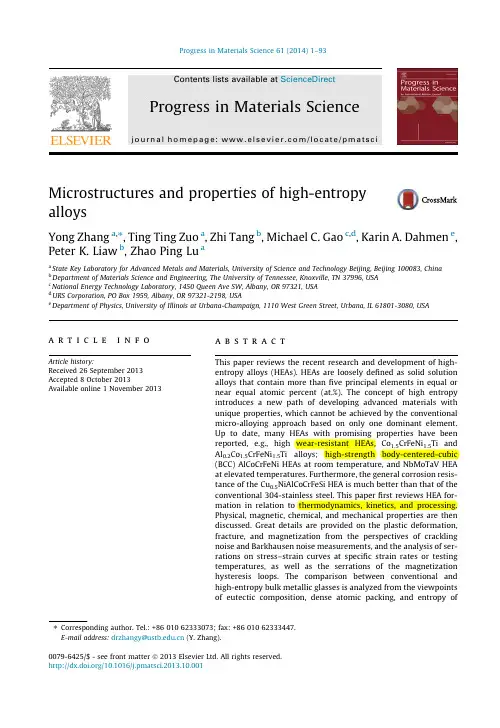
Microstructures and properties of high-entropyalloysYong Zhang a ,⇑,Ting Ting Zuo a ,Zhi Tang b ,Michael C.Gao c ,d ,Karin A.Dahmen e ,Peter K.Liaw b ,Zhao Ping Lu aa State Key Laboratory for Advanced Metals and Materials,University of Science and Technology Beijing,Beijing 100083,Chinab Department of Materials Science and Engineering,The University of Tennessee,Knoxville,TN 37996,USAc National Energy Technology Laboratory,1450Queen Ave SW,Albany,OR 97321,USAd URS Corporation,PO Box 1959,Albany,OR 97321-2198,USAe Department of Physics,University of Illinois at Urbana-Champaign,1110West Green Street,Urbana,IL 61801-3080,USA a r t i c l e i n f o Article history:Received 26September 2013Accepted 8October 2013Available online 1November 2013a b s t r a c tThis paper reviews the recent research and development of high-entropy alloys (HEAs).HEAs are loosely defined as solid solutionalloys that contain more than five principal elements in equal ornear equal atomic percent (at.%).The concept of high entropyintroduces a new path of developing advanced materials withunique properties,which cannot be achieved by the conventionalmicro-alloying approach based on only one dominant element.Up to date,many HEAs with promising properties have beenreported, e.g.,high wear-resistant HEAs,Co 1.5CrFeNi 1.5Ti andAl 0.2Co 1.5CrFeNi 1.5Ti alloys;high-strength body-centered-cubic(BCC)AlCoCrFeNi HEAs at room temperature,and NbMoTaV HEAat elevated temperatures.Furthermore,the general corrosion resis-tance of the Cu 0.5NiAlCoCrFeSi HEA is much better than that of theconventional 304-stainless steel.This paper first reviews HEA for-mation in relation to thermodynamics,kinetics,and processing.Physical,magnetic,chemical,and mechanical properties are thendiscussed.Great details are provided on the plastic deformation,fracture,and magnetization from the perspectives of cracklingnoise and Barkhausen noise measurements,and the analysis of ser-rations on stress–strain curves at specific strain rates or testingtemperatures,as well as the serrations of the magnetizationhysteresis loops.The comparison between conventional andhigh-entropy bulk metallic glasses is analyzed from the viewpointsof eutectic composition,dense atomic packing,and entropy of 0079-6425/$-see front matter Ó2013Elsevier Ltd.All rights reserved./10.1016/j.pmatsci.2013.10.001⇑Corresponding author.Tel.:+8601062333073;fax:+8601062333447.E-mail address:drzhangy@ (Y.Zhang).2Y.Zhang et al./Progress in Materials Science61(2014)1–93mixing.Glass forming ability and plastic properties of high-entropy bulk metallic glasses are also discussed.Modeling tech-niques applicable to HEAs are introduced and discussed,such asab initio molecular dynamics simulations and CALPHAD modeling.Finally,future developments and potential new research directionsfor HEAs are proposed.Ó2013Elsevier Ltd.All rights reserved. Contents1.Introduction (3)1.1.Four core effects (4)1.1.1.High-entropy effect (4)1.1.2.Sluggish diffusion effect (5)1.1.3.Severe lattice-distortion effect (6)1.1.4.Cocktail effect (7)1.2.Key research topics (9)1.2.1.Mechanical properties compared with other alloys (10)1.2.2.Underlying mechanisms for mechanical properties (11)1.2.3.Alloy design and preparation for HEAs (11)1.2.4.Theoretical simulations for HEAs (12)2.Thermodynamics (12)2.1.Entropy (13)2.2.Thermodynamic considerations of phase formation (15)2.3.Microstructures of HEAs (18)3.Kinetics and alloy preparation (23)3.1.Preparation from the liquid state (24)3.2.Preparation from the solid state (29)3.3.Preparation from the gas state (30)3.4.Electrochemical preparation (34)4.Properties (34)4.1.Mechanical behavior (34)4.1.1.Mechanical behavior at room temperature (35)4.1.2.Mechanical behavior at elevated temperatures (38)4.1.3.Mechanical behavior at cryogenic temperatures (45)4.1.4.Fatigue behavior (46)4.1.5.Wear behavior (48)4.1.6.Summary (49)4.2.Physical behavior (50)4.3.Biomedical,chemical and other behaviors (53)5.Serrations and deformation mechanisms (55)5.1.Serrations for HEAs (56)5.2.Barkhausen noise for HEAs (58)5.3.Modeling the Serrations of HEAs (61)5.4.Deformation mechanisms for HEAs (66)6.Glass formation in high-entropy alloys (67)6.1.High-entropy effects on glass formation (67)6.1.1.The best glass former is located at the eutectic compositions (67)6.1.2.The best glass former is the composition with dense atomic packing (67)6.1.3.The best glass former has high entropy of mixing (67)6.2.GFA for HEAs (68)6.3.Properties of high-entropy BMGs (70)7.Modeling and simulations (72)7.1.DFT calculations (73)7.2.AIMD simulations (75)7.3.CALPHAD modeling (80)8.Future development and research (81)Y.Zhang et al./Progress in Materials Science61(2014)1–9338.1.Fundamental understanding of HEAs (82)8.2.Processing and characterization of HEAs (83)8.3.Applications of HEAs (83)9.Summary (84)Disclaimer (85)Acknowledgements (85)References (85)1.IntroductionRecently,high-entropy alloys(HEAs)have attracted increasing attentions because of their unique compositions,microstructures,and adjustable properties[1–31].They are loosely defined as solid solution alloys that contain more thanfive principal elements in equal or near equal atomic percent (at.%)[32].Normally,the atomic fraction of each component is greater than5at.%.The multi-compo-nent equi-molar alloys should be located at the center of a multi-component phase diagram,and their configuration entropy of mixing reaches its maximum(R Ln N;R is the gas constant and N the number of component in the system)for a solution phase.These alloys are defined as HEAs by Yeh et al.[2], and named by Cantor et al.[1,33]as multi-component alloys.Both refer to the same concept.There are also some other names,such as multi-principal-elements alloys,equi-molar alloys,equi-atomic ratio alloys,substitutional alloys,and multi-component alloys.Cantor et al.[1,33]pointed out that a conventional alloy development strategy leads to an enor-mous amount of knowledge about alloys based on one or two components,but little or no knowledge about alloys containing several main components in near-equal proportions.Theoretical and experi-mental works on the occurrence,structure,and properties of crystalline phases have been restricted to alloys based on one or two main components.Thus,the information and understanding are highly developed on alloys close to the corners and edges of a multi-component phase diagram,with much less knowledge about alloys located at the center of the phase diagram,as shown schematically for ternary and quaternary alloy systems in Fig.1.1.This imbalance is significant for ternary alloys but becomes rapidly much more pronounced as the number of components increases.For most quater-nary and other higher-order systems,information about alloys at the center of the phase diagram is virtually nonexistent except those HEA systems that have been reported very recently.In the1990s,researchers began to explore for metallic alloys with super-high glass-forming ability (GFA).Greer[29]proposed a confusion principle,which states that the more elements involved,the lower the chance that the alloy can select viable crystal structures,and thus the greater the chanceand quaternary alloy systems,showing regions of the phase diagram thatand relatively less well known(white)near the center[33].4Y.Zhang et al./Progress in Materials Science61(2014)1–93solid-solutions even though the cooling rate is very high,e.g.,alloys of CuCoNiCrAlFeTiV,FeCrMnNiCo, CoCrFeNiCu,AlCoCrFeNi,NbMoTaWV,etc.[1,2,12–14].The yield strength of the body-centered cubic(BCC)HEAs can be rather high[12],usually compa-rable to BMGs[12].Moreover,the high strength can be kept up to800K or higher for some HEAs based on3d transition metals[14].In contrast,BMGs can only keep their high strength below their glass-transition temperature.1.1.Four core effectsBeing different from the conventional alloys,compositions in HEAs are complex due to the equi-molar concentration of each component.Yeh[37]summarized mainly four core effects for HEAs,that is:(1)Thermodynamics:high-entropy effects;(2)Kinetics:sluggish diffusion;(3)Structures:severe lattice distortion;and(4)Properties:cocktail effects.We will discuss these four core effects separately.1.1.1.High-entropy effectThe high-entropy effects,which tend to stabilize the high-entropy phases,e.g.,solid-solution phases,werefirstly proposed by Yeh[9].The effects were very counterintuitive because it was ex-pected that intermetallic compound phases may form for those equi-or near equi-atomic alloy com-positions which are located at the center of the phase diagrams(for example,a monoclinic compound AlCeCo forms in the center of Al–Ce–Co system[38]).According to the Gibbs phase rule,the number of phases(P)in a given alloy at constant pressure in equilibrium condition is:P¼Cþ1ÀFð1-1Þwhere C is the number of components and F is the maximum number of thermodynamic degrees of freedom in the system.In the case of a6-component system at given pressure,one might expect a maximum of7equilibrium phases at an invariant reaction.However,to our surprise,HEAs form so-lid-solution phases rather than intermetallic phases[1,2,4,17].This is not to say that all multi-compo-nents in equal molar ratio will form solid solution phases at the center of the phase diagram.In fact, only carefully chosen compositions that satisfy the HEA-formation criteria will form solid solutions instead of intermetallic compounds.The solid-solution phase,according to the classical physical-metallurgy theory,is also called a ter-minal solid solution.The solid-solution phase is based on one element,which is called the solvent,and contains other minor elements,which are called the solutes.In HEAs,it is very difficult to differentiate the solvent from the solute because of their equi-molar portions.Many researchers reported that the multi-principal-element alloys can only form simple phases of body-centered-cubic(BCC)or face-cen-tered-cubic(FCC)solid solutions,and the number of phases formed is much fewer than the maximum number of phases that the Gibbs phase rule allows[9,23].This feature also indicates that the high en-tropy of the alloys tends to expand the solution limits between the elements,which may further con-firm the high-entropy effects.The high-entropy effect is mainly used to explain the multi-principal-element solid solution. According to the maximum entropy production principle(MEPP)[39],high entropy tends to stabilize the high-entropy phases,i.e.,solid-solution phases,rather than intermetallic phases.Intermetallics are usually ordered phases with lower configurational entropy.For stoichiometric intermetallic com-pounds,their configurational entropy is zero.Whether a HEA of single solid solution phase is in its equilibrium has been questioned in the sci-entific community.There have been accumulated evidences to show that the high entropy of mixing truly extends the solubility limits of solid solution.For example,Lucas et al.[40]recently reported ab-sence of long-range chemical ordering in equi-molar FeCoCrNi alloy that forms a disordered FCC struc-ture.On the other hand,it was reported that some equi-atomic compositions such as AlCoCrCuFeNi contain several phases of different compositions when cooling slowly from the melt[15],and thus it is controversial whether they can be still classified as HEA.The empirical rules in guiding HEA for-mation are addressed in Section2,which includes atomic size difference and heat of mixing.Y.Zhang et al./Progress in Materials Science61(2014)1–935 1.1.2.Sluggish diffusion effectThe sluggish diffusion effect here is compared with that of the conventional alloys rather than the bulk-glass-forming alloys.Recently,Yeh[9]studied the vacancy formation and the composition par-tition in HEAs,and compared the diffusion coefficients for the elements in pure metals,stainless steels, and HEAs,and found that the order of diffusion rates in the three types of alloy systems is shown be-low:Microstructures of an as-cast CuCoNiCrAlFe alloy.(A)SEM micrograph of an etched alloy withBCC and ordered BCC phases)and interdendrite(an FCC phase)structures.(B)TEMplate,70-nm wide,a disordered BCC phase(A2),lattice constant,2.89A;(B-b)aphase(B2),lattice constant,2.89A;(B-c)nanoprecipitation in a spinodal plate,7nm(B-d)nanoprecipitation in an interspinodal plate,3nm in diameter,a disorderedarea diffraction(SAD)patterns of B,Ba,and Bb with zone axes of BCC[01[011],respectively[2].illustration of intrinsic lattice distortion effects on Bragg diffraction:(a)perfect latticewith solid solutions of different-sized atoms,which are expected to randomly distribute statistical average probability of occupancy;(c)temperature and distortion effectsY.Zhang et al./Progress in Materials Science61(2014)1–937 the intensities further drop beyond the thermal effect with increasing the number of constituent prin-cipal elements.An intrinsic lattice distortion effect caused by the addition of multi-principal elements with different atomic sizes is expected for the anomalous decrease in the XRD intensities.The math-ematical treatment of this distortion effect for the modification of the XRD structure factor is formu-lated to be similar to that of the thermal effect,as shown in Fig.1.3[41].The larger roughness of the atomic planes makes the intensity of the XRD for HEAs much lower than that for the single-element solid.The severe lattice distortion is also used to explain the high strength of HEAs,especially the BCC-structured HEAs[4,12,23].The severe lattice-distortion effect is also related to the tensileFCC-structured HEAs have very low strength[7],which certainly cannot be explained by thelattice distortion argument.Fundamental studies in quantification of lattice distortion of HEAs are needed.1.1.4.Cocktail effectThe cocktail-party effect was usually used as a term in the acousticsfield,which have been used to describe the ability to focus one’s listening attention on a single talker among a mixture of conversa-tions and background noises,ignoring other conversations.For metallic alloys,the effect indicates that the unexpected properties can be obtained after mixing many elements,which could not be obtained from any one independent element.The cocktail effect for metallic alloys wasfirst mentioned by Ranganathan[42],which has been subsequently confirmed in the mechanical and physical properties [12,13,15,18,35,43].The cocktail effect implies that the alloy properties can be greatly adjusted by the composition change and alloying,as shown in Fig.1.4,which indicates that the hardness of HEAs can be dramat-ically changed by adjusting the Al content in the CoCrCuNiAl x HEAs.With the increase of the Al con-lattice constants of a CuCoNiCrAl x Fe alloy system with different x values:(A)hardnessconstants of an FCC phase,(C)lattice constants of a BCC phase[2].CoNiCrAl x Fe alloy system with different x values,the Cu-free alloy has lower hardness.CoCrCuFeNiAl x[15,45].Cu forms isomorphous solid solution with Ni but it is insoluble in Co,Cr and Fe;it dissolves about20at.%Al but also forms various stable intermetallic compounds with Al.Fig.1.6exhibits the hardness of some reported HEAs in the descending order with stainless steels as benchmark.The MoTiVFeNiZrCoCr alloy has a very high value of hardness of over800HV while CoCrFeNiCu is very soft with a value of less than200HV.Fig.1.7compares the specific strength,which yield strength over the density of the materials,and the density amongalloys,polymers and foam materials[5].We can see that HEAs have densitieshigh values of specific strength(yield strength/density).This is partiallyHEAs usually contain mainly the late transitional elements whoselightweight HEAs have much more potential because lightweightdensity of the resultant alloys will be lowered significantly.Fig.1.8strength of HEAs vs.Young’s modulus compared with conventional alloys.highest specific strength and their Young’s modulus can be variedrange of hardness for HEAs,compared with17–4PH stainless steel,Hastelloy,andYield strength,r y,vs.density,q.HEAs(dark dashed circle)compared with other materials,particularly structural Grey dashed contours(arrow indication)label the specific strength,r y/q,from low(right bottom)to high(left top).among the materials with highest strength and specific strength[5].Specific-yield strength vs.Young’s modulus:HEAs compared with other materials,particularly structural alloys.among the materials with highest specific strength and with a wide range of Young’s modulus[5].range.This observation may indicate that the modulus of HEAs can be more easily adjusted than con-ventional alloys.In addition to the high specific strength,other properties such as high hydrogen stor-age property are also reported[46].1.2.Key research topicsTo understand the fundamentals of HEAs is a challenge to the scientists in materials science and relatedfields because of lack of thermodynamic and kinetic data for multi-component systems in the center of phase diagrams.The phase diagrams are usually available only for the binary and ternary alloys.For HEAs,no complete phase diagrams are currently available to directly assist designing thealloy with desirable micro-and nanostructures.Recently,Yang and Zhang [28]proposed the Xparam-eter to design the solid-solution phase HEAs,which should be used combing with the parameter of atomic-size difference.This strategy may provide a starting point prior to actual experiments.The plastic deformation and fracture mechanisms of HEAs are also new because the high-entropy solid solutions contain high contents of multi-principal elements.In single principal-element alloys,dislo-cations dominate the plastic behavior.However,how dislocations interact with highly-disordered crystal lattices and/or chemical disordering/ordering will be an important factor responsible for plastic properties of HEAs.Interactions between the other crystal defects,such as twinning and stacking faults,with chemical/crystal disordering/ordering in HEAs will be important as well.1.2.1.Mechanical properties compared with other alloysFor conventional alloys that contain a single principal element,the main mechanical behavior is dictated by the dominant element.The other minor alloying elements are used to enhance some spe-cial properties.For example,in the low-carbon ferritic steels [47–59],the main mechanical properties are from the BCC Fe.Carbon,which is an interstitial solute element,is used for solid-solution strength-ened steels,and also to enhance the martensite-quenching ability which is the phase-transformation strengthening.The main properties of steels are still from Fe.For aluminum alloys [60]and titanium alloys [61],their properties are mainly related to the dominance of the elemental aluminum and tita-nium,respectively.Intermetallic compounds are usually based on two elements,e.g.,Ti–Al,Fe 3Al,and Fe 3Si.Interme-tallic compounds are typically ordered phases and some may have strict compositional range.The Burgers vectors of the ordered phases are too large for the dislocations to move,which is the main reason why intermetallic phases are usually brittle.However,there are many successful case studies to improve the ductility of intermetallic compound by micro-alloying,e.g.,micro-alloying of B in Ni 3Al[62],and micro-alloying of Cr in Fe 3Al [63,64].Amorphous metals usually contain at least three elements although binary metallic glasses are also reported,and higher GFA can be obtained with addition of more elements,e.g.,ZrTiCuNiBe (Vit-1),PdNiCuP,LaAlNiCu,and CuZrAlY alloys [65–69].Amorphous metals usually exhibit ultrahigh yield strength,because they do not contain conventional any weakening factors,such as dislocations and grain boundaries,and their yield strengths are usually three to five times of their corresponding crys-talline counterpart alloys.There are several models that are proposed to explain the plastic deforma-tion of the amorphous metal,including the free volume [70],a shear-transformation-zone (STZ)[71],more recently a tension-transition zone (TTZ)[72],and the atomic-level stress [73,74].The micro-mechanisms of the plastic deformation of amorphous metals are usually by forming shear bands,which is still an active research area till today.However,the high strength of amorphous alloys can be sustained only below the glass-transition temperature (T g ).At temperatures immediately above T g ,the amorphous metals will transit to be viscous liquids [68]and will crystallize at temperatures above the first crystallization onset temperature.This trend may limit the high-temperature applica-tions of amorphous metals.The glass forming alloys often are chemically located close to the eutectic composition,which further facilitates the formation of the amorphous metal–matrix composite.The development of the amorphous metal–matrix composite can enhance the room-temperature plastic-ity of amorphous metals,and extend application temperatures [75–78].For HEAs,their properties can be different from any of the constituent elements.The structure types are the dominant factor for controlling the strength or hardness of HEAs [5,12,13].The BCC-structured HEAs usually have very high yield strengths and limited plasticity,while the FCC-structured HEAs have low yield strength and high plasticity.The mixture of BCC +FCC is expected to possess balanced mechanical properties,e.g.,both high strength and good ductility.Recent studies show that the microstructures of certain ‘‘HEAs’’can be very complicated since they often undergo the spinodal decomposition,and ordered,and disordered phase precipitates at lower temperatures.Solution-strengthening mechanisms for HEAs would be much different from conventional alloys.HEAs usually have high melting points,and the high yield strength can usually be sustained to ultrahigh temperatures,which is shown in Fig.1.9for refractory metal HEAs.The strength of HEAs are sometimes better than those of conventional superalloys [14].10Y.Zhang et al./Progress in Materials Science 61(2014)1–931.2.2.Underlying mechanisms for mechanical propertiesMechanical properties include the Young’s modulus,yield strength,plastic elongation,fracture toughness,and fatigue properties.For the conventional one-element principal alloys,the Young’s modulus is mainly controlled by the dominant element,e.g.,the Young’s modulus of Fe-based alloys is about 200GPa,that of Ti-based alloys is approximately 110GPa,and that of Al-based alloys is about 75GPa,as shown in Fig.1.8.In contrast,for HEAs,the modulus can be very different from any of the constituent elements in the alloys [79],and the moduli of HEAs are scattered in a wide range,as shown in Fig.1.8.Wang et al.[79]reported that the Young’s modulus of the CoCrFeNiCuAl 0.5HEA is about 24.5GPa,which is much lower than the modulus of any of the constituent elements in the alloy.It is even lower than the Young’s modulus of pure Al,about 69GPa [80].On the other hand,this value needs to be verified using other methods including impulse excitation of vibration.It has been reported that the FCC-structured HEAs exhibit low strength and high plasticity [13],while the BCC-structured HEAs show high strength and low plasticity at room temperature [12].Thus,the structure types are the dominant factor for controlling the strength or hardness of HEAs.For the fracture toughness of the HEAs,there is no report up to date.1.2.3.Alloy design and preparation for HEAsIt has been verified that not all the alloys with five-principal elements and with equi-atomic ratio compositions can form HEA solid solutions.Only carefully chosen compositions can form FCC and BCC solid solutions.Till today there is no report on hexagonal close-packed (HCP)-structured HEAs.One reason is probably due to the fact that a HCP structure is often the stable structure at low tempera-tures for pure elements (applicable)in the periodic table,and that it may transform to either BCC or FCC at high temperatures.Most of the HEA solid solutions are identified by trial-and-error exper-iments because there is no phase diagram on quaternary and higher systems.Hence,the trial-and er-ror approach is the main way to develop high-performance HEAs.However,some parameters have been proposed to predict the phase formation of HEAs [17,22,28]in analogy to the Hume-Rothery rule for conventional solid solution.The fundamental thermodynamic equation states:G ¼H ÀTS ð1-2Þwhere H is the enthalpy,S is the entropy,G is the Gibbs free energy,and T is the absolute temperature.From Eq.(1-2),the TS term will become significant at high temperatures.Hence,preparing HEAs from the liquid and gas would provide different kinds of information.These techniques may include sput-Temperature dependence of NbMoTaW,VNbMoTaW,Inconel 718,and Haynes 230tering,laser cladding,plasma coating,and arc melting,which will be discussed in detail in the next chapter.For the atomic-level structures of HEAs,the neutron and synchrotron diffraction methods are useful to detect ordering parameters,long-range order,and short-range ordering[81].1.2.4.Theoretical simulations for HEAsFor HEAs,entropy effects are the core to their formation and properties.Some immediate questions are:(1)How can we accurately predict the total entropy of HEA phase?(2)How can we predict the phasefield of a HEA phase as a function of compositions and temperatures?(3)What are the proper modeling and experimental methods to study HEAs?To address the phase-stability issue,thermody-namic modeling is necessary as thefirst step to understand the fundamental of HEAs.The typical mod-eling techniques to address thermodynamics include the calculation of phase diagram(CALPHAD) modeling,first-principle calculations,molecular-dynamics(MD)simulations,and Monte Carlo simulations.Kao et al.[82]using MD to study the structure of HEAs,and their modeling efforts can well explain the liquid-like structure of HEAs,as shown in Fig.1.10.Grosso et al.[83]studied refractory HEAs using atomistic modeling,clarified the role of each element and their interactions,and concluded that4-and 5-elements alloys are possible to quantify the transition to a high-entropy regime characterized by the formation of a continuous solid solution.2.Thermodynamicsof a liquid-like atomic-packing structure using multiple elementsthird,fourth,andfifth shells,respectively,but the second and third shellsdifference and thus the largefluctuation in occupation of different atoms.2.1.EntropyEntropy is a thermodynamic property that can be used to determine the energy available for the useful work in a thermodynamic process,such as in energy-conversion devices,engines,or machines. The following equation is the definition of entropy:dS¼D QTð2-1Þwhere S is the entropy,Q is the heatflow,and T is the absolute temperature.Thermodynamic entropy has the dimension of energy divided by temperature,and a unit of Joules per Kelvin(J/K)in the Inter-national System of Units.The statistical-mechanics definition of entropy was developed by Ludwig Boltzmann in the1870s [85]and by analyzing the statistical behavior of the microscopic components of the system[86].Boltz-mann’s hypothesis states that the entropy of a system is linearly related to the logarithm of the fre-quency of occurrence of a macro-state or,more precisely,the number,W,of possible micro-states corresponding to the macroscopic state of a system:Fig.2.1.Illustration of the D S mix for ternary alloy system with the composition change[17].。

第 1 期第 200-210 页材料工程Vol.52Jan. 2024Journal of Materials EngineeringNo.1pp.200-210第 52 卷2024 年 1 月TiVNbTa/Inconel 600扩散焊接头的组织与性能Microstructure and properties of TiVNbTa/Inconel 600 diffusionwelded joint李娟1,沈宽春2,尹蓉1,赵宏龙1,罗少敏1,周念1,秦庆东1*(1 贵州理工学院 贵州省轻金属材料制备技术重点实验室,贵阳550003;2 中航工业贵州永红航空机械有限责任公司,贵阳550009)LI Juan 1,SHEN Kuanchun 2,YIN Rong 1,ZHAO Honglong 1,LUO Shaomin 1,ZHOU Nian 1,QIN Qingdong 1*(1 Key Laboratory of Light Metal Materials Processing Technology of Guizhou Province ,Guizhou Institute of Technology ,Guiyang 550003,China ;2 AVIC Guizhou Yonghong Aviation MachineryCo.,Ltd., Guiyang 550009,China )摘要:鉴于TiVNbTa 难熔高熵合金优异的耐蚀性和高温强度,针对其与高温合金复合使用的潜在应用前景,研究TiVNbTa 和Inconel 600的扩散焊接性能。
在850~1150 ℃条件下对二者进行了扩散焊研究,对850~1000 ℃下所得接头的微观组织进行了观察,对所有温度下所得接头的剪切强度进行了检测。
研究结果表明,除850 ℃下所得接头只含一层富Ni 界面层外,其余接头均具有“Inconel 600/镍基扩散层/富Cr 层/富Ti 层/富Ni 层/TiVNbTaNi (Fe ,Cr )扩散层/TiVNbTa RHEA ”多层界面结构,其中富Ni 层为具有菱方晶体结构的Ni 2Ti 型金属间化合物,富Cr 层为具有密排六方晶体结构的Cr 2X 型Laves 金属间化合物。
高温超导材料樊世敏摘要自从1911年发现超导材料以来,先后经历了简单金属、合金,再到复杂化合物,超导转变温度也逐渐提高,目前,已经提高到164K(高压状态下)。
本文主要介绍高温超导材料中的其中三类:钇系(YBCO)、铋系(BSCCO)和二硼化镁(MgB2),以及高温超导材料的应用。
与目前主要应用领域相结合,对高温超导材料的发展方向提出展望。
关键词高温超导材料,超导特性,高温超导应用1 引言超导材料的发现和发展已经有将近百年的历史,前期超导材料的温度一直处于低温领域,发展缓慢。
直到1986年,高温超导(HTS)材料的发现,才进一步激发了研究高温超导材料的热潮。
经过20多年的发展,已经形成工艺成熟的第一代HTS带材—-BSCCO带材,目前正在研发第二代HTS带材-—YBCO涂层导体,近一步强化了HTS带材在强电领域中的应用。
与此同时,HTS薄膜和HTS块材的制备工艺也在不断地发展和完善,前者己经在强电领域得到了很好的应用,后者则在弱电领域中得到应用,并且有着非常广阔的应用前景.2 高温超导体的发现简史20世纪初,荷兰莱顿实验室科学家卡默林昂尼斯(H K Onnes)等人的不断努力下,将氦气液化[1-7],在随后的1911年,昂尼斯等人测量了金属汞的低温电阻,发现了超导电性这一特殊的物理现象.引起了科学家对超导材料的研究热潮。
从1911到1932年间,以研究元素超导为主,除汞以外,又发现了Pb、Sn、Nb等众多的金属元素超导体;从1932到1953年间,则发现了许多具有超导电性的合金,以及NaCl结构的过渡金属碳化合物和氮化物,临界转变温度(Tc)得到了进一步提高;随后,在1953到1973年间,发现了Tc大于17K的Nb3Sn等超导体.直到1986年,美国国际商用机器公司在瑞士苏黎世实验室的科学家柏诺兹(J。
G。
Bednorz)和缪勒(K。
A。
Müller)首先制备出了Tc为35K的镧—钡—铜—氧(La—Ba—Cu-O)高温氧化物超导体,高温超导材料的研究才取得了重大突破[10,11]。
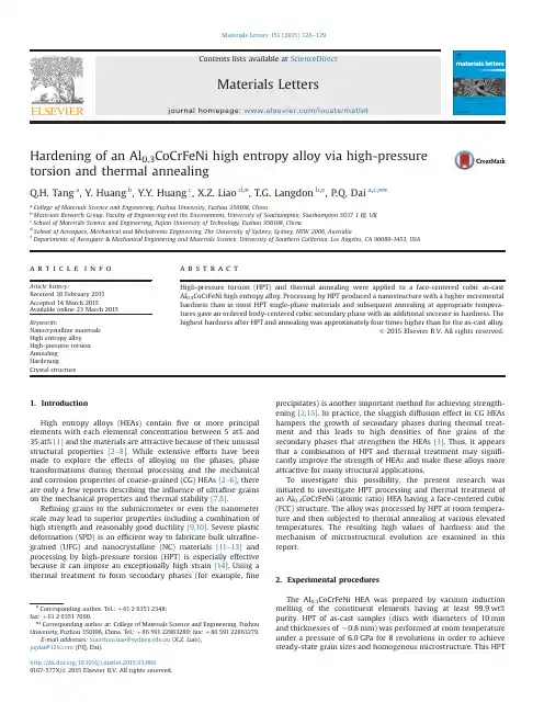
Hardening of an Al0.3CoCrFeNi high entropy alloy via high-pressuretorsion and thermal annealingQ.H.Tang a,Y.Huang b,Y.Y.Huang c,X.Z.Liao d,n,ngdon b,e,P.Q.Dai a,c,nna College of Materials Science and Engineering,Fuzhou University,Fuzhou350108,Chinab Materials Research Group,Faculty of Engineering and the Environment,University of Southampton,Southampton SO171BJ,UKc School of Materials Science and Engineering,Fujian University of Technology,Fuzhou350108,Chinad School of Aerospace,Mechanical and Mechatronic Engineering,The University of Sydney,Sydney,NSW2006,Australiae Departments of Aerospace&Mechanical Engineering and Materials Science,University of Southern California,Los Angeles,CA90089-1453,USAa r t i c l e i n f oArticle history:Received10February2015Accepted14March2015Available online23March2015Keywords:Nanocrystalline materialsHigh entropy alloyHigh-pressure torsionAnnealingHardeningCrystal structurea b s t r a c tHigh-pressure torsion(HPT)and thermal annealing were applied to a face-centered cubic as-castAl0.3CoCrFeNi high entropy alloy.Processing by HPT produced a nanostructure with a higher incrementalhardness than in most HPT single-phase materials and subsequent annealing at appropriate tempera-tures gave an ordered body-centered cubic secondary phase with an additional increase in hardness.Thehighest hardness after HPT and annealing was approximately four times higher than for the as-cast alloy.&2015Elsevier B.V.All rights reserved.1.IntroductionHigh entropy alloys(HEAs)containfive or more principalelements with each elemental concentration between5at%and35at%[1]and the materials are attractive because of their unusualstructural properties[2–8].While extensive efforts have beenmade to explore the effects of alloying on the phases,phasetransformations during thermal processing and the mechanicaland corrosion properties of coarse-grained(CG)HEAs[2–6],thereare only a few reports describing the influence of ultrafine grainson the mechanical properties and thermal stability[7,8].Refining grains to the submicrometer or even the nanometerscale may lead to superior properties including a combination ofhigh strength and reasonably good ductility[9,10].Severe plasticdeformation(SPD)is an efficient way to fabricate bulk ultrafine-grained(UFG)and nanocrystalline(NC)materials[11–13]andprocessing by high-pressure torsion(HPT)is especially effectivebecause it can impose an exceptionally high strain[14].Using athermal treatment to form secondary phases(for example,fineprecipitates)is another important method for achieving strength-ening[2,15].In practice,the sluggish diffusion effect in CG HEAshampers the growth of secondary phases during thermal treat-ment and this leads to high densities offine grains of thesecondary phases that strengthen the HEAs[3].Thus,it appearsthat a combination of HPT and thermal treatment may signifi-cantly improve the strength of HEAs and make these alloys moreattractive for many structural applications.To investigate this possibility,the present research wasinitiated to investigate HPT processing and thermal treatment ofan Al0.3CoCrFeNi(atomic ratio)HEA having a face-centered cubic(FCC)structure.The alloy was processed by HPT at room tempera-ture and then subjected to thermal annealing at various elevatedtemperatures.The resulting high values of hardness and themechanism of microstructural evolution are examined in thisreport.2.Experimental proceduresThe Al0.3CoCrFeNi HEA was prepared by vacuum inductionmelting of the constituent elements having at least99.9wt%purity.HPT of as-cast samples(discs with diameters of10mmand thicknesses of$0.8mm)was performed at room temperatureunder a pressure of6.0GPa for8revolutions in order to achievesteady-state grain sizes and homogenous microstructure.This HPTContents lists available at ScienceDirectjournal homepage:/locate/matletMaterials Letters/10.1016/j.matlet.2015.03.0660167-577X/&2015Elsevier B.V.All rightsreserved.n Corresponding author.Tel.:þ61293512348;fax:þ61293517060.nn Corresponding author at:College of Materials Science and Engineering,FuzhouUniversity,Fuzhou350108,China.Tel.:þ8659122863280;fax:þ8659122863279.E-mail addresses:xiaozhou.liao@.au(X.Z.Liao),pqdai@(P.Q.Dai).Materials Letters151(2015)126–129HEA is designated NC-RT denoting nanocrystalline at room tem-perature.Specimens with diameters of3mm were cut from the HPT disc edges for further thermal processing.Thermal annealing was performed at temperatures of573,673,773,873and973K for 1h;these HEA samples are referred to as NC-573,NC-673,NC-773, NC-873and NC-973.For comparison,the CG as-cast samples were also annealed at these temperatures.The hardness was measured using a DHV-1000Vickers micro-hardness tester with a load of200g and a dwell time of15s.X-ray diffraction(XRD)was conducted using a Bruker D8Advance diffractometer equipped with a Cu target.The dislocation density,ρ;was estimated from the XRD patterns using the relationship[16]ρ¼2ffiffiffi3p oε241=2=db,where d is crystallite size,oε241=2is microstrain,and b is the absolute value of the Burgers vector of 1=2o1104for FCC metals.Transmission electron microscopy (TEM)observations were performed using a JEM-2100microscope operating at200kV.The average grain sizes were estimated by measuring at least200grains along two orthogonal axes from the TEM images.3.Results and discussionFig.1shows the Vickers hardness of the as-cast and HPT HEA before and after annealing.The as-cast HEA,having a typical CG structure with grain sizes ranging from$100to$1100μm (average$350μm),had a hardness of$150.After HPT,the hardness increased to$530.This incremental increase in hard-ness of$380converts to an increase of$3.7GPa which is higher than the HPT-induced hardness increments of most single-phase materials where the increases are generally lower than$3.1GPa: a summary of these numbers is given by Edalati et al.[17].For conventional single-phase alloy systems,introducing solute atoms can enhance solid-solution hardening and produce greater grain refinement compared to pure metals[17].Since all principal elements acting as solute atoms were introduced to HEAs[1,3], it is reasonable to anticipate that HEAs should have a strong potential for strengthening via SPD.This is readily proven by the experimental data in Fig.1.Annealing at different temperatures showed different effects on the Vickers hardness of the HPT HEA.Therefore,the annealing temperature range was divided into three regions(Fig.1).Anneal-ing up to573K in region I produces no change in hardness but increasing the annealing temperature to773K in region II leads to increased hardness and a peak value of$615which is$4times higher than the hardness of the as-cast HEA and should be more than4times higher than the hardness of the single-crystal HEA reported in Ref.[4].Further increasing the annealing temperature to region III reduces the hardness.The results demonstrate that a combination of HPT and annealing at appropriate temperatures is an effective method for strengthening HEAs.By comparison,the effect of annealing on the hardness of the as-cast HEA shows a similar trend but the hardness starts to increase at a higher temperature of773K(Fig.1).Fig.2shows XRD patterns of HPT HEA before and after annealing.Only the FCC phase was detected when annealing at or below573K.At673and773K,new peaks appear at2θE301 and2θE451and they are identified as100and110diffraction ofthe ordered body-centered cubic(BCC)phase[5].The100peak reaches its highest intensity at773K suggesting an increase in the amount of the ordered BCC phase at least until773K.The100 peak disappears at higher temperatures and this is probably caused by the variation of preferred orientation of the ordered BCC phase because the remaining110peak confirms the ordered BCC phase.The XRD data suggest the coexistence of two phases at or above673K.Fig.3shows the microstructure of the HPT HEA after annealing in different temperature regions.Nanotwins were seen only occasionally and therefore its effect on mechanical behavior of the HPT samples should be negligible.In region I,nanoscale equiaxed grains with ill-defined grain boundaries(GBs)were observed(Fig.3a).This type of GB structure is non-equilibrium due to the presence of non-geometrically necessary dislocations at the GBs[11].In region II,the GBs became sharp and well-defined (Fig.3b).This change in GB morphology is associated with dislocation annihilation.Fig.3c shows the formation of an ordered BCC secondary phase in the vicinity of the matrix GBs,as evidenced by the Fourier transformation at the top-left inset.In region III,grain growth clearly occurs for both the matrix and the secondary phase(see Fig.3d and Table1)and the selected-area electron diffraction(SAED)patterns(insets in Fig.3d)confirm the coexistence of the FCC matrix and the ordered BCC secondary phase.An electron energy dispersive spectroscopy(EDS)analysis (results shown in Fig.3d)reveals that the secondary phase contains more Al and Ni than in the matrix.A similar Al-and Ni-rich ordered BCC phase was reported in some CG Al-contained HEA systems[2,15]and the ordered BCC phase is more brittle and stronger than the FCC matrix[5].Table1lists the dislocation densities and lattice parameters obtained from the XRD analysis and average grain sizes fromtheFig.1.The dependence of Vickers hardness of the as-cast and HPT HEA on theannealingtemperature.Fig.2.XRD patterns of the HPT HEA before and after annealing.Q.H.Tang et al./Materials Letters151(2015)126–129127TEM measurements.The dislocation density decreases monoto-nously with increasing annealing temperature and this is respon-sible for the formation of well-de fined GBs in region II.The evolution of lattice parameters re flects the change in the composi-tions of the two phases.At or below 573K,the lattice parameter of the FCC phase remains almost constant indicating an absence of elemental diffusion.At 673K and above,the lattice parameter of the FCC phase first decreases and then stabilizes while that of the ordered BCC phase shows an opposite trend.These evolutions are due to a partitioning of Al from the FCC phase to the ordered BCC phase.No major grain growth is observed in region I but there is a minor increase in the grain sizes of the two phases in region II and very signi ficant growth in region III.The results show that grain re finement plays a most important role for the hardness increment since it contributes $82%of the increment after HPT and annealing at 773K.The contribution of the dislocation density to the hardness is almost negligible for the nanocrystalline alloy since a reduction of $42%in the dislocation density after annealing at 573K gave no signi ficant change in the hardness.The formation of the hard ordered BCC phase contri-butes $18%of the total hardness increment at 773K.The slightincrease in grain size at this temperature appears to have only a minor effect on the hardness.As annealing temperature increases above 773K,the signi ficant grain growth in both the FCC and the ordered BCC phases becomes more predominantly responsible for an overall hardness reduction because of the Hall –Petch effect.4.Summary and conclusionsThe results demonstrate that a combination of HPT processing and thermal annealing signi ficantly strengthens the hardness of an Al 0.3CoCrFeNi HEA.The highest hardness achieved is about 4times larger than the original hardness of the as-cast HEA.Mechanical testing and structural characterization shows that most of this incremental increase in hardness is due to grain re finement to the nanometer range.The formation of a hard secondary phase during thermal annealing,where this is Al-and Ni-rich and of an ordered BCC structure,further increases the hardness.AcknowledgmentsQHT and PQD appreciate the scienti fic fund of the Fujian University of Technology (No.E0600133).XZL thanks the Austra-lian Research Council for financial support (No.DP150101121).This work was supported in part by the European Research Council under ERC Grant Agreement no.267464-SPDMETALS (YH and TGL).References[1]Yeh JW,Chen SK,Lin SJ,Gan JY,Chin TS,Shun TT,et al.Adv Eng Mater2004;6:299–303.[2]Chen ST,Tang WY,Kuo YF,Chen SY,Tsau CH,Shun TT,et al.Mater Sci Eng A2010;527:5818–25.Fig.3.TEM images taken from:(a)a NC –RT;(b)a NC-773;(c)a high-resolution image also from a NC-773.A white square indicates an area where secondary phase formed and Fourier transformation responded to;(d)a NC-973.Two circles indicate the places where EDS data and SAED patterns were obtained.Table 1The calculated dislocation density (ρ),the lattice parameters of the FCC and ordered BCC phases (a FCC and a BCC ),and the average grain sizes (d FCC and d BCC )of the HPT HEA before and after annealing.SamplesRegion I Region II Region III NC –RTNC-573NC-673NC-773NC-873NC-973ρ(m À2) 1.1Â1015 6.4Â1014 3.8Â10147Â10133Â10131Â1013a FCC (nm)0.35950.35960.35930.35830.35790.3580a BCC (nm)––0.28360.28440.28700.2871d FCC (nm)3030334090280a bCC (nm)––8103060Q.H.Tang et al./Materials Letters 151(2015)126–129128[3]Zhang Y,Zuo TT,Tang Z,Gao MC,Dahmen KA,Liaw PK.Prog Mater Sci2014;61:1–93.[4]Ma SG,Zhang SF,Qiao JW,Wang ZH,Gao MC,Jiao ZM,et al.Intermetallics2014;54:104–9.[5]He JY,Liu WH,Wang H,Wu Y,Liu XJ,Nieh TG,et al.Acta Mater2014;62:105–13.[6]Ma SG,Zhang SF,Gao MC,Liaw PK,Zhang Y.J Miner Metals Mater Soc2013;65:1751–8.[7]Romankov S,Park YC,Shchetinin IV,Yoon JM.Acta Mater2013;61:1254–65.[8]Varalakshmi S,Kamaraj M,Murty BS.Mater Sci Eng A2010;527:1027–30.[9]Valiev RZ,Islamgaliev RK,Alexandrov IV.Prog Mater Sci2000;45:103–89.[10]Meyers MA,Mishra A,Benson DJ.Prog Mater Sci2006;51:427–556.[11]Zhao YH,Liao XZ,Jin Z,Valiev RZ,Zhu YT.Acta Mater2004;52:4589–99.[12]Eivani AR.Mater Lett2015;139:15–8.[13]Langdon TG.Acta Mater2013;61:7035–59.[14]Zhilyaev AP,Langdon TG.Prog Mater Sci2008;53:893–979.[15]Shun TT,Du YC.J Alloy Compd2009;479:157–60.[16]Williamson GK,Smallman RE.Philos Mag1956;1:34–6.[17]Edalati K,Akama D,Nishio A,Lee S,Yonenaga Y,Cubero-Sesin JM,et al.ActaMater2014;69:68–77.Q.H.Tang et al./Materials Letters151(2015)126–129129。

DOI: 10.1126/science.1254581, 1153 (2014);345 Science et al.Bernd Gludovatz A fracture-resistant high-entropy alloy for cryogenic applicationsThis copy is for your personal, non-commercial use only.clicking here.colleagues, clients, or customers by , you can order high-quality copies for your If you wish to distribute this article to othershere.following the guidelines can be obtained by Permission to republish or repurpose articles or portions of articles): September 13, 2014 (this information is current as of The following resources related to this article are available online at/content/345/6201/1153.full.html version of this article at:including high-resolution figures, can be found in the online Updated information and services, /content/suppl/2014/09/03/345.6201.1153.DC1.html can be found at:Supporting Online Material /content/345/6201/1153.full.html#ref-list-1, 2 of which can be accessed free:cites 45 articles This article/cgi/collection/mat_sci Materials Sciencesubject collections:This article appears in the following registered trademark of AAAS.is a Science 2014 by the American Association for the Advancement of Science; all rights reserved. The title Copyright American Association for the Advancement of Science, 1200 New York Avenue NW, Washington, DC 20005. (print ISSN 0036-8075; online ISSN 1095-9203) is published weekly, except the last week in December, by the Science o n S e p t e m b e r 13, 2014w w w .s c i e n c e m a g .o r g D o w n l o a d e d f r o mdid not observe the formation of any well-defined structures in the absence of an applied magnetic field (see,e.g.,fig.S8J).24.A.Dong et al .,Nano Lett.11,841–846(2011).25.S.Brooks,A.Gelman,G.Jones,X.-L.Meng,Handbook of Markov Chain Monte Carlo (Chapman &Hall,London,2011).26.Z.Kakol,R.N.Pribble,J.M.Honig,Solid State Commun.69,793–796(1989).27.Ü.Özgür,Y.Alivov,H.Morkoç,J.Mater.Sci.Mater.Electron.20,789–834(2009).28.The formation of helices,and the self-assembly of NCs in our system in general,is likely facilitated by entropic forces;OA used in large excess during self-assembly may act as adepletion agent,inducing crystallization of NCs during hexane evaporation as reported previously (29).29.D.Baranov et al .,Nano Lett.10,743–749(2010).30.On the basis of measurements of electrophoretic mobility [see (34)]and the lack of literature reports on electric dipole moments of magnetite nanoparticles,we did not considerelectrostatic and electric dipole-dipole interactions in our analysis of interparticle interactions.At the same time,we cannot exclude 31.S.Srivastava et al .,Science 327,1355–1359(2010).32.S.Das et al .,Adv.Mater.25,422–426(2013).33.J.V.I.Timonen,tikka,L.Leibler,R.H.A.Ras,O.Ikkala,Science 341,253–257(2013).34.Previous self-assembly experiments performed in nonpolarsolvents excluded a significant role played by electrostatic interactions [e.g.,(35,36)].Although the degree ofdissociation of OA in hexane (dielectric constant =1.84)is negligible,the large excess of OA as well as the nature of our experimental setup (self-assembly at the liquid-air interface)might potentially promote dissociation of OA;to verify this possibility,we used a Malvern Zetasizer Nano ZS to perform electrophoretic mobility (m e )measurements of our nanocubes in hexane both in the absence and in the presence of additional OA (5%v/v).The results [0.00706(T 0.00104)×10−4cm 2V –1s –1and 0.0218(T 0.00710)×10−4cm 2V –1s –1,respectively]indicate that in both cases,the nanocubes are essentially neutral [compare with (37)].35.Z.Chen,J.Moore,G.Radtke,H.Sirringhaus,S.O ’Brien,J.Am.Chem.Soc.129,15702–15709(2007).37.S.A.Hasan,D.W.Kavich,J.H.Dickerson,mun.2009,3723–3725(2009).ACKNOWLEDGMENTSSupported by Israel Science Foundation grant 1463/11,theG.M.J.Schmidt-Minerva Center for Supramolecular Architectures,and the Minerva Foundation with funding from the Federal German Ministry for Education and Research (R.K.)and byNSF Division of Materials Research grant 1309765and American Chemical Society Petroleum Research Fund grant 53062-ND6(P.K.).SUPPLEMENTARY MATERIALS/content/345/6201/1149/suppl/DC1Materials and Methods Figs.S1to S28References (38–92)31March 2014;accepted 14July 2014Published online 24July 2014;METAL ALLOYSproperties required for structural applica-tions.Consequently,alloying elements are added to achieve a desired microstructure or combination of mechanical properties,such as strength and toughness,although the re-sulting alloys invariably still involve a single dom-inant constituent,such as iron in steels or nickel in superalloys.Additionally,many such alloys,such as precipitation-hardened aluminum alloys,rely on the presence of a second phase for me-chanical performance.High-entropy alloys (1–3)represent a radical departure from these notions.they contain high concentrations (20to 25atomic percent)of multiple elements with different crystal structures but can crystallize as a single phase (4–7).In many respects,these alloys rep-resent a new field of metallurgy that focuses attention away from the corners of alloy phase diagrams toward their centers;we believe that as this evolving field matures,a number of fas-cinating new materials may emerge.The CrMnFeCoNi alloy under study here is a case in point.Although first identified a decade ago (1),the alloy had never been investigated mechanically until recently (5,6,8),yet is clearly scientifically interesting from several perspec-tives.It is not obvious why an equiatomic five-element alloy —where two of the elements (Cr and Fe)crystallize with the body-centered cubic (bcc)structure,one (Ni)as face-centered cubic (fcc),one (Co)as hexagonal close-packed (hcp),and one (Mn)with the complex A 12structure —should form a single-phase fcc structure.Fur-thermore,several of its properties are quite unlike those of pure fcc metals.Recent studies indicatethat the alloy exhibits a strong temperature de-of the yield strength between ambient cryogenic temperatures,reminiscent of bcc and certain fcc solid-solution alloys (6).any temperature-dependent effect of rate on strength appears to be marginal (6).the marked temperature-dependent in strength is accompanied by a substan-increase in tensile ductility with decreasing between 293K and 77K (6),which counter to most other materials where an dependence of ductility and strength is seen (9).Preliminary indications sug-that this may be principally a result of the ’s high work-hardening capability,possi-associated with deformation-induced nano-which acts to delay the onset of any instability (i.e.,localized plastic deforma-that can lead to premature failure)to higher (5).We prepared the CrMnFeCoNi alloy with high-elemental starting materials by arc melting drop casting into rectangular-cross-section copper molds,followed by cold forging and cross rolling at room temperature into sheets roughly 10mm thick.After recrystallization,the alloy had an equiaxed grain structure.Uniaxial tensile spec-imens and compact-tension fracture toughness specimens in general accordance with ASTM standard E1820(10)were machined from these sheets by electrical discharge machining.[See (11)for details of the processing procedures,sam-ple sizes,and testing methods.]Figure 1A shows a backscattered electron (BSE)micrograph of the fully recrystallized micro-structure with ~6-m m grains containing numer-ous recrystallization twins.Energy-dispersive x-ray (EDX)spectroscopy and x-ray diffraction (XRD)indicate the equiatomic elemental dis-tribution and single-phase character of the al-loy,respectively.Measured uniaxial stress-strain curves at room temperature (293K),in a dry ice –alcohol mixture (200K),and in liquid nitrogen (77K)are plotted in Fig.1B.With a decrease in temperature from 293K to 77K,the yield strength s y and ultimate tensile strength s utsSCIENCE 5SEPTEMBER 2014•VOL 345ISSUE 62011153RESEARCH |REPORTS1Materials Sciences Division,Lawrence Berkeley National Laboratory,Berkeley,CA 94720,USA.2Department of Materials Physics,Montanuniversität Leoben and Erich Schmid Institute of Materials Science,Austrian Academy of Sciences,Leoben 8700,Austria.3Materials Sciences and Technology Division,Oak Ridge National Laboratory,Oak Ridge,TN 37831,USA.4Materials Sciences and Engineering Department,University of Tennessee,Knoxville,TN 37996,USA.5Department of Materials Science and Engineering,University of California,Berkeley,CA 94720,USA.*Corresponding author.E-mail:georgeep@ (E.P.G.);roritchie@ (R.O.R.)increased by ~85%and ~70%,to 759and 1280MPa,respectively.Similarly,the tensile ductility (strain to failure,e f )increased by ~25%to >0.7;the strain-hardening exponent n remained high at ~0.4,such that there was an enhancement in the frac-ture energy (12)by more than a factor of 2.Table S1provides a detailed summary of the stresses and strains at the three different temperatures,as well as the corresponding strain-hardening exponents.In light of the extensive plasticity involved in the deformation of this alloy,we evaluated the fracture toughness of CrMnFeCoNi with non-linear elastic fracture mechanics,specifically with crack-resistance curve (R curve)measurements in terms ofthe J integral.Analogous to the stress intensity K for linear elastic analysis,provided that specific validity criteria are met,J unique-ly characterizes the stress and displacement fields in the vicinity of the crack tip for a non-linear elastic solid;as such,it is able to capture both the elastic and plastic contributions to the fracture process.J is also equivalent to the strain energy release rate G under linear elastic conditions;consequently,K values can be back-calculated from J measurements assuming a mode I equivalence between K and J :specifically,J =K 2/E ´,with E ´=E (Young ’s modulus)in plane stress and E /(1–n 2)(where n is Poisson ’s ratio)in plane strain.E and n values were determined by resonance ultrasound spectroscopy at each tem-perature (13).Our toughness results for the CrMnFeCoNi alloy at 293K,200K,and 77K are plotted in Fig.1C,in terms of J R (D a )–based resistance curves showing crack extension D a in precracked and side-grooved compact-tension specimens as a function of the applied J .Using these R curves to evaluate the fracture toughness for both the initiation and growth of a crack,we measured a crack initiation fracture toughness J Ic ,deter-mined essentially at D a →0,of 250kJ/m 2at 293K,which in terms of a stress intensity gives K JIc =217MPa·m 1/2.Despite a markedly increased strength at lower temperature,K JIc values at 200K and 77K remained relatively constant at K JIc =221MPa·m 1/2(J Ic =260kJ/m 2)and K JIc =219MPa·m 1/2(J Ic =255kJ/m 2),respectively.After11545SEPTEMBER 2014•VOL 345ISSUE SCIENCEFig.1.Microstructure and mechanical properties of the CrMnFeCoNi high-entropy alloy.(A )Fully recrystallized microstructure with an equiaxed grain structure and grain size of ~6m m;the composition is approximately equiatomic,and the alloy is single-phase,as shown from the EDX spectroscopy and XRD insets.(B )Yield strength s y ,ultimate tensile strength s uts ,and ductility (strain to failure,e f )all increase with decreasing temperature.The curves are typical tests at the individual temperatures,whereas the data points are means T SD of multiple tests;see table S1for exact values.(C )Fracture toughness measure-ments show K JIc values of 217MPa·m 1/2,221MPa·m 1/2,and 219MPa·m 1/2at 293K,200K,and 77K,respectively,and an increasing fracture resistance in terms of the J integral as a function of crack extension D a [i.e.,resistance curve (R curve)behavior].(D )Similar to austenitic stainless steels (e.g.,304,316,or cryogenic Ni steels),the strength of the high-entropy alloy (solid lines)increases with decreasing temperature;although the toughness of the other materials decreases with decreasing temperature,the toughness of the high-entropy alloy remains unchanged,and by some measures it actually increases at lower temperatures.(The dashed lines in the plots mark the upper and lower limits of data found in the literature.)RESEARCH |REPORTSinitiation,the fracture resistance further increased with extensive subcritical crack growth;after just over 2mm of such crack extension,a crack growth toughness exceeding K =300MPa·m 1/2(J =500kJ/m 2)was recorded [representing,in terms of ASTM standards,the maximum (valid)crack extension capacity of our samples].Such toughness values compare favorably to those of highly alloyed,austenitic stainless steels such as 304L and 316L,which have reported tough-nesses in the range of K Q =175to 400MPa·m 1/2at room temperature (14–16),and the best cryogenic steels such as 5Ni or 9Ni steels,with K Q =100to 325MPa·m 1/2at 77K (17–19).Similar to the high-entropy alloy,these materials show an expected increase in strength with decreasing temper-ature to 77K;however,unlike the high-entropy alloy,their reported fracture toughness values are invariably reduced with decreasing temperature (20)(Fig.1D)and furthermore are rarely valid (i.e.,they are size-and geometry-dependent and thus not strictly material parameters).The high fracture toughness values of the CrMnFeCoNi alloy were associated with a 100%ductile fracture by microvoid coalescence,with the extent of deformation and necking behavior being progressively lessapparent at the lower temperatures (Fig.2,A and B).EDX analysis of the particles,which were found inside the voids of the fracture surface and acted as initiation sites for their formation,indicated either Cr-rich or Mn-rich compounds (Fig.2B,inset).These particles are likely oxides associated with the Mn additions;preliminary indications are that they are absent in the Mn-free (CoCrFeNi)alloy (6).Both microvoid size and particle size varied markedly;the microvoids ranged in size from ~1m m to tens of micrometers,with particle sizes ranging from <1m m to ~5m m (Fig.2B,inset)with an average size of 1.6m m and average spacing d p ≈49.6m m,respectively.To verify the high measured fracture tough-ness values,we used three-dimensional (3D)ster-eophotogrammetry of the morphology of these fracture surfaces to estimate local crack initia-tion toughness (K i )values for comparison with the global,ASTM-based K JIc measurements.This technique is an alternative means to characterize the onset of cracking,particularly under large-scale yielding conditions.Under mode I (tensile)loading,the crack surfaces completely separate from each other,with the regions of first sepa-ration moving the farthest apart and progres-sively less separation occurring in regions that crack later.Accordingly,the formation and coa-lescence of microvoids and their linkage with the crack tip allow for the precise reconstruction of the point of initial crack advance from the juxta-position of the stereo images of each fracture sur-face.This enables an evaluation of the crack tip opening displacement at crack initiation,CTOD i ,which then can be used to estimate the local stress intensity K i at the midsection of the sample at the onset of physical crack extension,where D a =0(21).Specifically,we used an automatic fracture surface analysis system that creates 3D digital surface models from stereo-image pairs of the corresponding fracture surfaces taken in the scan-ning electron microscope (Fig.2C);digitally re-constructing the crack profiles by superimposing the stereo-image pairs allows for a precise mea-surement of the CTOD i s of arbitrarily chosen crack paths (which must be identical on both fracture surfaces).Figure 2D indicates two examples of the approximately 10crack paths taken on both fracture surfaces of samples tested at 293K and 77K.The two corresponding profiles show the point at which the first void,formed ahead of the fatigue precrack,coalesced with this pre-crack to mark the initial crack extension,there-by locally defining the crack initiation event andSCIENCE 5SEPTEMBER 2014•VOL 345ISSUE 62011155Fig.2.Images of fractured CrMnFeCoNi samples.(A )Stereomicroscopic photographs of the fracture surfaces after testing indicate less lateral defor-mation and necking-like behavior with decreasing temperature.(B )SEM image of the fracture surface of a sample tested at room temperature shows ductile dimpled fracture where the void initiation sites are mainly Mn-rich or Cr-rich par-ticles,as shown by the EDX data (insets).(C )Three-dimensional digital fracturesurface models were derived from SEM stereo-image pairs,which indicate the transition from fatigue precrack to ductile dimpled fracture and the presence of the stretch zone.(D )Profiles of identical crack paths from both fracture halves of the fracture surface models were extracted to evaluate the crack tip opening displacement at the first physical crack extension,CTOD i ,which was then converted to J i using the relationship of the equivalence of J and CTOD (50).RESEARCH |REPORTSthe fracture toughness (22).Using these pro-cedures,the initial crack tip opening displace-ments at crack initiation were found to be CTOD i =57T 19m m at 293K and 49T 13m m at ing the standard J-CTOD equivalence relationship of J i ºs o CTOD i =K i 2/E ´gives es-timates of the crack initiation fracture toughness:K i =191MPa·m 1/2and 203MPa·m 1/2at 293K and 77K,respectively.These values are slightly con-servative with respect to the global R curve –based values in Fig.1C;however,this is to be expected,as theyare estimated at the initial point of physical contact of the first nucleated void with the precrack,whereas the ASTM-based measurements use an operational definition of crack initiation involving subcritical crack ex-tension of D a =200m m.To discern the micromechanisms underlying the excellent fracture toughness behavior,we fur-ther analyzed the fracture surfaces of samples tested at 293K and 77K by means of stereomi-croscopy and scanning electron microcopy (SEM).Some samples were additionally sliced in two halves,embedded,and metallographically pol-ished for BSE microscopy and electron back-scatter diffraction (EBSD)analysis of the region in the immediate vicinity of the crack tip and in the wake of the crack,close to the crack flanks,specifically “inside ”the sample where fully plane-strain conditions prevail.SEM images of the crack tip region of sam-ples tested at ambient and liquid nitrogen tem-peratures show the formation of voids and their coalescence characteristic of the microvoid co-alescence fracture process (Fig.3A).A large population of the particles that act as the void11565SEPTEMBER 2014•VOL 345ISSUE 6201 SCIENCEFig.3.Deformation mechanisms in the vicinity of the crack tip in the center (plane-strain)section of CrMnFeCoNi high-entropy alloy samples.(A )Low-magnification SEM images of samples tested at 293K and 77K show ductile fracture by microvoid coalescence,with a somewhat more distorted crack path at the lower temperature.(B )EBSD images show numerous annealing twins and pronounced grain misorientations due to dislocations —the primary defor-mation mechanism at 293K.(C )At 77K,BSE images taken in the wake of the propagated crack show the formation of pronounced cell structures resulting from dislocation activity.Both BSE and EBSD images show deformation-induced nanotwinning as an additional mechanism at 77K.[The EBSD image is an overlay to an image quality (IQ)map,which is a measure of the quality of the collected EBSD pattern used to visualize certain microstructural features.]RESEARCH |REPORTSinitiation sites can be seen on the fracture surfaces (Fig.2B);these particles have a substan-tial influence on material ductility and likely contribute to the measured scatter in the failure strains (Fig.1B).Macroscopically,fracture sur-faces at 77K appear significantly more deviated from a mode I (K II =0)crack path than at 293K (Fig.3A).Although such deflected crack paths act to reduce the local crack-driving force at the crack tip (23)and hence contribute to the rising R curve behavior (i.e.,crack growth toughness),this mech-anism cannot be responsible for the exceptional crack initiation toughness of this alloy.Such high K i values are conversely derived from the large CTOD s at crack initiation and are associated with the intrinsic process of microvoid coalescence;as such,they are highly dependent on the formation and size of voids,the prevailing deformation and flow conditions,and the presence of steady strain hardening to suppress local necking.Using simple micromechanical models for fracture (24),we can take advantage of a stress state –modified critical strain criterion for ductile fracture to derive estimates for these high tough-ness values (25–27).This yields expressions forthe fracture toughness in the form J Ic ≈s o e f l *o,where s o is the flow stress,e f is the fracture strain in the highly constrained stress state in the vicinity of the crack tip [which is roughly an order of magnitude smaller than the un-iaxial tensile ductility (28)],and l *ois the char-acteristic distanceahead of the tip over which this critical strain must be met for fracture (which can be equated to the particle spacing d p ).Assum-ing Hutchinson-Rice-Rosengren (HRR)stress-strain distributions ahead of a crack tip in plane strain for a nonlinear elastic,power-law hard-ening solid (strain-hardening coefficient of n )(29,30),and the measured properties,specifically E ,s o ,e f ,n ,n ,and d p ,for this alloy (11),estimates of the fracture toughness of K JIc =(J Ic E ´)1/2of ~150to 215MPa·m 1/2can be obtained for the measured particle spacing of d p ~50m m.Although approx-imate,these toughness predictions from the critical fracture strain model are completely consistent with a fracture toughness on the order of 200MPa·m 1/2,as measured for the CrMnFeCoNi alloy in this study (Fig.1C).In addition to crack initiation toughnesses of 200MPa·m 1/2or more,this alloy develops even higher crack growth toughness with stable crack growth at “valid ”stress intensities above 300MPa·m 1/2.These are astonishing toughness levels by any standard,particularly because they are retained at cryogenic temperatures.A primary factor here is the mode of plastic deformation,which induces a steady degree of strain hardening to suppress plastic instabilities;expressly,the mea-sured strain-hardening exponents of n ~0.4are very high relative to the vast majority of metals,particularly at this strength level.Recent studies have shown that,similar to mechanisms known for binary fcc solid solutions (31,32),plastic de-formation in the CrMnFeCoNi alloy at ambienttemperatures is associated with planar glide of 1/2〈110〉dislocations on {111}planes leading to the formation of pronounced cell structures at higher strains (5).However,at 77K,in addition to planar slip,deformation-induced nanoscale twinning has been observed both previously (5)and in the present study (Fig.3C)and contributes to the increased ductility and strain hardening at lower temperatures.Both the planar slip and nanotwinning mechanisms are highly active in the vicinity of the crack tip during fracture,as illustrated in Fig.3.EBSD images taken ahead of the crack tip inside the sample of a fracture toughness test performed at room temperature show grain misorientations resulting from dis-location activity as the only deformation mech-anism (Fig.3B).Aside from numerous annealing twins resulting from the recrystallization step during processing,twinning does not play a role at ambient temperatures,with only a few single nanotwins in evidence.With decrease in tem-perature,cell structure formation is more appar-ent,as shown by the BSE image in Fig.3C,taken in the wake of a crack propagating at 77K.Here,however,excessive deformation-induced nano-scale twinning occurs simultaneously with planar dislocation slip,leading to a highly distorted grain structure,which can be seen in both the BSE and IQ +EBSD images in the vicinity of the growing crack.[The EBSD image is shown as an overlay of an image quality (IQ)map to enhance visual-ization of structural deformations of the grains.]Note that several other classes of materials show good combinations of strength and ductility when twinning is the dominant deformation mecha-nism.These include copper thin films (33–36)and the recently developed twinning-induced plas-ticity (TWIP)steels (37–40),which are of great interest to the car industry as high-Mn steels (41–44).We believe that the additional plasticity mechanism of nanotwinning in CrMnFeCoNi is critical to sustaining a high level of strain hard-ening at decreasing temperatures;this in turn acts to enhance the tensile ductility,which,to-gether with the higher strength at low tem-peratures,preserves the exceptional fracture toughness of this alloy down to 77K.We conclude that the high-entropy CrMnFeCoNi alloy displays remarkable fracture toughness properties at tensile strengths of 730to 1280GPa,which exceed 200MPa·m 1/2at crack initiation and rise to >300MPa·m 1/2for stable crack growth at cryogenic temperatures down to 77K.The alloy has toughness levels that are comparable to the very best cryogenic steels,specifically cer-tain austenitic stainless steels (15,16)and high-Ni steels (17–19,45–48),which also have outstanding combinations of strength and ductility.With respect to the alloy ’s damage tolerance,a comparison with the other major material classes is shown on the Ashby plot of fracture toughness versus yield strength (49)in Fig.4.There are clearly stronger materials,which is understand-able given that CrMnFeCoNi is a single-phase material,but the toughness of this high-entropy alloy exceeds that of virtually all pure metals and metallic alloys (9,49).SCIENCE 5SEPTEMBER 2014•VOL 345ISSUE 62011157Fig.4.Ashby map showing fracture toughness as a function of yield strength for high-entropy alloys in relation to a wide range of material systems.The excellent damage tolerance (toughness combined with strength)of the CrMnFeCoNi alloy is evident in that the high-entropy alloy exceeds the toughness of most pure metals and most metallic alloys (9,49)and has a strength comparable to that of structural ceramics (49)and close to that of some bulk-metallic glasses (51–55).RESEARCH |REPORTSREFERENCES AND NOTES1. B.Cantor,I.T.H.Chang,P.Knight,A.J.B.Vincent,Mater.Sci.Eng.A 375–377,213–218(2004).2.J.-W.Yeh et al .,Adv.Eng.Mater.6,299–303(2004).3. C.-Y.Hsu,J.-W.Yeh,S.-K.Chen,T.-T.Shun,Metall.Mater.Trans.A 35,1465–1469(2004).4.O.N.Senkov,G.B.Wilks,J.M.Scott,D.B.Miracle,Intermetallics 19,698–706(2011).5. F.Otto et al .,Acta Mater.61,5743–5755(2013).6. A.Gali,E.P.George,Intermetallics 39,74–78(2013).7. F.Otto,Y.Yang,H.Bei,E.P.George,Acta Mater.61,2628–2638(2013).8.W.H.Liu,Y.Wu,J.Y.He,T.G.Nieh,Z.P.Lu,Scr.Mater.68,526–529(2013).9.R.O.Ritchie,Nat.Mater.10,817–822(2011).10.E08Committee,E1820-13Standard Test Method forMeasurement of Fracture Toughness (ASTM International,2013).11.See supplementary materials on Science Online.12.As a preliminary estimate of the fracture resistance,thearea under the load displacement curve of a tensile test was used to compute the fracture energy (sometimes termed the work to fracture),which was calculated from this area divided by twice the area of the crack surface.13.J.Maynard,Phys.Today 49,26–31(1996).14.K Q values refer to fracture toughnesses that are notnecessarily valid by ASTM standards (i.e.,they do not meet the J -validity and/or plane strain conditions).Consequently,these toughnesses are likely to be inflated relative to truly valid numbers and are size-and geometry-dependent;they are not strictly material parameters.When comparing these values to the toughnesses measured in this study forCoCrFeMnNi,it is important to note that all values determined here for the high-entropy alloy were strictly valid,meeting ASTM standards for both J validity and plane ls,Int.Mater.Rev.42,45–82(1997).16.M.Sokolov et al .,in Effects of Radiation on Materials:20thInternational Symposium ,S.Rosinski,M.Grossbeck,T.Allen,A.Kumar,Eds.(ASTM International,West Conshohocken,PA,2001),pp.125–147.17.J.R.Strife,D.E.Passoja,Metall.Trans.A 11,1341–1350(1980).18.C.K.Syn,J.W.Morris,S.Jin,Metall.Trans.A 7,1827–1832(1976).19.A.W.Pense,R.D.Stout,Weld.Res.Counc.Bull.205,1–43(1975).20.Note that despite the uncertainty in the (valid)toughnessvalues for the stainless and high Ni steels,their upper toughness range could possibly be higher than the current measurements for the CrMnFeCoNi alloy.It must beremembered,however,that these materials are microalloyed and highly tuned with respect to grain size/orientation,tempering,precipitation hardening,etc.,to achieve their mechanical properties,whereas the current CrMnFeCoNi alloy is a single-phase material that undoubtedly can be further improved through second-phase additions and grain control.21.J.Stampfl,S.Scherer,M.Gruber,O.Kolednik,Appl.Phys.A 63,341–346(1996).22.J.Stampfl,S.Scherer,M.Berchthaler,M.Gruber,O.Kolednik,Int.J.Fract.78,35–44(1996).23.B.Cotterell,J.Rice,Int.J.Fract.16,155–169(1980).24.R.O.Ritchie,A.W.Thompson,Metall.Trans.A 16,233–248(1985).25.A.C.Mackenzie,J.W.Hancock,D.K.Brown,Eng.Fract.Mech.9,167–188(1977).26.R.O.Ritchie,W.L.Server,R.A.Wullaert,Metall.Trans.A 10,1557–1570(1979).27.Details of the critical strain model for ductile fracture (25,26)and the method of estimating the fracture toughness are described in the supplementary materials.28.J.R.Rice,D.M.Tracey,J.Mech.Phys.Solids 17,201–217(1969).29.J.W.Hutchinson,J.Mech.Phys.Solids 16,13–31(1968).30.J.R.Rice,G.F.Rosengren,J.Mech.Phys.Solids 16,1–12(1968).31.H.Neuhäuser,Acta Metall.23,455–462(1975).32.V.Gerold,H.P.Karnthaler,Acta Metall.37,2177–2183(1989).33.M.Dao,L.Lu,Y.F.Shen,S.Suresh,Acta Mater.54,5421–5432(2006).34.L.Lu,X.Chen,X.Huang,K.Lu,Science 323,607–610(2009).35.K.Lu,L.Lu,S.Suresh,Science 324,349–352(2009).36.A.Singh,L.Tang,M.Dao,L.Lu,S.Suresh,Acta Mater.59,2437–2446(2011).37.R.A.Hadfield,Science 12,284–286(1888).38.V.H.Schumann,Neue Hütte 17,605–609(1972).39.L.Remy,A.Pineau,Mater.Sci.Eng.28,99–107(1977).40.T.W.Kim,Y.G.Kim,Mater.Sci.Eng.A 160,13–15(1993).41.O.Grässel,G.Frommeyer,C.Derder,H.Hofmann,J.Phys.IV07,C5-383–C5-388(1997).42.O.Grässel,L.Krüger,G.Frommeyer,L.W.Meyer,Int.J.Plast.16,1391–1409(2000).43.G.Frommeyer,U.Brüx,P.Neumann,ISIJ Int.43,438–446(2003).44.L.Chen,Y.Zhao,X.Qin,Acta Metall.Sin.Engl.Lett.26,1–15(2013).45.D.T.Read,R.P.Reed,Cryogenics 21,415–417(1981).46.R.D.Stout,S.J.Wiersma,in Advances in CryogenicEngineering Materials ,R.P.Reed,A.F.Clark,Eds.(Springer,New York,1986),pp.389–395.47.Y.Shindo,K.Horiguchi,Sci.Technol.Adv.Mater.4,319–326(2003).48.J.W.Sa et al .,in Twenty-First IEEE/NPS Symposium on FusionEngineering 2005(IEEE,Piscataway,NJ,2005),pp.1–4.49.M.F.Ashby,in Materials Selection in Mechanical Design ,M.F.Ashby,Ed.(Butterworth-Heinemann,Oxford,ed.4,2011),pp.31–56.50.C.F.Shih,J.Mech.Phys.Solids 29,305–326(1981).51.C.J.Gilbert,R.O.Ritchie,W.L.Johnson,Appl.Phys.Lett.71,476–478(1997).52.A.Kawashima,H.Kurishita,H.Kimura,T.Zhang,A.Inoue,53.A.Shamimi Nouri,X.J.Gu,S.J.Poon,G.J.Shiflet,J.J.Lewandowski,Philos.Mag.Lett.88,853–861(2008).54.M.D.Demetriou et al .,Appl.Phys.Lett.95,041907,041907–3(2009).55.M.D.Demetriou et al .,Nat.Mater.10,123–128(2011).ACKNOWLEDGMENTSSponsored by the U.S.Department of Energy,Office ofScience,Office of Basic Energy Sciences,Materials Sciences and Engineering Division.All data presented in this article can additionally be found in the supplementary materials.Author contributions:E.P.G.and R.O.R.had full access to theexperimental results in the study and take responsibility for the integrity of the data and the accuracy of the data analysis.The alloys were processed by D.C.and mechanically characterized by B.G.,A.H.,and D.C.Study design,interpretation and analysis of data,and preparation of the manuscript were performed jointly by B.G.,A.H.,D.C.,E.H.C.,E.P.G.,and R.O.R.The authors declare no conflict of interest.SUPPLEMENTARY MATERIALS/content/345/6201/1153/suppl/DC1Materials and Methods Supplementary Text Fig.S1Table S19April 2014;accepted 18July 2014process,representing the initial transfor-mation of a disordered phase into an or-dered one.It is also the most difficult part of the process to observe because it hap-pens on very short time and length scales.In thebate as to whether classical nucleation theory (CNT),as initially developed by Gibbs (1),is a suitable framework within which to describe the process,or whether nonclassical elements such as dense liquid phases (2–4)or (meta)stable clusters (5)play important roles.Furthermore,uncertainty exists as to whether a final,stable phase can nucleate directly from solution or whether it forms through a multistep,multi-phase evolution (6,7).In the case of multistep nucleation pathways,whether transformation from one phase to another occurs through nu-cleation of the more stable phase within the11585SEPTEMBER 2014•VOL 345ISSUE 6201 SCIENCE1Department of Materials Science and Engineering,University of California,Berkeley,CA 94720,USA.2Molecular Foundry,Lawrence Berkeley National Laboratory,Berkeley,CA 94720,USA.3Physical Sciences Division,Pacific Northwest National Laboratory,Richland,WA 99352,USA.4Department ofMaterials Science and Engineering,University of Washington,Seattle,WA 98195,USA.*Corresponding author.E-mail:james.deyoreo@RESEARCH |REPORTS。

高熵层状氧化物 高熵层状氧化物(High-Entropy Layered Oxides)是一类具有特殊结构和性质的材料。它们由多种金属元素组成,具有高度均匀的分布,并形成层状结构。这种结构使得高熵层状氧化物具有许多独特的性能和应用潜力。
高熵层状氧化物具有良好的化学稳定性。由于多种金属元素的存在,它们能够抵抗氧化、腐蚀和高温等环境的侵蚀。这使得高熵层状氧化物在各种极端条件下都能保持其结构和性能的稳定。
高熵层状氧化物具有优异的电化学性能。它们可以作为电池材料的正负极或电解质,具有高的离子导电性和电子导电性。这使得高熵层状氧化物在能源领域的应用具有巨大的潜力,例如在锂离子电池和固态电池中的应用。
高熵层状氧化物还具有优异的光学性能。它们能够吸收和发射特定波长的光,并具有较高的光储存能力。这使得高熵层状氧化物在光电子器件和光催化领域具有广泛的应用前景。
在材料科学领域,高熵层状氧化物也被广泛研究和应用。研究人员通过调控金属元素的组成和比例,以及控制层状结构的形成方式,来实现对高熵层状氧化物性能的调控和优化。例如,通过合适的烧结工艺和掺杂方法,可以实现高熵层状氧化物的高温稳定性和机械强度的提高。 高熵层状氧化物还可以通过控制其微观结构和晶格缺陷来调节其磁性和热力学性质。这为高熵层状氧化物在磁性材料和热电材料等领域的应用提供了新的可能性。
尽管高熵层状氧化物在材料科学领域的研究还处于起步阶段,但其独特的结构和性质使其在各个领域都具有广阔的应用前景。未来,随着对高熵层状氧化物的深入研究和理解,相信会有更多的新型高熵层状氧化物材料被开发出来,并在能源、光电子、磁性和催化等领域发挥重要作用。
FeCoNiCrMn高熵合金动态力学性能与微观结构黄小霞;汪冰峰;刘彬【摘要】采用分离式霍普金森压杆研究了等原子比FeCoNiCrMn高熵合金的动态力学性能及其微观结构.结果表明,FeCoNiCrMn高熵合金的锯齿行为在高应变速率下表现出明显的应变率敏感性.高熵合金在高应变率下的屈服强度随应变率增加而显著增加.当真应变为3.07时,真应力达到1270 MPa,此时FeCoNiCrMn高熵合金帽型样品出现剪切失稳现象,并形成一条宽20μm左右的剪切带.利用光学显微镜、电子探针显微分析仪和透射电子显微镜分析了高熵合金显微组织的演变,发现在剪切带的边界处,位错胞和孪生结构沿剪切方向高度拉长,直径约为150 nm的超细等轴晶粒和纳米孪晶共同存在于剪切带的中心.【期刊名称】《矿冶工程》【年(卷),期】2018(038)003【总页数】4页(P136-139)【关键词】高熵合金;FeCoNiCrMn;粉末冶金;动态力学性能;应变率敏感;微观结构【作者】黄小霞;汪冰峰;刘彬【作者单位】中南大学材料科学与工程学院,湖南长沙410083;中南大学材料科学与工程学院,湖南长沙410083;中南大学粉末冶金研究院,湖南长沙410083【正文语种】中文【中图分类】TG132.32等原子比FeCoNiCrMn高熵合金因其强度高、硬度高、延展性好、耐磨和耐腐蚀等优异性能而备受广大材料研究者的青睐[1-10]。
虽然其静态力学性能研究较为广泛,但动态力学行为的研究还有待完善。
锯齿行为是材料在一定变形温度和应变速率下塑性变形过程中相应应力⁃应变曲线上出现的反复屈服现象[11]。
而剪切局域化则是材料在高应变速率变形下的一种典型现象,剪切局域化的产生意味着材料的损伤[12]。
了解材料高应变速率下的锯齿行为、绝热剪切局域化及其微观结构变化,对材料的应用有重大的意义。
本文主要针对等原子比FeCoNiCrMn高熵合金动态力学性能及其动态变形后的微观结构进行研究。
《Springer link》Transactions of the Indian Institute of MetalsAugust 2013, Volume 66, Issue 4, pp 305-308Date: 22 May 2013Effect of Zr Addition on Microstructure and Properties of FeCrNiMnCoZr x and Al0.5FeCrNiMnCoZr x High Entropy Alloys∙Siti Sarah Mohd Pauzi,∙Widyani Darham,∙R. Ramli,∙M. K. Harun,∙Mahesh Kumar TalariAbstractIn this study, the effect of Zr addition on phase formation, microstructure, and hardness of FeCrNiMnCoZr x and AlFeCrNiMnCoZr x were0.5investigated. High entropy alloys (HEA) were synthesized using arc melting technique in argon (Ar) atmosphere (x= 0, 0.1, 0.2, 0.3). Ingots were homogenized for 24 h at 900 °C in Ar atmosphere. Phase formation, microstructure and hardness of HEAs were investigated using field emission scanning electron microscope, X-ray diffraction and Vickers microhardness tester. Electron micrographs of HEAs showed majorly dendritic(DR) and interdendritic(ID) phases. For both FeCrNiMnCoZr x and AlFeCrNiMnCoZr x alloys, amount of ID phases is seen to increase with0.5increased Zr content. Aluminium containing HEAs showed fine needle-shaped precipitates dispersed throughout the matrix phase. XRD results confirmed the presence of mixed FCC/BCC phases in FeCrNiMnCoZr x alloys and BCC asFeCrNiMnCoZr x alloys. As the Zr content increased, majority phase in Al0.5hardness of HEA increased.摘要:在这项研究中,Zr对相形成,显微组织,和FeCrNiMnCoZr x和Al0.5FeCrNiMnCoZr x的硬度的影响进行了研究。
第50卷第12期表面技术2021年12月SURFACE TECHNOLOGY·257·激光熔覆高熵合金涂层的耐腐蚀性能研究进展周子钧,姜芙林,宋鹏芳,杨发展,王玉玲,杨勇,梁鹏(青岛理工大学 机械与汽车工程学院,山东 青岛 266520)摘要:利用激光熔覆技术制备的高熵合金涂层已成为一种新兴的绿色清洁耐腐蚀涂层。
为了最大程度发挥高熵合金涂层的耐腐蚀防护性能,需要探究激光熔覆高熵合金涂层耐腐蚀性能的影响因素及影响机理。
首先阐述了高熵合金理论以及利用激光熔覆技术制备高熵合金涂层的优势,总结了高熵合金激光熔覆涂层优异耐腐蚀特性及耐腐蚀强化机理。
重点综述了高熵合金元素组成、激光熔覆工艺参数、涂层后处理工艺以及服役温度4个因素,对高熵合金激光熔覆涂层耐腐蚀性能的影响规律与影响机理。
高熵合金中适当添加Ni、Al、Ti等元素,在一定程度上可以提高涂层的耐腐蚀性,但是随着元素含量的进一步增加,由于高熵合金涂层的物相组成改变、晶格畸变严重、元素偏析加剧,可能导致涂层的耐腐蚀性能降低。
适宜的激光加工参数可以使涂层具有较好的耐腐蚀性,原因在于涂层的缺陷较少、组织细密均匀。
退火、激光重熔、超声冲击处理等涂层后处理工艺,通过改变高熵合金涂层的物相组成以及微观组织特征,来提高其耐腐蚀性。
激光熔覆高熵合金涂层的服役环境温度越高,则腐蚀速率越快。
最后,对激光熔覆高熵合金涂层的耐腐蚀性能强化方法进行了总结与展望。
关键词:激光熔覆;高熵合金;防护涂层;耐腐蚀性;影响机理中图分类号:TG174.4 文献标识码:A 文章编号:1001-3660(2021)12-0257-14DOI:10.16490/ki.issn.1001-3660.2021.12.025Advances in Corrosion Resistance of High Entropy AlloyCoatings Prepared by Laser CladdingZHOU Zi-jun, JIANG Fu-lin, SONG Peng-fang, YANG Fa-zhan,WANG Yu-ling, YANG Yong, LIANG Peng(School of Mechanical and Automotive Engineering, Qingdao University of Technology, Qingdao 266520, China)ABSTRACT: The high entropy alloy coating prepared by laser cladding technology has become a new kind of green, clean and corrosion resistant coating. In order to maximize the corrosion resistance of high entropy alloy coatings, it is necessary to explore the influencing factors and mechanism of the corrosion resistance of high entropy alloy coatings. The theory of high entropy alloy and the advantages of high entropy alloy coatings prepared by laser cladding technology are described, and the收稿日期:2021-01-27;修订日期:2021-04-25Received:2021-01-27;Revised:2021-04-25基金项目:山东省自然科学基金资助项目(ZR2018PEE011,ZR2019MEE059);山东省重点研发计划项目(2019GNC106102,2018GSF117038)Fund:Shandong Provincial Natural Science Foundation (ZR2018PEE011, ZR2019MEE059), Key Research and Development Program of Shandong Province (2019GNC106102, 2018GSF117038)作者简介:周子钧(1997—),男,硕士研究生,主要研究方向为激光加工及再制造。
High-entropy alloys as high-temperature thermoelectric materialsSamrand Shafeie, Sheng Guo, Qiang Hu, Henrik Fahlquist, Paul Erhart, and Anders PalmqvistCitation: Journal of Applied Physics 118, 184905 (2015); doi: 10.1063/1.4935489View online: /10.1063/1.4935489View Table of Contents: /content/aip/journal/jap/118/18?ver=pdfcovPublished by the AIP PublishingArticles you may be interested inComment on “Effective thermal conductivity in thermoelectric materials” [J. Appl. Phys. 113, 204904 (2013)] J. Appl. Phys. 115, 126101 (2014); 10.1063/1.4869138Do we really need high thermoelectric figures of merit? A critical appraisal to the power conversion efficiency of thermoelectric materialsAppl. Phys. Lett. 99, 102104 (2011); 10.1063/1.3634018(Zr,Hf)Co(Sb,Sn) half-Heusler phases as high-temperature ( > 700 ° C ) p -type thermoelectric materials Appl. Phys. Lett. 93, 022105 (2008); 10.1063/1.2959103Highly textured Bi 2 Te 3 -based materials for thermoelectric energy conversionJ. Appl. Phys. 101, 113707 (2007); 10.1063/1.2743816Development of high efficiency thermoelectric generators using advanced thermoelectric materialsAIP Conf. Proc. 420, 1647 (1998); 10.1063/1.54794High-entropy alloys as high-temperature thermoelectric materialsSamrand Shafeie,1,2Sheng Guo,1,a)Qiang Hu,3Henrik Fahlquist,4Paul Erhart,5and Anders Palmqvist 2,b)1Surface and Microstructure Engineering Group,Materials and Manufacturing Technology,Chalmers University of Technology,SE-41296Gothenburg,Sweden 2Department of Chemistry and Chemical Engineering,Chalmers University of Technology,SE-41296Gothenburg,Sweden 3Institute of Applied Physics,Jiangxi Academy of Sciences,Nanchang 330029,People’s Republic of China 4Bruker AXS Nordic AB,17067Solna,Sweden 5Department of Applied Physics,Chalmers University of Technology,SE-41296Gothenburg,Sweden(Received 27August 2015;accepted 26October 2015;published online 12November 2015)Thermoelectric (TE)generators that efficiently recycle a large portion of waste heat will be an important complementary energy technology in the future.While many efficient TE materials exist in the lower temperature region,few are efficient at high temperatures.Here,we present the high temperature properties of high-entropy alloys (HEAs),as a potential new class of high temperature TE materials.We show that their TE properties can be controlled significantly by changing the va-lence electron concentration (VEC)of the system with appropriate substitutional elements.Both the electrical and thermal transport properties in this system were found to decrease with a lower VEC number.Overall,the large microstructural complexity and lower average VEC in these types of alloys can potentially be used to lower both the total and the lattice thermal conductivity.These findings highlight the possibility to exploit HEAs as a new class of future high temperature TEmaterials.VC 2015AIP Publishing LLC .[/10.1063/1.4935489]INTRODUCTIONWaste heat recovery technologies are important futurecomplements to renewable energy sources.1During the last two decades,renewed interest in thermoelectric (TE)materi-als for efficient waste heat recovery has spawned research within nanostructured materials.2In the search for TE mate-rials with high conversion efficiency,the dimensionless TE figure-of-merit zT has been used to estimate the performance.It is defined aszT ¼S 2rk totT ;(1)where S is the Seebeck coefficient,r is the electrical conduc-tivity,T is the absolute temperature in Kelvin,and j tot is the total thermal conductivity.Maximizing the power factor (PF ¼S 2r )while minimizing j tot is the most widely employed strategy;however,due to the fundamentally inter-connected nature of the three material parameters (S,r ,j s o s ),the general approach for a specific material boils down to a strongly nonlinear optimization problem.1To this end,new approaches related to low dimensional materials and nanostructuring for decoupling and changing the parameters independently have led to significant improvements in the zT of current state-of-the-art TE materials.2To reach industrially feasible materials for global use,high performance TE materials must contain low cost earth abundant elements with low toxicity.Yet,most high perform-ing TE materials at low to medium temperatures ranging up to$600 C (e.g.,Bi 2Te 3,PbTe,and (Bi 1Àx Sb x )2(Se 1Ày Te y )3)contain toxic or scarce elements based on p -block elements,and recent focus has therefore shifted towards using new structure types (e.g.,half-Heusler alloys 3)to meet this prereq-uisite.For high temperature (HT)applications with T >800 C,the aforementioned materials based on p -block elements will quickly degrade,and therefore attention has been directed towards thermally more stable materials,e.g.,oxides,magnesium silicides,and Zintl compounds.1,4,5The advantages of HT TE materials are many (e.g.,lower zT is required to recover the same amount of energy compared with lower temperatures,and large scale industrial waste heat re-covery is possible),though few materials at the moment deliver high performance (zT >1)at T >800 C.1,2,6Among the state-of-the-art metallic compounds and alloys with n -type conductivity,very few examples are known to exhibit high enough zT values that can compete with the state-of-the-art n -type SiGe compounds 1at T !800 C with zT %1(e.g.,half-Heusler type materials 3,7,8).The main drawback of half-Heusler compounds have long been their large lattice (j latt )and electrical thermal conductivity (j e )that hamper their use as commercial HT-TE materials (zT at least $1at $600–700 C).8Some high performance half-Heusler com-pounds also contain costly precious metals such as Pd,9or are only efficient at very low temperatures.10Recently,high entropy alloys (HEAs)have been proposed as novel types of alloys with many intriguing structural and functional properties.11–13HEAs are constituted of at least 5different elements in equimolar or close to equimolar amounts,and the enhanced configurational entropic contribution,partic-ularly at elevated temperatures,can thermodynamically stabi-lize the formation of solid solutions.14Apart from thea)E-mail:sheng.guo@chalmers.seb)E-mail:anders.palmqvist@chalmers.se0021-8979/2015/118(18)/184905/10/$30.00VC 2015AIP Publishing LLC 118,184905-1JOURNAL OF APPLIED PHYSICS 118,184905(2015)formation of solid solutions,the complex phase space of these alloys15–17can potentially be used as a means to achieve exceptional properties in areas where nanostructuring is of im-portance.2,18,19As a result,HEAs are currently being evaluated for,e.g.,their mechanical properties.11,20–22Many new and unexplored avenues still remain for these types of materials (e.g.,superconductivity23and soft magnetic materials24,25).Generally,the reduction of j latt is an important step towards a high zT of a TE material.This usually requires the use of three key strategies:first,the scattering of phonons on atomic length scales through rattling atoms,vacancies, impurities,interstitials,or substitutional atoms(all related to point defects in the material);second,the concept of “phonon-glass electron crystal”(PGEC)26should ideally be fulfilled,i.e.,phonons are scattered by complexity or disor-der in the crystal structure,while electrons move freely as in an“electron-crystal”(associated with the long range order in the material);and third,through interfaces,e.g.,mesoscale grain and phase boundaries.1,19,27In HEAs,all of the above phonon scattering strategies can in principle be achieved simultaneously through the intrinsi-cally complex nature of the materials.In general,HEAs offer large amounts of complexity through severe lattice distortions, point defects,or the precipitation of secondary phases in order to scatter phonons effectively,while maintaining a high mobil-ity of the conduction electrons.In addition to effective means for phonon scattering,HEAs possess mostly high symmetry crystal structures such as simple face centered cubic close packing(FCC)or body centered cubic close packing(BCC), or in some cases hexagonal cubic close packing(HCP).They are,therefore,also likely to achieve a high convergence of the bands close to the Fermi level to obtain high Seebeck coeffi-cient values.28The challenge in achieving high zT in these materials is at the moment,therefore,related to the decrease in the electrical conductivity that has a large negative impact on the total thermal conductivity,and also on the Seebeck coeffi-cient due to the excessive number of charge carriers.Controlling the properties with high accuracy in HEAs is a great challenge.However,some well-established rules for prediction of solid solutions in HEAs have been reported,29,30and are based on the following parameters:VEC¼X ni¼1c iðVECÞi;(2)d¼ffiffiffiffiffiffiffiffiffiffiffiffiffiffiffiffiffiffiffiffiffiffiffiffiffiffiffiffiffiffiffiffiffiffiffiffiffiffiffiffiffiffiffiffiffiffiffiffiffiffiffiffiX ni¼1c i1Àr iP nj¼1c j r j2s;(3)D H mix¼X ni¼1;j¼i4c i c j D H AÀB:(4)Here,the valence electron concentration(VEC)is the total number of valence electrons including d-electrons,d is the weighted atomic radii mismatch,and D H mix is the total weighted D H A-B(based on Miedema’s values for binary alloys31).In the above equations,c i and c j are the atomic per-centages of elements i and j,and r i and r j are their atomic radii,respectively.To our knowledge,HEAs have not been reported before in the context of TE,and therefore,offer completely new possibilities regarding the exploration for HT-TE materi-als.32,33Due to the difficulty of tuning the charge carrier con-centration in metals,many alloys have not been considered for TE applications due to their large electron concentration and low Seebeck coefficients.Nevertheless,the possibility to form complex microstructures in HEAs(see,e.g.,Refs.16 and17)offers opportunities for the reduction of the thermal conductivity by phonon scattering.Here,we present the investigation of a model HEA sys-tem with the composition Al x CoCrFeNi(0.0x 3.0, where x is the atomic portion)as a potential HT-TE material. We show that for this system(for which only electrical and thermal conductivities at intermediate temperatures for 0.0x 2.0have previously been reported32),the VEC (which is a well-established parameter for estimating the sta-bility of FCC and BCC phase regions among HEA systems) can be used as a general parameter to change the electrical conductivity and Seebeck coefficients of these materials into suitable ranges for TE materials.As a result of the addition of Al,which is inserted in order to decrease the VEC of the system,we observed a significant decrease in electrical con-ductivity.This decrease in electrical conductivity was fol-lowed by an increase in the absolute value of the Seebeck coefficient.Overall,we also observed a significant decrease in j tot(¼j eþj latt),primarily due to a lower electrical contri-bution,j e.Possible causes for the enhanced zT are discussed mainly for compositions in the range of2.0x 3.0. EXPERIMENTAL SECTIONIngots of Al x CoCrFeNi with0.0x 3.0and D x¼0.25 were prepared from commercially pure elements(puri-ty!99.9wt.%).The raw elements were alloyed by arc-melting in a Ti-gettered high-purity argon atmosphere.The melting of the ingots with intermediateflipping was repeated at leastfive times in order to achieve a good homogeneity of the alloys.The ingots were grinded and polished to obtain a smooth and clean surface.Phase constitutions of the ingots were obtained with a Bruker x-ray diffractometer(XRD)D8 Advance diffractometer equipped with a Cr a target (k a1¼1.5406A˚and k a2¼1.54439A˚),operated at a voltage of35kV and a current of40mA.Data were acquired in the 2h range of10 –135 with a step size of0.08 /step and6s/ step.To observe if additional phases were formed,samples with x¼0.25,0.75,1.25,and3.0were analyzed by XRD af-ter the electrical transport measurements.Differential scan-ning calorimetry(DSC)measurements were performed on small pieces of as-cast samples($40–50mg)placed in an Al2O3crucible and heated in a Netzsch STA449F3.Heating and cooling were performed inflowing Argon gas with a temperature ramp of10 C minÀ1from30to900 C.The high temperature thermal conductivity,j tot,of the ingots (x¼0.0,2.0,2.25,2.5,2.75,and3.0)was measured in a Hot Disk Thermal Constant Analyser TPS2500S.The data were analyzed by using the Hot Disk Thermal Constant Analyser (Version7.1.22)software.A Hot Disk sensor C5465with a radius of3.189mm and a double spiral made of Ni were used for the measurements.Due to the Curie transition (355 C)of the Nickel sensor,data were not measuredbetween300and450 C in order to obtain physically sensi-ble results.Measurements were made in helium atmosphere by means of the transient plane source(TPS)method34 between105and505 C with4measurements at each tem-perature to obtain better accuracy.The presented results are averages of the4measurement points,where the correspond-ing standard deviation at each temperature is indicated with an error bar in thefigures.For all samples,a measurement time of2s with an applied power output between150and 250mW was used with a waiting time between40and 60min between each measurement.Single sided measure-ments were made with the sensor sandwiched between the flat polished ingot sample surface and thermally insulating quartzfiber.The error for the measurement points is esti-mated to be$3%–5%on average among measured points at each temperature.Temperature dependent electrical resistivity(1/r)and Seebeck coefficients(S)for different samples were measured using as-cast samples in an ULVAC ZEM-3instrument. Sample dimensions ranged between$6and11mm in length, with an average side length/diameter of$2–3mm. Measurements were performed from room temperature to $900 C with$0.1bar helium gas in the measurement chamber.In the ULVAC ZEM-3,the resistivity(1/r)was measured with a standard4-point probe method by sending the current through the sample rod,while simultaneously measuring the voltage difference along the length of the rod. The Seebeck coefficient was simultaneously obtained by heating one end of the sample,while measuring the gener-ated voltage between the probes.For each measured temper-ature point of the Seebeck coefficient,temperature differences of D T¼20,30,and40 C were used in order to minimize measurement errors.All measurements were per-formed using heating and cooling cycles in order to observe possible hysteresis effects in the as-cast samples.The hyster-esis effect from thefirst heating in the samples has been excluded due to irreversible changes when starting from an as-cast state;the presented values are thus represented as average values for the measured temperature ranges with an estimated total error of $3%between two consecutive measurements.For comparison,remeasured values for x¼0.0and1.75are shown in the supplementary material for the electrical conductivity(Figure S1,supplementary mate-rial),Seebeck coefficients(Figure S2,supplementary mate-rial),and power factors(Figure S3,supplementary material); in addition,the thermal conductivity(Figure S4,supplemen-tary material)for x¼2.25was remeasured after remelting to check the reproducibility of the thermal conductivity values for the same sample.35In addition,the total,electronic,and lattice thermal conductivities are also included for x¼2.0, 2.25,2.5,2.75,and3.0as additional information(Figures S5–S9,supplementary material).35Overall,it should be noted that the1st heating from room temperature up to 900 C is excluded,due to a hysteresis effect in the electrical conductivity and Seebeck coefficients that can be related to microstructural changes as well as local compositional changes.It was,however,noted that after reaching900 C such effects were not observed in the2nd and3rd cycles.We observed that for some compositions with large x>2,the hysteresis could start already at$100 C,thus indicating that equilibration might start already at those temperatures.The measurement time at$800–900 C was estimated to be5h from the time stamps in the raw data,and the total time for3 cycles at T>500 C was$20h.Assuming that the equilibra-tion starts already at$100 C,equilibration has taken place for$90h during the3cycles that were used.Hence,the av-erage of those“equilibrated”measurements has been shown in this report.The microstructural effects of before and after annealing at the maximum temperature will be reported else-where and are not the focus of this investigation. RESULTSPhase identificationThe XRD patterns of polished samples from the Al x CoCrFeNi ingots with0.0x 3.0are shown in Figure 1.It is observed that compositions with x¼0and0.25 (8.25!VEC!7.94)appear to be close to pure FCC phase. Traces of secondary cubic phases are,however,observed in the XRD data as evident from the right shoulder at$80.6 2h.Traces of tetragonal Ni1.2Al0.8type intermetallic com-pounds are also observed at$41.35 2h.Withlarger FIG.1.Results from x-ray diffraction data for0.0x 3.0on polished as-cast samples and samples after Seebeck measurements at900 C(xS)are presented together with their corresponding VEC value.The data are shown using a logarithmic y-scale in order to enhance minor features that would otherwise not to be seen on a linear y-scale.The different phases are marked as1¼FCC,2¼BCC,and3¼B2,while r-phases are marked with arrows and r.Red asterisks(*)mark the phases close in composition.amounts of Al,with x¼0.5and0.75(7.67!VEC!7.42), additional phases are present.These include disordered(A2) and ordered(B2)BCC type positions in the range1.0x 3.0(7.2!VEC!6)are observed to form a mixture of A2and B2phases.For Al0.75CoCrFeNi,a (re)measurement after exposure to T900 C during electri-cal resistivity and Seebeck coefficient measurements(0.75S in Figure1)indicates the formation of minor intermetallic phases(r-phase).Due to the strong preferred orientation (seen in the XRD data as strong variations in the relative in-tensity between peaks)commonly observed for HEAs,36the determination of the actual weight fractions of different phases from XRD is subject to large errors,and it is therefore not presented in this study.Thermal analysisFrom the DSC measurements on samples with0.0<x 3.0(see Figure2),a background typical for metals is observed for all samples during heating.This change in background is related to irreversible changes in the material.For x¼0.25and0.5,no observable anomaly in the heatflow is observed.For0.75x 1.5(mixed FCCþBCC region), discernable endothermic features,however,start to appear in the temperature range500 C<T<700 C,with a maximum in magnitude observed for x¼1.0.At higher Al substitu-tions,i.e.,x>1.5,no significant features are observed. Finally,for x¼0.25(FCC)as well as x¼1.75,2.0,2.5,2.75, and3.0(ordered BCC phases)smooth curves are observed up to900 C,indicating the absence of precipitation of sec-ondary intermetallic phases.Electrical conductivityThe average electrical conductivity for FCC,BCC þFCC,and BCC related phases are shown in Figure3.We observed that the samples in this system are prone to the formation of a thin surface layer that can affect the electri-cal conductivity values to a slight extent($5%–15%).As a result,they do not follow an entirely systematic behavior between compositions close in Al content.The situation is further complicated by phase transformations(observed through DSC)involving the formation of intermetallic phases that change the matrix composition from its nominal value(see Figure2).It is observed that x¼0.0 shows the highest conductivity among not only the FCC phases but all the investigated compositions in this study. Among the FCC phases,the decrease in the electrical con-ductivity is followed by x¼0.5and0.25.In the FCCþBCC region,the electrical conductivity for Al con-centrations0.75x 1.25follows closely both qualita-tively and quantitatively.At higher Al contents(x>1.25),the electrical conduc-tivity behavior becomes less systematic in the range 1.5x 2.25(i.e.,the electrical conductivity is varying sig-nificantly between some compositions close in Al content). Again,the observed variations are most probably due to in-evitable changes in the matrix composition and surface dur-ing heating,as well as preferential enrichment of elements with low melting points and high chemical affinity for each other.For compositions with x>2.25,the electrical conduc-tivity behavior follows a systematic trend of decreasing elec-trical conductivity with increasing amount of Al.It is also observed that the compositions with high Al contents!2.0 display a remarkably constant conductivity from room tem-perature up to high temperatures$600–650 C.Seebeck coefficientThe average Seebeck coefficient values for FCC, BCCþFCC,and BCC phases as a function of temperature are shown in Figure4.It is observed that for samples with the FCC structure,the absolute value of the Seebeck coeffi-cient increases with the increasing Al content for x!0.25. Most compositions appear to be n-type.Positive values are,FIG.2.Representative DSC curves of the samples with0.0<x 3.0meas-ured from room temperature to900 C with a heating rate of10 C minÀ1 underflowing Argon.FIG.3.Average electrical conductivity results for0.0x 3.0as a function of temperature.however,observed for x¼0.0at all measured temperatures,and in a smaller temperature range also for x¼0.25.The trend of an increasing absolute value of the Seebeck coeffi-cient continues with increasing x throughout the FCCþBCC region,and the BCC region up to x¼2.75where a maximum value of$À24l V KÀ1is reached for the Seebeck coefficient at700 C.Moreover,the absolute value of the Seebeck coefficients for this system increase over a wide temperature range from room temperature up to900 C for x 2.5,whereas for x>2.5,the temperature range around the maxima in the Seebeck coefficients becomes narrower and the slope becomes steeper below600 C.Overall,a trend of an increasing absolute value for the Seebeck coefficient is thus observed,when the VEC is decreased(i.e.,in the direc-tion of higher Al content).Thermal conductivityThermal conductivity was measured between105–505 C for ingots with compositions x¼0.0,2.0,2.25,2.5,2.75and 3.0.Sample with x¼0.0was chosen as a reference point, while the samples with x>1.75were selected for their lower electrical conductivities.In Figure5,j tot for the measured samples is found to decrease significantly in comparison with the unsubstituted sample(x¼0.0).It is furthermore observed that j tot decreases from$14.5W mÀ1KÀ1for x¼0.0to $12.5W mÀ1KÀ1for x¼2.25at505 C.In addition,j tot seems to vary to some extent among different compositions at 505 C,in contrast to the values at105 C,for which the j tot values do not follow the initial order of x¼0.0,2.0,2.75, 2.25,2.5,and3.0.Due to interchanges during heating,the compositions end up in the order x¼0.0,2.75,2.0,2.5,3.0,and3.0at 505 C.These variations,although coming from small com-positional and/or microstructural differences,fall within ex-perimental errors of$3%–5%from the real values(see Figure S4,supplementary material).35DISCUSSIONFrom the XRD and DSC data(see Figures1and2, respectively),the connection between the formation of minor phases with different Al contents can be more clearly observed.In agreement with XRD data(see0.75S in Figure 1),which indicates the formation of a r-phase after heat treatment during resistivity and Seebeck coefficient measure-ments,the DSC curves indicate a clear endothermic feature with an onset temperature at$580 C for0.5x 1.75. These endothermic features have been reported as the forma-tion of a r-phase at around600 C and its dissolution around $930–960 C depending on the Al content.37Furthermore, XRD data agree well with DSC data for samples with x!1.75(i.e.,no observable endothermic features at around 600 C),hence indicating the absence of intermetallic sec-ondary phases(e.g.,3.0S in Figure1).From the XRD pat-terns a shoulder is however sometimes observed for the main BCC peaks of0.75<x<2.25(compare red asterisks in Figure1).These shoulders can be attributed to,e.g.,a coex-isting disordered A2phase with a composition close to the B2phase.38Since similar features are also observed for x¼0.0,they appear to originate from an FCC phase close in composition.In addition to the shoulders,it is observed that the main peaks for the BCC phases for x>1.5gradually become broadened with increasing amount of Al.This broadening can be attributed to the reported spinodal decom-position of ordered Al and Ni rich B2phases into A2and B2 phases at x>1.5.37The small crystallite sizes due to the spi-nodal decomposition as well as a broader distribution in the composition of the A2and B2phases certainly contribute to the broadening of the main peaks.In general,with increasing Al content,the peak positions are slightly shifted towards smaller angles(2h)corresponding to an increase in the aver-age unit cell volume.This volume increase is attributed to the larger atomic radius of Al($1.4317A˚)compared withFIG.4.Average Seebeck coefficients for0.0x 3.0as a function oftemperature.FIG.5.Thermal conductivity values for samples with x¼0.0,2.0,2.25,2.5,2.75,and3.0between105and505 C.Errors within each measurement tem-perature for an average of4points are shown as error bars.the smaller transition metal atoms($1.25A˚).32Finally,it can be assumed that the increasing Al content gradually increases the formation of local clusters of(Co,Ni)Al rich phases with ordered B2structure(due to the large negative D H Al-Ni¼À22kJ molÀ1and D H Al-Co¼À19kJ molÀ1),and will consequently contribute to the preference for the ordered B2structure for high Al content.From the electrical conductivity data,we observe that compositions with low Al content,starting from x¼0.0,pos-sess a high electrical conductivity($0.85MS mÀ1).The electrical conductivity decreases(to$0.36MS mÀ1)with increasing amounts of Al up to x¼3.0(see Figure3).The observed trend is however not entirely systematic and shows small variations between different compositions(see Figure3).It is evident that the measurement technique and experi-mental sample preparation method influence thefinal electri-cal conductivity values to a certain extent( $10%).For our investigated samples,we re-melted and re-casted some annealed samples and re-measured the properties,and no no-ticeable differences were observed infinal results.In addi-tion,we also tested samples cut from different directions of an ingot for Seebeck coefficient and electrical conductivity measurements.We found that after the1st heating cycle all samples behaved in the same way(irrespective of which direction was used from the ingot),as the properties “equilibrated”during annealing.Thermal conductivity was, however,only measured for ingots.Re-melted samples were also tested,and they behaved in the same way as the original samples(see Figure S4).Comparison with values reported at $30,$80,and$130 C in Ref.32(see Figure6)shows a strong variation of the values at the reported temperatures; these strong variations between our results and the reported values are,however,mainly in the FCCþBCC region.We attribute these variations to different experimental prepara-tion methods and annealing procedures.This is further sup-ported by the variations observed as a consequence of different preparation methods(e.g.,as-cast,annealing and quenching,and cold deformation by rolling),which can shift the electrical conductivity values by up to$30%for,e.g., x¼0.0.33These variations in the measured values for the same composition can be compared with our results for,e.g., x¼0.0,with electrical conductivity values changing between $0.86and0.93MS mÀ1for two different measurements at room temperature(see Figure S1,supplementary material).35 Additionally,the surface of the alloys also changes slightly by the diffusion of different elements with lower melting points to the surface or a slight oxidation.This change in sur-face is observed as a slight coloring of the surface from a dark greenish color without Al(x¼0.0)to slightly metallic pinkish color for intermediate Al content to increasing blue-ish/greenish color for high Al content(0.0<x<2.5),and finally to a silver grey-blueish/greenish metallic color for the highest Al contents(x>2.25).These color changes can mainly be attributed to the formation of different surface ox-ide layers39and Al1Àx Ni x alloys with varying Al contents,40 and also Al-free alloys judging by the dark green color of x¼0.0.Furthermore,the diffusion of different elements in an HEA matrix has been reported to vary,and is correlated with the D H A-B values of the elements(i.e.,relative differen-ces in chemical interaction between different pairs of ele-ments).12The influence of the formation of different surface species cannot be entirely avoided during measurements due to occurring temperature dependent phase transitions(see Figures1and2for XRD and DSC data,respectively)at high temperatures,and could potentially affect the measured val-ues.It is therefore worth noting that the electrical conductiv-ity values can vary markedly for the same composition based on the preparation method/history33and measurement condi-tions,and thus,will render the observed apparent variations of electrical conductivity values(see,e.g.,x¼0.0and1.75 in Figure S1in the supplementary material).35It is also worth mentioning that the darker oxide surface obtained upon annealing of the samples in air at900 C for$5h could be easily polished by afine SiC paper to restore the initial shiny metal surface.The effect from the formation of the sur-face oxide layer is something we noticed to have an impact; especially,this was noticeable if the contact was not polished well enough before electrical conductivity measurements in a physical property measurement system(PPMS)down to temperatures close to4K(not reported here).The trend and shape of the measurement results were similar,but the abso-lute value of the resistivity could vary with similar amounts as between x¼2.0and1.75.After careful polishing,the electrical conductivity values from the PPMS corresponded well to the values obtained from the ZEM-3.For high tem-perature measurements,this effect is,however,much more difficult to assess,and also depends on the sample oxidation resistance.The high electrical conductivity values that are expected as a result of an excessive number of charge carriers are believed to be a major contributor to the low absolute value of the Seebeck coefficient and the high thermal conductivity in the present system.A comparison of r and S for different x values can be made by grouping the compositions into FCC,FCCþBCC,and BCC phases.In Figure3,theFIG.6.A comparison between the electrical conductivity at$30,80,and 130 C from this study and Ref.32.。