Security, trust and QoS in next-generation control and communication for large power system
- 格式:pdf
- 大小:101.04 KB
- 文档页数:11
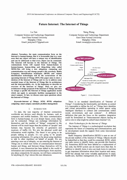
Future Internet: The Internet of ThingsLu Tan Computer Science and Technology DepartmentEast China Normal UniversityShanghai, ChinaEmail: jackytan217@ Abstract. Nowadays, the main communication form on theInternet is human-human. But it is foreseeable that in a nearsoon that any object will have a unique way of identificationand can be addressed so that every object can be connected.The Internet will become to the Internet of Things. Thecommunicate forms will expand from human-human tohuman-human, human-thing and thing-thing (also calledM2M).This will bring a new ubiquitous computing andcommunication era and change people's life extremely. RadioFrequency Identification techniques (RFID) and relatedidentification technologies will be the cornerstones of theupcoming Internet of Things (IOT).This paper aims to show askeleton of the Internet of Things and we try to address someessential issues of the Internet of Things like its architectureand the interoperability, etc. At the beginning we describe anoverview of the Internet of Things. Then we give ourarchitecture design proposal of the Internet of Things and thenwe design a specific the Internet of Things application modelwhich can apply to automatic facilities management in thesmart campus. At last, we discuss some open questions aboutthe Internet of Things.Keywords-Internet 0/ Things; M2M; RFID; ubiqutiouscomputing; smart campus; automatic/acilities management. I. INTRODUCTIONTo date, the vast majority of Internet connectionsworldwide are devices used directly by humans, such ascomputers and mobile handsets. The main communicationform is human-human. In a not distant future, every objectcan be connected. Things can exchange information bythemselves and the number of "things" connected to theinternet will be much larger than the number of "people" andhumans may become the minority of generators andreceivers of traffic [I). We mix the physical world andinformation world together. The future is not going to bepeople talking to people; it's not going to be peopleaccessing information. It's going to be about using machinesto talk to other machines on behalf of people. We areentering a new era of ubiquity, we are entering the Internet ofThings era in which new forms of communication betweenhuman and things, and between things themselves will berealized. A new dimension has been added to the world ofinformation and communication technologies: from anytime,any place connectivity for anyone, we will have connectivityfor anything [2]. Fig.l shows this new dimension. Neng WangComputer Science and Technology Department East China Normal University Shanghai, China Email: nwang@• O n the roo v e • O utdoo r s a i n door s • Nghl • O n t he roo v e 'Dayt i me • O utdoo r s • I n do o r s f r om the PC) • AI the PC Figure 1. A new dimensionThere is no standard identification of "Internet of Things". Considering the functionality and identity as central it is reasonable to define the loT as "Things have identities and virtual personalities operating in smart spaces using intelligent interfaces to connect and communicate within social, environment, and user contexts". A different definition that puts the focus on the seamless integration could be formulated as "Interconnected objects having an active role in what might be called Future Internet" [3). A. Main Technologiesfor the Internet of Things The Internet of Things is a technological revolution that represents the future of computing and communications, and its development needs the support from some innovational technologies. Radio frequency identification (RFID) is seen as one of the pivotal enablers of the Internet of Things. Objects should be indentified so that they could be connected. RFID, which use radio waves to identifY items, can provide this function [4]. Sometimes RFID has been labeled as a replacement of bar code, but RFIO system can do much more than that. In addition to identifY items it also can track items in real-time to get important information about their location and status. RFID has already had some valuable applications in retail,health-care, facilities management [5], etc. A mature RFIDtechnology provides a strong support for the Internet of Things.One of the biggest breakthroughs of the Internet of Things is making the physical world and information world together. Sensors play a very important role to bridge the gap between the physical world and information world. Sensors collect data from their environment, generating information raising awareness about context. So the change � of t �eir environment can be monitored and the correspondIng thIngs can make some responses if needed [6].Nanotechnology and miniaturization can make embedded intelligence in things themselves which called smart dev .i �es. They can process information, self-configure, make . deCls �on independently, just until then there will be a real thIng-thIng communication.B. Trends From a long perspective, the development trend of the Internet of Things includes three steps: embedded intelligence, connectivity, interaction.Firstly, we have embedded intelligences which can do actions automatically. There already have been many applications, for example: the RFID tag embedded in food can record the information about the food and we can get the information by using a RFID reader; the washing machine controller can make washing machine complete its work automatically; engine controllers and antilock b �ake controllers for automobiles; inertial guidance system, flIght control hardware/software and other integrated systems in aircraft and missiles; artificial arms with semi-functional hands, etc[7]. Though all of those devices are intelligent, we can see that they only work alone and locally, there's nothing to do with "network".So the next step is making every smart device can be connected. From the smart connected devices viewpoint, smart devices are not smart because they are just endowed with agent capabilities and all the actions are pre-designed by human, they are smart because they are connected. Things can be connected wired or wirelessly. In the Internet of Things wireless connection will to be the main way. Base on the existed infrastructure, there are many ways to connect a thing: RFID, ZigBee, WPAN, WSN, DSL, UMTS, GPRS, WiFi, WiMax, LAN, WAN, 3G, etc. Connect smart things makes interaction possible.Even though we can connect anything does not mean things can communicate by themselves. So new smart things should be created which can process information, selfconfigure, self-maintain, self-repair, make independent decision, eventually even play an active role in their own disposal. Things can interact, they exchange information by themselves. So the form of communication will change from human-human to human-thing to thing-thing. As the Internet of Things is application driven, new business applications should be created which can improve the innovation and development of the Internet of Things [8].Fig.2 shows a rough development trend of the Internet of Things [9]. TecIvloiogy Reach TECHNOLOGY ROADMAP THE INTERNET O F THINGS Miniilturiz::rti o o, power. effie ent electronics: ar.d Soti'.�71rA a!JAA l i; ::In!1 advar.:ed sensor fu s o n av a i 'a bIB speClrum r.eoper,tio, and t.,pr�"nC8: Abii� ro manitor and control ds�nl obI<ds .Ab�jlyof P hys ic a l-Wor l d inDoors to recerJe Webgeoloc3tioosi�nals L"",lillY �eupk 'lid Cost reduct olllcLldinaa Ubiquitous Positionin g to diffusion nto 200 Wi1ve of applicatil)'rS Surveilance, security, h l!"l!lK:;m!.II;Ul s l lI l�, 1oocJ,,1.'y, """m enl Ocrn3l"<l'orcxpc<li:ed t.Qistics V8rtica ..:\4ark91 Applicafions RFIDIag.,or IJCiilatingrouting, invcnl OfYing , and loss p'evenloo SJpply.Choin Hdpcrs21100 2010 Figure 2. Trend of the Internet of Things II. ARCHITECTURE 2020 TilJlH Current Internet has a five-layered architecture, running with TCP/IP protocols, which has worked well for a long time. However, in the Internet of Things billions of objects are connected which will create much larger traffic and need much more data storages. In addition to these, there still have some other challenges like security, governance, etc. But today's Internet was designed in the 1970s for purposes that bear little resemblance to today's usage scenarios and related traffic patterns. Mismatches between original design and current utilization are now beginning to hamper the Internet's potential. In the BLED Declaration [10] and other supporting statements, they all point out this point. So it is reasonable and essential to design a new architecture for the Internet of Things. . Redesign a new architecture is a very complex proJect, which needs consider many factors like reliability, scalability, modularity, interoperability, interface, QoS, etc. About the architecture design of the Internet of Things, service-oriented architecture (SOA), exploiting integration with Internet and interfacing with wide ranging edge technologies and associated networks is a key objective. For this objective, we should consider embracing a fully inclusive range of "edge" technologies, including RFIO for interfacing with the physical world; exploiting evolving object-connected data capture technologies and networking capabilities-sensory, location local communication and security; integration with the evo l ving Internet and some other technique issues. In addition to these, we should also view the needs for governance, QoS, security, privacy and other socioeconomic issues. Anthony Furness gives us a proposal about the .Internet of Things' architecture [11]. Fig.3, FigA are from thIS proposaland they show us the Internet of Things with different level of edge technologies.Pass i ve RFID datacarr i ers and UIDPhysicalin t erface zone I nterroga t or IGatewaydevice I nterroga t or IGatewaydevice A pp li cation commandsand r es pon s es Wider area communicationsand NetworksFigure 3. Internet of Things-at its most basic leveldata Sensory dataPhysicalinterface zoneFurther l aye r s of Data Capture TechnologyIHost Gate wayInformation Wide r area dev i ce communicationsand Networks Figure 4. Internet of Things-including RFID and other edgetechnologiesThen he gives the architecture of the Internet of Things he has designed. Fig.5Networksupported servicesEdge ·techno l ogy data capture and NetworksF i xed and mobile commun i c a t i on protocols Applications layer Middleware Access Gateway layerFigure 5. Architecture of the Internet of ThingsThis is a good proposal which has given us a rough solution of the Internet of Things' architecture. But there still are some further important issues we should think about carefully. The first is if every object is connected and things can exchange information by themselves, then the traffic and storages in the network will increase very rapidly with an exponential way. Does today's Internet really can bear this? Do we need a new backbone? Connecting every object andmake them can communicate independently is a very attractive vision, and yes we can imagine many cases in future that a thing needs to "talk" to another thing, but is it real necessary that an object "talks" to all the other objects? Why a toothbrush needs to "talk" to a fridge? In fact, the main connections of an object are with those objects which are in the same the Internet of Things application system as it. And it is could be seen that the Internet of Things is made up of many the Internet of Things application systems. From this point of view, we can have a new seeing of the Internet of Things. Fi .6 shows us this new view oint. Figure 6. Internet of ThingsThe Backbone Network may be today's Internet, may be not or may be its expansion.Now the Internet of Things' application situation is there already have been many applications like EPC Global, sma;t hospital and so on which seem work well. But the problem IS these application systems work alone, a�d even thou�h I mentioned before that today an object maInly commUnIcate with another object who is in the same application system, but there's no doubt that the technical future is connecting every application system and with the gro.wth of the I�te';1et of Things the communication between dIfferent apphcatlO� systems will become more and more frequently for theIr collaboration. But as the lack of global standards, they may have used different standards and technologies, so the interoperability is a problem. Only if we can solve the interoperability problem we can have a re�1 the Intern.et of Things. The authors come up with a solutIon that addIng a Coordination Layer into the Internet of Things' architecture design. The coordination layer responses to process the structure of packages from different application systems and reassemble them to an unified structure which can be identified and processed by every application system. Of course if the standards of the Internet of Things are completed then the systems which based on the standa!ds will have no problem in interoperability, this problem eXIsts between the existed application systems and the new deployed systems, and between the existed ap�lication systems themselves. Based on all above, we . gIve .our architecture design proposal of the Internet of ThIngs.Flg.7 shows our design.Application LayerMiddleware LayerCoordination LayerBackbone Network LayerExisted aloneAccess LayerApplicationSystemEdge TechnologyLayerFigure 7. The Internet of Things' ArchitectureIII. A THE INTERNET OF THINGS APPLICATION INCOLLEGEThe Internet of Things is not a theory, it's an application technology which our life can benefit fro�. I� fact, in a I�ngterm the value of the internet of things eXIsts In some speCIfic application. Specific application solutions will be one of themost important engines of the innovation and development of the Internet of Things. it's application driven. Currently, there already have some successful appli�ations in different fields like retail, food, logistics, transportatIOn, etc.So far we have mentioned so many stuffs about the Internet of Th i ngs, but what a real the Inte�et of Thin?s �pplication system like? Here the authors desIgn an apphcatIo� modelfor the college campus facilities management USIng the Internet of Things technology and take it as an example toshow what a real the Internet of Things like and how it can benefit our life.In the college campus, there are many buildings, e.g. teaching buildings, office buildings, library; dinnin� h�lIs, etc. Almost every building has its own heatIng, ventIlatIng, air condition systems (HV A C) and elevator system, those devices should be managed and maintained but it's not easy to make this job well done. Now we can use the Inte';1et �f Things technology in campus facilities manage�ent. Flg.S �s the architecture of this pilot project we have desIgned for thiS kind of facilities management.InformationWorldSolid lines --Data FlowDashed lines --Control FlowBuilding Facilities Control SystemCommunication ManagerWi-FiCommunication ManagerFigure 8. Architecture for Facilities Management We deploy enough number of RFID tags in the building which can monitor the HVAC and elevators' behavior, collect information, sense the change of their environment。
-1-Comparison between ADN (Aircraft DataNetwork) and Internet worldSui FAN Department of Electronics Engineer Beijing University of Posts and Telecommunications / Telecom ParisTECH Beijing, P. R. China 100876 Sui.fan @eurecom.frAbstractSince ARINC 664/AFDX standard has been selected for wide use in principal aircraft network in advanced airplanes. New generation Aircraft Network is currently under definition to enhance the AFDX in Aircraft Data Network with higher throughput and the support of more applications to open the door between Avionics Data Network and Internet world, which will introduce certain potential security issues. Therefore, this paper is going to introduce the difference between the two worlds.Keywords: AFDX, Internet world, OSI, Virtual Link, Security1 IntroductionFrom 1980th until recently, as the development of technique, ARINC 429,629,664 has been applied in different airplanes with different features. Especially now AFDX is popularly applied in advanced airplanes as local aircraft network communication protocol in Europe. Compared with Eureope, we are making progress recently but it’s still far than enough from catching up. The work is to study Avionics standards, including the basic AFDX tutorials and proposed security analysis draft by some AEEC working groups.Authors’ names are set in boldface, and each name is centered above the corresponding address. The lead author’s name is to be listed first (left-most), and the co-authors’ names (if different address) are set to follow. If only one co-author, list both author and co-author side by side.Please pay special attention to the instructions in section 3 regarding figures, tables, acknowledgements, and references.2 History of Avionics network standardsCurrently, the network architectures onboard avionics are important developments due mainly to increased complexity of embedded systems, in terms of growth of functions and therefore connections between these functions. These complexity problems have to be faced by taking advantage of technological developments based on the concept of architecture modular (which targets a greater share of resources for treatment and communication). Multi communications is one of the major challenges of new architectures generation. Various proposals about bus in avionics communication have been made, in particular under the ARINC which is the body architectures of civilian aircraft standards. Prior to AFDX, Aircraft Data Networks (ADN) utilized primarily the ARINC 429 standard. This standard, developed over thirty years ago and still widely used today, has proven to be highly reliable in safety critical applications. This ADN can be found on a variety of aircraft from both Boeing and-2-Airbus, including the Boeing 737, 747, 757, 767 and Airbus A330 and A340. ARINC 429 utilizes a unidirectional bus with a single transmitter and up to twenty receivers. A data word consists of 32 bits communicated over a twisted pair cable using the Bipolar Return-to-Zero Modulation. There are two speeds of transmission: high speed operates at 100 kbit/s and low speed operates at 12.5 kbit/s. ARINC 429 operates in such a way that its single transmitter communicates in a point-to-point connection, thus requiring a significant amount of wiring which amounts to added weight. Table 2-1:List of the avionics network historyTIME STANDARDs SPEEDSUPPORT FEATURE APPLIEDAIRPLANES1988 ARINC 429 12.5 ~ 100 kbit/s Unidirectional data bus standard; Single-transmitter multi-drop bus with up to 20 receivers B727,B737, B747,B757, B767, A310/A320, A330/A3401999 ARINC 629 2 Mbit/s8 Mbit/s Multi-transmitter protocolB777 2005 ARINC 664,AFDX100Mbits/s Based on ATM, Ethernet 802.3;Single-transmitter with receivers limited only by the number of ports on the switch A380, A400M, A350B787, 2008~ 2010 New Generataion study 1Gbit/s+On the study and research Advanced avion However, most of these proposals are based on media Communications which are old enough, as the ARINC 429 are reliable but with limited performance (100 kbit / s) who do not satisfy the requests from airline manufacturers today, even if they are of simplicity and reliability important.Another standard, ARINC 629, introduced by Boeing for the 777 provides increased data speeds of up to 2 Mbit/s and allowing a maximum of 120 data terminals. This improvement in avionics bus takes into account the constraints of determinism and real-time specific avionics applications directly at the level of techniques Time multiplexing proposed. This ADN operates without the use of a bus controller thereby increasing the reliability of the network architecture. The draw back of this system is that it requires hardware which can add significant cost to the aircraft. Because of this, other manufactures did not openly accept the ARINC 629 standard.The changing technology of local transmission of data (Ethernet switched, ATM, ...) has provided new answers to aircraft manufacturers and consider their use even if the nature of non-deterministic Users must be offset by strong assumptions, including trafficking the network. The solution adopted by Airbus for the new generation A380 is to reuse the basics of switched Ethernet. This technology allows a reuse of development tools and hardware components, which is to have a good confidence equipment reliability and ease of maintenance.ARINC 664 is defined as the next-generation aircraft data network (ADN). It is based upon IEEE 802.3 Ethernet and utilizes commercial off-the-shelf (COTS) hardware thereby reducing costs and development time.AFDX (Avionics Full Duplex switched Ethernet) is formally defined in Part 7 of the ARINC 664 specification. It has since been accepted by Boeing and is used on the Boeing 787 Dreamliner. AFDX bridges the gap on reliability of guaranteed bandwidth from the original ARINC 664 standard. It utilizes a star topology network of up to 24 end systems that are tied to a switch, where each switch can be bridged together to other switches on the network. By utilizing this form of network structure,-3-AFDX is able to significantly reduce wire runs thus reducing overall aircraft weight. Additionally, AFDX provides dual link redundancy and Quality of Service (QoS).However, switches prescribed by the standard ARINC664 conform to the IEEE 802.1D, is possible to lose frames. The problem comes from the level of switches, where different flows will compete for the use of the switch. Indeed, the confluences of traffic are potentially sources of non-determinism of latency through the network and can cause congestion of ports output switches. To address this problem of non-determinism in the AFDX network, several methods for analyzing temporal properties of communication media (latency, throughput, jitter, ...) were used.Besides, security exposure since it adopts the same Internet protocol nowadays while previously the security issues doesn’t exit because those old ADN standards are not compatible with the "Internet open world".3 Illustration of AFDX3.1 A FDX Pr otoco lThe new generations of aircraft boarded more avionics systems, increasing both safety and passenger comfort. These new functions result in a sharp increase in exchanges of data, which requires more flow and opportunities interconnection. The conventional buses communications avionics cannot answer this new demand, which has pushed manufacturers (Airbus and Boeing) to install a network board communication using switched Ethernet technology, also bring the era of AFDX.A vionics F ull D uple X Switched Ethernet (AFDX) is a standard that defines the electrical and protocol specifications (IEEE 802.3 and ARINC 664, Part 7) for the exchange of data between Avionics subsystems, to enable interconnection of system throughout the aircraft. It has three components :Avionics Subsystems, AFDX End System, AFDX Interconnect.Figure 3-1 AFDX Components in Avionics3.1.1 P ra ct ica l n et w o rk s t ru c tu r eOur proposed security mechanism should work for different kinds of environment, not only in A380, but to have an intuitive idea. Let’s have a look at the network structure embedded in current real Avionics first.Figure 3-2 Network structure embedded in AvionicsFigure 3-3 Practical AFDX Topology in A380 (Airbus)-4--5-In this real network structure, we could find all the transmitters or receivers (also called End System) connected with Switches, simply and almost symmetrical, using Star Topology. For every End System connected with Switch, there are two in case of redundancy (red and blue colour).The network consists of a hundred End System (123 End Systems), and 2x9 switches. These switches use FIFO policy.As a network-Full Duplex, of course each End System is linked to a single switch. Traffic on the Industrial AIRBUS is made up of 984 multicast streams, with between 1 and 15 recipients. Generally, hundreds of bytes in a frame can be more efficient than small bytes or large bytes.Note that in the structure, there are two Models called “SCI”, Security Control Interface, which are used to run some software filter function when connecting with Open World.3.2 C omp ar is o n Be tw ee n ADN an d I nt e rn et3.2.1 Mo de l C om p ar is on Be t w een ADN an d Int e rn e tDifference between AFDX and worldwide Internet in the Layer model lies mainly in the Data LinkLayer.Figure 3-4 AFDX under OSIFigure 3-5 End System Protocol Layers-6-As we see from the figures, AFDX transmitted UDP packets in transport layer. It has the application of TFTP as well as those services defined in ARINC 653.3.2.2 Co mm u n icat i on p roc es s of AFDXFigure 3-6.1 Transmission Figure 3-6.2 Receive3.2.3 Co mm u n i c at i on p or t s an d S A P po r t s i n AD N In previous ARINC 653, only communication ports are defined for Sampling or Queuing modes. It’s necessary to understand the conception of Queuing and Sampling in Avionics.•Sampling, when a new value of the data is received, it overwrites the old one. This mode is particularly appropriate for applications that need to receive data periodically. • Queuing mode, values are not erased; contrary, they are stored and presented in order of receipt,until the application had time to read them. This mode is most appropriate for aperiodic data transfers, for which it is necessary that all data being read.SAP (Service Access Point) Port, for TFTP service brought in AFDX, is used for TFTP transfers and communication with compliant networks.AFDX opens the door to a new avionics systemic approach and brings the introduction of Open world, that is why it makes sense in relation to the safety of flight.-7-Figure 3-7 The overall architecture of the information system onboard3.2.4 Di f fe re n ces i n Fr am es S t ru c tur e Now, based on those network structure figures, let’s have a look at more differences in frames structure and address as well as some protocols between the Ethernet protocol and AFDX.What’s different in AFDX frame structure:1. One particular byte to indicate AFDX sequence number;2. Only UDP packets in the payload because AFDX doesn’t use TCP currently.3. The Destination address in the frame only uses Multicast address.Figure 3-8 Structure of an AFDX Frame-8-Figure 3-9 Ethernet Frame Format (exemple)3.2.5 S e qu e n ce Nu m be rThe sequence number is introduced because of Redundancy Management (RM) that is used to protectcommunication, which is also used in the Integrity Check process.Figure 3-10 Network redundancy conceptFigure 3-10 shows the basic concept for network redundancy. A partition using transmitting End System prepares some data and passes it to the communications protocol stack. Here a sequence number field is added to each frame, and the sequence numbers are incremented on each successive frame, to enable the receive function to reconstruct a single ordered stream of frames without duplication before delivery to the receiving partition. In default mode each frame is sent across both of two networks. Upon reception, “First Valid wins” algorithm is used in the communications stack (below IP layer), which means that the first frame to be received from either network with the next valid sequence number is accepted and passed up the stack to the receiving partition. When the second frame is received with this sequence number, it is simply discarded. RM (Redundancy Management) is placed after IC (Integrity Checking).3.2.6 Di f fe re n ces i n MAC de st i na t ion Ad d re s singFigure 3-11 Addressing-9-Actually, in each End System, there would be several partitions. Each is responsible for different services. In each partition, there’s one source IP address and one destination IP address associated with each com port. That implies one partition could have multiple IP address corresponding with multiple ports. And each com port corresponds with one UDP port. Every Virtual Link corresponds with one MAC address.A MAC destination address in the AFDX frame should be a Group and Locally Administrated address and should be compliant with the following format. Like “03 00 00 00 00 0A”.Because there are not so many hosts used in aircraft, to simplify, only 16bits are used, the others areconstant.Figure 3-12 Mac destination addressA MAC source address is unicast address that is always like 02 00 00 10 00 55.Pay attention here, since redundancy management is used in AFDX, so the Interface_ID here is used toindicate network A (001) or network B (010).Figure 3-13 Mac Source address3.2.7 Di f fe re n ces i n IP a ddr es sA IP address is the same as Ipv4 except the Total Length field should range from 21 to 1499 bytes instead of from 21 to 1500 in IPv4 due to the Sequence Number.IP source address is used to identify the transmitting partition associated with the End System, like10.192.1.10.Figure 3-14 IP Source addressThe IP destination address in the IP header of the AFDX frame should be:• Either the IP Unicast address to identify the target subscriber like 10.192.1.10• Or an IP Multicast address compliant to the format shown in FigureFigure 3-15 IP destination address-10- 3.2.8 Co nc ep t ion of VLThe network AFDX establish, in accordance with the ARINC 664, a notion channels by the allocation of bandwidth. These channels are associated with a transmitter and are distributed by multicast (broadcast) Ethernet addresses. The switches enable segregation flows through access control lists(ACL) filtering, similarly to IP firewalls.Figure 3-16 Illustration of VL(Virtual Link) and BAG(bandwidth allocation gap)Each Virtual Link is decided by two parameters: BAG (bandwidth allocation gap) and Jitter. On a per VL basis the traffic regulator (traffic shaping function) should shape the flow to send no more than one frame in each interval of BAG millisecondsIn summary, a Virtual link is therefore characterized by:• Unidirectional,• A single source equipment,• A unique identifier (number and name of VL)• One or more addresses of destination,• A fixed path to reach these destinations on the network,• A maximum and minimum size of a frame (in bits, Smax and Smin)• The BAG is given by the formula: BAG = 1 ms x 2k , with k full 0 to 7, or 1 ms, 2 ms, 4 ms, 8 ms,16 ms, 32 ms, 64 ms, and 128 ms.We see that these data make it possible to define the maximum bandwidth link:it cannot issue the maximum size of a frame up all BAG. His maximum flow is in bits per second, noted ρ.Use of VLs allows the calculation of maximum deferred transmission which are needed to achieve the objectives of the system in aeronautics.The advantage of this concept is to control all flows entering the network. A bad behavior of a stream should not interfere with other flows, so we guarantee separated flows for avionics bus .The flow formed by a virtual link is assured of not being disturbed by other flows sharing the same physical links while during his route in the network.-11-On the other hand, the concept of a virtual link allows, through centralized management of the flow, that the amount of bandwidth allocated to the virtual links on a same Physical link. Indeed, each is VL logically isolated from others. These flows are logical connections between different network equipment where a source can also transmit flows to several destinations (Multicast). The VL is thusseen as a "pipe" on the network, as shown in Figure.Figure 3-17 VL as “”pipe”3.2.9 S w it ch Ta bleIn AFDX, it’s the Virtual identifier corresponding with in port and out port because each VL is unidirectional. In ordinary Internet world, the switch configuration tables always consists of the parameters of Mac address and forward ports, or as well as VLAN number (like Cisco switches); in AFDX network configuration of switch, besides the output ports, the input ports are also configured to map exact MAC destination address, which enforces the filter to ensure the right inbound frames and avoids ARP spoofing.Table 3-2 AFDX Switch table3.2.10 Di f fe re n t implement Mo de s in aircraft, controled by the PIN onboard.The most importance is that certain mode can’t return to the other mode in reverse. What’s more, the PIN who’s indicating the mode of aircraft also be indicated in binary by the certain bits in the MAC dest address.Figure 4-4 Aircraft Modes3.2.11 T h e d iff e ren c es du ri ng t h e c ommu n ic at ion As a summary, the difference of AFDX and Internet secures the avionics network to some extent, here comes to these features:1. Ethernet Full Duplex implies that the use of the algorithm CSMA / CD is no longer necessary.2. AFDX is statically defined; no default gateways.3. ARP, GMRP or Spanning tree are not necessary and should therefore be disabled.Because the configuration of the network must be static and fully known before taking off. This-12-implies The ARP tables in the hosts, the Switch tables (correspondence MAC address of destination/ port (s) of output) must be statically configured by the system integrator. 4.UDP requirements: Checksum is not used in AFDX 5.MUST send packet with TTL of 1 6.Connections are statically defined in AFDX. Therefore, keep alive packets are useless. 7.Only ICMP "echo request" and "echo reply" are allowed, which reduce certain risk of DoS attack using Dead-ping or ICMP tunneling. 8.Sequency number in frame for redundency management, in avoidance of certain repeated fragments transmission. 9. No TCP support service, which reduce certain risk of DoS attack using ACK or SYN Time outis not used for reassembly4 Future security considerationWhy we need to consider security for new generation aircraft network? Because, the aeronautic orgnization proposes targeted environment with three different points as following which implies the door between high seceured aircraft network and opne-minded Internet world has been open. 1.It has created an Internet Protocol network within the aircraft itself 2.The "Passenger Internet Service" has also connected to the "non-essential IP network" 3. The "non-essential IP network" is also connected to "Airline Ground Systems and Internet", whichimplies the aircraft will connect with world-wide InternetFigure 4-1 Proposed targeted Architecture by AEEC SECIn the future, we need to consider the safety and security issues of onboard networks in the new generation aircraft network and to standardize it between airlines and aircraft end systems suppliers. At present, there are several official documents proposed by some international organizations such as ARINC 664/P5 2005 which is about NETWORK DOMAIN CHARACTERISTICS AND INTERCONNECTION; such as A380 PKI Project (phase1 and phase 2 in 2005 that is about Digital Signature to protect software from malicious corruption between software supplier and Airframe / Aircraft Operator and the ARINC Report 811 in 2006 which took 18 months to study on “LANs in Aircraft: Safety, Security and Certification Issues, and Initial Acceptance Criteria”; such as ARINC 823 in 2007 which is about ACARS(Aircraft Communication Addressing and Report System) Data Link Message Security (Part 1) and Key Management (Part 2). On a plus side, the AEEC proposed numerous Technical Application Bulletin Security Use Cases 2008. Based on these reliable proposals, we have to take the security into consideration for our aircraft network communication, (i.e. impersonation on aircraft)especially when China wants to own independent development in the future.Ref e re nc es[1] AFDX Tutorial (May 2005), Condor Engineering, Inc[2] Hussein CHARARA, (2006) ÉVALUATION DES PERFORMANCES TEMPS REEL DE RESEAUXEMBARQUES AVIONIQUES[3] AEEC (October,2006) Working Together: Security Standards in the Aviation Industry[4].FAA (July 26, 2007) LANs in Aircraft including Safety and Security Issues and Initial AcceptanceCriteria[5] THALES GROUP, End System AFDX Functional Architecture-13-。
Evolved Packet Core1. IntroductionEvolved Packet Core (EPC) is a key component in modern mobile communication networks. It is responsible for providing advanced packet-based services to users while ensuring efficient network management and connectivity. In this article, we will delve into the intricacies of EPC, its architecture, functionalities, and its role in enabling next-generation mobile networks.2. EPC ArchitectureThe architecture of EPC comprises several key components that work together to deliver seamless connectivity and high-speed data transmission. These components include:2.1. Mobility Management Entity (MME)MME acts as the control plane entity in EPC and is responsible for managing the mobility aspects of user devices. It handles tasks such as authentication, location tracking, and handover management. MME ensures that users can move between different network cells seamlessly without any interruption in their service.2.2. Serving Gateway (S-GW)S-GW acts as an intermediate node between the radio access network and the core network. It is responsible for routing user data packets between the user device and the appropriate network elements. S-GW also performs tasks such as packet filtering, charging, and Quality ofService (QoS) enforcement.2.3. Packet Data Network Gateway (P-GW)P-GW serves as the interface between the EPC and external packet data networks such as the Internet or private networks. It handles tasks related to IP address allocation, authentication, and policy enforcement. P-GW also ensures secure and reliable data transmission between theusers and external networks.2.4. Policy and Charging Rules Function (PCRF)PCRF is responsible for enforcing policy and charging rules in EPC. It determines the appropriate QoS for each user and ensures that thenetwork resources are efficiently utilized. PCRF also plays a crucialrole in billing and charging, enabling service providers to offervarious data plans and billing options to their subscribers.3. Functionalities of EPCEPC provides a wide range of functionalities that enable advanced mobile services and seamless connectivity. Some of the key functionalities include:3.1. IP ConnectivityEPC ensures that users have seamless IP connectivity regardless of their location or the type of access network they are connected to. Itsupports both IPv4 and IPv6 addressing schemes, allowing for a smooth transition to the next-generation Internet protocol.3.2. Quality of Service (QoS) ManagementEPC enables service providers to deliver different levels of QoS tousers based on their specific requirements. It ensures that critical applications such as video streaming or VoIP receive higher priority, resulting in an improved user experience.3.3. Mobility ManagementEPC enables users to move between different network cells or access technologies without any interruption in their service. It ensures smooth handovers and seamless connectivity, enabling users to stay connected while on the move.3.4. Security and PrivacyEPC employs various security measures to protect user data and ensure privacy. It includes authentication mechanisms, encryption, and secure tunnels to prevent unauthorized access and data breaches.4. Benefits of EPCImplementing EPC in mobile networks offers several benefits to both service providers and end-users. Some of the notable benefits include:4.1. Enhanced User ExperienceEPC enables faster data transmission and lower latency, resulting in a superior user experience. It allows users to enjoy high-quality video streaming, seamless voice calls, and efficient browsing, even in high-traffic areas.4.2. Scalability and FlexibilityEPC architecture is designed to handle the growing demand for data-intensive services. It offers scalability and flexibility, allowing service providers to efficiently manage network resources and accommodate the increasing number of connected devices.4.3. Cost EfficiencyBy optimizing resource utilization and streamlining network management, EPC helps service providers reduce operational costs. It enables efficient traffic management, reduces equipment requirements, and simplifies network maintenance, resulting in significant cost savings.ConclusionEvolved Packet Core is an essential component in modern mobile networks. It provides advanced packet-based services, ensures seamless connectivity, and offers a range of functionalities that enhance the user experience. With its scalable architecture and cost-efficient operation, EPC serves as a foundation for next-generation mobile communication networks. By adopting EPC, service providers can deliver high-speed data services, meet the growing demands of users, and drive innovation in the telecommunications industry.。

PRODUCT DATA SPA921IP PhoneModel No.Advanced, Affordable, Feature Rich IP Phone for the Home Office and Business Comprehensive Interoperability and SIP Based Feature Set Based on the SIP standard, the SPA921 has been tested to ensure comprehensive interoperability with equipment from VoIP infrastructure leaders enabling service providers to quickly roll-out competitive, feature rich services to their customers. With hundreds of features and configurable sevice parameters, the SPA921addresses the requirements oftraditional business users whileleveraging the advantages of IPtelephony. Features such aseasy station moves, presence,and shared line appearances(across local and geographicallydispersed locations) are justsome of the many advantages ofthe SPA921.Carrier-Grade Security,Provisioning, andManagementThe SPA921 uses standardencryption protocols toprovide secure remoteprovisioning and unobtrusivein-service software upgrades.Linksys secure remoteprovisioning tools includedetailed performancemeasurement andtroubleshooting features,enabling network providers todeliver high quality support totheir subscribers. Remoteprovisioning also saves serviceproviders the hassle andexpense of managing, pre-loading, and re-configuringcustomer premise equipment(CPE).•One Voice Line with Two Call Appearances•Backlit Pixel Based Display: 128x64 Monochrome Graphical Liquid Crystal Display (LCD)•Line Status - Active Line Indication, Name and Number•Menu Driven User Interface•Shared Line Appearance **•SpeakerphoneFeatures•Call Hold•Music on Hold **•Call Waiting•Caller ID Name and Number and Outbound Caller ID Blocking•Outbound Caller ID Blocking•Call Transfer - Attended and Blind•Three Way Call Conferencing with Local Mixing•Connects to External Conference Bridge for Multi-party Conferencing•Automatic Redial of Last Calling and Last Called Numbers•On-Hook Dialing•Call Pick Up - Selective and Group **•Call Park and UnPark **•Call Swap•Call Back on Busy•Call Blocking - Anonymous and Selective•Call Forwarding - Unconditional, No Answer, On Busy•Hot Line and Warm Line Automatic Calling•Call Logs (60 entries each): Made, Answered, and Missed Calls•Redial from Call Logs•Personal Directory with Auto-dial (100 entries)•Do Not Disturb (callers hear line busy tone)•Digits Dialed with Number Auto-Completion•Anonymous Caller Blocking•URI (IP) Dialing Support (Vanity Numbers)•On Hook Default Audio Configuration (Speakerphone and Headset)•Multiple Ring Tones with Selectable Ring Tone per Line•Called Number with Directory Name Matching•Call Number using Name - Directory Matching or via Caller ID•Subsequent Incoming Calls with Calling Name and Number•Date and Time with Intelligent Daylight Savings Support•Call Duration and Start Time Stored in Call Logs•Call Timer•Name and Identity (Text) Displayed at Start Up•Distinctive Ringing Based on Calling and Called Number•Ten User Downloadable Ring Tones - Ring Tone Generator Free from •Speed Dialing, Eight Entries•Configurable Dial/Numbering Plan Support•I ntercom**•Group Paging **•NAT Traversal, including STUN Support•DNS SRV and Multiple A Records for Proxy Lookup and Proxy Redundancy•Syslog, Debug, Report Generation, and Event Logging•Secure Call Encrypted Voice Communication Support•Built-in Web Server for Administration and Configuration with Multiple Security Levels•Automated Remote Provisioning, Multiple Methods. Up to 256 Bit Encryption: (HTTP, HTTPS, TFTP)•Optionally Require Admin Password to Reset Unit to Factory Defaults•** Feature requires support by call server•Pixel Based Display: 128x64 Monochrome LCD Graphical Display •Dedicated Illuminated Buttons for:• Audio Mute On/Off • Headset On/Off • Speakerphone On/Off •Four Soft Key Buttons •Four Way Rocking Directional Knob for Menu Navigation •Voice Mail Message Waiting Indicator Light •Voice Mail Message Retrieval Button •Dedicated Hold Button •Settings Button for Access to Feature, Set-up, and Configuration Menus •Volume Control Rocking Up/Down Knob Controls Handset, Headset, Speaker, Ringer •Standard 12-Button Dialing Pad •High Quality Handset and Cradle •Built-In High Quality Microphone and Speaker •Headset Jack – 2.5 millimeter •Ethernet LAN – 10BaseT RJ-45• 5 volt DC Universal (100-240 Volt) Switching Power Adaptor •LED Test Function •FCC (Part 15, Class B) , CE Mark, A-Tick •Password Protected System, Preset to Factory Default •Password Protected Access to Administrator and User Level Features •HTTPS with Factory Installed Client Certificate •HTTP Digest - Encrypted Authentication via MD5 (RFC 1321)•Up to 256-bit AES Encryption •Quick-Start Installation and Configuration Guide •User Guide •Administration Guide •Provisioning Guide - For Service Providers Only • 1 - SPA921 IP Phone, Handset, and Stand • 1 - Handset Cord - 56 cm (26 in)• 1 - 5v Power Adapter - 1.8 m (6 ft) Cord • 1 - RJ45 Ethernet Cable - 1.8 m (6 ft) Cord • 1 - Quick Installation Guide Environmental Dimensions Unit Weight Operating Temp.Storage Temp.Operating Humidity Storage Humidity 7.68 x 6.30. x 7.09 in (195 x 160 x 180 mm) W x H x D2.15 lbs ( 0.9752 kg)41º~113ºF (5º~45ºC)-13º~185ºF (-25º~85ºC)10~90% Non-condensing10~90% Non-CondensingPackage ContentsSecurityRegulatoryCompliance DocumentationFeaturesSpecifications ModelData NetworkingVoice GatewayProvisioning,Administration &Maintenance:Power SupplyPhysical Interfaces:Indicator Lights/LED:SPA921Note: Many features are programmable within a defined range or list of options. Pleasesee the SPA Administration Guide for details. The target configuration profile is up-loaded to the SPA922 at the time of provisioning.MAC Address (IEEE 802.3)IPv4 - Internet Protocol v4 (RFC 791) upgradeable to v6 (RFC 1883)ARP - Address Resolution ProtocolDNS - A Record (RFC 1706), SRV Record (RFC 2782)DHCP Client - Dynamic Host Configuration Protocol (RFC 2131)ICMP - Internet Control Message Protocol (RFC792)TCP - Transmission Control Protocol (RFC793)UDP - User Datagram Protocol (RFC768)RTP - Real Time Protocol (RFC 1889) (RFC 1890)RTCP - Real Time Control Protocol (RFC 1889)DiffServ (RFC 2475), Type of Service - TOS (RFC 791/1349)VLAN Tagging 802.1p/q - Layer 2 QoSSNTP - Simple Network Time Protocol (RFC 2030)SIPv2 - Session Initiation Protocol Version 2 (RFC 3261, 3262, 3263, 3264)SIP Proxy Redundancy - Dynamic via DNS SRV, A RecordsRe-registration with Primary SIP Proxy ServerSIP Support in Network Address Translation Networks - NAT (including STUN)SIPFrag (RFC 3420)Secure (Encrypted) Calling via Pre-Standard Implementation of Secure RTPCodec Name AssignmentVoice Algorithms:- G.711 (A-law and µ-law)- G.726 (16/24/32/40 kbps)- G.729 A- G.723.1 (6.3 kbps, 5.3 kbps)Dynamic Payload SupportAdjustable Audio Frames Per PacketDTMF: In-band and Out-of-Band (RFC 2833) (SIP INFO)Flexible Dial Plan Support with Inter-Digit TimersIP Address / URI Dialing SupportCall Progress Tone GenerationJitter Buffer - AdaptiveFrame Loss ConcealmentVAD - Voice Activity Detection with Silence SuppressionAttenuation / Gain AdjustmentsMWI - Message Waiting Indicator TonesVMWI - Voice Mail Waiting Indicator - Via NOTIFY, SUBSCRIBECaller ID Support (Name and Number)Third Party Call Control (RFC 3725)Integrated Web Server Provides Web Based Administration and ConfigurationTelephone Key Pad Configuration via Display Menu / NavigationAutomated Provisioning and Upgrade via HTTPS, HTTP, TFTPAsynchronous Notification of Upgrade Availability via NOTIFYNon-intrusive, In-Service UpgradesReport Generation and Event LoggingStatistics Transmitted in BYE MessageSyslog and Debug Server Records - Configurable Per Line1 10baseT RJ-45 Ethernet Port (IEEE 802.3)Handset: RJ-7 ConnectorBuilt-in Speakerphone and MicrophoneHeadset 2.5 mm PortSwitching Type (100-240v) AutomaticDC Input Voltage: +5 Volts DC at 2.0 Amps MaximumPower Consumption: 5 WattsPower Adapter: 100-240v - 50-60Hz (26-34VA) AC Input, 1.8m (6 ft) cordFour (4) Call Appearance/Line Buttons with Associated Tricolor LEDLine LED State Indication: Active, Idle, On Hold, UnregisteredSpeakerphone On/Off Button with LEDHeadset On/Off Button with LEDMute Button with LEDMessage Waiting Indicator LEDVoicemail Message Retrieval ButtonHold ButtonLED Test FunctionStylish and functional in design, the SPA921 IP Phone is ideal for a residence or business using a hosted IP telephony service, an IP PBX, or a large scale IPCentrex deployment. The SPA921 leverages industry leading VoIP technology from Linksys to deliver an upgradeable high quality IP phone that is unparalleled in features, value, and support.Standard features on the SPA921 include a high resolution graphical display, speakerphone, and a 2.5 mm head-set port. The SPA921 supports one line with two call appearances and provides support for three way conferencing,attended call transfer, and placing a call on hold to answer an incoming call. The line can be configured as a unique phone number (or extension), or can be configured to share a number that is assigned to multiple phones. •Full featured one-line business class IP phone•Connect directly to an Internet Telephone Service Provider or connect to an IP PBX•Speakerphone. Caller ID. Call Hold, Transfer, Conferencing, and more•Easy installation with secure remote provisioning. Menu based and web based configuration.Linksys A Division of Cisco Systems, Inc.18582 Teller Avenue Irvine, CA 92612 USA E-mail:************************************Web: Linksys products are available in more than 50 countries, supported by 12 Linksys Regional Offices throughout the world. For a complete list of local Linksys Sales and Technical Support contacts, visit our Worldwide Web Site at .Specifications are subject to change without notice. Linksys is a registered trademark or trademark of Cisco Systems, Inc. and/or its affiliates in the U.S. and certain other countries. Copyright © 2006 Cisco Systems, Inc. All rights reserved. Other brands and product names are trademarks or registered trademarks oftheir respective holders.SPA921-SP-DS- 60130NC BW 11111212Linksys Phone Adapter Comparison Chart。
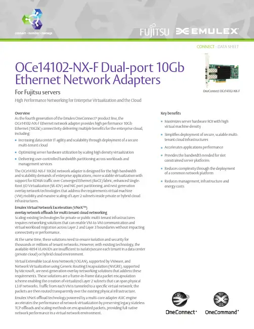
Key benefitsnMaximizes server hardware ROI with highvirtual machine densitynSimplifies deployment of secure, scalable multi-tenant cloud infrastructuresnAccelerates applications performance nProvides the bandwidth needed for slot constrained server platformsnReduces complexity through the deployment of a common network platformnReduces management, infrastructure and energy costsOverviewAs the fourth generation of the Emulex OneConnect® product line, theOCe14102-NX-F Ethernet network adapter provides high performance 10GbEthernet (10GbE) connectivity delivering multiple benefits for the enterprise cloud, including:nIncreasing data center IT agility and scalability through deployment of a secure multi-tenant cloudn Optimizing server hardware utilization by scaling high density virtualization nDelivering user-controlled bandwidth partitioning across workloads and management servicesThe OCe14102-NX-F 10GbE network adapter is designed for the high bandwidth and scalability demands of enterprise applications, more scalable virtualization with support for RDMA traffic over Converged Ethernet (RoCE) fabric, enhanced Single-Root I/O Virtualization (SR-IOV) and NIC port partitioning, and next generation overlay network technologies that address the requirements virtual machine(VM) mobility and massive scaling of Layer 2 subnets inside private or hybrid cloud infrastructures.Emulex Virtual Network Exceleration (VNeX™)overlay network offloads for multi-tenant cloud networkingScaling existing technologies for private or public multi-tenant infrastructures requires networking solutions that can enable VM-to-VM communication andvirtual workload migration across Layer 2 and Layer 3 boundaries without impacting connectivity or performance.At the same time, these solutions need to ensure isolation and security forthousands or millions of tenant networks. However, with existing technology, the available 4094 VLAN IDs are insufficient to isolate/secure each tenant in a data center (private cloud) or hybrid cloud environment.Virtual Extensible Local Area Network (VXLAN), supported by VMware, andNetwork Virtualization using Generic Routing Encapsulation (NVGRE), supported by Microsoft, are next-generation overlay networking solutions that address these requirements. These solutions are a frame-in-frame data packet encapsulation scheme enabling the creation of virtualized Layer 2 subnets that can span physical L3 IP networks. Traffic from each VM is tunneled to a specific virtual network; the packets are then routed transparently over the existing physical infrastructure.Emulex VNeX offload technology powered by a multi-core adapter ASIC engineaccelerates the performance of network virtualization by preserving legacy stateless TCP offloads and scaling methods on encapsulated packets, providing full native network performance in a virtual network environment.High Performance Networking for Enterprise Virtualization and the CloudOCe 14102-NX-F Dual-port 10Gb Ethernet Network AdaptersOneConnect OCe14102-NX-FCONNECT - DATA SHEETFor Fujitsu serversEthernet Network AdaptersRDMA supportThe OCe14102-NX-F adapters leverage RoCE enabling server to server data movement directly between application memory without any CPU involvement providing high throughput and data acceleration on a standard Ethernet fabric without the need for any specialized infrastructure or management.Optimized host virtualization density with SR-IOV supportSR-IOV optimizes I/O for VMs, enabling higher host server virtualization ratios to deliver maximum server ROI. SR-IOV provides a more cost-effective solution than multiple, physical adapter ports. SR-IOV enables multiple VMs to directly access the OCe14102-NX-F’s I/O resources, thus allowing VM networking I/O to bypass the host and take a path directly between the VM and the adapter, eliminating redundantI/O processing in the hypervisor. This, in turn, allows higher I/O performance, lower CPU utilization and significantly reduced latency as compared to the alternative of software-emulated NIC devices that are implemented in the hypervisor. Optimized bandwidth allocation with EmulexUniversal Multi-Channel port partitioningEmulex Universal Multi-Channel (UMC) is ideal for virtualized server environments because bandwidth allocation can be optimized to support virtual machine migration, management and I/O intensive applications. UMC allows multiple PCI physical functions to be created on each adapter port. Each port on the OCe14102-NX-F can be configured with up to sixteen functions.Simplified management with Emulex OneCommand® Manager applicationThe Emulex OneCommand Manager application provides centralized management of Emulex OneConnect CNAs and LightPulse® HBAs throughout the data center from a single management console. The OneCommand Manager application providesa graphical user interface (GUI) and a scriptable command line user interface (CLI). Emulex OneCommand Manager for VMware is fully integrated with VMware vCenter to simplify management for virtual server deployments.Fourth generation platform delivers enterprise-class reliability and performance Leveraging generations of advanced, field-proven controller and adapter technology, OCe14102-NX-F adapters meet the robust interoperability and reliability requirements of enterprise and scale-out data centers.Key featuresn Superior network scalability—10GbE bandwidth on common software platformn SR-IOVn Data acceleration with RoCE supportn Powerful hardware offload for:- Overlay networks (NVGRE and VXLAN)- Stateless TCPn Greater bandwidth with PCIe 3.0n VMware vSphere NetQueue supportn Microsoft Windows Server VMQ andDynamic VMQ supportEthernet Network AdaptersController· Skyhawk(Emulex Engine, XE100 series controllers) Ethernet standards· Single IEEE 802.3ba 40GBASE Ethernet port (40GBASE-SR4/40GBASE-CR4)· Single or Dual IEEE 802.3-2008 10GBASE Ethernet ports (10GBASE-SR/10GBASE-LR/10GBASE-CR)· Single or dual 1GBaseX/SGMII auto negotiation · IEEE 802.1Q virtual LANs (VLAN)· IEEE 802.3x Flow control with Pause frames· IEEE 802.1Qbg Edge Virtual Bridging· IEEE 802.1Qaz Enhanced Transmission Selection (ETS); Data Center Bridging Capability Exchange (DCBX)· IEEE 802.1Qbb Priority Flow Control (PFC)· IEEE 802.3ad Link Aggregation/LACP· IEEE 802.1AB Link Layer Discovery Protocol (LLDP) Ethernet network interface (Layer 2 NIC) and TCP/IP · NDIS 6.0, 6.2, 6.3-compliant Ethernet functionality · IPv4/IPv6 TCP, UDP checksum offload· IPv4/IPv6 Receive Side Scaling (RSS)· IPv4/IPv6 Large Receive Offload (LRO)· IPv4/IPv6 Large Send Offload (LSO)· Dynamic VMQ (Windows Server 2012 Hyper-V) and NetQueue (VMware vSphere)· Programmable MAC and VLAN addresses· 128 MAC/VLAN addresses per port· Support for hash-based Multicast MAC address filters· Support for hash-based Broadcast frame filters per port· VLAN offloads (insertion and extraction)· Jumbo frame support up to 9000 Bytes I/O virtualization· Stateless L2, L3, and L4 offloads for frame-in-frameencapsulation (VXLAN, NVGRE)· PCI-SIG Address Translation Service (ATS) v1.0· Support for up to 512 hardware queues· Virtual Switch Port Mirroring for diagnosticpurposes· Virtual Ethernet Bridging (VEB)· Virtual Ethernet Port Aggregator (VEPA)· OneConnect Universal Multi-Channel™ (UMC),support for up to 16 PCIe physical functions (PFs)per adapter which can be used as partitions asfollows:- OCe14401 Ethernet adapter, the port cansupport 16 NIC functions- OCe14101 or OCe14102 Ethernet adapters,each port can support eight NIC functions- Note: the system hardware must support andenable ARI and the host operating system mustsupport ARI for maximum number of functionsto be enabled; see Emulex UMC manual formore details· NIC Single Root I/O Virtualization (SR-IOV)- up to 63 virtual functions (VFs) per port· QoS for controlling and monitoring bandwidthassigned to and used by virtual entities· Configurable control of network bandwidth byphysical port, queue, or protocol· Traffic shaping and QoS across each VF and PFConverged Enhanced Ethernet (CEE)and Datacenter Bridging (DCB)· IEEE 802.1Qbb Priority Flow Control (PFC)· IEEE 802.1Qaz Enhanced Transmission Selection(ETS)· IEEE 802.1Qaz Data Center Bridging Exchange(DCBX)· Absolute per-priority rate control option/configurationRemote Direct Memory Access (RDMA)· Direct data placement in application bufferswithout CPU intervention· Supports IBTA RoCE specifications· Linux Open Fabrics Enterprise Distribution (OFED)support· Low latency queues for small packet sends andreceives· Windows Server SMB Direct (SMB over RDMA)PCI Express (PCIe) interface· PCIe 3.0 x8 (8, 5.0, and 2.5 GT/s per lane)compliant interface:- Up to 64 Gb/s full duplex bandwidth- Configurable width and speed to optimizepower versus bandwidth· Support for up to 16 PCIe physical functions (PFs)· Support for x1, x2, x4, and x8 links widths· NIC Single Root I/O Virtualization (SR-IOV)- up to 63 virtual functions (VFs) per port· Message Signal Interrupts (MSI-X)· Advanced Error Reporting (AER)· Completion Timeout (CTO)· Function Level Reset (FLR)· Alternative Routing ID Interpretation (ARI)Comprehensive OS support· Windows· Red Hat Enterprise Linux· SUSE® Linux Enterprise Server· Oracle Linux· VMware vSphere· CentOS· Debian· Ubuntu· FreeBSD· CITRIX XENServerManagement, boot support· vCenter management plugin support· Role-based management, integrated with ActiveDirectory and LDAP· Multi-channel configuration and bandwidthcontrol· UEFI and x86 remote boot support includingPXE v2.1, UEFI 2.3.1· MAC statistics gathering(SNMP, Ethernet MIB, MIB2, RMON, RMON2)· Offline and online firmware updates· Integrated thermal sensor works withmanagement utilitiesHardware environments· Fujitsu x86, x64 serversPlease refer to the product page on for further details.Ethernet Network AdaptersInterconnectCopper· SFP+ Direct Attached Twin-Ax Copper interface · Standards compliant passive copper cables up to 5m and active copper cables up to 10m Optical· Optic 10GBASE-SR short wave lasers with LC type connector supported up to 300m on laser-optimized OM3 multimode fiber (MMF) cables · Optic 10GBASE-LR long wave lasers with LC type connector supported up to 10Km single mode fiber (SMF) cable, Ethernet use onlyPhysical dimensions· Short, low profile MD2 form factor card · 167.64mm x 68.91mm (6.60” x 2.71”)· Standard, full height bracket installed (low-profile bracket available)Environmental requirements· Operating temperature: 0° to 55°C (32° to 131°F)· Storage temperature: -40° to 70°C (-40° to 158°F)· Relative humidity: 5% to 95% non-condensingAgency and product safety approvalsNorth America· FCC/Industry Canada Class A · UL/CSA Recognized· Class 1 Laser Product per DHHS 21CFR (J)Europe · CE Mark· EU RoHS compliant · TUV Bauart Certified· Class 1 Laser Product per EN60825-1Australia · C-Tick Mark Japan· VCCI Class A Taiwan· BSMI Class AKorea· MSIP (formally KCC/MIC) Class A China· China RoHS CompliantOrdering informationPlease refer to Fujitsu website for product ordering: /dl.aspx?id=eba2c160-53e0-4aac -b526-149f84f12bfdELX15-2456 · 2/15World Headquarters 3333 Susan Street, Costa Mesa, CA 92626 +1 714 662 5600Bangalore, India +91 80 40156789 | Beijing, China +86 10 84400221Dublin, Ireland +35 3 (0) 1 652 1700 | Munich, Germany +49 (0) 89 97007 177Paris, France +33 (0) 158 580 022 | Tokyo, Japan +81 3 5325 3261 | Singapore +65 6866 3768Wokingham, United Kingdom +44 (0) 118 977 2929 | Brazil +55 11 3443 7735©2015 Emulex, Inc. All rights reserved.This document refers to various companies and products by their trade names. In most cases, their respective companies claim these designations as trademarks or registered trademarks. This information is provided for reference only. Although this information is believed to be accurate and reliable at the time of publication, Emulex assumes no responsibility for errors or omissions. Emulex reserves the right to make changes or corrections without notice. This document is the property of Emulex and may not be duplicatedwithout permission from the Company.。
2021年10月 Journal on Communications October 2021 第42卷第10期 通 信 学 报 Vol.42 No.10加密去重场景下基于AONT和NTRU的密钥更新方案 贾春福1,2,哈冠雄1,2,武少强1,2,陈杭1,2,李瑞琪1,2 (1. 南开大学网络空间安全学院,天津 300350;2. 天津市网络与数据安全技术重点实验室,天津 300350)
摘 要:密钥更新是对抗密钥泄露的有效方法。现有加密去重系统大多基于消息锁加密实现,拥有相同数据的多个用户共享同一加密密钥,某一用户更新密钥时其他数据所有者需同步该更新,这将引起较大的计算和通信开销。针对这一问题,提出了一种基于AONT和NTRU的密钥更新方案,设计了一个AONT的变体以解决多用户密钥更新时的同步问题,引入了一种基于NTRU的代理重加密方案以降低密钥更新过程中的系统通信开销和客户端计算开销。效率分析与实验结果表明,所提方案与现有方案相比具有更高的加解密效率,显著降低了密钥更新过程中的时间开销。 关键词:云存储;加密去重;密钥更新;AONT;NTRU 中图分类号:TP309.2 文献标识码:A DOI: 10.11959/j.issn.1000−436x.2021187
AONT-and-NTRU-based rekeying scheme for encrypted deduplication
JIA Chunfu1,2, HA Guanxiong1,2, WU Shaoqiang1,2, CHEN Hang1,2, LI Ruiqi 1,2 1. College of Cyber Science, Nankai University, Tianjin 300350, China 2. Tianjin Key Laboratory of Network and Data Security Technology, Tianjin 300350, China
ConnectX ®InfiniBand Smart Adapter Cards for OCPHigh Performance Smart Adapter Cards supporting up to 200Gb/s InfiniBand &Ethernet in Open Compute Project Spec 2.0 & 3.0 Form Factors†† For illustration only. Actual products may vary.InfiniBand/VPI OCP††Mellanox® Virtual Protocol Interconnect® (VPI) smart adapter cards in OCP 2.0 & 3.0 form factors combine high-performance leading features with best-in-class efficiency, enabling the highest data center performance.World-Class Performance and ScaleMellanox smart adapter cards deliver industry-leading connectivity for performance-driven server and storage applications. ConnectX adapter cards offer high bandwidth coupled with ultra-low latency and in-network computing to enable faster access and real-time responses. Mellanox offers a variety of OCP Spec 2.0 and OCP Spec 3.0 compliant adapter cards, providing best-in-class performance and efficient computing through advanced acceleration and offload capabilities. These advanced capabilities free up valuable CPU cores for other tasks, while increasing data center performance, scalability and efficiency, include:• IBTA Remote Data Memory Access (RDMA)• NVMe-over-Fabrics (NVMe-oF) offloads• In-network computing and MPI operation accelerations• Single Root IO Virtualization (SR-IOV)• GPUDirect® communication acceleration• Mellanox Multi-Host®for connecting multiple compute or storage hosts to a single interconnect adapter card• Enhanced security solutions Complete End-to-End InfiniBand Networking ConnectX OCP smart adapter cards are part of Mellanox’s InfiniBand end-to-end portfolio for data centers which also includes switches, application acceleration packages, and cabling to deliver the best price-performance value proposition for network and storage solutions. With Mellanox, IT managers can be assured of the highest performance, reliability, most efficient network fabric at the lowest cost, and the best return on investment.In addition, Mellanox Unified Fabric Manager (UFM®) management software greatly simplifies network provisioning, monitoring and diagnostics, providing the agility and efficiency for scalability and future growth. Featuring an intuitive graphical user interface, UFM provides in-depth visibility and control.Open Compute ProjectThe OCP NIC 3.0 specification extends the capabilities of OCP NIC 2.0 design specification. OCP 3.0 defines a different form factor and connector style than OCP 2.0. The OCP 3.0 specification defines two basic card sizes: Small Form Factor (SFF) and Large Form Factor (LFF). Mellanox OCP NICs are currently supported in a SFF.** Future designs may utilize LFF to allow for additional PCIe lanes and/or network ports,InfiniBand OCP Smart Adapter CardsSpecs, Feature Support & Ordering Part Numbers--Notes:1. Additional information is available in product briefs.2. This brochure describes hardware features and capabilities. Please refer to the driver and firmware release notes on for feature availability.3. OPN2.0 Product Notes:• Shipped without a bracket.• For more details, please refer to the Open Compute Project 2.0 Specifications.4. OCP3.0 Product Notes:• The last digit of OPN-suffix displays the default bracket option: I = Internal Lock; E = Ejector Latch. For other bracket types, contact Mellanox.• Dimensions without brackets are 167.65mm x 68.90mm. All tall-bracket adapters are shipped with the tall bracket mounted and a short bracket as an accessory.Enabling High Performance Computing (HPC) and Artificial Intelligence (AI) ApplicationsMellanox InfiniBand/VPI adapters are the perfect solution for the evolving data-centric paradigm. Technologies within this model include the innovative In-Network Computing offloads that transform the data center interconnect into a “distributed CPU,” and “distributed memory,” overcoming performance bottlenecks and enabling faster and more scalable data analysis. Mellanox’s advanced In-Network Computing accelerations and RDMA offload capabilities optimize the performance of a wide variety of HPC and machine learning systems in bioscience, media, automotive design, CFD and manufacturing, weather research, oil and gas, and other markets.As a core In-Networking Computing technology, Mellanox Scalable Hierarchical Aggregation and Reduction Protocol (SHARP)™ optimizes MPI operations and GPU communications performance, decreasing the data load on the network and dramatically reducing operation times, while freeing up CPU and/or GPU resources for other tasks.Virtual Protocol Interconnect® (VPI)Mellanox’s VPI technology enables any standard networking, clustering, storage, and management protocol to seamlessly operate over any converged network leveraging a consolidated software stack. Each port can operate on InfiniBand or Ethernet fabrics, and supports IP over InfiniBand (IPoIB) and RDMA over Converged Ethernet (RoCE). VPI simplifies I/O system design and makes it easier for IT managers to deploy infrastructure that meets the challenges of a dynamic data center.I/O VirtualizationMellanox adapter cards provide comprehensive support for virtualized data centers with Single-Root I/O Virtualization (SR-IOV) allowing dedicated adapter resources and guaranteed isolation and protection for virtual machines (VM) within the server. I/O virtualization on InfiniBand gives data center managers better server utilization and LAN and SAN unification while reducing cost, power, and cable complexity.Mellanox Multi-Host SolutionMellanox Multi-Host® technology provides high flexibility and major savings in building next generation, scalable, high-performance data centers. Mellanox Multi-Host connects multiple compute or storage hosts into a single interconnect adapter, separating the adapter’s PCIe interface into multiple and independent PCIe interfaces with no performance degradation. The technology enables designing and building new scale-out heterogeneous compute and storage racks with direct connectivity between compute elements, storage elements and the network, better power and performance management, while achieving maximum data processing and data transfer at minimum capital and operational expenses. Accelerated StorageA consolidated compute and storage network provides significant cost-performance advantages over multi-fabric networks. Standard block and file access protocols leveraging InfiniBand RDMA result in high-performance storage access. Mellanox adapter cards support NVMe over Fabrics as well as other technologies including SRP, iSER, NFS RDMA, SMB Direct, SCSI and iSCSI. ConnectX adapters also offer a flexible Signature Handover mechanism based on the advanced T-10/DIF implementation.ConnectX®-6 Adapter CardConnectX-6 is the world’s first 200Gb/s HDR InfiniBand and Ethernet network adapter card, offering world-leading performance, smart offloads and In-Network Computing. ConnectX-6 with VPI provides two ports of 200Gb/s supporting HDR, HDR100, EDR, FDR, QDR and SDR InfiniBand speeds, as well as 200, 100, 50, 40, 25 and 10 Gb/s Ethernet speeds. ConnectX-6 achieves super-low latency and up to 215 million messages/second.In addition to all the features included in earlier models of ConnectX, ConnectX-6 adapter cards may offer Mellanox Multi-Host support for up to 8 hosts and block-level encryption as a crucial innovation to network security, altogether delivering the highest performance, most secure and extremely flexible solution for today’s demanding applications and markets. ConnectX®-5 Adapter CardIntelligent ConnectX-5 adapter cards support co-design and in-network computing, while introducing acceleration engines for maximizing HPC, data analytics and storage platforms. They support two ports of up to EDR 100Gb/s InfiniBand and 100Gb/s Ethernet connectivity, super low latency, a very high message rate, plus PCIe switch and NVMe over Fabric offloads. In addition, ConnectX-5 is capable of supporting Message Passing Interface (MPI) offloads, such as MPI Tag Matching, and enables switches’ adaptive routing capabilities.(For specific adapter card models refer to the table on page 4.)Broad Software SupportAll Mellanox adapter cards are supported by a full suite of drivers for Linux major distributions, Microsoft® Windows®, VMware vSphere® and FreeBSD®. Drivers are also available inbox in Linux main distributions, Windows and VMware.Multiple Form FactorsMellanox smart adapter cards are available in a variety of form factors to meet specific data center needs, including:• OCP Spec 2.0 Type 1 & Type 2 mezzanine adapter form factors, designed to mate into OCP servers • OCP Spec 3.0 Small Form Factor (SFF), designed to mate into OCP servers • Standard PCI Express Gen 3.0 and Gen 4.0 adapter cards • Mellanox Socket Direct ® adapter cardsStandard PCI Express Stand-up Adapter Card OCP2.0 Adapter Card 350 Oakmead Parkway, Suite 100, Sunnyvale, CA 94085Tel: 408-970-3400 • Fax: © Copyright 2020. Mellanox Technologies. All rights reserved.Mellanox, Mellanox logo, ConnectX, GPUDirect, Mellanox PeerDirect, Mellanox Multi-Host, UFM, Mellanox Socket Direct, Virtual Protocol Interconnect, and ASAP 2 - Accelerated Switch and Packet Processing are registered trademarks of Mellanox Technologies, Ltd. All other trademarks are property of their respective owners.This brochure describes hardware features and capabilities.Please refer to the driver release notes on for feature availability.60389BR Rev 1.0OCP3.0 Adapter Card†† For illustration only. Product images may not include heat sync assembly; actual product may differ.Mellanox Socket Direct Adapter Card†††。
Security, trust, and QoS in next-generation control and communication for large power systems
Carl H. Hauser, David E. Bakken, Ioanna Dionysiou, K. Harald Gjermundrød, Venkata S. Irava and Anjan Bose
Washington State University1
Keywords: electric power grid, real-time data communication networks, middleware, power control applications
Abstract The present communication architecture supporting control of the electric power grid makes it difficult to use the wealth of data collected at high rates in substations, retarding their use in new applications for controlling the grid. A flexible, real-time data network would make it possible to use these data for many more control and protection applications, having the potential to increase the reliability of the grid and increase its operating efficiency. Example applications that could use these data include: decentralized load frequency control; closed-loop voltage control; transient and small-signal stabilization; and special protection schemes taking advantage of data gathered over a wide area. Such applications and the flexibility of the underlying communication network imply greater sharing of data between the utilities making up the grid as well as performance, availability and reliability requirements. Mechanisms for managing security, trust, timeliness and path redundancy are thus important components of communication networks to support these control applications. This paper examines the security, trust and QoS requirements imposed by these applications and show how they are met by mechanisms included in the GridStat middleware framework that we are developing.
Introduction New approaches to controlling the power grid are receiving increased attention in the last few years. Constrained investment in transmission infrastructure and highly visible outage events along with new monitoring and control technologies are producing pressure for a fresh look at the way information about the power grid’s operation is collected and distributed, [1,2,3,4,5]. We have previously described a new, flexible approach to providing communications support for electric power grid operations, [6]. The goal is to take advantage of modern computer networking and distributed systems knowledge to provide a communication infrastructure that can serve a multitude of communication needs for the power grid. This new approach to power grid communication offers challenges in quality of service (QoS), security and trust that do not arise in the power grid’s existing, rather fragmented, cyber infrastructure.
1 School of EECS, PO Box 642752, Pullman, WA 99163, USA. +1.509.3356470,
hauser@eecs.wsu.edu The flexible architecture of [6] is intended to carry communication between substations and control centers that today is typically carried on SCADA systems, as well as supporting maintenance and configuration activities in substations which are often carried out on an outsourced basis by contracted vendors. Other intended uses include gathering and disseminating phasor measurement unit (PMU) data streams used in novel applications such as detection and remediation of under-damped small-signal instability, disturbance localization, remedial action schemes (RAS) and special protection schemes (SPS). Other potential applications include dissemination of substation status based on substation models that use redundant information collected in a single substation to derive the overall status of buses and transmission lines at that substation, [7], and other wide-area monitoring and control functions that may be invented in the future.
The architecture described in [6] is based on a publish-subscribe (pub-sub) distributed system model. Devices in substations periodically publish status and analog measurements, called status variables in the architecture; control centers and devices in other substations subscribe to a selected set of status variables. A publisher may produce data at a higher rate than a subscriber cares to receive them in which case the network will filter the data stream down to the required rate, reducing demands placed on network and subscriber resources. The network supports multiple subscribers to each status variable’s stream of data using multicast techniques.
Conventional communication systems based on SCADA and point-to-point communication are already known to have security vulnerabilities, [8]. A pub-sub architecture for power grid communication potentially poses quite different QoS and security requirements than those that arise in conventional power grid communication: the new architecture will support a vastly richer set of interactions between power grid entities than is typical with today’s architectures.