Abstract--Under normal operating conditions, a MicroGrid (MG) is interconnected with the Medium Voltage (MV) network. However, planned or unplanned events like maintenance or faults in the MV network, respectively, may lead to MG islanding. In order to deal with islanded operation and even black start following a general blackout, an emergency operation mode must be envisaged. Two possible control strategies were investigated and are described in this paper in order to operate a MG under emergency mode. A sequence of actions for a well succeeded black start procedure, involving microgeneration units, has also been identified contributing for an increase in distribution network reliability.
Index Terms-- Dynamic response, energy storage, frequency control, microgrid, dynamic stability, power system restoration.
I. I NTRODUCTION
ONNECTING to Low Voltage (LV) networks small generation units – the microsources (MS) – with power ratings less than a few tens of kilowatts may increase reliability to final consumers and bring additional benefits for global system operation and planning. In this context, a MG can be defined as an LV network, plus its loads and several small modular generation systems connected to it, providing both power and heat to local loads (Combined Heat and Power – CHP) [1]. MG flexibility can be achieved by allowing its operation under two different conditions:
?Normal Interconnected Mode – the MG is connected to a main Medium Voltage (MV) grid being either partially
supplied from it or injecting some amount of power into
it;
?Emergency Mode – the MG operates autonomously (as in physical islands) when the disconnection from the upstream MV network occurs.
The successful design and operation of a MG requires solving a number of demanding technical and non-technical issues, in particular related to system functions and controls [2-3]. The presence of power electronic interfaces in fuel cells, photovoltaic panels, microturbines or storage devices
This work was supported by the European Commission (EU) within the framework of EU Project MicroGrids, Contract No. ENK-CT-2002-00610.
J. A. Pe?as Lopes, C. L. Moreira, A. G. Madureira and F. O. Resende are with INESC Porto – Instituto de Engenharia de Sistemas e Computadores do Porto, Porto, Portugal (e-mail: jpl@fe.up.pt).
X. Wu, N. Jayawarna, Y. Zhang and N. Jenkins are with the University of Manchester, Manchester, United Kingdom (e-mail: n.jenkins@https://www.doczj.com/doc/f03041676.html,).
F. Kanellos and N. Hatziargyriou are with NTUA – National Technical University of Athens, Athens, Greece (email: nh@power.ece.ntua.gr). characterizes a new type of power system when compared with conventional systems using synchronous generators. The dynamic behaviour of a system with low global inertia, comprising some MS with slow responses to control systems, is also quite different from traditional power systems. Furthermore, classic power systems have the possibility of storing energy on the rotating masses of synchronous generators, which provides energy balance in the moments subsequent to a load connection. A MG requires some form of energy storage (batteries or flywheels) in order to be able to face transients during islanded operation [2], [4].
The MG islanding process may result from an intentional disconnection from the MV grid (due to maintenance needs) or from a forced disconnection (due to a fault in the MV network). MG dynamic behaviour in islanded operation needs to be analysed under different load conditions. Since there is little inertia in a MG, load-shedding strategies and storage devices must be used for an efficient frequency control scheme [2].
Exploiting MG capabilities to provide fast Black Start (BS) at the LV level is an innovative aspect that has been developed and tested in this research [3]. Such an approach will enable fast restoration times to final consumers, thus improving reliability. In large conventional systems, tasks related to power restoration are usually carried out manually by system operators, according to predefined guidelines. These tasks must be completed speedily, in real-time basis and under extreme stressed conditions. In an MG, the whole restoration procedure is much simpler because of the small number of control variables (loads, switches and MS). However, specific characteristics of most MS (such as primary energy source response time constants, intermittency, technical limits) and control characteristics of power electronic interfaces require the identification of specialized restoration sequences [3].
II. M ICRO G RID A RCHITECTURE
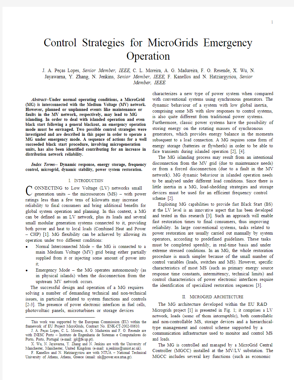
The MG architecture developed within the EU R&D Microgrids project [1] is presented in Fig. 1; it comprises a LV network, loads (some of them interruptible), both controllable and non-controllable MS, storage devices and a hierarchical-type management and control scheme supported by a communication infrastructure used to monitor and control MS and loads.
The MG is controlled and managed by a MicroGrid Central Controller (MGCC) installed at the MV/LV substation. The MGCC includes several key functions (such as economic
Control Strategies for MicroGrids Emergency
Operation
J. A. Pe?as Lopes, Senior Member, IEEE, C. L. Moreira, A. G. Madureira, F. O. Resende, X. Wu, N.
Jayawarna, Y. Zhang, N. Jenkins, Senior Member, IEEE, F. Kanellos and N. Hatziargyriou, Senior
Member, IEEE
C
managing functions and control functionalities) and heads the hierarchical control system. At a second hierarchical control level, controllers located at loads or at groups of loads (Load Controllers – LC) and controllers located at MS (Microsource Controllers – MC) exchange information with the MGCC and control local devices. LC serve as interfaces to control loads through the application of an interruptibility concept, and MC control microgeneration units, for example in terms of active
and reactive power production levels.
Fig. 1. MG architecture, comprising MS, loads and control devices
III. M ICRO G RID C ONTROL F OR I SLANDED O PERATION
In this section different approaches to deal with MG
islanded operation are described. In the first approach, the
main concern is related to inverter control modes. As the MG
is an inverter dominated grid, frequency and voltage control
during islanded operation is performed through inverters. In
this case, the main issue is how to get a voltage and frequency
reference in the islanded MG. The other approach closely
follows concepts related to conventional synchronous machine
control.
A. MicroGrid Operation Regarding Inverters Control Modes
The approach focused on inverter control modes required
the modelling of MS and storage devices, as well as inverters.
MG loads are modelled as a combination of impedance type
and induction motor type loads. Load shedding mechanisms
based on MG frequency deviation were also considered to be
implemented in the LC.
1) Microsource and Storage Devices Modelling
Several MS models have been developed including fuel-
cells, microturbines, wind generators and photovoltaic arrays
[5]. A Solid Oxide Fuel-Cell (SOFC) was used in this
research. Its model includes a Fuel Processor, which converts
fuels like natural gas to hydrogen, a Power Section, where
chemical reactions take place, and a Power Conditioner that
converts DC to AC power. More details about the used
dynamic model of the SOFC can be found in [6] and [7].
The GAST dynamic model [6] was adopted for the primary
unit of microturbines, since they are small simple-cycle gas
turbines. Both high-speed single-shaft units (with a
synchronous machine) and split-shaft units (using a power
turbine rotating at 3000 rpm and a conventional induction
generator connected via a gearbox) were modelled. The
single-shaft unit requires an AC/DC/AC converter for grid
connection. The wind generator is considered an induction
machine directly connected to the network. Concerning the
PV generator, it was assumed that the array is always working
at its maximum power level for a given temperature and
irradiance. Basically, it is an empirical model based on
experimental results as described in [5], where a detailed
description on MS modelling adopted in the Microgrids
project can also be found.
Considering the time period under analysis, storage
devices, such as flywheels and batteries, are modelled as
constant DC voltage sources using power electronic interfaces
to be coupled with the electrical network (AC/DC/AC
converters for flywheels and DC/AC inverters for batteries).
2) Inverter Modelling
Two kinds of control strategies may be used to operate an
inverter [8]. The inverter model is derived according to the
control strategy followed:
?PQ inverter control: the inverter is used to supply a given
active and reactive power set-point;
?Voltage Source Inverter control logic: the inverter is
controlled to “feed” the load with pre-defined values for
voltage and frequency. Depending on the load, the
Voltage Source Inverter (VSI) real and reactive power
output is defined.
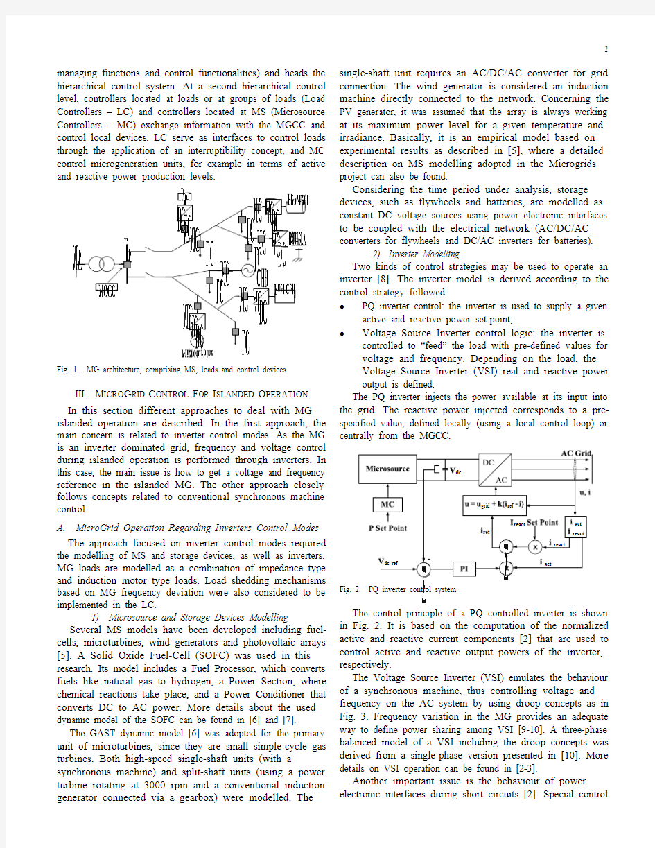
The PQ inverter injects the power available at its input into
the grid. The reactive power injected corresponds to a pre-
specified value, defined locally (using a local control loop) or
centrally from the MGCC.
Fig. 2. PQ inverter control system
The control principle of a PQ controlled inverter is shown
in Fig. 2. It is based on the computation of the normalized
active and reactive current components [2] that are used to
control active and reactive output powers of the inverter,
respectively.
The Voltage Source Inverter (VSI) emulates the behaviour
of a synchronous machine, thus controlling voltage and
frequency on the AC system by using droop concepts as in
Fig. 3. Frequency variation in the MG provides an adequate
way to define power sharing among VSI [9-10]. A three-phase
balanced model of a VSI including the droop concepts was
derived from a single-phase version presented in [10]. More
details on VSI operation can be found in [2-3].
Another important issue is the behaviour of power
electronic interfaces during short circuits [2]. Special control
functions and sufficient oversizing is required because, in contrast to synchronous generators, power electronics have no thermal short-term overloading capabilities. The current limiting function is easily implemented in the PQ controlled inverters by limiting the total gain of the PI controllers shown in Fig. 2 In order to limit the output current of a VSI, a control technique like the one presented in Fig. 2 is also used. The main difference is that in this case the reference current has a maximum peak value dependent on switching devices characteristics and its frequency is imposed by the inverter
frequency/active power droop.
Fig. 3. Frequency / active power droop characteristic
3) Control Schemes for MicroGrid Islanded Operation
If a cluster of MS is operated within a MG and the main power supply (the MV network) is available, all the inverters can be operated in PQ mode, because there are voltage and frequency references. However, a VSI can be used to provide a reference for frequency and it will be possible to operate the MG in islanded mode and to smoothly move to islanded operation without changing the control mode of any inverter [2-3]. After identifying the key solution for MG islanded operation, two main control strategies are possible: ?Single Master Operation (SMO): A VSI is used as voltage reference when the main power supply is lost (in
order to balance local load and generation); all other inverters can then be operated in the PQ mode;
?Multi Master Operation (MMO): More than one inverter is operated as a VSI. However, other PQ controlled inverters may coexist.
During islanded operation, the power injected by the storage devices is proportional to MG frequency deviation. Therefore, correcting permanent frequency deviation during islanded operation should be considered a key objective in any control strategy in order to avoid storage devices to keep injecting (or absorbing) active power whenever MG frequency deviation differs from zero [2-3]. The combination of primary frequency regulation provided by storage devices, load shedding schemes for less important loads and secondary load frequency control are the key for successful MG islanded operation.
B. MicroGrid Operation Regarding Primary Energy Source Control
In this representation, the MS and storage device (flywheel) can be represented by synchronous generators or by STATCOM Battery Energy Storage (STATCOM-BES). In grid-connected mode, the frequency of the MG is maintained within a tight range. However, following a disturbance, the frequency of the MG may change rapidly due to the low inertia present in the MG. The control of the MS and storage devices (flywheel) is very important in order to maintain the frequency of the MG during islanded operation. The controllers of MS and flywheel inverters respond in milliseconds. For basic operation of the MG, the controllers should use only local information to control the flywheel and MS.
1) Local Frequency Control Strategies
The possible control strategies of the MS and the storage device may be:
?PQ control (fixed power control);
?Droop control;
?Frequency/Voltage control.
PQ control is adopted so that the MS and the flywheel run on constant power output. The electricity generated by the MS may have to be constant because of the needs of the related thermal loads. In addition, the power output of the flywheel may be fixed at zero when the MG is operated in grid-connected mode. As PQ control delivers a fixed power output, it makes no contribution to local frequency control of the MG. Therefore, the control scheme of the flywheel has to be changed from PQ control to droop control or frequency/voltage control during islanded operation. Droop control is similar to the function of primary frequency control in a conventional synchronous generator. The frequency of the MG can be restored to a steady-state value determined by the droop characteristic. Frequency/voltage control is similar to the function of secondary frequency control in the conventional synchronous generator. The power output of the flywheel is regulated according to predetermined droop characteristics.
With droop control action, a load change in the MG will result in steady-state frequency and voltage deviations, depending on the droop characteristics and frequency/voltage sensitivity of the load. The flywheel will contribute to the overall change in generation. Restoration of the frequency/voltage of the MG to their normal values requires a supplementary secondary frequency control action to adjust automatically the output of the flywheel.
IV. M ICRO G RID B LACK S TART
The MicroGrid Black Start functionalities were developed using the control strategy described in section III.A. During normal operation, the MGCC periodically receives information from the LC and MC about consumption and power generation levels, storing this information in a database. Information about technical characteristics of the different MS in operation is also stored. MG Black Start involves the identification of a set of rules and conditions to be checked during the restoration stage, which should be identified in advance and embedded in the MGCC software. The implementation of a BS procedure requires the availability of some MS with BS capability, which involves an autonomous local power supply to feed local auxiliary control systems and launch MS generation. During the restoration of the LV
network, the storage will also contribute to face load-tracking problems, since some microgenerators (fuel-cells,
microturbines) have a slow response and are inertia-less. For the development of the BS procedure it was assumed that MS
with BS capability are the single-shaft microturbine (SSMT), the SOFC and the storage device. MS with BS capability should have batteries in their DC bus. It was also assumed that, at least during the first stages of this sequence, a multi master control approach is adopted, being switched to SMO in the final stages of the BS procedure. The strategies to be
followed make use of the hierarchical control system of the
MG, namely of LC, MC and the MGCC.
A. Sequence of Actions for MicroGrid Black Start
After a system blackout, the MGCC will try to restore the last MG load scenario. The main problems to deal with during the restoration procedure include building the LV network, connecting microgenerators, controlling voltage, controlling frequency and connecting controllable loads. Considering these problems the following sequence of actions for MG restoration should be carried out [3]:
- Disconnection of all loads in order to avoid large frequency
and voltage deviations when energizing the network. The MG should also be sectionalized around each MS with BS capability in order to allow it to feed its own (protected) loads. - Building the LV network. The inverter associated with the storage device will be responsible for LV and Distribution Transformer (DT) energization. In order to follow the earthing LV protection guidelines, the MG should keep the earth reference, available in the earth connection of the neutral of the DT. Therefore, when building the LV network it is necessary to energize the DT as soon as possible. When energizing the DT by the LV side, a large inrush current is experienced. In order to overcome this problem, transformer energization should be performed using a ramp-wise voltage wave form. - Small islands synchronization. MS already in operation in stand alone mode should be synchronized with the LV network. The synchronization conditions (phase sequence, frequency and voltage differences) should be verified by local MC in order to avoid large transient currents. - Connection of controllable loads to the LV network is performed if the MS running in the LV network have the capacity to supply these loads taking into account the available energy storage. - Connection of non-controllable MS or MS without BS
capability, like PV and wind generators.
- Load increase. In order to feed as much load as possible, depending on production capability, other loads can now be connected.
- Change the control scheme of the inverters: after service restoration on the MG, the control schemes of the SSMT and SOFC inverters are changed from VSI to PQ control. This is
required because batteries that are assumed to be installed in
the DC link of these MS are not suitable to respond to frequent
load variations, since charge and discharge cycles reduce significantly their life-cycle. On the other hand, flywheel life is almost independent of the depth of discharge. Flywheel storage systems can operate equally well on frequent shallow discharges and on very deep discharges. - MG synchronization with the MV network when it becomes
available. The synchronization conditions should be verified again.
National Technical University of Athens (NTUA) developed an approach for MG service restoration based on similar concepts and making use of a Multi Agent System (MAS). An important issue is that both procedures have a common rational due to the specific nature of the MS and to the dimension of the MG. The general idea is that the agents
will execute all the necessary actions (decided in advance)
without human interaction. This approach has two main
advantages. The first advantage is that the computational
demand during the critical event is limited and this is very important considering that the time limits are very strict and the processors that will be used in a future MG are not powerful supercomputers, as in large centralized power systems. The second advantage lies in the fact that during the black out there are several communication problems that can be avoided by using a MAS. Therefore the data exchange should be even more limited. V. M ICRO G RID S IMULATION P LATFORMS A simulation platform under the Matlab/Simulink environment was developed to study the dynamic behaviour of several MS operating together in a LV network and controlled according to what was described in section III.A . The fast transients associated with the initial moments of the MG restoration procedure were studied in another simulation platform developed in EMTP-RV , where the switching details of the power electronic interfaces were included. The longer term dynamic behavior of the MG during the restoration procedure was also evaluated using the Matlab/Simulink platform. As an illustrative example, Fig. 4 shows the study case LV network in the Matlab/Simulink simulation platform. Another simulation tool was also developed in PSCAD/EMTDC to evaluate MG control functionalities described in section III.B . Two situations were assumed:
? MS and the storage device represented by synchronous generators;
? MS and storage represented by STATCOM-BES devices. Again, the purpose of this approach was to evaluate the robustness of the control schemes adopted. VI. R ESULTS A ND D ISCUSSION This section includes results showing the dynamic behaviour of the MG (using the different control approaches previously described) during and subsequent to the islanding
process. Results describing the fast and long term dynamic behaviour obtained in the MG during the adopted BS sequence are also described next. A. Moving to Islanded Operation
Disconnection from the upstream MV network and load-following in islanded operation was simulated using a SMO control strategy described in the section III.A . The scenario is characterized by a local load of 80 kW (65% of impedance type and 35% of induction motor type) and a local generation of 50 kW. A fault occurred at t=10s in the MV network
followed by MG islanding, 100 milliseconds after.
Due to the large initial frequency deviation, an amount of load was automatically shed through the activation of load shedding relays in order to aid frequency restoration. This load was later reconnected in small load steps (Fig. 5). MS selected for the secondary load-frequency control (the SOFC and the SSMT) participate in frequency restoration using a proportional integral control strategy in the MC. The large
time constants of the MS lead to a relatively slow process for
restoring frequency to its nominal value.
From the frequency behaviour, it may be observed that MG
stability is not lost when facing the short-circuit at the MV
grid side. Speed rotation of motor loads drops considerably during the fault, which has a great impact in the MG current
and voltage after fault elimination, as can be observed in Fig. 6. The principles presented for current limitation in VSI can
also be observed in Fig. 6. Fig. 4. LV test network in the Matlab/Simulink simulation platform
Fig. 7 shows the response of the MG when the control strategy described in section III.B is used and the MS are represented as STATCOM-BES. The flywheel is using frequency/voltage control during islanded mode. Results have shown that after intentional disconnection of the MG from the main network at t=10s, the output of the MS is still retained at 30 kW. However, the output of flywheel is changed from zero to around 180kW+j120kvar. Due to the frequency/voltage control, the frequency and voltage of the MG are restored to the nominal values.
B. MicroGrid Black Start In order to study this case it was assumed that a general collapse took place and was followed by: a) the disconnection from the MV grid of the MV/LV transformer; b) the disconnection of loads and c) the automatic creation of islands operating in standalone mode to supply protected loads associated with the SSMT and the SOF
C.
F r e q u e n c y (H z )
V S I P & Q (k W / k v a r )
Time (s)
P (k W )
Fig. 5. MG Frequency, VSI active and reactive power and SOFC and single-shaft microturbine active power
V S I C u r r e n t (A )
Time (s)
V S I V o l t a g e (V )
Fig. 6. VSI current and voltage during and after the fault
Network behaviour during BS initial stages was evaluated with the EMTP-RV platform described in [3], including in this case the fast inverter commutation transients. The VSI shown in Fig. 4 was selected for energizing the LV network and the MV/LV transformer, at t=0.2s, using a voltage ramping control during 0.5s to reduce the magnetizing current of the DT. The inverter current thus obtained is presented in Fig. 8 where it is possible to observe that the DT magnetizing current was kept at low values.
In order to get an extended overview of the long term dynamic behaviour induced by the overall BS procedure, the MatLab/Simulink simulation platform was used. The simulations starts considering that the MS are feeding the
protected loads and the LV network and the DT are energized. The sequence of actions involves:
? Synchronizing the SOFC with the LV network (t=12.8s) ? Synchronizing the SSMT with the LV network (t=30.6s) ? Starting-up of a motor load (t=50s) ? Connecting the wind generator (t=71s) ? Connecting controllable loads (t=100s) ? Connecting the PV (t=120s)
? Connecting controllable loads (t=140s)
? Changing the SSMT and SOFC inverters to PQ control
(t=165s and t=170s respectively)
?
Synchronizing the MG with the MV network
Fig. 7. Dynamic performance of the MG (using STATCOM-BES
representation)
Fig. 8. Storage inverter current during initial BS stages Fig. 9 shows the impact of the referred sequence of actions in frequency and MS active power production levels.
Frequency deviation after load reconnection was identified to be a critical issue in this procedure, requiring a special attention. If a frequency deviation remains for some time, a local secondary control was used to restore frequency to the nominal value.
M G F r e q u e n c y (H z
)
P - S t o r a g e (k W )
Time (s)
M S - P (k W )
Fig. 9. MG frequency and MS active power
VII. C ONCLUSIONS
Simulation results indicate that MG islanding can be performed satisfactorily even after a fault in the upstream MV network. Storage devices are absolutely essential to implement successful control strategies for MG islanded operation; the load-shedding procedure is also very important to avoid fast and long frequency deviations.
Rules and conditions to be checked during the restoration stage by the MG components were derived and evaluated through numerical simulation, proving the feasibility of such procedures.
VIII. R EFERENCES
[1] European Research Project MicroGrids [Online]. Available:
http://microgrids.power.ece.ntua.gr/ [2] J. A. Pe?as Lopes, C. L. Moreira and A. G. Madureira, “Defining control
strategies for analysing microgrids islanded operation”, in Proc. IEEE St. Petersburg PowerTech 2005, Russia.
[3] J. A. Pe?as Lopes, C. L. Moreira and F. O. Resende, “MicroGrids black
start and islanding operation”, in Proc. 15th PSCC, Belgium, 2005.
[4] R. Lasseter and P. Piagi, “Providing premium power through distributed
resources”, in Proc. 33rd Hawaii International Conference on System Science, vol. 4, Jan. 2000.
[5] N. Hatziargyriou et al ., “Modelling of Micro-Sources for Security
Studies”, Proc. CIGRé 2004 Conf., France, Aug. 30–Sept. 3, 2004.
[6] Y. Zhu and K. Tomsovic, “Development of models for analysing the
load-following performance of microturbines and fuel cells”, Electric Power Systems Research, vol. 62, no. 1 , pp. 1-11, May 2002.
[7] J. Padullés, G.W. Ault and J. R. McDonald, “An integrated SOFC plant
dynamic model for power systems simulation”, Journal of Power Sources, vol. 86, no. 1-2, pp. 495-500, March 2000.
[8] S. Barsali, M. Ceraolo and P. Pelacchi, “Control techniques of Dispersed
Generators to improve the continuity of electricity supply”, in Proc. of PES Winter Meeting, vol. 2, pp. 789-794, 2002.
[9] M. C. Chandorkar, D. M. Divan and R. Adapa, “Control of parallel
connected inverters in standalone AC supply systems”, IEEE Transactions on Industry Applications, vol. 29, no. 1, Jan. – Feb. 1993. [10] A. Engler, “Applicability of droops in low voltage grids”, International
Journal of Distributed Energy Resources, vol. 1, no. 1, Jan.-Mar. 2005.
---------------------- 前台规章制度 一、仪容仪表 1. 上班时间需化淡妆,长发须佩戴头花或盘起。 2. 着装必须干净整洁,必须穿工作服上班。 3. 不能留长指甲,不能涂指甲油,不能佩戴夸张的饰品。 4. 保持最佳的精神状态工作。 二、工作纪律 1. 上班时间,不能吃东西、上网看电视,打接与工作无关的电话时间不能过长(特殊情况和家里重大事情除外)。 2. 上班时间不能在前台睡觉、不能串岗、不能拿上班时间会客,不能大声喧哗。 3.上班时间不能无故缺席,离岗时要在登记表做好记录(楼层巡检,吃饭,检查各个会议室等)不得无故闲逛。 三、工作规定 1. 上班期间服务态度好。主动向客人问好、站立服务、耐心的与客人交流,让客人在酒店住的舒适。 2. 员工不能把私人情绪带入工作中,随时随地对客人保持微笑。 3. 不能拿酒店财物私用或带回家(如有发现一律重罚或开除)。 4. 时刻保持前台的清洁。 5. 员工不能徇私舞弊,互相包庇。 6. 当班人员上班,不能迟到早退、不能擅自离岗、不能私自换班(需提前报告领导写好换班条,待领导审批,通过方可换班)、不能无故旷工(特殊情况可向部门领导请示)。 以上规章制度一经核实,发现第一次给予警告,第二次给予罚款,犯多次或屡教不改者,公司有权给予开除处理。 备注:(罚款方式:第一次20元,第二次50元,情况严重者重罚) ---------------------------------------------------------精品文档
---------------------- ---------------------------------------------------------精 品 文档前台工作内容 1. 为客人办理入住登记并请客人签字确认,认付款方式(挂账、现金,)问明付过押金后给客人房卡,并向客人解释房卡内容,在电脑中及时占房,发放早餐卷。 2.住宿登记单上,住几个人写几个人的名字,以便开门。入住时要询问客人住几天,以便刷几天的房卡,收几天的房费。同时,电脑上时间也要与此一致, 以方便楼层。坚持姓氏称呼。 3.阅读交班本,了解上一班未完成事项,及时进行跟进和处理。 4.查看各部门钥匙使用和归还纪录情况,并将钥匙分类放置。 5.核对房态,确保房态正确,清点房卡,所有一致加起来数目和上一班交接相符和。 6.如有客人要求换房,确定已通知客房服务人员和楼层服务人员进行打扫,检查。确认无误,收回房卡,发放新的发卡为客人换房。 7.了解每日会议信息和会议用房数,若会议举办方有任何要求,及时与楼层服务员和客房服务 员联系并跟进。
酒店房卡管理规定 一、房卡类别 1、客房房卡分总控卡、领班卡、楼层卡、客人卡。 2、总控卡由相关管理人员持有。 3、领班卡由各楼层领班持有。 4、楼层卡各楼层员工持有。 5、客人卡由前台员工保管、制作。 注:若领班卡、楼层卡丢失或损坏,应立即上报部门,采取相应的措施(消磁和补办),当班人员要有补办记录,以免酒店遭受损失 二、房卡管理 1、总控卡由总经理、副总经理、前厅部经理、客房部经理、大堂经理持有。 2、领班卡、楼层卡由客房服务中心保管,实行每天签字借用制度。 ⑴领班卡用于查房使用,此卡可以开启所管辖的楼层所有客房房门。 ⑵楼层卡用于服务员打扫卫生使用,按照服务员的工作范围制作。 ⑶调换楼层时要有交接手续。
3、持卡人不得将自己的卡借给其他人员使用,一定发现必将严惩。 4、客人卡的管理制度: ⑴将客房卡交给客人前,前台员工必须确认客人身份; ⑵前台原则上单人房每间只发放一张房卡,双人房根据客人要求可发放两张房卡,并在电脑中注明数量; ⑶客人房卡遗失: 验明客人身份和登记相符→说明规定,向客人收取或从押金中扣除赔偿费→重新制作l张新的房卡给客人→确保前一张房卡作废。 ⑷客人钥匙损坏: A. 验卡→显示房号和客人所报相同,且在期限内→重新制作一张房卡给客人,并与客人说明赔偿费用。 B. 如果卡号不能显示或不能验卡→验明客人身份和登记相符→重新制作1张房卡给客人,并向客人说明赔偿费用。 ⑸客人寄存钥匙: A. 听清客人所报房号,请客人稍等→验卡→显示房号和客人所报一致,取房卡袋填写房号,将房卡插入房卡袋内,放在抽屉内→客人来取时,验明身份后,交还房卡。 B. 如验卡时,房号不能显示,应先验明身份,再进行寄
酒店前台房卡管理规定 SANY GROUP system office room 【SANYUA16H-
前台房卡管理规定 一、房卡类别: 1、客房房卡分总控卡、领班卡、楼层卡、客人卡。 2、总控卡店级领导、客房相关管理人员持有(董事长、总经理、副总经理、客务总监、客房经理) 3、领班卡由各楼层领办持有 4、楼层卡各楼层员工持有 5、客人卡由前台员工制作 注:若领班卡、楼层卡丢失或损坏,应立即上报部门,采取相应的措施(消磁和补办),前台要有补办记录,以免酒店遭受损失 二、客人卡的管理制度: 1、将客房匙交给客人前,前台员工必须确认客人身份; 2、前台原则上单人房每间只发放一条房匙,双人房根据客人要求可发放两条房匙,并在电脑中注明; 3、客人房卡遗失: 验明客人身份和登记相符→说明规定,向客人收取或从押金中扣除赔偿费(30元)→重新制作l把新的钥匙给客人→通知房务中心→使用管理卡到该房间插一次卡(做消磁处理),确保插卡前使用的钥匙作废。 4、客人钥匙损坏: A.验卡→显示房号和客人所报相同,且在期限内→重新制作l把钥匙给客人,并向客人致歉。 B.如果卡号不能显示或不能验卡→验明客人身份和登记相符→重新制作1把钥匙给客人,并向客人致歉。 5、客人寄存钥匙: A.听清客人所报房号,请客人稍等→验卡→显示房号和客人所报一致,取房卡填写房号,钥匙插入新房卡,放在寄存抽屉内→客人来取时,验明身份后,交还钥匙,将写房号的房卡撕毁。 B.如验卡时,房号不能显示,应先验明身份,重新制作钥匙,再进行寄存。 C.如客人寄存时嘱咐他人来取→填写留言单,请客人签字确认→钥匙、留言单放在房卡中存放于收银抽屉内→领取时验明身份→留言单保留在客帐内直至客人退房。 6、客人退房时,前台员工应提醒客人交还房匙→如客人出示的钥匙没有房卡或押金单证明其房号,必须验卡验证无误后,方可通知客房服务员查房并办理退房手续。 7、退房时,客人将钥匙留在房间:客房服务员查完房交到前台。凡有折痕、断裂、明显污迹、坏的钥匙,交前台主管保管。
酒店前台房卡管理 一、房卡类别及制卡权限: 1、客房房卡分总卡、领班卡、楼层卡、客人卡 2、总卡为客房相关管理人员持有(董事长、总经理、副总经理、客务总监、客 房经理、前厅经理)由前厅经理制作 3、领班卡由各楼层领办持有由大堂副理或前厅经理制作 4、楼层卡各楼层员工持有由大堂副理制作 5、客人卡由前台员工制作 二、客人卡的管理制度: 1、将房卡交给客人前,前台员工必须确认客人身份; 2、前台原则上单人房每间只发放一张房卡,双人房根据客人要求可发放两张房 卡,并在电脑中注明; 3、客人房卡遗失: 验明客人身份和登记相符→说明规定,向客人收取或从押金中扣除赔偿费(50元)→重新制作一张新的房卡给客人→通知房务中心→使用管理卡到该房间插一次卡(做消磁处理),确保插卡前使用的房卡作废。 4、客人房卡损坏: 1)验卡→显示房号和客人所报相同,且在期限内→重新制作一张房卡给客人, 并向客人致歉。 2)如果房卡号不能显示或不能验卡→验明客人身份和登记相符→重新制作一 张房卡给客人,并向客人致歉。
5、客人寄存房卡: 1)听清客人所报房号,请客人稍等→验卡→显示房号和客人所报一致,取 房卡套填写房号,房卡插入房卡套,放在寄存抽屉内→客人来取时,验明身份后,交还房卡,将写房号的房卡套撕毁。 2)如验卡时,房号不能显示,应先验明身份,重新制作房卡,再进行寄存。 3)如客人寄存时嘱咐他人来取→填写留言单,请客人签字确认→房卡、留 言单放在房卡中存放于收银抽屉内→领取时验明身份→留言单保留在客帐内直至客人退房。 6、客人退房时,前台员工应提醒客人交还房卡→如客人出示的房卡没有房卡 或押金单证明其房号,必须验卡验证无误后,方可通知客房服务员查房并办理退房手续。 7、退房时,客人将房卡留在房间:客房服务员查完房交到前台。凡有折痕、断 裂、明显污迹、坏的房卡,交前台主管保管并做记录。 8、未经登记客人许可,不得为任何来访者开启客人房间或发卡给来访者; 9、任何服务员如发现房卡遗留于公共场所,应立即交当值主管,送回前台接待 处处理; 10、客房服务员不得对客人以错放房卡在房间内为由,随便开房门让客人进入, 应即时打电话到前台接待处核实客人身份,如有任何疑问,应请客人到前台接待处办理补卡手续。 11、前台服务员每班交接时,必须核对客人房卡数量。发现任何缺失必须上报 并在交接本上作记录。 12、所有房卡上不能贴房号
星级酒店房卡管理制度4 一、房卡类别: 1、客房房卡分总控卡、领班卡、楼层卡、客人卡。 2、总控卡店级领导、客房相关管理人员持有(董事长、总经理、副总经理、客务总监、客房经理) 3、领班卡由各楼层领办持有 4、楼层卡各楼层员工持有 5、客人卡由前台员工制作 注:若领班卡、楼层卡丢失或损坏,应立即上报部门,采取相应的措施(消磁和补办),前台要有补办记录,以免酒店遭受损失 二、客人卡的管理制度: 1、将客房匙交给客人前,前台员工必须确认客人身份; 2、前台原则上单人房每间只发放一条房匙,双人房根据客人要求可发放两条房匙,并在电脑中注明; 3、客人房卡遗失: 验明客人身份和登记相符→说明规定,向客人收取或从押金中扣除赔偿费(30元)→重新制作l把新的钥匙给客人→通知房务 中心→使用管理卡到该房间插一次卡(做消磁处理),确保插
卡前使用的钥匙作废。 4、客人钥匙损坏: A.验卡→显示房号和客人所报相同,且在期限内→重新制作l把钥匙给客人,并向客人致歉。 B.如果卡号不能显示或不能验卡→验明客人身份和登记相符→重新制作1把钥匙给客人,并向客人致歉。 5、客人寄存钥匙: A.听清客人所报房号,请客人稍等→验卡→显示房号和客人所报一致,取房卡填写房号,钥匙插入新房卡,放在寄存抽屉内→客人来取时,验明身份后,交还钥匙,将写房号的房卡撕毁。 B.如验卡时,房号不能显示,应先验明身份,重新制作钥匙,再进行寄存。 C.如客人寄存时嘱咐他人来鳃填写留言单,请客人签字确认→钥匙、留言单放在房卡中存放于收银抽屉内→领取时验明身份→留言单保留在客帐内直至客人退房。 6、客人退房时,前台员工应提醒客人交还房匙→如客人出示的钥匙没有房卡或押金单证明其房号,必须验卡验证无误后,方可通知客房服务员查房并办理退房手续。 7、退房时,客人将钥匙留在房间:客房服务员查完房交到前台。凡有折痕、断裂、明显污迹、坏的钥匙,交前台主管保管。 8、未经登记客人许可,不得为任何来访者开启客人房间或
客房部房卡管理制度及开门程序 房卡管理制度 1、作为客房部的任何一员,如将总卡或是楼层卡丢失,就等于丢掉自己的这份工作,后果是不堪设想的,因为这关系到酒店和客人的财产安全和人生安全问题; 2、所有持卡人都应做到卡不离人,不可将卡乱扔乱放,更不可 将卡随便给部门以外的人去开房门; 3、每天上下班或吃饭的时候,都应有交接卡的程序,做好交接 的登记; 4、不可将卡带离工作岗位,用餐或下班时应将卡交还房务中心保管; 5、每个持卡人都应爱护房卡,正确使用房卡。 敲门开门程序 1、客房部任何持卡人都应养成,不管是任何房态(也就是说: 不管是空房、住人房、锁房还是维修房等等”)都应养成敲门报服务员”的好习惯; 2、在开房门前首先要时刻了解所要开门的房间状态(即:房态),一般除住人房而外,我们只需敲一次房门报服务员”即可,而对 住客房来讲就不能简单化,不管此时房间是否有客或是无客,都应先按门铃三下或再敲三次房门,然后报:服务员”同时耳朵 要时刻关注房间有无动静(也就是说:是否听到有客人回应?”; 3、不可不敲门直接就拿房卡开门,或者是边敲门边插房卡开门,
还有任何人都不能抱有:我以为房间没有客人”的这种想法,而 直接插卡开门的话,将会酿成大错,这些可都是开门的大忌; 4、开门时要注意房卡芯片的朝向,同时要懂得识别电脑锁信号灯所表示的意思,电脑锁信号灯一般有以下四种表示意义: A、房卡芯片朝向正确和设置房号和门牌号对得上,插入房卡电脑锁会亮绿灯,你会听到嘟”一声,此时立即拔出房卡,此时又会听到电脑锁内弹簧回弹的声音,这时房门就可以打开了; B、房卡所设置的房号与门牌号对不上(也就是说:客人如果走错房间”,或者是房卡超时和插卡不到位,此时电脑锁会闪三下黄灯,房门是打不开的; C、任何房卡插反了,电脑锁都会亮红灯,抽出房卡红灯立即熄 灭,此时房门是打不开的; D如果房间里面打上防盗栓的话,此时用总卡、楼层卡、宾客卡开门,电脑锁都会先亮黄灯,再亮红灯,并且会有嘟”一声鸣响; E、不管你怎么插卡,电脑锁都不会亮灯的话,表示电脑锁没有电了,就要采取措施更换电池,方可用卡开门。 5、客房部任何持卡人都不能随便用自己的卡去帮客人开门,必 须确认客人身份无误后,方可用自己的卡帮客人开门,一般客人开不了门并要求帮其开门有以下几种情况: A、客人有卡,没欢迎卡,走错房间; B、客人有卡,有/无欢迎卡,但客人不会开;
南融全际酒店 房卡管理制度 一、房卡类别: a)客房房卡分总裁卡、管理卡、总控卡、领班卡、楼层卡、客人卡。 b)总裁卡、管理卡、总控卡由总经办班相关管理人员持有(总经理、总助) c)领班卡由客房经理和客房主管、领班持有 d)楼层卡由各楼层客房部员工持有 e)客人卡由前台员工制作 注:若领班卡、楼层卡丢失或损坏,应立即上报直属上级,采取相应措施(消磁 和补办),前台需有补办记录,以免酒店遭受损失 二、房卡操作流程 a)领班卡、楼层卡由客房部负责保管,必须存放在指定地方,客房经理须每天检查 b)楼层房卡由客房经理/主管在每日晨会时发放给服务员 c)服务员在领用和交接时必须在工作记录本上记录并签名确认 d)服务员在当班时才有权使用楼层卡在班次结束时需将楼层卡归还 e)服务员非工作需要不得擅自开启客房房门 f)不得随便为他人开启客房 g)客人在楼层要求开门,服务员请客人核对身份,用电话和前台核对(姓名、身份证、 入住日期等),待确认客人身份后方可为客人开启房门 h)按前台指示为客人开启房门 三、房卡保管 a)房卡要时刻随身携带,不得乱丢、乱放 b)严禁将房卡转借他人使用 c)丢失房卡,马上报告主管,查明原因,积极寻找 d)房卡严禁当取电卡使用 e)夜班员工领取领班卡 f)房卡归还必须有记录,并且签名确认 四、客人卡管理制度 a)客人入住前前台人员将客人房间房卡制作给客人 b)原则上每个房间只发放一张房卡,若客人需要两张房卡需收取相应的押金为客人发 放两张房卡并在电脑上注明,在交班记录本上做好交接 c)客人房卡遗失:验明客人身份和登记相符说明规定,向客人收取赔偿费重 新制作一把新的房卡给客人开具赔偿单签客人签字在交班记录本上做好 交接管理人员根据赔偿单到财务处领取新房卡 d)客人房卡损坏:验卡显示房号和客人所报相同,且房卡还未过期核对客
客房服务流程及规范 一、目的:为了规范客房服务人员的服务行为,提高酒店的客房服务水平, 提升客户对服务的满意度,特制定工作标准。 二、员工仪容仪表: 1.手指甲不得超过0、5毫米,时刻保持清洁,不可涂指甲油; 2.经常理发,头发梳理整齐。保持前不遮眉、中不盖耳、后不过领,女士 长发要简单盘于脑后。男士胡须应始终修剪干净。 3.不可佩戴夸张首饰,男士只可带样式简单的手表; 4.整齐穿着酒店制服,制服要求干净整洁; 5.员工不可佩戴有色及大框眼镜; 6.女员工必须着淡妆,不可不化妆或化浓妆。 三、对客服务规范: 1.见到客人要侧身礼让并微笑点头问好; 2.与客人交谈时要有礼貌,必须使用礼貌用语; 3.对客人的额外要求,应立即报告主管; 4.不得向客人索要小费或礼品; 5.如果发现客人在房间里吵闹、发病或醉酒,立即通知主管; 6.非工作需要不得开启或进入客人房间,如因工作需要应先敲门经客人 允许后方可进入; 7.在客人房间做清洁时,不得翻瞧客人物品; 8.不得想客人泄露酒店管理秘密; 9.不得想客人泄露其她客人的信息及秘密; 10.不得私自为客人结账,应礼貌指引到前厅处。 四、物品发放流程及规范: 1.填写申请单 ①客房部凡领用物品,均须规定填写申请单; ②申请单须经主管与经理审批。 2.发放与盘点 ①凭经理审批后的申请单,有客房文员予以发放,发货时要注意物品 保质期,先进先发、后进后发; ②客房文员按时进行月度物品盘点存量。 3.做好发放记录 ①发放物品时,客房文员要以填好的物品领用单(含日期、名称、规 格、型号、数量、单价、用途等)为依据; ②客房文员要及时做好物品管理账簿,保证账物一致。
酒店前台房卡管理制度 一、房卡类别: 1、客房房卡分总控卡、领班卡、楼层卡、客人卡。 2、总控卡店级领导、客房相关管理人员持有(董事长、总经理、副总经理、客务总监、客房经理) 3、领班卡由各楼层领班持有 4、楼层卡各楼层员工持有 5、客人卡由前台员工制作 注:若领班卡、楼层卡丢失或损坏,应立即上报部门,采取相应的措施(消磁和补办),前台要有补办记录,以免酒店遭受损失 二、客人卡的管理制度: 1、将客房匙交给客人前,前台员工必须确认客人身份; 2、前台原则上单人房每间只发放一条房匙,双人房根据客人要求可发放两条房匙,并在电脑中注明; 3、客人房卡遗失: 验明客人身份和登记相符→说明规定,向客人收取或从押金中扣除赔偿费(30元)→重新制作l把新的钥匙给客人→通知房务中心→使用管理卡到该房间插一次卡(做消磁处理),确保插卡前使用的钥匙作废。 4、客人钥匙损坏: A.验卡→显示房号和客人所报相同,且在期限内→重新制作l把钥匙给客人,并向客人致歉。 B.如果卡号不能显示或不能验卡→验明客人身份和登记相符→重新制作1把钥匙给客人,并向客人致歉。 5、客人寄存钥匙: A.听清客人所报房号,请客人稍等→验卡→显示房号和客人所报一致,取房卡填写房号,钥匙插入新房卡,放在寄存抽屉内→客人来取时,验明身份后,交还钥匙,将写房号的房卡撕
毁。 B.如验卡时,房号不能显示,应先验明身份,重新制作钥匙,再进行寄存。 C.如客人寄存时嘱咐他人来取→填写留言单,请客人签字确认→钥匙、留言单放在房卡中存放于收银抽屉内→领取时验明身份→留言单保留在客帐内直至客人退房。 6、客人退房时,前台员工应提醒客人交还房匙→如客人出示的钥匙没有房卡或押金单证明其房号,必须验卡验证无误后,方可通知客房服务员查房并办理退房手续。 7、退房时,客人将钥匙留在房间:客房服务员查完房交到前台。凡有折痕、断裂、明显污迹、坏的钥匙,交前台主管保管。 8、未经登记客人许可,不得为任何来访者开启客人房间或发卡给来访者; 9、任何服务员如发现房卡遗留于公共场所,应立即交当值主管,送回前台接待处处理; 10、客房服务员不得对客人以错放锁匙在房间内为由,随便开房门让客人进入,应即时打电话到前台接待处核实客人身份,如有任何疑问,应请客人到前台接待处办理补匙手续。 11、前台服务员每班交接时,必须核对客人钥匙数量。发现任何缺失必须上报并在交接本上作记录。 10、所有IC卡上不能贴房号。
前台房卡管理规定 一、房卡类别: 1、客房房卡分总控卡、领班卡、楼层卡、客人卡。 2、总控卡店级领导、客房相关管理人员持有(董事长、总经理、副总经理、客务总监、客 房经理) 3、领班卡由各楼层领办持有 4、楼层卡各楼层员工持有 5、客人卡由前台员工制作 注:若领班卡、楼层卡丢失或损坏,应立即上报部门,采取相应的措施(消磁和补办),前台要有补办记录,以免酒店遭受损失 二、客人卡的管理制度: 1、将客房匙交给客人前,前台员工必须确认客人身份; 2、前台原则上单人房每间只发放一条房匙,双人房根据客人要求可发放两条房匙,并在电 脑中注明; 3、客人房卡遗失: 验明客人身份和登记相符→说明规定,向客人收取或从押金中扣除赔偿费(30元)→重新制作l把新的钥匙给客人→通知房务中心→使用管理卡到该房间插一次卡(做消磁处理),确保插卡前使用的钥匙作废。 4、客人钥匙损坏: A.验卡→显示房号和客人所报相同,且在期限内→重新制作l把钥匙给客人,并向客人 致歉。 B.如果卡号不能显示或不能验卡→验明客人身份和登记相符→重新制作1把钥匙给客 人,并向客人致歉。 5、客人寄存钥匙: A.听清客人所报房号,请客人稍等→验卡→显示房号和客人所报一致,取房卡填写房号, 钥匙插入新房卡,放在寄存抽屉内→客人来取时,验明身份后,交还钥匙,将写房号的房卡撕毁。 B.如验卡时,房号不能显示,应先验明身份,重新制作钥匙,再进行寄存。 C.如客人寄存时嘱咐他人来取→填写留言单,请客人签字确认→钥匙、留言单放在房卡 中存放于收银抽屉内→领取时验明身份→留言单保留在客帐内直至客人退房。 6、客人退房时,前台员工应提醒客人交还房匙→如客人出示的钥匙没有房卡或押金单证明 其房号,必须验卡验证无误后,方可通知客房服务员查房并办理退房手续。 7、退房时,客人将钥匙留在房间:客房服务员查完房交到前台。凡有折痕、断裂、明显污 迹、坏的钥匙,交前台主管保管。 8、未经登记客人许可,不得为任何来访者开启客人房间或发卡给来访者; 9、任何服务员如发现房卡遗留于公共场所,应立即交当值主管,送回前台接待处处理; 10、客房服务员不得对客人以错放锁匙在房间内为由,随便开房门让客人进入,应即时打电 话到前台接待处核实客人身份,如有任何疑问,应请客人到前台接待处办理补匙手续。 11、前台服务员每班交接时,必须核对客人钥匙数量。发现任何缺失必须上报并在交接本上 作记录。 12、所有IC卡上不能贴房号。
酒店安全管理制度 总则 一、为了加强酒店的安全监督管理,防止和减少安全事故,保障酒店、客人和员工的生命和财产安全,促进酒店经营管理的健康发展,根据《中华人民共和国安全法》和有关法律法规的规定,特制定本规定。 二、酒店设安全管理委员会,由总经理任主任委员,副主任委员由酒店副总担任,以协管酒店工保部工作。安全管理委员会其他委员由各部门负责人担任,并由总经理任命。安全管理委员会的常设办事机构为工保部,安全日常工作由工保部负责,档案管理由总经办负责。 三、各部门应根据本部门各岗位的工作特点,依照国家及行业的有关劳动安全规定及技术标准,制定和不断完善本部门各类劳动安全管理制度和操作规程。 四、各部门制定的各类劳动安全管理规章制度,须报总经办备案。 五、在发生安全事故时,可根据酒店总经理指示成立事故处理小组,并按酒店制定的《安全管理工作程序和报告制度》(见附件一)进行妥善处置。 六、酒店劳动安全实行酒店、部门、班组三级管理。 七、酒店安全管理委员会的职责: 1、组织、指导各部门贯彻落实国家的安全方针和有关政策、规定。 2、教育各部门管理人员尊章守法,带头搞好安全。 3、听取各部门安全方面的情况汇报,发现问题及时找有关人员研究解决。 4、协调各部门安全工作,调查、布置、指导、检查安全情况,发现问题立即纠正。 5、负责随时检查、通报各部门劳动安全管理的执行情况,对出现的各类不安全问题及职业伤害事故进行调查分析,并提出处理意见和整改措施。 八、部门负责人安全职责: 1、在酒店安全管理委员会的领导下,对本部门执行安全规章制度的情况进行经常性的监督检查,对各岗位、设备的安全操作和安全运行进行监督。 2、向酒店安全管理委员会提交安全书面工作意见,主要包括:针对部门的安全隐患提出防范措施、隐患整改方案、安全技术措施和经费开支计划。 3、参与制定酒店和部门防止伤亡、火灾事故和职业危害的措施及危险岗位、危险设备的安全操作规程,并负责督促实施。 4、经常进行现场安全检查,及时发现、处理事故隐患。如有重大问题,应以书面形式
房卡管理制度 1、作为客房部的任何一员,如将总卡或是楼层卡丢失,就等于丢掉自己的这份工作,后果是不堪设想的,因为这关系到酒店和客人的财产安全和人生安全问题; 2、所有持卡人都应做到卡不离人,不可将卡乱扔乱放,更不可将卡随便给部门以外的人去开房门; 3、每天上下班或吃饭的时候,都应有交接卡的程序,做好交接的登记; 4、不可将卡带离工作岗位,用餐或下班时应将卡交还房务中心保管; 5、每个持卡人都应爱护房卡,正确使用房卡。 敲门开门程序 1、客房部任何持卡人都应养成,不管是任何房态(也就是说:“不管是空房、住人房、锁房还是维修房等等”)都应养成敲门报“服务员”的好习惯; 2、在开房门前首先要时刻了解所要开门的房间状态(即:房态),一般除住人房而外,我们只需敲一次房门报“服务员”即可,而对住客房来讲就不能简单化,不管此时房间是否有客或是无客,都应先按门铃三下或再敲三次房门,然后报:“服务员”,同时耳朵要时刻关注房间有无动静(也就是说:“是否听到有客人回应?”); 3、不可不敲门直接就拿房卡开门,或者是边敲门边插房卡开门,还有任何人都不能抱有:“我以为房间没有客人”的这种想法,而直接插卡开门的话,将会酿成大错,这些可都是开门的大忌; 4、开门时要注意房卡芯片的朝向,同时要懂得识别电脑锁信号灯所表示的意思,电脑锁信号灯一般有以下四种表示意义: A、房卡芯片朝向正确和设置房号和门牌号对得上,插入房卡电脑锁会亮绿灯,你会听到“嘟”一声,此时立即拔出房卡,此时又会听到电脑锁内弹簧回弹的声音,这时房门就可以打开了; B、房卡所设置的房号与门牌号对不上(也就是说:“客人如果走错房间”),或者是房卡超时和插卡不到位,此时电脑锁会闪三下黄灯,房门是打不开的; C、任何房卡插反了,电脑锁都会亮红灯,抽出房卡红灯立即熄灭,此时房门是打不开的; D、如果房间里面打上防盗栓的话,此时用总卡、楼层卡、宾客卡开门,电脑锁都会先亮黄灯,再亮红灯,并且会有“嘟”一声鸣响; E、不管你怎么插卡,电脑锁都不会亮灯的话,表示电脑锁没有电了,就要采取措施更换电池,方可用卡开门。 5、客房部任何持卡人都不能随便用自己的卡去帮客人开门,必须确认客人身份无误后,方可用自己的卡帮客人开门,一般客人开不了门并要求帮其开门有以下几种情况: A、客人有卡,没欢迎卡,走错房间; B、客人有卡,有/无欢迎卡,但客人不会开;
一、房务部规章制度 “宾客至上、服务第一”是我们的服务宗旨:客人永远是对的,是我们的座右铭。对此,每一个前台人员务必深刻、领会、贯彻到一言一行中去。 酒店业是服务行业,我们要发扬中国传统的礼节和好客之道,树立服务光荣的思想,加强服务意识,竭力提供高效、准确、礼貌的服务,这宾客创一个“宾至如归”的境界。 1)仪表、仪态: (一)本部门员工以站立姿势服务,总台夜班员工十二点以后方坐,但若有客人前来,当即起立。 (二)在服务区域内,身体不得东歪西倒,前倾后靠,不得伸懒腰、驼背、耸肩、不得扎堆聊天。 (三)不配带任何饰物、留长指甲、女员工不得涂色在指甲上。 (四)必须佩带工号牌,工号牌应佩带在左胸处,不得任其歪歪扭扭,注意修整,发现问题及时纠正,从后台进入服务区域之前,也应检查仪容仪表。 2)表情、言谈: (一)面对客人应表现出热情、亲切、真实、友好,必要时要有同情的表情,做到精神振奋、情绪饱满、不卑不亢。(二)和客人交谈时应眼望对方,频频点头称是。 (三)双手不得叉腰,交叉腰前,插入衣裤或随意乱放,不抓头,抓痒,挖耳,抠鼻孔,不得敲桌子,鼓击或摆弄其它物品。 (四)不得哼歌曲,吹口哨,跺脚,不得随地吐痰,乱蓬蓬丢杂物,不得当众整理个人衣物,不得将任何物件夹于腋下。 (五)在客人面前不得经常看表。 (六)咳嗽,打喷嚏时应转身向后,并说对不起。 (七)不得大声谈笑、说话、喊叫,乱丢碰物品,发出不必要声响。 (八)上班时间不得抽烟、吃食物。 (九)不得用手指或笔杆指客人和为人指示方向。 (十)要注意自我控制,随时注意自己的言行举动。在与客人讲话时应全身贯注,用心倾听,不得东张西望,心不在焉。 (十一)在为客人服务时不得流露出厌烦、冷淡、愤怒、僵硬、紧张和恐惧的表情,不得扭捏作态,做鬼脸、吐舌、眨眼。 (十二)员工在服务、工作、打电话和与客人交谈时,如有客人走近,应立即示意,以表示已注意他(她)的来临,不得无所表示,等客人开口。 (十三)不得以任何借口顶撞、讽刺、挖苦客人。 (十四)指第三者是不能讲他(她),应称那位先生或那位女士。 (十五)离开面对客人,一律讲“请稍候”,如果离开时间较长,回来后要讲“对不起,让你久等”,不得一言不发就开始服务。 3)制服: (一)制服应干净、整齐、笔挺。 二)纽扣要全部扣好,穿西装制服时,第一颗纽扣须扣上,不得敞开外衣,卷起裤脚,衣袖,领带必须给正。(三)行李员不得不戴制服帽出现在服务区域内。 4)电话: (一)所有来电务必在三响之内接答。
房卡管理规定 一、房卡类别: 1、客房房卡分总控卡、领班卡、楼层卡、客人卡。 2、总控卡由相关管理人员持有。 3、领班卡由各楼层领班持有。 4、楼层卡各楼层员工持有。 5、客人卡由前台员工保管、制作。 注:若领班卡、楼层卡丢失或损坏,应立即上报部门,采取相应的措施(消磁和补办),前厅部要有补办记录,以免酒店遭受损失 二、房卡管理 1、总控卡由项目经理、项目副经理、前厅部经理、客房部经理、值班经理持有。 2、领班卡、楼层卡由客房服务中心保管,实行每天签字借用制度。 ⑴领班卡用于查房使用,此卡可以开启所管辖的楼层所有客房房门。 ⑵楼层卡用于服务员打扫卫生使用,按照服务员的工作范围制作。 ⑶调换楼层时要有交接手续。 3、客人卡的管理制度: ⑴将客房卡交给客人前,前台员工必须确认客人身份; ⑵前台原则上单人房每间只发放一张房卡,根据客人实际要求可发放两张房 卡,并在电脑中注明数量; ⑶客人房卡遗失: 验明客人身份和登记相符→说明规定,向飞行大队相关负责部门或负责人报告→重新制作l张新的房卡给客人→确保前一张房卡作废。 ⑷客人钥匙损坏: A. 验卡→显示房号和客人所报相同,且在期限内→重新制作l张房卡给客人,。
B. 如果卡号不能显示或不能验卡→验明客人身份和登记相符→重新制作1张 房卡给客人,并向客人说明。 ⑸客人寄存钥匙: A. 听清客人所报房号,请客人稍等→验卡→显示房号和客人所报一致,取房卡 袋填写房号,将房卡插入房卡袋内,放在抽屉内→客人来取时,验明身份后,交还房卡。 B. 如验卡时,房号不能显示,应先验明身份,再进行寄存。 C. 如客人寄存时嘱咐他人来取→填写留言单,请客人签字确认→房卡、留言单 放在房卡袋中存放于抽屉内→领取时验明身份→留言单保留在客帐内直至客人退房。 ⑹客人退房时,前台员工应提醒客人交还房卡→必须验卡无误后,方可通知客 房服务员查房并办理退房手续。 ⑺退房时,客人将房卡留在房间:客房服务员查完房交到房务中心→礼宾员/ 服务员取回送至总台。 ⑻未经登记客人许可,不得为任何来访者开启客人房间或发卡给来访者; ⑼任何服务员如发现房卡遗留于公共场所,应立即交当值经理,送回前台接待 处处理; ⑽客房服务员不得对客人以错放房卡在房间内为由,随便开房门让客人进入,应即时打电话到前台接待处核实客人身份,如有任何疑问,应请客人到前台接待处办理补卡手续。 ⑾前台服务员每班交接时,必须核对客人房卡数量。发现任何缺失必须上报并在交接本上作记录。 ⑿所有房卡上不能贴房号。(房卡套未到之前,总台制作客人卡可使用房号贴)
酒店房卡管理规定 一、房卡类别: 1、客房房卡分总控卡、领班卡、楼层卡、客人卡。 2、总控卡由相关管理人员持有。 3、领班卡由各楼层领班持有。 4、楼层卡各楼层员工持有。 5、客人卡由前台员工保管、制作。 注:若领班卡、楼层卡丢失或损坏,应立即上报部门,采取相应的措施(消磁和补办),网络班要有补办记录,以免酒店遭受损失 二、房卡管理 1、总控卡由总经理、副总经理、前厅部经理、客房部经理、大堂经理持有。 2、领班卡、楼层卡由客房服务中心保管,实行每天签字借用制度。 ⑴领班卡用于查房使用,此卡可以开启所管辖的楼层所有客房房门。 ⑵楼层卡用于服务员打扫卫生使用,按照服务员的工作范围制作。 ⑶调换楼层时要有交接手续。 3、客人卡的管理制度: ⑴将客房卡交给客人前,前台员工必须确认客人身份; ⑵前台原则上单人房每间只发放一张房卡,双人房根据客人要求可发放两张 房卡,并在电脑中注明数量; ⑶客人房卡遗失: 验明客人身份和登记相符→说明规定,向客人收取或从押金中扣除赔偿费(30元)→重新制作l张新的房卡给客人→确保前一张房卡作废。 ⑷客人钥匙损坏:
A. 验卡→显示房号和客人所报相同,且在期限内→重新制作l张房卡给客人,并与客人说明赔偿费用。 B. 如果卡号不能显示或不能验卡→验明客人身份和登记相符→重新制作1张 房卡给客人,并向客人说明赔偿费用。 ⑸客人寄存钥匙: A. 听清客人所报房号,请客人稍等→验卡→显示房号和客人所报一致,取房卡 袋填写房号,将房卡插入房卡袋内,放在抽屉内→客人来取时,验明身份后,交还房卡。 B. 如验卡时,房号不能显示,应先验明身份,再进行寄存。 C. 如客人寄存时嘱咐他人来取→填写留言单,请客人签字确认→房卡、留言单 放在房卡袋中存放于抽屉内→领取时验明身份→留言单保留在客帐内直至客人退房。 ⑹客人退房时,前台员工应提醒客人交还房卡→必须验卡无误后,方可通知客 房服务员查房并办理退房手续。 ⑺退房时,客人将房卡留在房间:客房服务员查完房交到房务中心→礼宾员取 回送至总台。 ⑻未经登记客人许可,不得为任何来访者开启客人房间或发卡给来访者; ⑼任何服务员如发现房卡遗留于公共场所,应立即交当值主管,送回前台接待 处处理; ⑽客房服务员不得对客人以错放房卡在房间内为由,随便开房门让客人进入,应即时打电话到前台接待处核实客人身份,如有任何疑问,应请客人到前台接待处办理补卡手续。 ⑾前台服务员每班交接时,必须核对客人房卡数量。发现任何缺失必须上报并在交接本上作记录。 ⑿所有房卡上不能贴房号。
----------------------------精品word文档值得下载值得拥有---------------------------------------------- ----------------------------------------------------------------------------------------------------------------------------------------- ----- 峨眉天颐温泉度假大饭店 房卡管理制度 一、房卡类别 1、客房房卡分总控卡、领班卡、楼层卡、客人卡。 2、总控卡店级领导、客房相关管理人员持有(董事长、总经理、副总经理、客务总监、客房经理) 3、领班卡由各楼层领办持有 4、楼层卡各楼层员工持有 5、客人卡由前台员工制作 注:若领班卡、楼层卡丢失或损坏,应立即上报部门,采取相应的措施(消磁和补办),前台要有补办记录,以免酒店遭受损失 二、客人卡的管理制度: 1、将客房匙交给客人前,前台员工必须确认客人身份; 2、前台原则上单人房每间只发放一条房匙,双人房根据客人要求可发放两条房匙,并在电脑中注明; 3、客人房卡遗失: 验明客人身份和登记相符→说明规定,向客人收取或从押金中扣除赔偿费(30元)→重新制作l把新的钥匙给客人→通知房务中心→使用管理卡到该房间插一次卡(做消磁处理),确保插卡前使用的钥匙作废。 4、客人钥匙损坏: A.验卡→显示房号和客人所报相同,且在期限内→重新制作l把钥匙给客人,并向客人致歉。 B.如果卡号不能显示或不能验卡→验明客人身份和登记相符→重新制作1把钥匙给客人,并向客人致歉。 5、客人寄存钥匙: A.听清客人所报房号,请客人稍等→验卡→显示房号和客人所报一致,取房卡填写房号,钥匙插入新房卡,放在寄存抽屉内→客人来取时,验明身份后,交还钥匙,将写房号的房卡撕毁。 ----------------------------精品word文档值得下载值得拥有----------------------------------------------
酒店前台房卡管理制度 酒店前台房卡处理制度一、房卡类别:1、客房房卡分总控卡、工头卡、楼层卡、客人卡。2、总控卡店级领导、客房相关处理人员持有(董事长、总司理、副总司理、客务总监、客房司理)3、工头卡由各楼层领办持有4、楼层卡各楼层职工持有5、客人卡由前台职工制造注:若工头卡、楼层卡丢掉或损坏,应立即上报部分,采纳相应的办法(消磁和补办),前台要有补办记载,避免酒店遭受丢失二、客人卡的处理制度:1、将客房匙交给客人前,前台职工有必要承认客人身份;2、前台原则上单人房每间只发放一条房匙,双人房依据客人要求可发放两条房匙,并在电脑中注明;3、客人房卡丢失:验明客人身份和挂号相符→阐明规则,向客人收取或从押金中扣除赔偿费(30元)→从头制造l把新的钥匙给客人→告诉房务中心→运用处理卡到该房间插一次卡(做消磁处理),保证插卡前运用的钥匙报废。4、客人钥匙损坏:A.验卡→显现房号和客人所报相同,且在期限内→从头制造l 把钥匙给客人,并向客人致歉。B.假如卡号不能显现或不能验卡→验明客人身份和挂号相符→从头制造1把钥匙给客人,并向客人致歉。5、客人存放钥匙: A.听清客人所报房号,请客人稍等→验卡→显现房号和客人所报共同,取房卡填写房号,钥匙刺进新房卡,放在存放抽屉内→客人来取时,验
明身份后,交还钥匙,将写房号的房卡撕毁。B.如验卡时,房号不能显现,应先验明身份,从头制造钥匙,再进行存放。C.如客人存放时吩咐别人来取→填写留言单,请客人签字承认→钥匙、留言单放在房卡中存放于收银抽屉内→收取时验明身份→留言单保留在客帐内直至客人退房。6、客人退房时,前台职工应提示客人交还房匙→如客人出示的钥匙没有房卡或押金单证明其房号,有必要验卡验证无误后,方可告诉客房服务员查房并处理退房手续。7、退房时,客人将钥匙留在房间:客房服务员查完房交到前台。凡有折痕、开裂、显着污迹、坏的钥匙,交前台主管保管。8、未经挂号客人答应,不得为任何来访者敞开客人房间或发卡给来访者;9、任何服务员如发现房卡留传于公共场所,应立即交当值主管,送回前台接待处处理;10、客房服务员不得对客人以错放锁匙在房间内为由,随意开房门让客人进入,应即时打电话到前台接待处核实客人身份,如有任何疑问,应请客人到前台接待处处理补匙手续。11、前台服务员每班交代时,有必要核对客人钥匙数量。发现任何缺失有必要上报并在交代本上作记载。
美湖假日酒店治安管理制度 (一) 安全责任制度。 旅馆业的法定代表人或者主要负责人为治安责任人,负责组织本单位员工切实贯彻执行相关法律法规和旅馆业治安管理的各项规章制度;加强对内部保卫组织的领导,教育员工提高警惕,遵纪守法,落实各项安全防范措施。 (二) 验证登记制度。 对入住旅客,要严格检验其有效证件,做到人证相符,登记内容齐全、准确、不漏登、错登,旅馆入住、退宿登记率达到100%。验证主要是查验旅馆客居民身份、军人证、司法机关的释放证明文书、公安机关的身份证明、有身份证号码的其他证件(驾驶证等),以及行政事业单位的工作证件等;查验登记主要包括查验身份证件真伪,登记旅馆姓名、证件号码、户籍住址以及入住时间等项目。 (三) 使用旅馆业治安管理信息系统制度。 1. 及时录入、修改、传送旅馆地址、名称、经营范围等基本情况; 2. 及时录入、修改、传送旅馆法人、负责人、安保部和客房部、前厅部等部门负责人、客房、总台、安保部门的从业人员花名册; 3. 及时录入、传送行李寄存、现金及贵重物品寄存、拾物登记等情况;
4. 及时录入、传送可疑情况报查信息、骚扰登记情况; 5. 及时录入、传送发生的各种治安案件、刑事案件和治安灾害事故的情况,以及系统设置的其他信息; 6. 及时浏览接收各种通知、通缉、通报、协查,并录入、传送接收回执。 7. 因故不能及时录入旅客住宿信息的,要在1小时内补录、传送。交接班时要检查计算机登记的信息,对未传送的录入信息按规定传送。其他相关信息或信息变更要及时录入、即时传送。 8. 建立系统管理使用日志,将每天入退宿人员信息、录入数量和传输情况如实登记。如遇计算机无法录入和传输帮障时,应在30分种内和系统维修单位联系,同时告知当地派出所。 (四) 访客登记制度。 对前来访客的非住宿人员,门卫或前台服务人员应审查登记其身份证件项目、记录会客来去时间,由旅馆工作人员安排会见,提示来访客者遵守访客时间,一般安排在会客室或指定的地点,不宜进入客房会客。 (五) 值班巡查制度。 旅馆应根据规模大小设立专兼职内保人员,负责门卫、内部安全保卫和停车场所等重要部位安全管理。旅馆安保人员要加强对消防安全、治安安全检查,建立安全检查登记簿。按规定应安装监控系统的
一、房卡类别: 1、客房房卡分总控卡、领班卡、楼层卡、客人卡。 2、总控卡店级领导、客房相关管理人员持有(董事长、总经理、副总经理、客务总监、客房经理) 3、领班卡由各楼层领办持有 4、楼层卡各楼层员工持有 5、客人卡由前台员工制作 注:若领班卡、楼层卡丢失或损坏,应立即上报部门,采取相应的措施(消磁和补办),前台要有补办记录,以免酒店遭受损失 二、客人卡的管理制度: 1、将客房匙交给客人前,前台员工必须确认客人身份; 2、前台原则上单人房每间只发放一条房匙,双人房根据客人要求可发放两条房匙,并在电脑中注明; 3、客人房卡遗失: 验明客人身份和登记相符→说明规定,向客人收取或从押金中扣除赔偿费(30元)→重新制作l把新的钥匙给客人→通知房务
中心→使用管理卡到该房间插一次卡(做消磁处理),确保插卡前使用的钥匙作废。 4、客人钥匙损坏: A.验卡→显示房号和客人所报相同,且在期限内→重新制作l把钥匙给客人,并向客人致歉。 B.如果卡号不能显示或不能验卡→验明客人身份和登记相符→重新制作1把钥匙给客人,并向客人致歉。 5、客人寄存钥匙: A.听清客人所报房号,请客人稍等→验卡→显示房号和客人所报一致,取房卡填写房号,钥匙插入新房卡,放在寄存抽屉内→客人来取时,验明身份后,交还钥匙,将写房号的房卡撕毁。 B.如验卡时,房号不能显示,应先验明身份,重新制作钥匙,再进行寄存。 C.如客人寄存时嘱咐他人来鳃填写留言单,请客人签字确认→钥匙、留言单放在房卡中存放于收银抽屉内→领取时验明身份→留言单保留在客帐内直至客人退房。
6、客人退房时,前台员工应提醒客人交还房匙→如客人出示的钥匙没有房卡或押金单证明其房号,必须验卡验证无误后,方可通知客房服务员查房并办理退房手续。 7、退房时,客人将钥匙留在房间:客房服务员查完房交到前台。凡有折痕、断裂、明显污迹、坏的钥匙,交前台主管保管。 8、未经登记客人许可,不得为任何来访者开启客人房间或发卡给来访者; 9、任何服务员如发现房卡遗留于公共场所,应立即交当值主管,送回前台接待处处理; 10、客房服务员不得对客人以错放锁匙在房间内为由,随便开房门让客人进入,应即时打电话到前台接待处核实客人身份,如有任何疑问,应请客人到前台接待处办理补匙手续。 11、前台服务员每班交接时,必须核对客人钥匙数量。发现任何缺失必须上报并在交接本上作记录。 10、所有IC卡上不能贴房号。