International Journal of Automotive Technology , Vol. 12, No. 5, pp. 653?660 (2011)DOI 10.1007/s12239?011?0076?y
Copyright ?2011KSAE 1229?9138/2011/060?04
653
EFFECT OF FUEL STRA TIFICA TION ON INITIAL FLAME DEVELOPMENT: PART 3?HIGH SWIRL CONDITION
I. Y . OHM * and C. J. PARK
Department of Mechanical Engineering, Seoul National University of Science and Technology, Seoul 139-743, Korea
(Received 4 March 2011; Revised 22 April 2011)
ABSTRACT ?This paper discusses the final investigation into the effect of fuel stratification on flame propagation. In previous works, the characteristics under the no port-generated swirl condition and the low-swirl condition were considered.For this purpose, the initial flame development and propagation were visualized under different axially stratified states in a modified optical single-cylinder SI engine. The images were captured by an intensified CCD camera through the quartz window mounted in the piston. Stratification was controlled by the combination of the port swirl ratio and injection timing.These were averaged and processed to characterize the flame propagation. The flame stability was estimated by the weighted average of flame area and luminosity. The stability was also evaluated through the standard deviation of flame area and propagation distance and through the mean absolute deviation of the propagation direction. The results show that the LML is expanded remarkably under the high-swirl cases up to the highest relative AFRs of 1.71 and 1.75 between 140 and 160CA.In addition, similar to the low-swirl condition, the flame-flow interaction determines the direction of flame propagation, and the governing roles of the two factors vary according to the swirl level; the flow is more important at the higher swirl conditions, and the flame is more important at the lower swirl condition. Finally, fast and stable flame propagation can be achieved under the preferably stratified condition, which is induced by the suitable combination of the high swirl and injection timing.
KEY WORDS :Initial flame, Stratification, Engine stability, Lean misfire limit, Visualization
1. INTRODUCTION
It is well known that the combination of fuel injection timing and port swirl determines the axial stratification state (Ohm and Cho, 2001a, 2001b, 2001c). Hence, the stability and/or lean misfire limit is strongly affected by stratification in the port injection of SI engines. Most studies on stratification, however, have focused on a limited area, such as measurement of the local air-fuel ratio (AFR) at the specific points in the combustion chamber or the investiga-tion of the lean misfire limit (LML), rather than on the examination of the detailed process of stratification and the characteristics of flame propagation under stratified conditions (Quader, 1982; Matsushita, 1985a, 1985b;Takeda, 1985; Ando and Akishino, 1991; Horie, 1992; Ohm et al ., 1994, 1998).
In internal combustion engines, especially in reciprocat-ing engines with moving pistons, it is very difficult to predict or simulate the whole stratification process due to highly turbulent flow and complex flow-to-flow interactions.Although the detailed mechanism and final state of stratifica-tion are known through the fuel concentration measurement (Ohm et al ., 1994; Ohm and Cho, 2001a, 2001b, 2001c), data on the effect of stratification on the real flame development and propagation, which is closely related to engine performance, are limited.
In previous works (Ohm and Park, 2006a, 2008a), the characteristics under no port-generated swirl and low-swirl conditions were discussed. In this paper, the flame propagation characteristics for high-swirl cases are studied.
2. EXPERIMENTAL METHOD AND APPARA TUS
2.1. Optical Engines
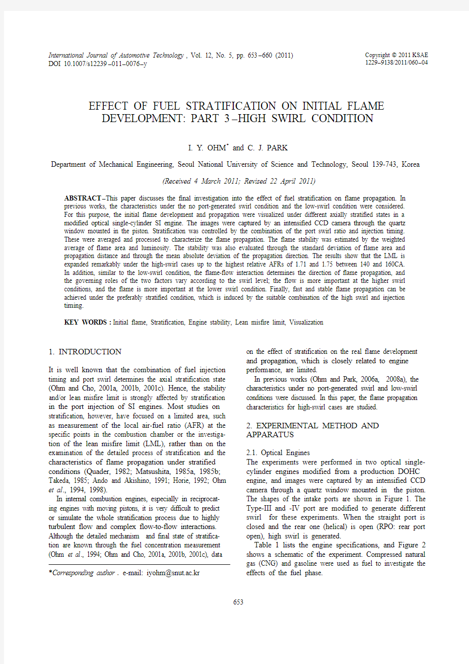
The experiments were performed in two optical single-cylinder engines modified from a production DOHC engine, and images were captured by an intensified CCD camera through a quartz window mounted in the piston.The shapes of the intake ports are shown in Figure 1. The Type-III and -IV port are modified to generate different swirl for these experiments. When the straight port is closed and the rear one (helical) is open (RPO: rear port open), high swirl is generated.
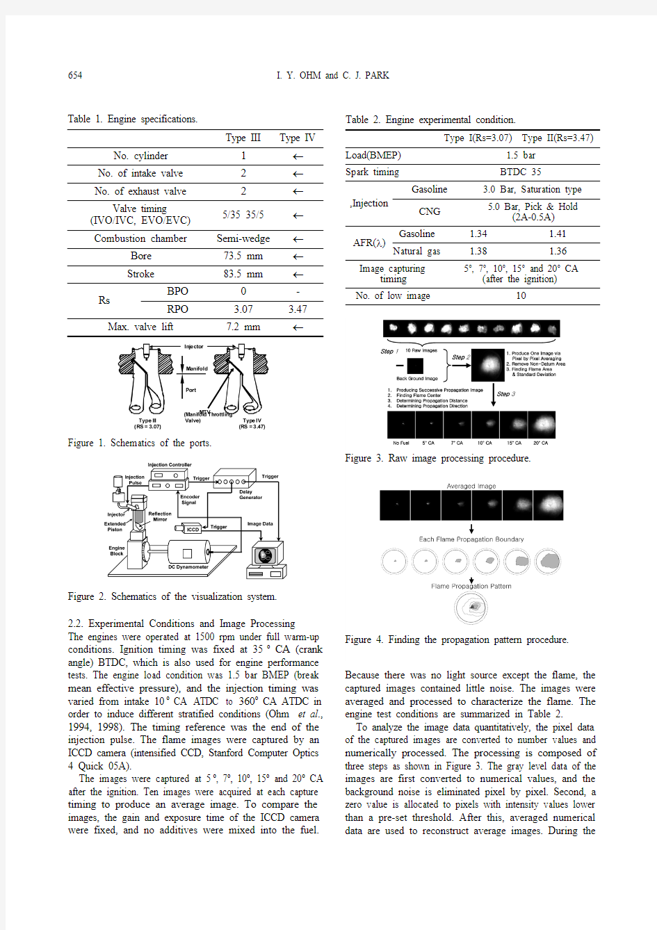
Table 1 lists the engine specifications, and Figure 2shows a schematic of the experiment. Compressed natural gas (CNG) and gasoline were used as fuel to investigate the effects of the fuel phase.
*Corresponding author . e-mail: iyohm@snut.ac.kr
654I. Y. OHM and C. J. PARK
2.2. Experimental Conditions and Image Processing
The engines were operated at 1500 rpm under full warm-up conditions. Ignition timing was fixed at 35o CA (crank angle) BTDC, which is also used for engine performance tests. The engine load condition was 1.5 bar BMEP (break mean effective pressure), and the injection timing was varied from intake 10o CA ATDC to 360o CA ATDC in order to induce different stratified conditions (Ohm et al .,1994, 1998). The timing reference was the end of the injection pulse. The flame images were captured by an ICCD camera (intensified CCD, Stanford Computer Optics 4 Quick 05A).
The images were captured at 5o , 7o , 10o , 15o and 20o CA after the ignition. Ten images were acquired at each capture timing to produce an average image. To compare the images, the gain and exposure time of the ICCD camera were fixed, and no additives were mixed into the fuel.
Because there was no light source except the flame, the captured images contained little noise. The images were averaged and processed to characterize the flame. The engine test conditions are summarized in Table 2.
To analyze the image data quantitatively, the pixel data of the captured images are converted to number values and numerically processed. The processing is composed of three steps as shown in Figure 3. The gray level data of the images are first converted to numerical values, and the background noise is eliminated pixel by pixel. Second, a zero value is allocated to pixels with intensity values lower than a pre-set threshold. After this, averaged numerical
data are used to reconstruct average images. During the
Figure 1. Schematics of the ports.
Figure 2. Schematics of the visualization system.Table 1. Engine specifications.
Type III
Type IV No. cylinder 1←No. of intake valve 2←No. of exhaust valve 2←Valve timing (IVO/IVC, EVO/EVC)5/35 35/5←Combustion chamber
Semi-wedge ←Bore 73.5 mm ←Stroke 83.5 mm
←Rs
BPO 0-RPO
3.07 3.47Max. valve lift
7.2 mm
←
Table 2. Engine experimental condition.
Type I(Rs=3.07)Type II(Rs=3.47)
Load(BMEP) 1.5 bar Spark timing
BTDC 35
,Injection
Gasoline
3.0 Bar, Saturation type CNG 5.0 Bar, Pick & Hold
(2A-0.5A)
AFR(λ)
Gasoline 1.34 1.41Natural gas
1.38
1.36
Image capturing
timing 5o , 7o , 10o , 15o and 20o CA
(after the ignition)
No. of low image
10
Figure 3. Raw image processing procedure.
Figure 4. Finding the propagation pattern procedure.
EFFECT OF FUEL STRATIFICATION ON INITIAL FLAME DEVELOPMENT: PART 3-HIGH SWIRL CONDITION 655
averaging, the weighted flame area, in which the intensity of the pixel is considered, and the standard deviation of this area are calculated. Finally, all the averaged images under the same injection timing are integrated into one image, in which the images are successively arranged as a sequence of the crank angle. In addition, the flame center and the distance of the center from the ignition point and its standard deviation are estimated. The propagation direction is another important parameter of the flame characteristics;the mean direction and the mean average deviation (MAD)were estimated by simply averaging the data. In addition,the boundary of flame propagation was determined by observing the propagation patterns, as shown in Figure 4.In this figure, dotted circle lines indicate the real cylinder bore, and solid lines indicate the visualizing window boundary. The detailed processing method is specified in the previous work.
3. RESULTS AND DISCUSSION
3.1. Engine LML
Figure 5 shows the lean misfire limit (LML) of both of the engines as a function of the injection timing under the high-swirl condition (Ohm and Park, 2002). Similar to the no-swirl and low-swirl conditions (Ohm and Park, 2006a, 2008a), the intake stroke injection significantly affects the LML;however, for high-swirl cases, the LML is expanded remarkably. The LML increases up to the highest relative AFR of 1.71 and 1.75 at around 140o -160o CA. A bimodal phenomenon, which was observed for the low-swirl ports (Ohm and Park, 2008a), is not apparent under the high swirl.As shown in Figure 5(c), the LML envelopes for both the gasoline and the gaseous fuel (CNG) are similar. The main difference is that the LML envelopes for CNG fuel are retarded by about 30o - 60o CA. The CNG fuel arrives at the valve faster than gasoline. The difference in the injection timing between gasoline and CNG disappears when this is considered.
3.2. Raw Flame Image
Figures 6 and 7 show the averaged flame images of gasoline and CNG fuel according to injection timings. In the figures, the angles on the right side are the injection timings, and the angles on the bottom correspond to the crank angle after ignition.
The figures indicate that the initial flame development coincides strongly with the LML from the injection timing point of view: for high LML timing (140o -160o CA ATDC in gasoline and 130o -200o CA in CNG), clear and strong flames are observed. However, visible flames are hardly observed in other injection timings. There was essentially no observable difference between gasoline and CNG flame
propagation.
Figure 5. LML as a function of injection timing: (a) Type-I II (RPO, RS =3.07); (b) Type-IV (RPO, RS=3.47); (c)
CNG fueling.
Figure 6. Flame propagation image as a function of injection timing when Rs = 3 .07.
656I. Y. OHM and C. J. PARK
The quantitative data provide a detailed examination of the propagating characteristics.
3.3. Flame Propagation Pattern and Direction
Figures 8~11 illustrate the propagation boundaries of the gasoline and CNG flames. The thick white lines in each pattern show the moving passage of the flame centers; the position and intensity are used concurrently to determine
this value. Comparing these figures to simple averaged images, it can be seen that the flames are more clearly visible as a result of finding the boundary.
As mentioned above, the intensity of the flame is not considered in defining the boundary, and therefore, the larger area does not necessarily mean a stronger flame.
Nevertheless, stronger flames were observed to have larger propagation boundaries overall. In the figure, the upper
part of image is the exhaust side and the lower part the intake side.
In previous works (Ohm and Park, 2006a, 2008a), the
main propagation direction was toward the exhaust (upper)side due to the bulk air motion. The main direction,however, inclines highly to the right side under the high-swirl conditions. Each image shows a similar trend of flame propagation regardless of injection timing and fuel.To further understand the propagation characteristics, the flame center directions were calculated under the various
bases. These results are shown in Figures 12 and 13.The plot shows the overall average (longest line)estimated from all raw images, with values of 1050 for gasoline and 1350 for CNG . Averages on the base of the crank angle after ignition and the fuel injection timing (shortest line) were also calculated. The crank angles in the figure indicate the injection timings.
The information on flame propagation direction provides insight on several interesting phenomena.
As shown in the figures, the overall directions are 25o (gasoline), -3o (CNG , Rs=3.07) and 27o (CNG , Rs=3.47). In previous works (Ohm and Park, 2006a, 2008a), the directions were 99o (gasoline) and 103o (CNG) with no swirl. Other directions measured in this study were 105o (gasoline, Rs =1.99), 113o (CNG , Rs=1.99), 91o (gasoline,Rs =2.79) and 85o (CNG , Rs=2.79). Therefore, the directions of flame propagation in these cases are quite different from those of the no-/low-swirl cases. In addition,the difference in direction as a function of the swirl ratio is remarkable. In the no-/low-swirl case, the maximum difference in direction was 28o when the swirl ratio increased by 0.80 from 1.99 to 2.79 in the CNG fueling.However, when the swirl ratio is increased by only 0.28from 2.79 to 3.07, the difference in direction is 66o for gasoline and 88o for CNG . The change in direction with
Figure 7. Flame propagation image as a function of injection timing when Rs=3.47.
Figure 8. Flame propagation boundary (gasoline, Rs=3.07).
Figure 9. Flame propagation boundary (CNG , Rs=3.07).
Figure 10. Flame propagation boundary (Gasoline, Rs=3.47).
Figure 11. Flame propagation boundary (CNG , Rs=3.47).
EFFECT OF FUEL STRATIFICATION ON INITIAL FLAME DEVELOPMENT: PART 3-HIGH SWIRL CONDITION 657
CNG is especially peculiar because it is a much bigger change than that observed with the other fuels.
These propagation characteristics, which differ from the no-/low-swirl condition, might be explained as follows.The in-cylinder flow of the normal 4-valve SI engine is fundamentally a function of swirl and tumble (inclined swirl) if one port is deactivated due to the non-zero valve angle and the eccentricity of the valve position with the cylinder center (Ohm, I. Y . and Park, C. J. 2008b, 2009).However, when 2 intake ports are used, the dominant motion is tumble (Ohm and Park, 2006b, 2006c).
Therefore, under a no-swirl condition, the main propaga-tion direction is towards the exhaust side due to the bulk tumbling motion (Ohm and Park, 2006a). In addition, in the low-swirl condition, the early stage flames propagate to the left of the overall direction, but the later flames turn incrementally to the right as they grow due to the flame-flow interaction. The roles of two governing factors (flow and mixture distribution) that determine the propagation are summarized in Figure 14 (Ohm and Park, 2008a).
The effect of these two governing factors on the propagation direction under the high-swirl condition was considered in a similar way to their effect for the low-swirl cases. Considering that the flames propagate to the right of the combustion chamber and that the directions coincide with the rotating swirl motion, the flow might play a more dominant role in determining the flame direction due to the higher flow rate in these cases.
There are, however, some differences in the details of the process as follows: shown in Figures 12 and 13 as direction 1, the early stage flame propagates after ignition to the left side of the overall direction, which shifts clockwise to the right side (the swirl rotation direction); as the flame grows,its direction shifts to the left, which is against the swirl motion. However, the flame direction changes from the right side to the left side of the overall direction consistently when Rs is 3.07 with the CNG fueling. These changes with respect to the overall direction are quite different from the
no-/low-swirl cases, in which flames rotate in the same
Figure 12. Direction of flame propagation (Rs=3.07).
Figure 13. Direction of flame propagation (Rs=3.47).Figure 14. Flame and flow interaction in the combustion
chamber under the high-swirl condition.
Figure 15. Flame and flow interaction in combustion chamber under high swirl condition.
658I. Y. OHM and C. J. PARK
direction as they grow.
These phenomena might be caused by the difference in the fuel distribution as compared to the low-swirl case. That is, at the early stage, the small flame moves under the great effect of the high swirling motion. Then, the influence of the concentration of the fuel in front of the flame surface becomes greater as the flame grows. Consequently, the flame speed on the fuel-rich side is relatively faster than that of the flame on the lean side. Therefore, it is supposed that the left side of the overall direction is the fuel-rich zone. This propagation is summarized in Figure 15.
The exceptional case (CNG, Rs=3.07) could not be analyzed properly with the existing data. More information about the in-cylinder flow and the fuel distribution is required. One possible cause is a disturbance of intake flow due to the high-pressure gaseous fuel injection. The high-pressure injection might reinforce the swirling motion and induce a different fuel distribution, which causes the CNG propagation pattern shown in Figure 12.
Some characteristics exist for high-swirl cases that are similar to the characteristics in the low-swirl case. For example, as the injection timings are varied, the deviations of the propagation from the overall direction are different for each fuel, and the deviations of the CNG flames are larger than those of the gasoline flames. In addition, the propagating directions tend clockwise in the low LML injection timings. The fuel stratification is assumed to be insufficient for the flames to propagate against the flow when the LML is low. Therefore, it might be said that the direction is governed by flow under the weak stratified condition.
In brief, the flame-flow interaction determines the direction of flame propagation, and the flow plays govern-ing roles under the high-swirl condition. Considering this result and the former works (Ohm and Park, 2006a, 2008a), it has been determined that the dominant factors vary according to the swirl level; the flow is more important at
the higher swirl conditions, and the flame is more important Figure 16. Flame area and deviation of gasoline fueling as a
function of injection timing; (a) weighted flame area; (b)
COV of weighted flame area; (c) COV of flame propagation
distance and (d) MAD of the propagation direction
(gasoline, Rs=3.07).
Figure 17. Flame area and deviation of gasoline fueling as a
function of injection timing; (a) weighted flame area; (b)
COV of weighted flame area; (c) COV of flame propagation
distance and (d) MAD of the propagation direction (CNG,
Rs=3.07).
Figure 18. Flame area and deviation of gasoline fueling as a
function of injection timing; (a) weighted flame area; (b)
COV of weighted flame area; (c) COV of flame propagation
distance and (d) MAD of the propagation direction
(gasoline, Rs=3.47).
Figure 19. Flame area and deviation o f gasoline fueling as a
function of injection timing; (a) weighted flame area; (b) COV
of weighted flame area; (c) COV of flame propagation
distance and (d) MAD of the propagation direction (CNG,
Rs=3.47).
EFFECT OF FUEL STRATIFICATION ON INITIAL FLAME DEVELOPMENT: PART 3-HIGH SWIRL CONDITION659
at the lower swirl conditions.
3.4. Variations in Area and Direction
Figures 16~19 represent the weighted flame area, COV of the flame area, COV of propagation distance and MAD of the propagation direction. Qualitatively, the characteristics of all these parameters coincide with the former works; at the higher LML region, the larger flame area, the lower COV of the flame area and the lower MAD of the direction are observed during the initial flame stage. All of these mean that more stable combustion is achieved in this region. Therefore, fast and stable flame propagation could be achieved under the preferably stratified condition, which is induced by the suitable combination of the high swirl and injection timing. These might also show the importance of the initial flame for the stability and LML (Heywood, 1988; Stone, 1992).
4. CONCLUSIONS
From the visualization of initial flame development in an optical single-cylinder engine under the high-swirl condition, the following observations have been made: (1)The LML is expanded remarkably under the high swirl
up to the highest relative AFR of 1.71 and 1.75 at around 140o - 160o CA.
(2)A bimodal LML phenomenon, which was observed for
the low-swirl ports, is not apparent under the high swirl condition.
(3)The direction of flame propagation is independent of
both injection timing and fuel type, given the same swirl ratio.
(4)The initial flame development coincides strongly with
the LML with respect to the injection timing. (5)The flame-flow interaction determines the direction of
flame propagation, and the governing roles of the two factors vary according to the swirl level; the flow is more important at the higher swirl conditions, and the flame is more important at the lower swirl conditions.
(6) At the higher LML region, the larger flame area, the
lower COV of the flame area and the lower MAD of the direction are observed.
(7)Fast and stable flame propagation could be achieved
under the preferably stratified condition, which is induced by the suitable combination of the high swirl and injection timing.
REFERENCES
Ando, H. and Akishino, K. (1991). Concept of lean combustion by barrel-stratification. SAE Paper No. 912207.
Heywood, J. B. (1988). Internal Combustion Engine Fundamentals. MacGraw-Hill. New York. 371?375. Horie, K. (1992). The Development of high fuel economy and high performance four-valve lean burn engine. SAE
Paper No. 920455.
Matsushita, S. (1985a). Development of the Toyota lean combustion system. SAE Paper No. 850044. Matsusita, S. (1985b). Effects of helical port with swirl control valve on the combustion and performance of SI engine. SAE Paper No. 850046.
Ohm, I. Y. and Cho, Y. S. (2001a). In-cylinder fuel behavior according to fuel injection timing and port characteristics in an SI engine: Part I-Without swirl. Trans. Korean Society of Automotive Engineers 9, 2, 19?27.
Ohm, I. Y. and Cho, Y. S. (2001b). In-cylinder fuel behavior according to fuel injection timing and port characteristics in an SI engine: Part II-With low/medium swirl. Trans. Korean Society of Automotive Engineers 9, 3, 9?17.
Ohm, I. Y. and Cho, Y. S. (2001c). In-cylinder fuel behavior according to fuel injection timing and port characteristics in an SI engine: Part III-With high swirl. Trans. Korean Society of Automotive Engineers 9, 3, 18?26.
Ohm, I. Y. and Park, C. J. (2002). Experimental study on axial stratification process and its effects (1). Int. J. Korea Society of Mechanical Engineers 16, 11, 1457?1469.
Ohm, I. Y. and Park, C. J. (2006a). Effect of fuel stratification on initial flame development: Part 1-Without swirl. Int. J. Automotive Technology 7, 5, 519?526.
Ohm, I. Y. and Park, C. J. (2006b). In-cylinder intake flow characteristics according to inlet valve angle. Trans. Korea Society of Automotive Engineers 14, 3, 142?149. Ohm, I. Y. and Park, C. J. (2006c). In-cylinder compression flow characteristics according to inlet valve angle. Trans. Korean Society of Automotive Engineers14, 4, 77?83.
Ohm, I. Y. and Park, C. J. (2008a). Effect of fuel stratification on initial flame development: Part II-Low swirl condition. Int. J. Automotive Technology 9, 6, 671?678.
Ohm, I. Y. and Park, C. J. (2008b). Effect of inlet valve angle on in-cylinder swirl generation characteristics (I). Trans. Korean Society of Automotive Engineers 16, 6, 148?156.
Ohm, I. Y. and Park, C. J. (2009). Effect of inlet valve angle on in-cylinder swirl generation characteristics (II). Trans. Korean Society of Automotive Engineers 17, 2, 42?48.
Ohm, I. Y., Ahn, H. S., Lee, W. J., Kim, W. T., Park, S. S. and Lee, D. U. (1994). Development of HMC axially stratified lean combustion engine. 1993 SAE Trans. 103, 3, 1298?1311.
Ohm, I. Y., Jeong, K. S. and Jeung, I. S. (1998). Effects of injection timing on the lean misfire limit in an SI engine. 1997 SAE Trans. 106, 3, 42?55.
Quader, A. A. (1982). The axially-stratified-charge engine.
660I. Y. OHM and C. J. PARK
SAE Paper No. 820131.
Stone, R. (1992). Introduction to Internal Combustion Engines. 2nd Edn. MacMillan. London. 72?74.Takeda, K. (1985). Toyota central injection (CI) system for lean combustion and high transient response. SAE Paper No. 851675.
目录 第一章编制说明 (2) 第一节编制目的: (2) 第二节编制依据: (2) 第三节本工程施工采用的主要标准: (3) 第二章工程概况及特点 (4) 第一节工程基本情况: (4) 第二节工程概况: (4) 第三节工程特点 (5) 第三章施工总体部署 (5) 第一节实施目标 (5) 第二节施工顺序 (6) 第三节施工准备计划 (6) 第四节施工组织管理 (10) 第四章工期和进度计划及进度保证措施 (14) 第一节工期目标 (15) 第二节施工进度计划安排 (15) 第三节施工进度计划控制 (15) 第四节施工进度计划保证措施 (16) 第五节强化施工进度计划管理和协调 (22) 第六节定期生产检查及生产会议 (23) 第七节生产资金的保证 (24) 第八节建立监督机制 (24) 第五章钢结构施工方案及工艺 (24) 第一节钢结构深化设计方案 (24) 第二节钢结构制作 (29) 第三节包装、运输、装卸及堆放 (37) 第四节主要构件制作工艺 (39) 第五节钢结构安装 (44)
第六章主要技术措施 (67) 第一节焊接质量控制 (67) 第二节吊装质量保证措施 (71) 第七章工程质量、质量保证措施及质保体系 (73) 第一节质量目标及质量计划 (73) 第二节项目部质量管理责任 (74) 第三节质量计划控制点设置 (76) 第四节施工过程质量控制 (78) 第五节抓分项工程的质量管理 (82) 第六节施工质量检验与评定 (84) 第七节最终交工检查验收 (87) 第八章施工安全和安全保证措施 (88) 第一节安全目标 (88) 第二节安全管理的意义 (88) 第三节安全管理的原则: (88) 第四节安全管理手段 (88) 第五节安全管理体系(见下图) (89) 第六节安全生产岗位责任制 (90) 第七节安全生产保证措施 (105) 第九章文明施工 (122) 第一节文明施工目标: (122) 第二节建立文明施工领导小组。 (123) 第三节文明施工管理措施 (123) 第四节场容场貌管理措施: (124) 第五节现场卫生管理措施: (125) 第六节现场队伍精神风貌及管理措施: (125)
1.柴油机特性曲线:用曲线形式表现的柴油机性能指标和工作参数随运转工况变化的规律。2.扫气过量空气系数:每一循环中通过扫气口的全部扫气量与进气状态下充满气缸工作容积的理论容气量之比 3.封缸运行:航行时船舶柴油机的一个或一个以上的气缸发生了一时无法排除的故障,所采取的停止有故障气缸运转的措施。 4.12小时功率:柴油机允许连续运行12小时的最大有效功率。 5.有效燃油消耗率:每一千瓦有效功率每小时所消耗的燃油数量。 6.示功图:是气缸内工质压力随气缸容积或曲轴转角变化的图形。 7.燃烧过量空气系数:对于1kg燃料,实际供给的空气量与理论空气需要量之比。 8.敲缸:柴油机在运行中产生有规律性的不正常异音或敲击声的现象。 9.1小时功率:柴油机允许连续运行1小时的最大有效功率。(是超负荷功率,为持续功率的110%。) 10.平均有效压力:柴油机单位气缸工作容积每循环所作的有效功。 11.热机:把热能转换成机械能的动力机械。 12.内燃机:两次能量转化(即第一次燃料的化学能转化成热能,第二次热能转化成机械能)过程在同一机械设备的内部完成的热机。 13.外燃机: 14.柴油机:以柴油或劣质燃料油为燃料,压缩发火的往复式内燃机。 15.上止点:活塞在气缸中运动的最上端位置,也是活塞离曲轴中心线最远的位置。下止点 16.行程:活塞从上止点移动到丅止点间的位移,等于曲轴曲柄半径R的两倍。 17.气缸工作容积:活塞在气缸中从上止点移动到丅止点时扫过的容积。 18.压缩比:气缸总容积与压缩室容积之比值,也称几何压缩比。 19.气阀定时:进排气阀在上.丅止点前启闭的时刻称为气阀定时,通常气阀定时用距相应止点的曲轴转角表示。 20.气阀重叠角:同一气缸在上止点前后进气阀与排气阀同时开启的曲轴转角。(进排气阀相通,依靠废气流动惯性,利用新鲜空气将燃烧室内废气扫出气缸) 21.扫气:二冲程柴油机进气和排气几乎重叠在丅止点前后120-150曲轴转角内同时进行,用新气驱赶废气的过程。 22.直流扫气:气流在缸内的流动方向是自下而上的直线运动。(空气从气缸下部扫气口,沿气缸中心线上行驱赶废气从气缸盖排气阀排出气缸) 23.弯流扫气:扫气空气由下而上,然后由上而下清扫废气。 24.横流扫气:进排气口位于气缸中心线两侧,空气从进气口一侧沿气缸中心线向上,然后再燃烧室部位回转到排气口的另一侧,再沿中心线向下,把废气从排气口清扫出气缸。 25.回流扫气:进排气口在气缸下部同一侧,排气口在进气口上方,进气流沿活塞顶面向对侧的缸壁流动并沿缸壁向上流动,到气缸盖转向下流动,把废气从排气口中清扫出气缸。 26.增压:提高气缸进气压力的方法,使进入气缸的空气密度增加,从而增加喷入气缸的燃油量,提高柴油机平均有效压力和功率。 27.指示指标:以气缸内工作循环示功图为基础确定的一些列指标。只考虑缸内燃烧不完全及传热等方面的热损失,不考虑各运动副件存在的摩擦损失,评定缸内工作循环的完善程度。 28.有效指标:以柴油机输出轴得到的有效功为基础,考虑热损失,也考虑机械损失,是评定柴油机工作性能的最终指标。 29.平均指示压力:一个工作循环中每单位气缸工作容积的指示功。 30.指示功率:柴油机气缸内的工质在单位时间所做的指示功。 31.有效功率:从柴油机曲轴飞轮端传出的功率。
OpenStack的架构详解 OpenStack既是一个社区,也是一个项目和一个开源软件,它提供了一个部署云的操作平台或工具集。其宗旨在于,帮助组织运行为虚拟计算或存储服务的云,为公有云、私有云,也为大云、小云提供可扩展的、灵活的云计算。 1. OpenStack是什么 OpenStack既是一个社区,也是一个项目和一个开源软件,它提供了一个部署云的操作平台或工具集。其宗旨在于,帮助组织运行为虚拟计算或存储服务的云,为公有云、私有云,也为大云、小云提供可扩展的、灵活的云计算。 OpenStack旗下包含了一组由社区维护的开源项目,他们分别是OpenStackCompute(Nova),OpenStackObjectStorage(Swift),以及OpenStackImageService(Glance)。 OpenStackCompute[1],为云组织的控制器,它提供一个工具来部署云,包括运行实例、管理网络以及控制用户和其他项目对云的访问(thecloudthroughusersandprojects)。它底层的开源项目名称是Nova,其提供的软件能控制IaaS云计算平台,类似于AmazonEC2和RackspaceCloudServers。实际上它定义的是,与运行在主机操作系统上潜在的虚拟化机制交互的驱动,暴露基于WebAPI的功能。 OpenStackObjectStorage[2],是一个可扩展的对象存储系统。对象存储支持多种应用,比如复制和存档数据,图像或视频服务,存储次级静态数据,开发数据存储整合的新应用,存储容量难以估计的数据,为Web应用创建基于云的弹性存储。 OpenStackImageService[1],是一个虚拟机镜像的存储、查询和检索系统,服务包括的RESTfulAPI允许用户通过HTTP请求查询VM镜像元数据,以及检索实际的镜像。VM镜像有四种配置方式:简单的文件系统,类似OpenStackObjectStorage的对象存储系统,直接用Amazon'sSimpleStorageSolution(S3)存储,用带有ObjectStore的S3间接访问S3。 三个项目的基本关系如下图1-1所示:
第一章船舶动力装置系统 现代船舶动力装置,按推进装置的形式,可分为5大类: (1)·柴油机推进动力装置;(2)·汽油机推进动力装置;(3)·燃气轮机推进动力装置;(4)·核动力推进动力装置;(5)·联合动力推进装置。 现代民用船舶中,所采用的动力装置系统绝大多数是柴油机动力装置,因此,本书主要介绍以柴油机为动力装置的船舶,图1-1为船舶柴油机动力装置系统燃油供应系统原理图。 图1-1 柴油机动力装置系统燃油供应系统原理图 柴油机燃油系统包括三大功能系统,分别是输送、日用和净化。 1)油输送系统 燃油输送系统是为了实现船上各燃油舱柜间驳运及注入排出而设计的,所以,系统应包括燃油舱柜、输送泵、通岸接头和相应的管子和阀件。通过管路的正确连接和阀件的正确设置,实现规格书所要求的注入、调拨和溢流等功能。 设计前,要认真阅读规格书和规范的有关章节,落实本系统所涉及的舱柜和设备所要求的输送功能。 设计时,应注意如下几个方面: a.规格书无特殊要求,注入管应直接注入至各储油舱,再通过输送泵送至各日用柜和沉淀柜,各种油类的注入总管应设有安全阀,泄油至溢流舱,泄油管配液流视察器; b.所有用泵注入的燃油舱柜都要有不小于注入管直径的溢流管,溢流至相应的溢流舱或储油舱,具体规定见各船级社规范,溢流管要配液流视察器; c.从日用柜至沉淀柜的溢流,在日用柜哪的管子上都要开透气孔以防止虹吸作用,两柜的连接管处要有液流视察器。 d.装在日用柜和沉淀壁上低于液面的阀,有的船级社规范对其材料有具体的规定,选阀时应予以注意。 e.一般情况下输送系统的介质,温度和压力都是较低的,所以系统的管材选用III级管即可。
OpenStack 部署运维方案
目录 1.OpenStack 简介 (3) 2.Openstack私有云平台概况 (4) 3.OpenStack 部署方案 (6) 4.OpenStack 各组件配置 (8) 5.OpenStack 底层依赖软件版本、配置以及性能调优 (14) 6.运维经验 (17)
本文介绍了基于OpenStack 开发的云计算管理平台,以及在开发、运营、维护过程中遇到的问题和经验分享。作为大型互联网公司,IT 基础架构需要支撑包括生产、开发、测试、管理等多方面的需要,而且需求和请求的变化几乎每天都存在,需要内部的IT 基础架构能够足够灵活和健壮来满足各部门和团队的实际需要。 1.OpenStack 简介 OpenStack 是一个开源的IaaS 实现,它由一些相互关联的子项目组成,主要包括计算、存储、网络。 OpenStack 兼容一部分AWS 接口,同时为了提供更强大的功能,也提供OpenStack 风格的接口(RESTFul API)。和其他开源IaaS 相比,架构上松耦合、高可扩展、分布式、纯Python 实现,以及友好活跃的社区使其大受欢迎。 OpenStack 的主要子项目有: ? Compute(Nova)提供计算虚拟化服务,是OpenStack 的核心,负责管理和创建虚拟机。它被设计成方便扩展,支持多种虚拟化技术,并且可以部署在标准硬件上。 ? Object Storage(Swift)提供对象存储服务,是一个分布式,可扩展,多副本的存储系统。? Block Storage(Cinder),提供块存储服务,为OpenStack 的虚拟机提供持久的块级存储设备。支持多种存储后端,包括Ceph,EMC 等。 ? Networking(Neutron)提供网络虚拟化服务,是一个可拔插,可扩展,API 驱动的服务。? Dashboard 提供了一个图形控制台服务,让用户方便地访问,使用和维护OpenStack 中的资源。
上海国际海事信息与文献网发布时间:2007-03-20 浏览:3123 【摘要】从船用柴油机的市场、产品、技术等方面介绍了柴油机的现状及发展动向。论述当前国外气缸直径160 mm以上,单机功率大于1000 kW的大功率低速、中速、高速柴油机的总体技术水平、技术发展概况,特别是在提高可靠性、改善其低工况特性、降低其排放和智能柴油机等方面进行阐述,并预测今后的发展趋势。 0 引言 柴油机因其功率范围大、效率高、能耗低、使用维修方便而优于蒸汽机、燃气轮机等,在民用船舶和中小型舰艇推进装置中确立了主导地位。船用柴油机的整体结构及其零部件结构不断改进,特别是电子技术、自动控制技术在柴油机上的应用,使其各项技术指标不断创新,市场上已有一批性能好、油耗低、功率范围大、废气排放符合法定标准、可靠性高的产品。 柴油机相对汽油机的最大优点在于高压缩比。这使最大功率、热效率提高,油耗降低;发动机坚固、耐用,寿命变长。但柴油机缺点在于比功率低于汽油机,对空气利用率低,摩擦损失大。 1 低速柴油机 低速柴油机由于性能优良、可靠性好、使用维护方便、能燃用劣质燃油等优点,已成为大型油船、大型干散货船、大型集装箱船的主要动力。最新型低速柴油机在许多方面趋于一致。即结构方面,采用非冷却式喷油器、可变喷油定时油泵、长尺寸连杆、液压驱动式排气门、单气门直流扫气、定压增压、高效涡轮增压器;性能方面,平均有效压力不断提高,增加活塞平均速度,改进零部件结构,增加强度,保持原有的低燃油消耗水平,使单缸功率不断增大,使用寿命延长。电子液压控制系统取代传统的机械式的凸轮驱动机构,简化柴油机设计,降低成本,优化运行控制。近年来,其爆发压力从8 MPa上升到16 MPa,燃油消耗率从208g/(kw·h)降至155g/(kw·h)左右。 目前世界船用低速柴油机市场仍被MAN B&W、Wartsila-New Sulzer和日本三菱重工三大公司垄断,以生产总功率来说,分别约占57%、33%和10%。 MAN B&W公司通过提高气缸平均有效压力和活塞平均速度来提高单缸功率。为使MC系列柴油机的NOx排放量降低,采用提高压缩比和可导致平稳燃烧的喷射系统等措施。 为了在减少NOx排放时不影响燃油消耗率,在设计时应考虑采用增加喷射压力、压缩比、燃烧压力、增压器效率等措施。MAN B&W 6L60MC型柴油机是世界上第一台正式投入使用的“智能化”主机,其燃油喷射和排气阀控制均通过电子计算机完成,达到了低油耗、NOx低排放的目标。 Wartsila-New Sulzer公司通过重组后,在开发、设计和制造能力方面骤然大增。RTA系列低速柴油机为该公司20世纪80年代开发,至今近20年来该公司通过提高平均有效压力、增加活塞平均速度,探索达到更大功率的可能性。 通过增大行程/缸径比,探索提高推进效率的方法;通过提高最大燃烧压力和可变燃油正
康明斯柴油机简介 柴油机选用康明斯柴油发动机 康明斯公司成立于1919年,康明斯发动机是美国著名的三大品 牌(卡特比勒,康明斯,底特律)发动机之 一,自八十年代初进入中国以来,经过近二 十年的发展,已成为中国市场占有率最高的 进口发动机品牌,在中国客户当中具有较高 的知名度。在美国及美洲,卡特比勒以工程 机械著名,而康明斯则在车用和民用方面占 优势。 康明斯公司现已成为全球50匹马力以上 柴油机最大的生产厂家。康明斯公司在全世 界具有完善的销售和服务网络,在中国的重 庆和十堰设有合资制造厂。康明斯公司自92 年与江苏 星光发电设备有限公司合作,在发电机组市 场上取得了令人瞩目的成就。 康明斯柴油发电机组的基本特征: 技术先进,性能稳定可靠,工作寿命长 电子调速,独特的低压PT燃油喷射技术, 大大降低燃油系统故障率 遍布全国的专业服务网络,操作使用技术渐为中国可户所熟悉 油耗较低,运行成本低,功率范围由30KW-2200KW,产品规格齐全 发电机低电抗设计是非线性负载下的波形失真极小,并有良好的电动机启动能力。 发电机激磁系统能使机组在承受任何瞬间加载时,频率波动迅速恢复。 结构特点:直流电启动、四冲程、水冷、自带风扇、闭式循环冷却、进气中冷、废气涡轮增压。缸体设计坚固耐用,振动小,噪声小,直列 6 缸四冲程,运转平稳,效率高:可替换湿式气缸套,寿命长,维修方便;两缸一盖,每缸 4 气门,进气充分,性能卓越;强制水冷,热辐射小。
★重负载耐久性; ★杰出的瞬态响应性; ★采用电子调速器; ★电控系统采用DC24V,配备有停油电磁阀 优越性:与国内同类产品相比具有体积小、重量轻、油耗低、功率高、工作可靠,配件供应及维修方便的优势。采用电子调速器,具有冷却水温过高、机油压力低及超速报警并自动停车等保护功能。 优化设计: > 凸轮轴:大直径凸轴轮设计,可承受更高的负荷,精确控制气门和喷油正时;感应淬硬使凸轮寿命更长;优化设计的凸轮型线,使气六落座速度减缓,冲击力减小,减少磨损和振动,提高了发动要的可靠性和耐久性。 > 连杆:模锻连杆,杆身油道为活塞提供压力润滑油;杆身优化设计降低了单位应力。 > 冷却系统:采用皮带传动离心水泵。大流量水道为环绕气缸套、气门和喷油器的水腔提供均量的冷却水。旋转式水滤器含专用的干式化学添加剂 DCA4,可有效地防止气缸套穴蚀、水泵叶轮汽蚀及冷却系统零部件腐蚀、积垢等,控制冷却液的酸度,并去除杂质。 > 曲轴:高强度锻钢制造的整体式曲轴,采用高强化和高平衡精度工艺制造,曲轴圆角和轴颈采用先进的感应淬火处理技术,曲轴的疲劳强度更高。 > 气缸体:高强度合金铸铁制造,新型的缸体结构,使发动机刚性更好,密封性提高,振动减小,噪声降低。 > 气缸盖:每缸四气门设计,优化了空气/燃油的混合,改善燃烧和排放,发动机响应迅速,采用脉冲排气道,有利于废气能量的充分利用。高强度合金铸铁铸造,可以承受更高的冲击力,使发动机的超速能力更强,每两缸一个缸盖,维修、更换方便。 > 气缸套:可更换的湿式气缸套,比干式气缸套散热效果更好,更换容易而不需重镗气缸。
OpenStack Ocata版本单点部署 姓名: 日期:
目录 1 OpenStack安装环境搭建....................................... 错误!未定义书签。 CenOS 7初始配置 .................................................................. 错误!未定义书签。 基础环境配置 .......................................................................... 错误!未定义书签。 2 Keystone—认证服务 .............................................. 错误!未定义书签。 概述 .......................................................................................... 错误!未定义书签。 keystone安装与配置............................................................... 错误!未定义书签。 创建域/项目/用户/角色........................................................... 错误!未定义书签。 keystone功能验证................................................................... 错误!未定义书签。 创建客户端认证脚本 .............................................................. 错误!未定义书签。 3 Glance—镜像服务 .................................................. 错误!未定义书签。 概述 .......................................................................................... 错误!未定义书签。 glance安装与配置................................................................... 错误!未定义书签。 glance功能验证....................................................................... 错误!未定义书签。 4 Nova—计算服务..................................................... 错误!未定义书签。 概述 .......................................................................................... 错误!未定义书签。 controller节点安装与配置 ..................................................... 错误!未定义书签。 compute节点安装与配置 ....................................................... 错误!未定义书签。 nova功能验证 ......................................................................... 错误!未定义书签。 5 Neutron—网络服务 ................................................ 错误!未定义书签。 概述 .......................................................................................... 错误!未定义书签。 controller节点安装与配置 ..................................................... 错误!未定义书签。 neutron功能验证..................................................................... 错误!未定义书签。 6 Horizon—前台界面 ................................................ 错误!未定义书签。 概述 .......................................................................................... 错误!未定义书签。
第五章柴油机系统 第一节燃油系统 一、作用和组成 燃油系统是柴油机重要的动力系统之一,其作用是把符合使用要求的燃油畅通无阻地输送到喷油泵入口端。该系统通常由五个基本环节组成:加装和测量、贮存、驳运、净化处理、供给。 燃油的加装是通过船上甲板两舷装设的燃油注入法兰接头进行的。这样,从两舷均可将轻、重燃油直接注入油舱。注入管应有防止超压设施。如安全阀作为防止超压设备,则该阀的溢油应排至溢油舱或其他安全处所。注入接头必须高出甲板平面,并加盖板密封,以防风浪天甲板上浪时海水灌入油舱。燃油的测量可以通过各燃油舱柜的测量孔进行,若燃油舱柜装有测深仪表的话,也可以通过测深仪表,然后对照舱容表进行。 加装的燃油贮存在燃油舱柜中。对于重油舱,一般还装设加热盘管,以加热重油,保持其流动性,便于驳油。 燃油系统中还装设有调驳阀箱和驳运泵,用于各油舱柜间驳油。 从油舱柜中驳出的燃油在进机使用前必须经过净化系统净化。燃油净化系统包括燃油的加热、沉淀、过滤和离心分离。图5-1示出了目前大多数船舶使用的重质燃油净化系统。 图5-1 重质燃油净化系统 1-调驳阀箱;2-沉淀油柜燃油进口;3-高位报警;3-低位报警;4-温度传感器;5-沉淀油柜;6、16-水位传感器;7-供油泵; 8-滤器;9-气动恒压阀;9’-流量调节器;10-温度控制器;11、12-分油机;13-连接管;14-日用柜溢油管;15-日用油柜从图可以看出,通过调驳阀箱1,燃油被驳运泵从油舱送入沉淀油柜5,每次补油量限制在液位传感器3与3之间,自动调节蒸汽流量的加温系统加速油的沉淀分离并且可使沉淀油柜提供给供油泵7的油温变化幅度很小。供油泵后设气动恒压阀9和流量控制阀9’,以确保平稳地向分油机输送燃油,有利于提高净化质量。燃油进入分油机前,通过分油机加热器加温,加热温度由温度控制器10控制,使进入分油机的燃油温度几乎保持恒定。系统设有既能与主分油机串联也能并联的备用分油机,还设有备用供油泵,提高了系统的可靠性。分油机所分的净油进入日用油柜15,日用油柜设溢流管。在船舶正常航行的情况下,分油机的分油量将比柴油机的消耗量大一些,故在吸入口接近日用油柜低部设有溢流管,可使日用油柜低部温度较低、杂质和水含量较多的燃油引回沉淀柜,既实现循环分离提高分离效果,又使分油机起停次数减少,延长分油机使用寿命。沉淀柜和日用柜都设有水位传感器6、16,以提醒及时放残。 燃油经净化后,便可通过燃油供给系统送给船舶柴油机。近年来由于高粘度劣质燃油的
######################################安装service之前##################### 1.安装openstack-selinux和SQL数据库 RHEL and CentOS enable SELinux by default. Install the openstack-selinux package toautomatically manage security policies for OpenStack services: yum install openstack-selinux yum install mariadb mariadb-server MySQL-python 2.配置mariadb:Create and edit the /etc/my.cnf.d/mariadb_openstack.cnf file [mysqld] bind-address = 192.168.142.13 [mysqld] default-storage-engine = innodb innodb_file_per_table collation-server = utf8_general_ci init-connect = 'SET NAMES utf8' character-set-server = utf8 3.重启服务 systemctl enable mariadb.service systemctl start mariadb.service 4.加强mariadb数据库安全,这是root账户密码 mysql_secure_installation 5.安装信息队列
OpenStack部署与管理之 Fuel介绍 成胜 汉柏科技有限公司
内容 Fuel简介 Fuel架构 Fuel功能 Fuel扩展 2
OpenStack部署 OpenStack发展很猛,很多朋友都很认同,为了解决OpenStack部署的问题,让安装,配置变得更加简单易用,很多公司都投入人力去做这个。说到部署,肯定和OS有关,对于OpenStack来说,无非就是Ubuntu还是CentOS,当然也会和OpenStack版本有关。 其实部署工具,最麻烦的地方,不是软件的配置和安装,而是网络。用户的网络情况太多,还有OpenStack本身的网络也很复杂。
部署工具: RDO: REDHAT出品,支持Redhat、CentOS等系统。RDO基于puppet部署各个组件,支持单节点或多节点部署,在Redhat系操作系统上使用非常方便。 devstack: 这个应该是最老的Fuel简介了,可以用来快速部署一个OpenStack测试环境,基于git最新代码部署服务,并将所有服务都起在screen中,不适合生产环境直接使用。 Fuel: Mirantis出品,支持在ubuntu和centos上通过web界面配置并部署OpenStack,应该是目前最为直观的Fuel简介。支持自动发现部署节点,并部署 OpenStackHA,对OpenStack作健康检查等。
Mirantis 一家很牛逼的OpenStack服务集成商,他是社区贡献排名前5名中唯一一个靠软件和服务吃饭的公司(其他分别是Red Hat, HP, IBM, Rackspace)。相对于其他几个社区发行版,Fuel的版本节奏很快,平均每两个月就能提供一个相对稳定的社区版。
Openstack 云平台配置文档 一基本系统安装 1.Controller: a)硬件: i.CPU: 4核Intel(R) Core(TM) i5 CPU 750 @ 2.67GHz ii.内存:4G iii.硬盘:500G b)系统: Ubuntu11.04 Server 2.Node: a)硬件: i.CPU: 4核Intel(R) Core(TM) i5 CPU 750 @ 2.67GHz ii.内存:4G iii.硬盘:500G b)系统: Ubuntu11.04 Server 二安装Openstack Nova 1.配置网络: a)Controller: i. b)Node: i. 2.配置网桥 a)Controller:
i. ii.重启网络b)Node: i. ii.重启网络
3.NTP同步 a)sudo ntpdate https://www.doczj.com/doc/eb5359541.html, 4.安装配置数据库(Controller) a)OpenStack Nova 需要数据库的支持,这里选用MySQL i.Sudo apt-get install mysql-server b)修改MySQL绑定地址,以便其他的节点服务器也能访问这个数据库: i.Sudo vi /etc/mysql/my.conf ii.#bind-address=127.0.0.1 -> bing-address =0.0.0.0 iii.Sudo /etc/init.d/mysql restart c)创建一个名为nova的数据库,并设置root从任何IP访问的权限和密码: i.Sudo mysql –uroot –pfdse –e ‘CREATE DATABASE nova;’ ii.Sudo mysql –uroot –pfdse –e “GRANT ALL PRIVILEGES ON *.* TO ‘root’@’%’WITH GRANT OPTION;” iii.Sudo mysql –uroot –pfdse –e “SET PASSWORD FOR ‘root’@’%’= PASSWORD(‘fdse’);” 5.安装Glance镜像服务(Controller) a)Sudo apt-get install glance 6.安装OpenStack Nova a)Controller: i.Sudo apt-get install rabbitmq-server nova-common nova-doc python-nova nova-api nova-network nova-volume nova-objectstore nova-scheduler nova-compute ii.Sudo apt-get install –y euca2ools iii.Sudo apt-get install –y unzip b)Node i.Sudo apt-get install –y nova-compute nova-volume python-nova nova-common vlan ii.Sudo apt-get install –y unzip iii.Sudo apt-get install –y euca2ools
OpenStack newton部署一、环境 共需要2台主机 192.168.100.181 controller为控制节点和计算节点 192.168.100.182 compute1为计算节点 安装centos7.2 关闭防火墙(控制节点和计算节点都做) 关闭selinux /etc/sysconfig/selinux SELINUX=disabled setenforce 0 关闭iptables systemctl start firewalld.service systemctl stop firewalld.service systemctl disable firewalld.service 下面的表格给出了需要密码的服务列表以及它们的关系:
1.控制节点服务器 控制节点共配置2块网卡 eth1:192.168.100.181 eth2:不设置ip为trunk模式 添加/etc/hosts 设置NTP服务 # yum install chrony 编辑/etc/chrony.conf allow192.168.100.0/24 允许192.168.100.0网段访问 启动NTP服务 # systemctl enable chronyd.service # systemctl start chronyd.service # timedatectl set-timezone Asia/Shanghai 设置时区# timedatectl status 查看时区
安装openstack源及软件包 yum install centos-release-openstack-newton yum upgrade yum install python-openstackclient yum install openstack-selinux yum install mariadbmariadb-server python2-PyMySQL yum install rabbitmq-server yum install memcached python-memcached yum install openstack-keystone httpdmod_wsgi yum install openstack-glance yum install openstack-nova-apiopenstack-nova-conductor openstack-nova-console openstack-nova-novncproxyopenstack-nova-scheduler yum install openstack-nova-compute yum install openstack-neutron openstack-neutron-ml2 openstack-neutron-linuxbridgeebtablesipset yum install openstack-dashboard 开启nova用户的登录权限. usermod -s /bin/bash nova 生成秘钥(各个计算节点执行) 控制节点也需要互信 su– nova /usr/bin/ssh-keygen -t rsa /usr/bin/ssh-keygen -t dsa 所有计算节点均配置 cat<< EOF > ~/.ssh/config Host * StrictHostKeyChecking no UserKnownHostsFile=/dev/null EOF 分发ssh到各个计算节点 computer1 scp id_dsa.pub 192.168.100.181:/var/lib/nova/.ssh/id_dsa.pub3 scp id_rsa.pub 192.168.100.181:/var/lib/nova/.ssh/id_rsa.pub3 controller(192.168.100.181): cat id_dsa.pub id_dsa.pub2 id_rsa.pub id_rsa.pub2 id_rsa.pub3 id_dsa.pub3 >authorized_keys chmod 644 authorized_keys scpauthorized_keys computer1:/var/lib/nova/.ssh
Openstack安装部署手册 Havana版本
目录 1.环境 (4) 2.组件整体结构 (4) 3.环境准备 (5) 3.1. 网卡配置 (5) 3.2. 修改主机名 (5) 3.3. 安装mysql 数据库 (5) 4.安装openstack包 (6) 4.1. 安装openstack 单元包 (6) 4.2. 安装Messaging server (6) 5.安装keystone认证服务 (6) 5.1. 创建openstack keystone 与数据库的连接 (6) 5.2. 定义一个授权令牌 (6) 5.3. 配置创建密钥与证书 (7) 5.4. 启动keystone (7) 5.5. 定义用户租客和roles (7) 5.6. 创建服务与定义API endpoint (8) 6.配置glance (9) 6.1. 安装glance 组建 (9) 6.2. 创建glance数据连接 (9) 6.3. keystone下定义名为glance的用户 (9) 6.4. 添加glance roles (9) 6.5. 配置imgae的服务的身份验证 (9) 6.6. 添加凭证到/etc/glance/glance-api-paste.ini 和/etc/ (10) 6.7. glance/glance-registry-paste.inifiles.两个文件 (10) 6.8. keysotne创建glance 服务 (10) 6.9. 启动glance服务 (11) 6.10. 校验glance服务 (11) 7.安装nova 组建 (12) 7.1. 配置nova数据连接 (12) 7.2. keysotne创建nova user (12) 7.3. 添加roles (12) 7.4. 配置计算服务的身份验证 (13) 7.5. keysotne创建nova service (13) 7.6. 创建endpoint (13)
康明斯A2300发动机 1.A2300发动机是康明斯马力最小,结构最简单的一款发动机. 2.发动机序列号都是以7开头的数字.是四缸机械式发动机 3.主要适用于:小型挖掘机叉车。70010033发动机总成号 4.配件是以4900开头的数字.韩国进口居多. 5.凸轮轴衬套只有一道。(一台车只需要一件) 6.水泵一般有两款:一款是挖掘机的,一款是叉车的。 7.康明斯A B C 系列发动机都是单近单排的气门组 8.康明斯N K M系列发动机都是双近双排的气门组 9.机油滤清器:16034 柴油滤清器:1235 专用机油康明斯蓝至尊70506 10.两种燃油泵:①带增压器的燃油泵是通用②不带增压器的燃油泵是通用的. 11.整机有两款:①带增压器的②不带增压器的 12.配件名称因书面叫法和口语叫法或地区叫法会有所不同(曲轴瓦.主轴瓦.大瓦) 13.主轴瓦4缸机一套10片止推片是分体式的一套4片.修理包不分上下只有一套 14.叉车①大宇重工业烟台有限公司D203 D303系列 15.②卡斯(卡特)厦门D20E系列 16.③烟台大宇机械公司D303系列 17.④斗山机械D303系列 18.挖掘机①广西玉林玉柴工程机械有限公司35-7 45-6系列 19.②湖南山河智能机械有限公司65系列 20.③山东卡特重工机械公司W45 40-6 45-6系列 21.④山东众友工程机械有限公司40-1
康明斯B3.3发动机 1.发动机序列号都是以68开头的数字.是四缸机械式发动机 2.配件号以大多数以英文字母C开头+数字620开头的11序列组合 3.发动机号码68089226 4.6c8.3发动机号码46358303 5.挖掘机:小松(发动机名称为4D95)玉柴柳工山河智能南特临工卡特 临工力士德众友等 6.叉车:合肥(合叉)杭州(杭叉)大连叉车斗山等 7.装载机:徐工临工等 8.B3.3发动机的凸轮轴衬套一整套为3件,止推瓦(片)一整套为3片 康明斯发动机基本常识和配套厂家 康明斯发动机整车滤芯主要指定配套厂家美国()弗列加 弗列加滤芯英文字母的含义: —机油滤清器—柴油滤清器(也有配预滤器的)例如5327 —空气滤清器—空气滤清器总成—柴油油水分离器水滤器 注:机油滤清器也分:①复合滤和①直通滤芯②旁通滤芯 柴油滤清器也分:柴油滤芯和预滤器
OpenStack的架构 1.OpenStack是什么 OpenStack既是一个社区,也是一个项目和一个开源软件,它提供了一个部署云的操作平台或工具集。其宗旨在于,帮助组织运行为虚拟计算或存储服务的云,为公有云、私有云,也为大云、小云提供可扩展的、灵活的云计算。 OpenStack旗下包含了一组由社区维护的开源项目,他们分别是OpenStack Compute (Nova),OpenStack Object Storage(Swift),以及OpenStack Image Service(Glance)。 OpenStack Compute[1],为云组织的控制器,它提供一个工具来部署云,包括运行实例、管理网络以及控制用户和其他项目对云的访问(the cloud through users and projects)。它底层的开源项目名称是Nova,其提供的软件能控制IaaS云计算平台,类似于Amazon EC2和Rackspace Cloud Servers。实际上它定义的是,与运行在主机操作系统上潜在的虚拟化机制交互的驱动,暴露基于Web API的功能。 OpenStack Object Storage[2],是一个可扩展的对象存储系统。对象存储支持多种应用,比如复制和存档数据,图像或视频服务,存储次级静态数据,开发数据存储整合的新应用,存储容量难以估计的数据,为Web应用创建基于云的弹性存储。 OpenStack Image Service[1],是一个虚拟机镜像的存储、查询和检索系统,服务包括的RESTful API允许用户通过HTTP请求查询VM镜像元数据,以及检索实际的镜像。VM镜像有四种配置方式:简单的文件系统,类似OpenStack ObjectStorage的对象存储系统,直接用Amazon'sSimple Storage Solution (S3)存储,用带有Object Store的S3间接访问S3。 三个项目的基本关系如下图1-1所示: 2.云服务提供商的概念架构 OpenStack能帮我们建立自己的IaaS,提供类似Amazon Web Service的服务给客户。为实现这一点,我们需要提供几个高级特性: a)允许应用拥有者注册云服务,查看运用和计费情况; b)允许Developers/DevOps folks创建和存储他们应用的自定义镜像; c)允许他们启动、监控和终止实例; d)允许Cloud Operator配置和操作基础架构 这四点都直击提供IaaS的核心,现在假设你同意了这四个特性,现在就可以将它们放