非正交可重组机床的控制-外文翻译
- 格式:doc
- 大小:1.27 MB
- 文档页数:24
车削中恒定切削力的自组织模糊控制Received: 13 October 2004 / Accepted: 3 January 2005 / Published online: 17 August 2005 Springer-Verlag London Limited 2005摘要:在现代制造中,恒定力的控制逐渐成为一项重要技术。
特别是恒定切削力的控制,它是一种提高金属切削质量与车削工具寿命的有效方法。
但是,车削系统一般有非线性和不确定性的动态特征。
设计恒定切削力的模拟控制器是很困难的,因为一个准确的数学模型在车削系统中是很难建立的。
因此,这项研究利用了一个自由模型的模糊控制器控制车削系统以便得到恒定的切削力。
然而,设计传统的模糊控制器(TFC) 时,数据库与TFC固定后,其设计很难及时的进行调节并且根据系统做出相应的输出响应,取得理想的控制效果。
为了解决上述问题,这里建立了自组织模糊控制器(SOFC)为恒定切削力的控制系统。
SOFC在车削控制过程中不断更新,它从零初始的模糊控制表开始,克服了TFC设计时的困难,但是也要在车削控制系统中建立相应的支持模糊控制器模糊控制表,从而确定所提出的智能控制器的适应性,这项工作对旧的车床车削系统作了翻新改进从而达到恒定切削力的控制。
实验成果已经证实,SOFC比TFC在恒定切削力上有更好的控制能力。
关键词:恒定切削力控制、自组织模糊控制器、车削系统。
1.引言在生产力和降低劳动成本的需要下,数控机床(CNC)已广泛应用于工业生产,其加工的零件具有很高的精度和形状复杂性。
在数控系统中用数值控制器(NC)设计电脑程序时,要求快速准确的控制车削刀具,这给生产力带来很大提高:统一的零件加工,而且较少依赖经验知识和熟练的机械操作。
在加工过程中,数控程序员通常选择组合机床类型及主轴速度。
按常规,数控程序员保守的选定机床参数及主轴速度是为了防止任何对刀具物理性的破坏。
这样一来降低了加工效率。
概率(几率)probability·方差variance·分散维修decentralized maintenance·动态试验dynamic test·动力设备设施管理power facilities management·除尘、防护设备管理duct—proof and protective equipment managemen t ·抽样调查sampling investigation·备件国产化管理domestic production management of imported spare parts ·标准偏差standard deviation·安装预算budget of installation·包机制machine contracting system·班前检查与润滑制度regulation of check and lubrication before on shift ·[设备]交接班制度shift relief system·《设备管理条例》(《条例》)《Equipment Management Regulation》·[设备]修理repair·[设备]维修maintenance (and repair)·重点调查key-point investigation·重点设备管理management of key—point equipment·重点设备key—point equipment·责任事故liability accident·指数分布exponential distribution·直方图histogram·预付与托收承付prepayment and collection·预防性试验prophylactic test·预防为主prevention first·正交设计法(正交试验法)orthogonal design·正态分布normal distribution·运输车辆管理制度transportation vehicle management system·质量“三包” three guarantees of quality·质量事故accident due to quality·压力容器管理制度management regulation of pressure vessel·无故障运行时间mean time to failure·威布尔分布Weibull distribution·闲置设备管理制度idle equipment management·闲置设备idle plant·统计分析statistical analysis·维修性maintainability·维修信息管理maintenance information management·维护与计划检修相结合combination of service and planned maintenance ·随机事件random event·数控设备管理numerical control (NC)equipment management·三级保养制three-level service system·数学期望mathematical expectation·数学模型mathematical model·数理统计mathematical statistics·生产技术装备technical facilities in production·生产设备production equipment·寿命周期费用life cycle cost (LCC)·润滑油库管理制度mangement regulation of lubricant warehouse·商检(商品检验)commodity inspection·设计、制造与使用相结合combination of design, manufacturing and operation ·设备调研investigation on plant·设备的可靠性与可靠度reliability reliability theory·设备的节能性energy saving property of plant·设备的检查评比facility inspection and appraise through comparison for plant ·设备点检制度plant check system·设备的成套性complete set of plant·设备的安全性safety of plant·设备的生产率productivity of plant设备的耐用性durability of plant·设备的灵活性flexibility of plant·设备状态监测与诊断技术管理equipment condition monitoring and diagnostic technology manage·设备状态管理制度equipment condition management systen·设备综合管理total plant management·设备资产动态管理制度dynamic management system of plant assets·设备租赁plant leasing·设备修前准备制度preparation system before equipment repair·设备修理工时定额man—hours quota for equipment repair·设备修理费用定额expense quota for equipment repair·设备修理材料定额material quota for equipment repair·设备修理质量验收制度acceptance regulation of equipment repair quality·设备型号equipment model·设备型式type of equipment·设备经济寿命economical life of equipment·设备经营管理制度operation and business management system·设备技术档案technical document of plant·设备技术状况technical conditions of equipment·设备技术状态管理technical condition management of plant·设备技术资料管理制度management system for technical document and file of plant·设备技术性能technical properties of plant·设备技术寿命technical life of equipment·设备检修专业化协作specialized cooperation of plant maintenance·设备检修计划管理制度planning and management regulation of plant maintenance·设备检修计划plant maintenance plan·设备检修规程plant maintenance specification·设备检修质量plant maintenance quality·设备基础设计与施工design and construction of equipment foundation·设备合同管理management of equipment order contract·设备规划可行性分析feasibility studies of plant project设备规划investment plan of plant·设备功能(效能)performance of plant·设备工作能力operational capability of plant·设备管理考核制度examination and check systems of plant management·设备管理经济责任制度economic responsibility regulation of plant management ·设备管理岗位标准post standard of plant management·设备管理制度plant management systems·设备管理停歇时间定额(停歇天数)downtime quota for equipment repair·设备管理现代化plant engineering modernization·设备管理plant management,plant enginerring·设备固定资产管理制度fixed plant assets management systems·设备故障equipment failure·设备更新管理制度plant renewal management·设备更新plant renewal·设备更换plant replacement·设备岗位责任post responsibility of plant management·设备改造管理制度equipment modification management system·设备改造plant reconstruction,plant modernization·设备分级管理classified management of plant·设备定人定机、凭证操作规定operation regulation with fixed qualified operator and fixed eq·设备操作的“五项纪律” “five disciplines”of plant operation·设备操作规程operation specification of equipment·设备备品配件管理制度management regulation of equipment spare parts·设备备件库房管理制度management regulation of equipment spare parts inventory·设备报价to quote plant price·设备报废discard of plant·设备安装管理equipment installation management·设备安装equipment installation·设备巡回检查制度tours system to inspect plant·设备询价to enquire plant price设备选型plant model selection·设备验收交接制度acceptance check and reception systems of plant·设备统计报表制度statistic-reporting system of plant·设备维修技术资料technical document and date for plant maintenance·设备维修技术管理制度management regulation of plant maintenance technology ·设备维修定额equipment maintenance quota·设备维护规程equipment service specification·设备台帐unit account of plant·设备完好标准equipment perfectness norm·设备完好plant in good condition·设备索赔claims for equipment·设备使用规程specifications of usage·设备使用初期信息反馈管理information feedback management in initial operation period of pl·设备使用与维护管理制度management regulation for operation and service of equipment·设备全过程管理life—cycle management of plant·设备寿命life of equipment·设备润滑管理制度lubrication management regulation of plant·设备润滑“五定” “five fixation” of lubrication·设备事故管理制度accident management regulation of plant·设备事故“三不放过” three do not let pass of plant accident·设备事故plant accident·设备区域维修负责制region responsibility system of plant maintenance·设备前期管理和后期管理fore period and later period management of plant·设备前期管理规定regulation of fore period management of plant·设备磨损补偿wear compensation for plant·设备老化plant ageing·算术平均值(均值)arithmetic mean·强制保养制coercionary service system·投资效果系数effect coefficient of investment·设备经济管理制度economic management system of plant设备管理评优活动excellence selection activity in plant management·排列图(帕累托图)Pareto chart·负荷试验load test·故障停机时间breakdown time·工艺适应性technological adaptability·工程设备监理supervision of engineering facilities·工序控制点设备管理management of proccess—control—point equipment·合同变更与解除contract change and cancellation·混合维修combined maintenance·回归分析regression analysis·检查间隔期interval between inspections·检修社会化socialization of maintenance·集中维修centralized maintenance·技术先进性technical advancement·技术管理与经济管理相结合combination of technical management and economic management·计算机辅助设备管理computer—aided plant management·计划预修制度(ЛЛP)planned preventive maintenance system·进口设备离岸价FOB of imported equipment·进口设备管理imported equipment management·进口设备到岸价CIF of imported equipment·精、大、稀设备precise,large scale,rare plant·精、大、稀设备管理management of precise,large scale,rare equipment·精、大、稀、关键设备的“五定” “five fixed” of precise,large scale,rare,critical equipme·经济性economy·静态试验static test·开箱检查open—case inspection·平均偏差average deviation·平均等待时间mean waiting time,MWT·修理周期repair cycle·修理周期结构structure of repair cycle修理、改造与更新相结合combination of repair, modernization and renewal·修理复杂系数complexity coefficient of repair·修理间隔期time between repairs·租赁设备管理制度leased equipment management system·资金的时间价值time value of fund·自然事故natural accident·自制设备self-made equipment·自制设备管理制度management system for selfmade equipment·自制备件管理制度self—made spare parts management system·专业管理与群众管理相结合combination of professional management and mass management·转让设备(设备调剂)transfer of facility·典型调查typical investigation·地区(部门)修理中心areal (departmental)repair center·废油回收率recovery ratio of used oil·动力设备完好率perfectness ratio of power plant·定期保养完成率fulfillment ratio of periodic service·大修理平均停歇天数mean downtime(days)due to overhaul·重点设备完好率perfectness ratio of key—point equipments·一次交验合格率qualification ratio under first acceptance check·在用设备可利用率availability of plant in use·已安装设备利用率utilization ratio of installed equipments·万元固定资产年创利润率annual profit ratio per 10000 yuan fixed assets·万元产值占用维修费用maintenance expense for 1000 yuan production value ·实有设备安装率installation ratio of owned equipments·设备综合利用率comprehensive utilization ratio of plant·设备资产增值率added value rate of plant assets·设备资产投资回收期capital investment recovery period of plant·设备新度newness degree of plant·设备净资产创利润率profit ratio vs net book value of plant·设备计划台时利用率utilization ratio of planned time of plant设备构成比constitution ratio of plant·设备负荷率load rate of plant·设备返修率back repair rate·设备制度台时利用率utilization ratio of institutional time of plant·设备闲置率idelness ratio of plant·设备投资回收报率plant capital investment recovery ratio·设备投资产出比capital investment recovery period of plant·设备完好率perfectness ratio of plant·设备日常保养完成率plant daily service fulfillment ratio·设备事故频率incident frequency·设备利用率utilization ratio·事故[故障]停机率down time ratio to accident (failure)·清洗换油计划完成率fulfillment ratio of cleaning and oil change plan·每个修理复杂系数平均大修理成本mean repair cost per complexity coefficient of repair·每个复杂系数占用维修费用maintenance expense per repair complexity coefficient·每万元固定资产创工业增加值率industrial increase value ratio per 10000 yuan fixed assets·故障强度failure intensity·故障频率failure frequency·关键设备完好率perfectness ratio of critical equipments·精大稀设备完好率perfectness raito of precise,large scale and rare equipments ·可利用率(有效利用率)availability·平均停机时间mean down time,MDT·平均故障间隔期,平均无故障工作时间mean time between failture·修理计划完成率fulfillment ratio of repair plan废润滑油再生(废油再生)regeneration of waste lubricating oil·防泄漏管理leak prevention management·二级保养second level service·定期精度调整periodic accuracy adjustment·定人定机制度system of fixed machine and operator·额定载荷rated load·超负荷试运行commissioning under overload·初步试运行preliminary commissioning·操作工人的“四会” four basic skills for operator·参数故障parametric failure·保养计划完成率fulfilment ratio of service plan·保养规程service specification·保养“十字”作业法“ten words” method for service·保养service·安全性故障safety failure·安全规程safety procedure·[设备性能]劣化degradation (of equipment performance)·PM小组PM group·隐蔽故障hidden failure·有效性availability·有效度avaliability·有效寿命effective life·制度时间institutional time·一级保养first level service·原发故障primary failure·原始记录original record·正常负荷normal load·正常超载normal overload·治漏“八字"法“eight words” method for leakage control·运行时间operating time仪表“三率” “three rate"of meter·早(初)期故障期early failure period·永久性故障(持续性故障) permanent failure·验收试运行final commissioning·无泄露[区]标准leakless(area)standard·突发性(偶发)故障random failure·维护费service cost·危险性故障dangerous failure·误操作故障failure by misoperation·完好设备perfect facility·生产维修productive maintenance(PM)·润滑工作岗位责任制post responsibility of lubrication work·润滑管理制度lubrication management system·润滑“五定” “five fixation” of lubrication·润滑“三过滤” three—step filtration of lubricating oil·润滑站lubricating station·润滑图表lubricating diagram·试车commissioning·日常保养费daily service expenses·日常保养(日保)daily service·日历时间利用率utilzation ratio of calender time·设备的可靠性和可靠度reliability·设备的区域维护regional service of equipment·设备技术状态technical conditions of equipment·设备故障率曲线(浴盆曲线)failure rate curve of equipment,tub curve ·设备操作合格证operation licence·设备“5S"活动“5S” activity of equipment·设备隐患hidden trouble of equipment·设备运行记录operation record of equipment·设备维护的“四项要求” four requirements for plant service设备维护标准service standard of equipment·设备维护equipment service·设备使用的“三好” three well doing for use of facility·设备使用过程process of machine operation·设备三级保养three-level service system for equipment·设备日常点检routine inspection·设备清洗(清扫) cleaning of plant·设备漏油标准oil leakage standard·设备利用系数utilization factor of equipment·人身保护装置personal safety device·强制保养mandatory service·潜在故障latent filure·偶发故障期accidental failure period·磨损性故障wearout failure·例行保养(例保)routine service·密封点sealed point·劣化趋向管理degradation trend control·随机故障random failure·设备的定期维护periodic service of equipment·负荷试运行commissoning under load·故障类型failure type·故障率(失效率)failure rate·故障率基本类型basic forms of failure rate·故障模式failure mode·故障模型failure model·故障弱化failure weakening·故障树分析FTA,fault tree analysis·故障物理学physics of failure·故障停机率breakdown rate·故障征兆failure symptom·故障安全safety protection against failure·故障分析方法failure analysis method·故障机理failure mechanism·功能故障functional failure·关键设备使用维护“四定" four stipulations for operation and maintenance of critical equip·耗损(劣化)故障期exhaustion failure period·红旗设备red-flag equipment·基本故障basic failure·间断性故障intermittent failure·继发故障secondary failure·计划时间利用率utilization ratio of planned time·渐衰失效性故障local and gradual failure·渐发性(磨损)故障gradual(wear-out)failure·精、大、稀、关键设备的使用维护operation and service of precise,large scale,rare and criti·净开动时间net operating time·可使用时间up time·可用性(可利用率)availability·可靠性为中心的维修reliability centered maintenance,RCM·平均故障间隔期(平均无故障工作时间)mean time between failures,MTBF·破坏性故障catastrophic failure·起重机安全保护safety protection of crane·最大允许寿命(宣称寿命)maximum permitted life (declared life)·自显故障self-displayed failure·综合试运行total commissioning·专群结合combination of specialists and masses·调整adjustment·跟踪检查trail checkout·法定检查lawful inspection·动特性试验dynamic performance test·动态精度dynamic accuracy动态检验dynamic test·定期点检periodic fixed point inspection·定期检查periodic inspection·定期参数检查periodic parameter examination·定期润滑检查periodic lubrication check·“三位一体"点检制“three in one” fixed point inspetion system·主观(五官)判断故障subjective(sensible) failure deciding·一般目视检查general visual inspection·影响设备效率的六大损失six major losses affecting running efficiency ·正常检查normal inspection·巡回检查patrol inspection·巡回检测patrol test·无损检查non—destructive test·停机时间down time·微观组织检查examination of microscopic structure·损坏break down·缺陷defect·失效(故障) failure·容许故障率allowable failure rate·日常检查daily inspection·日常润滑检查daily lubrication check·设备点检fixed point inspection of equipment·设备检查facilities inspection·设备监测equipment monitoring·设备故障频率equipment failure frequency·设备故障管理效果评价result evaluation of plant failure management ·设备诊断技术equipment diagnostic technique·设备诊断equipment diagnosis·酸洗检查inspection with pickling·敲打检查hammering test磨损检查wearing inspection·内表面检查inner surface inspection·故障强度率failure intensity rate·故障趋于零的“四个阶段" “four steps” to zero failure·故障危害程度harm extent of failure·故障为零的五项措施five measures to zero failure·故障(停机)损失breakdown loss·故障管理程序program of railure management·故障管理信息information of failure management·故障修理troubleshooting·功能检查(功能测试)function inspection,function test·宏观组织检查examination of macroscopic structure·检定周期cycle of verification·技术维护technical service·季节性技术维护seasonal technical service·计划保全管理planned maintenance management·解体检查inspection under disassembled condition·精度检查accuracy inspection·静态精度static accurary·可靠性试验reliability test·可靠性分析reliability analysis·平均寿命时间(MTTF)mean time to failure·状态监测condition monitoring·状态检查condition inspection·点检的主要环节main items of fixed point inspection改善修理corrective maintenance·返修率back repair rate·分级修理stepped(sizing) repair·分散修理制decentralized maintenance system·废次品及返修损失waste and ungraded product and back repair loss ·非预定维修时间unscheduled maintenance time·定期修理作业periodic repair task·定期维修法periodic repair·定位精度location accuracy·传动精度transmission accuracy·大修计划修改revision of overhaul plan·大修计划考核assesment of overhaul plan·大修计划编制overhaul planning·大修计划依据basis of overhaul plan·大修计划完成率fulfilment rate of overhaul plan·大修计划实施implementation of overhaul plan·大修费用overhaul cost·大修成本构成overhaul cost·大修成本分析overhaul cost analysis·大修成本完成率fulfilment rate of overhaul cost·大修保修overhaul guarantee·大修周期interval between overhauls, overhaul cycle·大修质量保证体系guarantee system of overhaul quality·大修理质量评定overhaul quality evaluation·大修理质量控制overhaul quality control·大修overhaul,capital repair·部件修理法assembly repair·部分修理法partial repair·补偿法compensation method·备件生产计划production program of spqre parts备份或冗余系统stand—by or redundancy system·标准尺寸修理法standard-size repair method·八步法“eight steps”method·重复定位精度repeat location accuracy·中修middle repair·有可维修备份的系统system with maintainable standby parts·远距离维修remote maintenance·预防维修preventive maintenance·预定维修时间scheduled maintenance time·预知维修(状态监测维修)predictive maintenance·质量体系quality system·质量quality·逾期维修deferred maintenance·网络计划network planning·维修技术培训maintenance skill training·维修间隔(正常运行时间)maintenance interval,uptime·维修活动的经济分析economic analysis of maintenance activities ·维修工人maintenance worker·维修防护maintenance protection·维修车间maintenance shop·维修预防maintenance prevention·维修周期maintenance cycle·维修时间maintenance time·同步修理法synchronous repair·停修时间repair downtime·项修(项目修理)item repair·外委修理repair on commission·全员参加的生产维修制(TPM) total production maintenance system ·受控维修controlled maintenance·寿命周期维修life cycle maintenance热修hot repair·设备修理计划repair schedule of equipment·设备修理验收acceptance check for equipment repair·设备季度修理计划quarterly repair schedule of equipment·设备技术考核technical check of equipment·设备大修计划equipment overhaul plan·设备月度修理计划monthly repair schedule of equipment·设备维修计划equipment maintenance plan·设备维修三要素three essential factors of equipment maintenance ·设备项修计划item repair plan of equipment·设备年度修理计划annual repair schedule of equipment·事后修理breakdown maintenance·抢修first—aid repair·大修机床精度accuracy of machine tool after overhaul·滚动计划rolling (circulation) plan·管理信息系统维修MIS maintenance·工程能力指数process capacity index·工作精度working accuracy·恢复性修理recovery repair·机床旋转精度rotational accuracy of machine tool·机修车间(分厂)machine repair shop·机修技工maintenance mechanic·机械修复法mechanical repair method·机械的瞬时效率instantaneous efficiency of machinery·互换法interchange method·检验inspection·集中修理制centralized maintenance system·几何精度geometric accuracy·季节性修理seasonal repair·计划外修理repair out of plan计划维修scheduled maintenance·计划预修制(ППP)planned preventive maintenance system ·计划修理planned repair·接触精度contact accuracy·紧急修理作业emergency repair task·就地加工修配法machining and fitting method on the spot·精度指数precision index·精度标准accuracy standard·精度保持性precision retaining ability·精度储备precision reserve·精修fine repair·精修技工fine repair mechanic·经济精度economic accuracy·平衡精度等级balancing precision grade·平均修理时间mean time to repair(MTTR),mean repair time ·小修minor repair·修配法fitting method·修配环repair link·修理任务书repair specification·修理施工调度repair rasks dispatch·修理时间repair time, shutdown time·修理停歇时间定额downtime quota for equipment repair·修理用设备repair facilities·修理质量repair quality·修理质量指标repair quality index·修理质量计划repair quality plan·修理质量考核repair quality assessment·修理标识repair symbols·修理成本考核repair cost assessment·修理尺寸repair size修理定额repair quota·修理费用定额repair cost quota·修理方案repair scheme·修理工时定额repair manhour quota·修理工时考核repair manhours assessment·修理工艺repair technology·修理工程车maintenance engineering truck·修理工具maintenance tool·修理工期考核repair time limit assessment·修理考核repair assessment·修前预检inspection before repair·修前测绘measuring and drawing before repair·修前访问inquiry before repair·修后服务service after repair·最优修理周期optimum repair cycle·装配精度assembly accuracy·电修车间(分厂) electric repair shop·电修技工maintenance electrician·单台设备修理费用核算repair cost accounting for single equipment ·调整法adjustment method·调整环adjusting link覆盖件covering parts·返修品back repaired products·分散(混合)储备decentralized storage·分散生产方式decentralized production mode·分散生产分散储备decentralized production and decentralized storage ·废品损失rejection loss·废品率rejection rate·废品waste products·存放合理化storage rationalization·储备形式storage form·储备恢复周期(订货间隔期) interval between orders·储备限额storage limit·大型铸锻件large—sized casting and forging·次品substandard products·超差品over—tolerance products·常备备件runing spare parts·成品finished products·成品储备storage of finished products·成对储备conjugated storage·成对(套)件conjugated parts·部件储备storage of assembles·部件assembly·仓库面积利用率utilization ratio of storehouse area·备件的“五清” “five clear”for spare parts·备件自给率self - sufficiency rate of spare parts·备件自然失效natural failure of spare parts·备件资金的核算法accounting method of spare parts fund·备件资金占用率occupation rate of spare parts fund·备件资金周转期turnover period of spare parts fund·备件资金周转率turnover rate of spare parts fund备件考核指标assessment criteria of spare parts managment·备件卡基础资料elementary data of spare parts cards·备件卡(帐)cards of spare parts·备件库的“五五码放” “five — five tiering"for storehouse of spare parts·备件库的“三一致" “three coincidence”for storehouse of spare parts·备件库的“三清” “three clear”for stor ehouse of spare parts·备件库的“两齐” “two neatness”for storehouse of spare parts·备件库管理工作management of spare parts storehouse·备件库存供应率supply rate of spare parts inventory·备件库保管员职责responsibility of spare parts storehouse manager·备件库职责responsibilities for storehouses of spare parts·备件库storehouse for spare parts·备件经济管理economic management of spare parts·备件经常储备定额regular storage quota of spare parts·备件计划员planner responsible for spare parts·备件计算机管理computer - aided management of spare parts·备件技术员technician responsible for spare parts·备件技术失效technical failure of spare parts·备件汇总collection of spare parts·备件合用率suitability of spare parts·备件供应率supply rate of spare parts·备件管理计划工作planning work of sapre parts management·备件管理技术工作technical work of spare parts management·备件管理职责responsibility of spare parts management·备件管理spare parts management·备件范围range of spare parts·备件分类工作classifying work of spare parts·备件订货点法ordering point method of spare parts·备件订货点ordering point of spare parts·备件订货量ordering quantity of spare parts·备件定期订货法periodic ordering method of spare parts·备件定量订货法fixed - quantity ordering method of spare parts·备件定量保持法(维持定量法)fixed - quantity keeping method of spare parts ·备件储备的“三点制” “three point syste m"of spare parts storage·备件储备资金限额limit of funds for reserve spare parts·备件储备资金funds for reserve spare parts·备件储备定额storage quota of spare parts·备件储备失效寿命storage life of spare parts to failure·备件成本价格cost price of spare parts·备件采购(供应)周期delivery cycle of spare parts·备件包装法packing method of spare parts·备件拥有量possessed amount of spare parts·备件周转加速率turnover acceleration rate of spare parts·备件周转率turnover rate of spare parts·备件质量检验quality inspection of spare parts·备件图册基本内容main contents of spare parts album·备件图册质量quality of spare parts album·备件图册spare parts album·备件统计分析法statistical analysis method of spare parts·备件统计statistic of spare parts·备件消耗量consumption of spare parts·备件退库率return rate of spare parts·备件使用寿命service life of spare parts·备件双箱法(双储备法)double case method of spare parts·备件生产方式production mode of spare parts·备件寿命life of spare parts·备件名目卡(帐)item cards of spare parts·备件年平均库存金额annual average stock sum of spare parts·备件ABC管理法A,B,C management method of spare parts·备件ABC分类法A,B,C classifying method of spare parts备件spare parts·标准件standard parts·半成品储备storage of semifinished porducts·半成品semi—finished products·易损件vulnerable parts·中心备件库central storehouse of spare parts·一般备件running spare parts·液压件hydraulic parts·在制品articles being processed·循环性备件repairable spare parts·限寿机件life-limited item·特殊储备special storage·橡胶件rubber parts·替代品substitute products·维修用外购物资outsourcing materials used for maintenance·通用配件商品化commercialization of general—purpose spare parts ·微电子器件micro—electronic parts of appliances·消耗性备件consumptive spare parts·消耗定额consume quota·外协件outsourcing manufactured parts·外购备件储备定额公式storage quota formula of outsourcing spare parts·外购备件outsourcing spare parts·确定备件的结构分析法structural analysis method for determining spare parts ·润滑件lubricating parts·设备备件综合卡(帐) integrated cards of equipment spare parts·设备备件卡(帐)cards of equipment spare parts·强制更换件mandatory replacement item·每个复杂系数备件资金fund of spare parts per complexity coefficient·毛坯库storehouse for stocks·毛坯件stock毛坯储备storage of stock·密封件sealing parts·配件fittings·通用(共用)件general-purpose parts·光学系统备件parts of optical system·贵重备件valuable spare parts·管路备件spare parts for pipes·工程塑料件engineering plastic parts·关键备件critical spare parts·机械零件machine parts·机械备件mechanical spare parts·间断储备discontinued storage·集中生产(订货)分散储备decentralized storage·集中生产方式centralized production mode·集中储备centralized storage·紧固件fastenings·进口设备配件spare parts for imported equipment·精密(高精)备件precision (high precision) spare parts·经常储备regular storage·可互换件(双向互换件)interchangeable (two-way interchangeable)item ·气动元件pneumatic elements·七类关键件seven kinds of critical parts·修复件restored parts·组合件combined parts·最经济加工循环期the most economical period for processing spare parts ·自制备件homemade spare parts·自制备件生产计划production program of spre parts·自制备件制造周期manufacturing period of homemade spare parts·电器元件electrical elements·电器(气)备件eletrical spare parts电子产品备件spare parts of electronic products·低压电器low-voltage electric appliances·单向互换件one—way interchangeable item。
机械专业英语词汇1.Manufacturing Technology:加工技术。
2.Friction:摩擦。
3.Automated Manufacturing:自动制造。
4.Turning:车削。
ling:铣削。
6.Grinding:磨削。
7.Machine Tool:机床。
8.Casting:铸造。
9.Forging:锻造。
10.Welding:焊接。
11.Brazing:钎焊。
12.Heat Treatment:热处理。
13.Pressure Die Casting:压铸。
C Machining:数控加工。
ser Cutting:激光切割。
16.NC Turning:数控车削。
17.NC Milling:数控铣削。
18.NC Grinding:数控磨削。
21.Robotic Machining:机器人加工。
22.Industrial Robots:工业机器人。
23.Robot Programming:机器人编程。
24.Robot Simulation:机器人仿真。
25.Robot Control:机器人控制。
26.Robot Navigation:机器人导航。
27.Robot Vision:机器人视觉。
28.Sensors:传感器。
29.Drive Technology:传动技术。
30.Actuator:执行器。
31.Transmission:传动。
32.Gearing:齿轮传动。
33.Coupling:联轴器。
34.Bearings:轴承。
35.AC Motors:交流电动机。
36.DC Motors:直流电动机。
37.Servo Motors:伺服电动机。
38.Pneumatics:气动。
39.Hydraulics:液压。
40.Automation:自动化。
41.Motion Control:运动控制。
42.PID Control:比例积分微分控制。
43.Control Systems:控制系统。
外文出处:Ellekilde, L. -., & Christensen, H. I. (2009). Control of mobile manipulator using the dynamical systems approach. Robotics and Automation, Icra 09, IEEE International Conference on (pp.1370 - 1376). IEEE.机械臂动力学与控制的研究拉斯彼得Ellekilde摘要操作器和移动平台的组合提供了一种可用于广泛应用程序高效灵活的操作系统,特别是在服务性机器人领域。
在机械臂众多挑战中其中之一是确保机器人在潜在的动态环境中安全工作控制系统的设计。
在本文中,我们将介绍移动机械臂用动力学系统方法被控制的使用方法。
该方法是一种二级方法, 是使用竞争动力学对于统筹协调优化移动平台以及较低层次的融合避障和目标捕获行为的方法。
I介绍在过去的几十年里大多数机器人的研究主要关注在移动平台或操作系统,并且在这两个领域取得了许多可喜的成绩。
今天的新挑战之一是将这两个领域组合在一起形成具有高效移动和有能力操作环境的系统。
特别是服务性机器人将会在这一方面系统需求的增加。
大多数西方国家的人口统计数量显示需要照顾的老人在不断增加,尽管将有很少的工作实际的支持他们。
这就需要增强服务业的自动化程度,因此机器人能够在室内动态环境中安全的工作是最基本的。
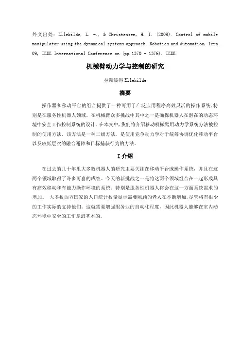
图、1 一台由赛格威RMP200和轻重量型库卡机器人组成的平台这项工作平台用于如图1所示,是由一个Segway与一家机器人制造商制造的RMP200轻机器人。
其有一个相对较小的轨迹和高机动性能的平台使它适应在室内环境移动。
库卡工业机器人具有较长的长臂和高有效载荷比自身的重量,从而使其适合移动操作。
当控制移动机械臂系统时,有一个选择是是否考虑一个或两个系统的实体。
在参考文献[1]和[2]中是根据雅可比理论将机械手末端和移动平台结合在一起形成一个单一的控制系统。
附录附录1英文原文Basic Machining Operations and Cutting Technology Basic Machining OperationsMachine tools have evolved from the early foot-powered lathes of the Egyptians and John Wilkinson's boring mill. They are designed to provide rigid support for both the workpiece and the cutting tool and can precisely control their relative positions and the velocity of the tool with respect to the workpiece. Basically, in metal cutting, a sharpened wedge-shaped tool removes a rather narrow strip of metal from the surface of a ductile workpiece in the form of a severely deformed chip. The chip is a waste product that is considerably shorter than the workpiece from which it came but with a corresponding increase in thickness of the uncut chip. The geometrical shape of workpiece depends on the shape of the tool and its path during the machining operation.Most machining operations produce parts of differing geometry. If a rough cylindrical workpiece revolves about a central axis and the tool penetrates beneath its surface and travels parallel to the center of rotation, a surface of revolution is produced, and the operation is called turning. If a hollow tube is machined on the inside in a similar manner, the operation is called boring. Producing an external conical surface uniformly varying diameter is called taper turning, if the tool point travels in a path of varying radius, a contoured surface like that of a bowling pin can be produced; or, if the piece is short enough and the support is sufficiently rigid, a contoured surface could be produced by feeding a shaped tool normal to the axis of rotation. Short tapered or cylindrical surfaces could also be contour formed.Flat or plane surfaces are frequently required. They can be generated by radial turning or facing, in which the tool point moves normal to the axis of rotation. In other cases, it is more convenient to hold the workpiece steady and reciprocate the tool across it in a series of straight-line cuts with a crosswise feed increment before each cutting stroke. This operation is called planning and is carried out on a shaper. For larger pieces it is easier to keep the tool stationary and draw the workpiece under it as in planning. The tool is fed at each reciprocation. Contoured surfaces can be produced by using shaped tools.Multiple-edged tools can also be used. Drilling uses a twin-edged fluted tool for holes with depths up to 5 to 10 times the drill diameter. Whether thedrill turns or the workpiece rotates, relative motion between the cutting edge and the workpiece is the important factor. In milling operations a rotary cutter with a number of cutting edges engages the workpiece. Which moves slowly with respect to the cutter. Plane or contoured surfaces may be produced, depending on the geometry of the cutter and the type of feed. Horizontal or vertical axes of rotation may be used, and the feed of the workpiece may be in any of the three coordinate directions.Basic Machine ToolsMachine tools are used to produce a part of a specified geometrical shape and precise I size by removing metal from a ductile material in the form of chips. The latter are a waste product and vary from long continuous ribbons of a ductile material such as steel, which are undesirable from a disposal point of view, to easily handled well-broken chips resulting from cast iron. Machine tools perform five basic metal-removal processes: I turning, planning, drilling, milling, and grinding. All other metal-removal processes are modifications of these five basic processes. For example, boring is internal turning; reaming, tapping, and counter boring modify drilled holes and are related to drilling; bobbing and gear cutting are fundamentally milling operations; hack sawing and broaching are a form of planning and honing; lapping, super finishing. Polishing and buffing are variants of grinding or abrasive removal operations. Therefore, there are only four types of basic machine tools, which use cutting tools of specific controllable geometry: 1. lathes, 2. planers, 3. drilling machines, and 4. milling machines. The grinding process forms chips, but the geometry of the abrasive grain is uncontrollable.The amount and rate of material removed by the various machining processes may be I large, as in heavy turning operations, or extremely small, as in lapping or super finishing operations where only the high spots of a surface are removed.A machine tool performs three major functions: 1. it rigidly supports the workpiece or its holder and the cutting tool; 2. it provides relative motion between the workpiece and the cutting tool; 3. it provides a range of feeds and speeds usually ranging from 4 to 32 choices in each case.Speed and Feeds in MachiningSpeeds, feeds, and depth of cut are the three major variables for economical machining. Other variables are the work and tool materials, coolant and geometry of the cutting tool. The rate of metal removal and power required for machining depend upon these variables.The depth of cut, feed, and cutting speed are machine settings that must be established in any metal-cutting operation. They all affect the forces, the power, and the rate of metal removal. They can be defined by paring them to the needle and record of a phonograph. The cutting speed (V) is represented by the velocity of- the record surface relative to the needle in the tone arm at any instant. Feed is represented by the advance of the needle radially inward per revolution, or is thedifference in position between two adjacent grooves. The depth of cut is the penetration of the needle into the record or the depth of the grooves.Turning on Lathe CentersThe basic operations performed on an engine lathe are illustrated. Those operations performed on external surfaces with a single point cutting tool are called turning. Except for drilling, reaming, and lapping, the operations on internal surfaces are also performed by a single point cutting tool.All machining operations, including turning and boring, can be classified as roughing, finishing, or semi-finishing. The objective of a roughing operation is to remove the bulk of the material as rapidly and as efficiently as possible, while leaving a small amount of material on the work-piece for the finishing operation. Finishing operations are performed to obtain the final size, shape, and surface finish on the workpiece. Sometimes a semi-finishing operation will precede the finishing operation to leave a small predetermined and uniform amount of stock on the work-piece to be removed by the finishing operation.Generally, longer workpieces are turned while supported on one or two lathe centers. Cone shaped holes, called center holes, which fit the lathe centers are drilled in the ends of the workpiece-usually along the axis of the cylindrical part. The end of the workpiece adjacent to the tailstock is always supported by a tailstock center, while the end near the headstock may be supported by a headstock center or held in a chuck. The headstock end of the workpiece may be held in a four-jaw chuck, or in a type chuck. This method holds the workpiece firmly and transfers the power to the workpiece smoothly; the additional support to the workpiece provided by the chuck lessens the tendency for chatter to occur when cutting. Precise results can be obtained with this method if care is taken to hold the workpiece accurately in the chuck.Very precise results can be obtained by supporting the workpiece between two centers. A lathe dog is clamped to the workpiece; together they are driven by a driver plate mounted on the spindle nose. One end of the Workpiece is mecained;then the workpiece can be turned around in the lathe to machine the other end. The center holes in the workpiece serve as precise locating surfaces as well as bearing surfaces to carry the weight of the workpiece and to resist the cutting forces. After the workpiece has been removed from the lathe for any reason, the center holes will accurately align the workpiece back in the lathe or in another lathe, or in a cylindrical grinding machine. The workpiece must never be held at the headstock end by both a chuck and a lathe center. While at first thought this seems like a quick method of aligning the workpiece in the chuck, this must not be done because it is not possible to press evenly with the jaws against the workpiece while it is also supported by the center. The alignment provided by the center will not be maintained and the pressure of the jaws may damage the center hole, the lathe center, and perhapseven the lathe spindle. pensating or floating jaw chucks used almost exclusively on high production work provide an exception to the statements made above. These chucks are really work drivers and cannot be used for the same purpose as ordinary three or four-jaw chucks.While very large diameter work pieces are sometimes mounted on two centers, they are preferably held at the headstock end by faceplate jaws to obtain the smooth power transmission; moreover, large lathe dogs that are adequate to transmit the power not generally available, although they can be made as a special. Faceplate jaws are like chuck jaws except that they are mounted on a faceplate, which has less overhang from the spindle bearings than a large chuck would have.Introduction of MachiningMachining as a shape-producing method is the most universally used and the most important of all manufacturing processes. Machining is a shape-producing process in which a power-driven device causes material to be removed in chip form. Most machining is done with equipment that supports both the work piece and cutting tool although in some cases portable equipment is used with unsupported work piece.Low setup cost for small Quantities. Machining has two applications in manufacturing. For casting, forging, and press working, each specific shape to be produced, even one part, nearly always has a high tooling cost. The shapes that may he produced by welding depend to a large degree on the shapes of raw material that are available. By making use of generally high cost equipment but without special tooling, it is possible, by machining; to start with nearly any form of raw material, so tong as the exterior dimensions are great enough, and produce any desired shape from any material. Therefore .machining is usually the preferred method for producing one or a few parts, even when the design of the part would logically lead to casting, forging or press working if a high quantity were to be produced.Close accuracies, good finishes. The second application for machining is based on the high accuracies and surface finishes possible. Many of the parts machined in low quantities would be produced with lower but acceptable tolerances if produced in high quantities by some other process. On the other hand, many parts are given their general shapes by some high quantity deformation process and machined only on selected surfaces where high accuracies are needed. Internal threads, for example, are seldom produced by any means other than machining and small holes in press worked parts may be machined following the press working operations.Primary Cutting ParametersThe basic tool-work relationship in cutting is adequately described by means of four factors: tool geometry, cutting speed, feed, and depth of cut.The cutting tool must be made of an appropriate material; it must be strong, tough, hard, and wear resistant. The tool s geometry characterized by planes and angles, must be correct for each cutting operation. Cutting speed is the rate at which the work surface passes by the cutting edge. It may be expressed in feet per minute.For efficient machining the cutting speed must be of a magnitude appropriate to the particular work-tool bination. In general, the harder the work material, the slower the speed.Feed is the rate at which the cutting tool advances into the work piece. "Where the work piece or the tool rotates, feed is measured in inches per revolution. When the tool or the work reciprocates, feed is measured in inches per stroke, Generally, feed varies inversely with cutting speed for otherwise similar conditions.The depth of cut, measured inches is the distance the tool is set into the work. It is the width of the chip in turning or the thickness of the chip in a rectilinear cut. In roughing operations, the depth of cut can be larger than for finishing operations.The Effect of Changes in Cutting Parameters on Cutting TemperaturesIn metal cutting operations heat is generated in the primary and secondary deformation zones and these results in a plex temperature distribution throughout the tool, work piece and chip. A typical set of isotherms is shown in figure where it can be seen that, as could be expected, there is a very large temperature gradient throughout the width of the chip as the work piece material is sheared in primary deformation and there is a further large temperature in the chip adjacent to the face as the chip is sheared in secondary deformation. This leads to a maximum cutting temperature a short distance up the face from the cutting edge and a small distance into the chip.Since virtually all the work done in metal cutting is converted into heat, it could be expected that factors which increase the power consumed per unit volume of metal removed will increase the cutting temperature. Thus an increase in the rake angle, all other parameters remaining constant, will reduce the power per unit volume of metal removed and the cutting temperatures will reduce. When considering increase in unreformed chip thickness and cutting speed the situation is more plex. An increase in undeformed chip thickness tends to be a scale effect where the amounts of heat which pass to the work piece, the tool and chip remain in fixed proportions and the changes in cutting temperature tend to be small. Increase in cutting speed; however, reduce the amount of heat which passes into the work piece and this increase the temperature rise of the chip m primary deformation. Further, the secondary deformation zone tends to be smaller and this has the effect of increasing the temperatures in this zone. Other changes in cutting parameters have virtually no effect on the power consumed per unit volume of metal removed and consequently have virtually no effect on the cutting temperatures. Since it has been shown that even small changes in cuttingtemperature have a significant effect on tool wear rate it is appropriate to indicate how cutting temperatures can be assessed from cutting data.The most direct and accurate method for measuring temperatures in high -speed-steel cutting tools is that of Wright &. Trent which also yields detailed information on temperature distributions in high-speed-steel cutting tools. The technique is based on the metallographic examination of sectioned high-speed-steel tools which relates microstructure changes to thermal history.Trent has described measurements of cutting temperatures and temperature distributions for high-speed-steel tools when machining a wide range of work piece materials. This technique has been further developed by using scanning electron microscopy to study fine-scale microstructure changes arising from over tempering of the tempered martens tic matrix of various high-speed-steels. This technique has also been used to study temperature distributions in both high-speed -steel single point turning tools and twist drills.Wears of Cutting ToolDiscounting brittle fracture and edge chipping, which have already been dealt with, tool wear is basically of three types. Flank wear, crater wear, and notch wear. Flank wear occurs on both the major and the minor cutting edges. On the major cutting edge, which is responsible for bulk metal removal, these results in increased cutting forces and higher temperatures which if left unchecked can lead to vibration of the tool and work piece and a condition where efficient cutting can no longer take place. On the minor cutting edge, which determines work piece size and surface finish, flank wear can result in an oversized product which has poor surface finish. Under most practical cutting conditions, the tool will fail due to major flank wear before the minor flank wear is sufficiently large to result in the manufacture of an unacceptable ponent.Because of the stress distribution on the tool face, the frictional stress in the region of sliding contact between the chip and the face is at a maximum at the start of the sliding contact region and is zero at the end. Thus abrasive wear takes place in this region with more wear taking place adjacent to the seizure region than adjacent to the point at which the chip loses contact with the face. This result in localized pitting of the tool face some distance up the face which is usually referred to as catering and which normally has a section in the form of a circular arc. In many respects and for practical cutting conditions, crater wear is a less severe form of wear than flank wear and consequently flank wear is a more mon tool failure criterion. However, since various authors have shown that the temperature on the face increases more rapidly with increasing cutting speed than the temperature on the flank, and since the rate of wear of any type is significantly affected by changes in temperature, crater wear usually occurs at high cutting speeds.At the end of the major flank wear land where the tool is in contact with the uncut work piece surface it is mon for the flank wear to be more pronounced than along the rest of the wear land. This is because of localised effects such as a hardened layer on the uncut surface caused by work hardening introduced by a previous cut, an oxide scale, and localised high temperatures resulting from the edge effect. This localised wear is usually referred to as notch wear and occasionally is very severe. Although the presence of the notch will not significantly affect the cutting properties of the tool, the notch is often relatively deep and if cutting were to continue there would be a good chance that the tool would fracture.If any form of progressive wear allowed to continue, dramatically and the tool would fail catastrophically, i. e. the tool would be no longer capable of cutting and, at best, the work piece would be scrapped whilst, at worst, damage could be caused to the machine tool. For carbide cutting tools and for all types of wear, the tool is said to have reached the end of its useful life long before the onset of catastrophic failure. For high-speed-steel cutting tools, however, where the wear tends to be non-uniform it has been found that the most meaningful and reproducible results can be obtained when the wear is allowed to continue to the onset of catastrophic failure even though, of course, in practice a cutting time far less than that to failure would be used. The onset of catastrophic failure is characterized by one of several phenomena, the most mon being a sudden increase in cutting force, the presence of burnished rings on the work piece, and a significant increase in the noise level.Mechanism of Surface Finish ProductionThere are basically five mechanisms which contribute to the production of a surface which have been machined. These are:(l) The basic geometry of the cutting process. In, for example, single point turning the tool will advance a constant distance axially per revolution of the workpiecc and the resultant surface will have on it, when viewed perpendicularly to the direction of tool feed motion, a series of cusps which will have a basic form which replicates the shape of the tool in cut.(2) The efficiency of the cutting operation. It has already been mentioned that cutting with unstable built-up-edges will produce a surface which contains hard built-up-edge fragments which will result in a degradation of the surface finish. It can also be demonstrated that cutting under adverse conditions such as apply when using large feeds small rake angles and low cutting speeds, besides producing conditions which lead to unstable built-up-edge production, the cutting process itself can bee unstable and instead of continuous shear occurring in the shear zone, tearing takes place, discontinuous chips of uneven thickness are produced, and the resultant surface is poor. This situation is particularly noticeable when machining very ductile materials such as copper and aluminum.(3) The stability of the machine tool. Under some binations of cutting conditions; work piece size, method of clamping ,and cutting tool rigidity relative to the machine tool structure, instability can be set up in the tool which causes it to vibrate. Under some conditions this vibration will reach and maintain steady amplitude whilst under other conditions the vibration will built up and unless cutting is stopped considerable damage to both the cutting tool and work piece may occur. This phenomenon is known as chatter and in axial turning is characterized by long pitch helical bands on the work piece surface and short pitch undulations on the transient machined surface.(4)The effectiveness of removing swarf. In discontinuous chip production machining, such as milling or turning of brittle materials, it is expected that the chip (swarf) will leave the cutting zone either under gravity or with the assistance of a jet of cutting fluid and that they will not influence the cut surface in any way. However, when continuous chip production is evident, unless steps are taken to control the swarf it is likely that it will impinge on the cut surface and mark it. Inevitably, this marking besides looking.(5)The effective clearance angle on the cutting tool. For certain geometries of minor cutting edge relief and clearance angles it is possible to cut on the major cutting edge and burnish on the minor cutting edge. This can produce a good surface finish but, of course, it is strictly a bination of metal cutting and metal forming and is not to be remended as a practical cutting method. However, due to cutting tool wear, these conditions occasionally arise and lead to a marked change in the surface characteristics.Limits and TolerancesMachine parts are manufactured so they are interchangeable. In other words, each part of a machine or mechanism is made to a certain size and shape so will fit into any other machine or mechanism of the same type. To make the part interchangeable, each individual part must be made to a size that will fit the mating part in the correct way. It is not only impossible, but also impractical to make many parts to an exact size. This is because machines are not perfect, and the tools bee worn. A slight variation from the exact size is always allowed. The amount of this variation depends on the kind of part being manufactured. For examples part might be made 6 in. long with a variation allowed of 0.003 (three-thousandths) in. above and below this size. Therefore, the part could be 5.997 to 6.003 in. and still be the correct size. These are known as the limits. The difference between upper and lower limits is called the tolerance.A tolerance is the total permissible variation in the size of a part.The basic size is that size from which limits of size arc derived by the application of allowances and tolerances.Sometimes the limit is allowed in only one direction. This is known as unilateral tolerance.Unilateral tolerancing is a system of dimensioning where the tolerance (that is variation) is shown in only one direction from the nominal size. Unilateral tolerancing allow the changing of tolerance on a hole or shaft without seriously affecting the fit.When the tolerance is in both directions from the basic size it is known as a bilateral tolerance (plus and minus).Bilateral tolerancing is a system of dimensioning where the tolerance (that is variation) is split and is shown on either side of the nominal size. Limit dimensioning is a system of dimensioning where only the maximum and minimum dimensions arc shown. Thus, the tolerance is the difference between these two dimensions.Surface Finishing and Dimensional ControlProducts that have been pleted to their proper shape and size frequently require some type of surface finishing to enable them to satisfactorily fulfill their function. In some cases, it is necessary to improve the physical properties of the surface material for resistance to penetration or abrasion. In many manufacturing processes, the product surface is left with dirt .chips, grease, or other harmful material upon it. Assemblies that are made of different materials, or from the same materials processed in different manners, may require some special surface treatment to provide uniformity of appearance.Surface finishing may sometimes bee an intermediate step processing. For instance, cleaning and polishing are usually essential before any kind of plating process. Some of the cleaning procedures are also used for improving surface smoothness on mating parts and for removing burrs and sharp corners, which might be harmful in later use. Another important need for surface finishing is for corrosion protection in a variety of: environments. The type of protection procedure will depend largely upon the anticipated exposure, with due consideration to the material being protected and the economic factors involved.Satisfying the above objectives necessitates the use of main surface-finishing methods that involve chemical change of the surface mechanical work affecting surface properties, cleaning by a variety of methods, and the application of protective coatings, organic and metallic.In the early days of engineering, the mating of parts was achieved by machining one part as nearly as possible to the required size, machining the mating part nearly to size, and then pleting its machining, continually offering the other part to it, until the desired relationship was obtained. If it was inconvenient to offer one part to the other part during machining, the final work was done at the bench by a fitter, who scraped the mating parts until the desired fit was obtained, the fitter therefore being a 'fitter' in the literal sense. J It is obvious that the two parts would have to remain together, and m the event of one having to be replaced, the fitting would have to be done all overagain. In these days, we expect to be able to purchase a replacement for a broken part, and for it to function correctly without the need for scraping and other fitting operations.When one part can be used 'off the shelf' to replace another of the same dimension and material specification, the parts are said to be interchangeable. A system of interchangeability usually lowers the production costs as there is no need for an expensive, 'fiddling' operation, and it benefits the customer in the event of the need to replace worn parts.Automatic Fixture DesignTraditional synchronous grippers for assembly equipment move parts to the gripper centre-line, assuring that the parts will be in a known position after they arc picked from a conveyor or nest. However, in some applications, forcing the part to the centre-line may damage cither the part or equipment. When the part is delicate and a small collision can result in scrap, when its location is fixed by a machine spindle or mould, or when tolerances are tight, it is preferable to make a gripper ply with the position of the part, rather than the other way around. For these tasks, Zaytran Inc. Of Elyria, Ohio, has created the GPN series of non- synchronous, pliant grippers. Because the force and synchronizations systems of the grippers are independent, the synchronization system can be replaced by a precision slide system without affecting gripper force. Gripper sizes range from 51b gripping force and 0.2 in. stroke to 40Glb gripping force and 6in stroke. GrippersProduction is characterized by batch-size being smaller and smaller and greater variety of products. Assembly, being the last production step, is particularly vulnerable to changes in schedules, batch-sizes, and product design. This situation is forcing many panies to put more effort into extensive rationalization and automation of assembly that was previouslyextensive rationalization and automation of assembly that was previously the case. Although the development of flexible fixtures fell quickly behind the development of flexible handling systems such as industrial robots, there are, nonetheless promising attempts to increase the flexibility of fixtures. The fact that fixtures are the essential product - specific investment of a production system intensifies the economic necessity to make the fixture system more flexible.Fixtures can be divided according to their flexibility into special fixtures, group fixtures, modular fixtures and highly flexible fixtures. Flexible fixtures are characterized by their high adaptability to different work pieces, and by low change-over time and expenditure.There are several steps required to generate a fixture, in which a work piece is fixed for a production task. The first step is to define the necessary position of the work piece in the fixture, based on the unmachined or base pan, and the working features. Following this, a bination of stability planes must be selected. These stability planes constitute the fixture configuration in which the work piece is fixed in the defined position, all the forces or torques are pensated, and the。
附录外文文献Design of Pinion Machine Tool-settings foSpiral Bevel Gearsby Controlling Contact Path andTransmission ErrorsCao Xuemei a,*,Fang Zongde a,Xu Hao b,Su Jinzhan aa:School of Mechatronics,Northwestern Polytechnic University,Xi’an 710072,China b:Zhongnan Transmission Machinery Works of Changsha Aviation Industries,Changsha 410200,ChinaReceived 16 September 2007;accepted 20 February 2008Abstract:This paper proposes a new approach to design pinion machine tool-settings for spiral bevel gears by controlling contact path and transmission errors.It is based on the satisfaction of contact condition of three given control points on the tooth surface.The three meshing points are controlled to be on a predesigned straight contact path that meets the pre-designed parabolic function of transmission errors.Designed separately,the magnitude of transmission errors and the orientation of the contact path are subjected to precise control.In addition,in order to meet the manufacturing requirements,we suggest to modify the values of blank offset,one of the pinion machine tool-settings,and redesign pinion machine tool-settings to ensure that the magnitude and the geometry of transmission errors should not be influenced apart from minor effects on the predesigned straight contact path.The proposed approach together with its ideas has been proven by a numerical example and the manufacturing practice of a pair of spiral bevel gears.Keywords:spiral bevel gear;contact path;transmission error;blank offset;tooth contact analysis1 IntroductionSpiral bevel gears are among the key components of aerospace power plants in general,helicopter gear drives in particular,which regard the meshing performance,endurance and reliability as critical safety factors.Therefore,designing spiral bevel gears has all the timebeen drawing close attention of researchers in many companies and institutions.The requirements of reducing noise level and increasing endurance of spiral bevel gears have raise formidable challenge to designers too.The bases for designing low-noise spiral bevel gears with localized bearing contacts were presented in related Refs..In order to absorb larger errors in alignment and have better stability,the contact path should be designed to be a straight line.As transmission errors are mostly blamed for noise and vibration in gearing systems,the transmission errors of parabolic type are considered to be able to absorb linear discontinuous effects caused by misalignment referred to as the main source of noise.In some cases,the machine tool-settings designed by way of the existing local synthetic method are well beyond the appropriate applicable range of the machine.In this paper,a new integrated approach is proposed on the base of meeting the contact conditions inclusive of the predesigned parabolic function of transmission errors and the specifically oriented straight contact path through three given control points on the tooth surface.As a result,as early as in the designing stage,the operating performance could be controlled.In addition,the values of blank offset can be so modified as to be within the appropriate range of the machine without any influenceon the magnitude of transmission errors apart from there being minor effects on the predesigned linear contact path.The proposed approach is based on the following assumptions:(1)The gear machine tool-settings are predetermined and can be adopted.(2)The main input parameters are η2 and m'21.Of them, η2 determines the orientation angle of the predesigned straight contact path,and m'21 the sec-ond derivative of the transmission function,which determines the predesigned magnitude of the parabolic function of transmission error.In this paper,the values of η2 and m'21 are given in advance,but,in practices,they can be optimized depending on the applied loads to obtain the favorable meshing performance through the loaded tooth contact analysis(LTCA).2 Active Tooth Surface Design by Three Given Meshing PointsAfter the three control meshing points have been determined on the gear surface by the predesigned straight contact path and the parabolic function of transmission errors,the pinionmachine tool-settings can be determined.2.1 Determination of three contact pointsFig.1 shows the three contact points on the gear tooth su rface.Γ2 is the pitch angle of the gear.The contact path is designed to be a straight line and η2 is the orientation of contact path.Fig.1 Three control meshing points and contact path.When the gear surface ∑2 rotates by φ02, φ12 andφ22,the pinion surface ∑1 contacts with it at meshing points M0,M1 and M2with rotational angles φ02, φ12 and φ22 respectively.Let the cycle of pinion meshing be 2π/Z1,where Z1is the tooth number of pinion,and then φ11=π/Z1+φ01and φ21=−π/Z1+φ01 can be determined.At the mean contact point M0,the instantaneous transmission ratio is equal to the gear ually this point is chosen to be in the middle ofthe tooth surface,and its location can be adjusted according to design requirements.The rotation angles of the gear φ02and the pinion at this point φ01,can be determined from the location and the meshing equation at M0.2.2 Determination of transmission errorsThe transmission error function is represented byδφ2=(φ2−φ02) −(φ1−φ01) Z1/ Z2 (1)Where φi(i=1,2)is the rotation angle of the pinion(i=1)or the gear(i=2)in the process of meshing,and Z i the tooth number of the pinion(i=1)or the gear(i=2).The parabolic function of transmission error is represented byδφ2= · m'21(φ1−φ01)2(2)where m'21 is the derivative of the transmission ratio.φ2 is determined as followsφ2=Z1(φ1−φ01)/Z2+φ02+· m'21(φ1−φ01)2(3)The rotation angles of gear φ12and φ22,at the meshing points M1 and M2,can be determined from Eq.(3).2.3 Determination of orientation of contact pathAs the contact path is designed to be a straight line,the three meshing points M0,M1 and M2are on it.The meshing equation between the gear surface ∑2and the pinion surface ∑1 at the contact point M1 should observen·ν12=f(θg,øg, φ12)=0 (4)where n and ν12 are the unit normal and the relative velocity at the meshing point, θg and øg represent the surface coordinates of the gear tooth surface.Based on the location of the contact point M0 and the given orientation of contact path η2,the location of the contact point M1can be determined.The location equation of contact point M1 isg(θg,øg, φ12)=0 (5)By solving Eqs.(3)-(5),the position vector and unit normal of the point M1 at the gear surface ∑2can be obtained.The position vector and the unit normal of the point M2at the surface ∑2 can also be determined the same way.2.4 Determination of ø11 and ø21Fig.2 shows the coordinate systems for pinion generation.The coordinate systems S m1,S c and S b are fixed on the machine.The pinion machine root angle γ1 determines the orientation of S b with respect to S m1.X G1 is the machine center to back for generation of pinion;E m1 the blank offset and X B1the sliding base.The cradle coordinate system S p rotates about the Z m1-axis.The angle øp is the current rotation angle of the cradle in the process of generation.The coordinate system S f is connectedrigid to the pinion head-cutter,which in the process of generation performs rotation with the cradle (transfer motion)and relative motion with respect toFig.2 Coordinate systems for pinion generation.the cradle about the Z f-axis.The movable coordinate system S1is connected rigid to the generated pinion and rotates about the X b-axis.The angle ø1 is the current rotation angle of pinion in the process of generation. ø11 and ø21 are the rotation angles of pinion in the process of generation at points M1and M2.By transforming the coordinate from S2to S c,the unit normal n c of contact points M1 and M2 in system S c can be determined.Then by transforming the coordinate from S f to S m1,the unit normal n m1 of pinion-cutter-generating surface in S m1 can be determined.Since the axis of S m1 is parallel to the axis of S c,the unit normal of contact point in the system S c is equal to that in the system S m1.The following equation holds true.n c (ø1) =n m1(θp+ ø p) (6)from which ø11 and ø21 can be determined.2.5 Determination of X G1,E m1, ø1p and ø2pThe position vectors r cf of points M1 and M2 in the system S c can be derived from their position vectors on pinion-cutter-generating surfaces by transforming the coordinate from S f to S c.The position vectors r c can be derived from the position vectors of contact points M1 and M2on the surface ∑2by transforming the coordinate from S2to S c.r cf and r c coincide with each other at the instantaneous point of contact M1(M2).The position vector equation is r cf=(X G1,E m1, øp,s p)=r c (7)As for the points M1and M2,the position vector equations,which are equivalent to six independent scalar equations with six unknowns,can beused to determine the six unknowns:X G1,E m1, ø1p, ø2p,s1p and s2p.Here ø1pand ø2p are the rotation angles of cradle in the process of generating contact points M1 and M2.2.6 Determination of r p,s r1,q1,X B1 and m p1From the given angle η2on the contact path ∑2,and the length of the major axis of the instantaneous contact ellipse,the principal curvatures and directions at mean contact point M0 for the pinion head-cutter can be determined with the local synthesis.Then the cutter point radius r p can be determined.Based on the position vectors for the point M0 in the systems S c and S m1,the machine tool-settings s r1,q1 and X B1 can be determined.Likewise,based on the unit normal for the point M0in the system S c and the equation of meshing between the pinion head-cutter and the pinion to be generated,the cutting ratio m p1 can be determined.2.7 Determination of modified rollThe modified roll means the cutting ratio not being constant in the process of generation.The rotation angle of the cradle øp and the rotation angle of the pinion to be generated ø1 are related by a polynomial function,usually,of the third orderø1=[øp−C(øp)2−D(øp)3] (8)where C and D are modified roll coefficients.As the rotation angles ø1p and ø2p of the cradle and the rotation angles ø11 and ø21 of the pinion in the process of generating points M1 and M2 are all known.It is possible to use Eq.(8)to determine the modified roll coefficients.3 Redesigning Pinion Machine Tool-settings Based on Blank OffsetIf the blank offset,calculated according to Section 2,is well beyond the appropriate applicable range of the machine,it should be modified,and the pinion machine tool-settings be redesigned on the result acquired in Section 2.3.1 Determination of X G1,r p and m p1Principal directions(e f, e h)and principal curvatures(k f,k h)of a pinion tooth surface ∑1 at the mean contact point M0 can be determined by localsynthesis between t he gear tooth surface ∑2 and the pinion tooth surface∑1.Then using the meshing equation of pinion and head-cutter on the mean contact point M0,the machine center to back X G1 can be determined.Based on the Rodrigues formula and the condition of continuous tangency of head-cutter surface ∑p and pinion tooth surface ∑1along the line,the following two equations can beobtainedα212=α11·α22 (9)α11·α23=α12·α13 (10)From Eq.(9),the principal curvatures k s of point M0on the cone surface of the head-cutter can be determined while the other principal curvature being zero.Then the cutter point radius r p can be determined.From Eq.(10),the ratio of pinion roll m p1 can be determined.3.2 Determination of modified roll coefficientsr(1)h(θp,øp,ø1)= r(2)h(θg,øg,ø1) (11)n(1)h(θp,øp,ø1)= n(2)h(θg,øg,ø1) (12)Eqs.(11)-(12)describe the continuous tangency of the pinion and the gear tooth surfaces ∑1and ∑2, the subscripts 1 and 2 denote the pinion tooth surface and the gear tooth surface,respectively.Eq.(11) indicates that the position vectors of the point on ∑1 and the point on ∑2coincide at the instantaneous contact point in the fixed coordinate system S h,and Eq.(12)that the surface unit normals do at the contact point.Eqs.(11)-(12)are equivalent to five independent scaler equations with five unknowns.The parameters θp and øp represent the surface coordinates of ∑1,and θg and øg of ∑2.The parameter ø1 denotes the rotation angle of pinion in the process of generation at the contact point.The rotation angles of gear φ12and φ22at the contact points M1and M2can be determined byEq.(3),and are chosen to be the input in solvingEqs.(11)-(12).Then ø11, ø21and ø1p, ø2p can be determined.By Eq.(8),the modified roll coefficients C and D can be determined.The solutions of Eqs.(11)-(12)are not unique.Rather,the different solution determines the different contact point under the same rotation angle of gear φ2.In order to keep the contact point as close to the predesigned contact point as possible,the corresponding parameters of the point M1(M2)from Section 2 should be chosen as the initial values of the five unknowns to solve Eq.(11)and Eq.(12).An example is taken to show the influences of modification of blank offset on the contact path,of which the design parameters are listed in Table 1.Fig.3(a)shows the contact pattern designed according to Section 2.The contact path is a straight line and the blank offset calculated is–27.604 mm.Then by assuming the blank offset to be 0 mm,the redesignaccording to Section 3 is accomplished on the base of the first design.Fig.3(b)shows the contact pattern.Table 1 Blank dataFig.3 Influences of blank offset on contact path.The redesign aims at making the values of blank offset within the appropriate applicable range of the machine.Since the rotation angles of pinion at control meshing points are known,and the corresponding rotation angles of gear can be determined from Eq.(3),the modification of blank offset does not change the magnitude of transmission errors. The nonlinear Eqs.(11)and(12)have multiple solutions.The parameters of control meshing points M1 and M2 calculated in active tooth surface design(see Sections 2.3 and 2.5)are used to be the initial values to solve equations,so the control meshing points redesigned can be as close to the corresponding points M1 and M2 as possible.Although the redesigned contact path has a very small curvature,it still comes extremely close to the straightline shape resulting from the function-oriented active tooth surface design.In order to absorb larger errors of misalignment, the contact path should be designed to be a straigh line.On the other hand,the values of blank offse depend on the appropriate applicable range of the machine.Therefore,the modification of blank offse should be within the appropriate applicable range of the machine and made to reduce the curvature of the contact path as much as possible.4 Example of Designing Spiral Bevel GearAn example of designing a spiral bevel gear has been accomplished to illustrate the proposed approach.The design parameters are listed in Table 1.The concave side of the pinion tooth surface and the convex side of the gear tooth surface are considered the driving and driven surfaces,respectively.On the working flank,the geometry of the transmission error is designed to be of a parabolic function;the magnitude of the transmission error is 8.25",and the predesigned contact path orientation is 22o from the root cone.On the non-working flank,the magnitude of the transmission error is designed to be 11.25"and the predesigned contact path orientation 14o from the root cone.Blank offset is assumed to be 0 mm.Table 2 and Table 3 show the machine tool-settings of the gear and the pinion.Table 2 Gear machine tool-settingsTable 3 Pinion machine tool-settingsThe results from tooth contact analysis(TCA) are shown in Fig.4,which include the adjusted contact pattern and the obtained function of transmission errors.Fig.4 Contact patterns and transmission errors.5 Experimenta lThe spiral bevel gear pair designed according to Section 4 is processed by the Phoenix 800PG grinding machine.The actual tooth surfaces are measured on the Mahr’s measur ement device.The theoretically calculated tooth surface is used as a baseline for comparison.Fig.5 compares the toothFig.5 Deviations of actual tooth surface from theoreticaltooth surfaces for gear and pinion.topographies,obtained from the mathematical model and the data measured on the real manufactured gears.For the gear,the maximum surface deviations are 0.015 mm on the convex side and 0.010 mm on the concave side,and for the pinion, the maximum surface deviations are 0.004 mm on the convex side and 0.004 mm on the concave side.Moreover,the maximum deviations are all located far away from the contact area while the deviations on the contact area are near zero.Fig.6 and Fig.7 show the real contact patterns on the working flank and the non-working flank,which are quite consistent with the theoretically calculated results.Fig.6 Contact patterns on working flankFig.7 Contact patterns on non-working flank.6 ConclusionsFrom the computer calculation,simulation and experiment,some conclusions can be made as follows:(1)The proposed approach to design pinion surfaces is based on controlling three meshing points.The geometry of transmission errors is designed to be a parabolic function and the magnitude can be calculated by derivation of transmission ratio m'21,an input variable.The contact path is designed to be a straight line and its orientation can be adjusted.The magnitude of transmission errors and the contact path are designed separately.This provides a better ground for the further design of the transmission errors under loads.(2)The values of blank offset can be so modified as to have no influences on themagnitude of transmission error apart from there being few of effects on the predesigned straight contact path.(3)On the Phoenix grinding machine,a spiral bevel gear pair is produced,whose meshing mark verifies the computer-calculated and simulation results.References[1]Litvin F L.Local synthesis and tooth analysis of face-milled of spiral bevel gears.NASA-CR-4342,1990.[2]Litvin F L.Gear geometry and applied theory.Englewood Cliffs:Prentice Hall,1994.[3]Lewicki D G,Handschuh R F,Henry Z S.Low-noise,high strength spiral bevel gears for helicopter transmission.Journal of Propulsion and Power 1994;10(3):356-361.[4]Zhang putering analysis of meshing and contact of gear real tooth surfaces.ASME Journal of Mechanical Design 1994;116(6):677-671.[5]Zhang Y,Litvin F L,Handschuh R puterized design of low-noise face-milled spiral bevel gears.Mechanism and Machine Theory 1995;30(8):1171-1178.[6]Lin C Y,Tsay C B,Fong Z H.Mathematical model of spiral bevel and hypoid gears manufactured by the modified roll method. Mechanism and Machine Theory 1997;32(1):121-136.[7]Litvin F L,Wang A G,Handschuh R puterized generation and simulation of meshing and contact of spiral bevel gears with improved geometry.Journal Computer Methods in Applied Me-chanics and Engineering 1998;158(1):35-64.[8]Lin C Y,Tsay C B,Fong Z puter-aided manufacturing of spiral bevel and hypoidgears by applying optimization tech-niques.Journal of Materials Processing Technology 2001;114(1): 22-35.[9]Simon V.Optimal machine tool settings for hypoid gears improving load distribution.ASME Journal of Mechanical Design 2001;123(12):557-582.[10]Fuentes A,Litvin F L,Woods B R,et al.Design and stress analysis of low-noise adjusted bearing contact spiral bevel gears.ASME Journal of Mechanical Design 2002;124(4):524-532.[11]Litvin F puterized design,simulation of meshing,and contact and stress analysis of face-milled formate generated spiral bevel gears.Mechanism and Machine Theory 2002;37(3): 441-459.[12]Argyris puterized integrated approach for design and stress of spiral bevel put Methods Appl Mech Engrg 2002;191(8):1057-1095.[13]Fang Z D.Tooth contact analysis of spiral bevel gears based on the design of transmission error.Acta Aeronautica et Astronautica Sinica 2002;23(3):226-230.[in Chinese][14]Cao X M,Fang Z D,Zhang J L.Function-oriented active tooth surface design of spiral bevel gears.Chinese Journal of Mechanical Engineering 2007;43(8):155-158.[in Chinese] [15]Cao X M,Fang Z D,Zhang J L.Analysis and design of the pinion machine settings for spiral bevel gears.China Mechanical Engineering 2007;18(13):1584-1587.[in Chinese] [16]Wang P Y,Fong Z H.Fourth-order kinematic synthesis for face milling spiral bevel gears with modified radial motion(MRM) correction.ASME Journal of Mechanical Design 2006;128(2): 457-467.[17]Medvedev V I,V olkov A E.Synthesis of spiral bevel gear transmissions with a small shaft angle.Journal of Mechanical Design 2007;129(9):949-959.[18]Fang Z D,Cao X M,Zhang J L.Measuring date processing of aviation spiral bevel gears by using coordinate measurement.Acta Aeronautica et Astronautica Sinica 2007;28(2):456-459.[in Chinese]Biographies:Cao Xuemei Born in 1970,her main research interestsinclude design,manufacture and measurement of spiral beveland hypoid gears.E-mail:2004xuemeicao@Fang Zongde Born in 1948,Ph.D.,professor.His main research interests include dynamics of structure,micro-air- craft design and CAE.E-mail:fauto@译文:通过控制接触的路径和传输误差来为螺旋锥轮设计齿轮机床设置曹雪梅a方宗德a徐昊b苏金展 aa:西北理工大学机电一体化中国西安邮编710072b:中南航空工业学院中国长沙邮编 4102002007年9月16日收到 2008年2月审核通过摘要:本文提出了一种通过控制接触的路径和传输误差来为螺旋锥齿轮设计齿轮机床设置的新方法。
An intelligent NC program processor forCNC system of machine toolYadong Liua,_, Xingui Guoa, Wei Lia, Kazuo Yamazakia,Keizo Kashiharab, Makoto FujishimabAbstract NC program interpreting is one of the most important tasks of CNC in machine tool system. The existing CNC systems only supportvendor-specific NC program input, which restrict the applying of other similar functional NC programs with different program format.Especially for those users owning several machine tools with different CNC from the same provider, the diversity of NC programsdramatically increases their cost and time on operator training and machine tool maintenance. In order to deal with the variety of NC program, an intelligent NC program processor (NCPP) is proposed in this paper.1. IntroductionIn the CNC system of modern machine tool, NCprogram interpreting is very important, which is in charge of the accurate resolving of machining intention generated from CAM system. The major function of NCPP is to decode the input into motion command and programmable logiccontroller (PLC) command, and send them to the motion control processor (MCP) and PLC of CNC separately in order to control the movement of the cutting tool and auxiliary machine logic. Most CNC systems can handle only one specific NC program format, while the diversity of NC programs always entangles the machine tool users,especially for those owning several machine tools with different CNC but from the same provider.2. Interface of NC program processorNCPP is one module of the CNC, which requires cooperation between different modules; therefore it’s quite necessary to clarify the interface before starting design. The purpose of NCPP is to translate the input NC program into machine instruction, such asmotion command, PLC command or simple parameter settings and error messages. NIST calls these outputs as Canonical Machining Functions.The canonical machining functions were devised with two objectivesin mind:_ All the functionality of common 3- to 5-axis machining centers had tobe covered by the functions; for any function a machining center can perform, there has to be a way to tell it to do that function._ It must be possible to interpret RS274-compatible NC program into canonical machining function calls.3. Conceptual model of proposed NCPPCompared to the traditional design, the major feature of this NCPPis the structure with separation of NCSD and processing engine.Within thisNCPP, different NC program could be interpreted in terms of different NCSD, while the processing engine keeps the same. For example, suppose the input NC program follows Fanuc specification, the engine will refer to the Fanuc NCSD to do interpretation. Next time, if a NC program following Mitsubishi specification is given, the same engine will refer to the Mitsubishi NCSD to interpret it. For the two cases, it can be seen that each time only different NCSD is chosen, while the processing engine does not change. Such a solution provides dramatic flexibility and stability for the NCPP development, only one set of software code of the processing engine needs to be maintained. Even if there is an input NC program following a NC specification which is not available in the existing NCSDs, a new NCSD can be generated and added easily without recompiling the source code of the processing engine..4. Design of proposed NCPPBased on the conceptual model of the proposed NCPP If looking inside the NCPP, the key portion is the interpreting (processing) engine mentioned before, from a compiler’s point of view, the engine can be divided into four steps in order to check and decode an input NC program.These four steps are:_ Lexical analysis, which checks the character-based error within a NC program._ Syntax analysis, which makes sure the logic relation within each block of NC program is correct._ Semantic analysis, which checks the inter-block logic correctness of a NC program._ Optimization and code generation, which decode block and generate the canonical machining functions.4.1. Lexical analysisThe major functionality of lexical analysis is to merge a sequence of characters from the input NC program intosequence of words, which is a high-level representation unit,Meanwhile, in this step, all blank and comments within the program will be deleted. After lexical analysis, a symbol table with the same information but more systematic compared to the original character-based program will be built. During analysis, all character-based error will be checked, for example whether the unacceptable address letters has been used or not. In this paper, one dictionary has been designed in this step to store all the valid address letters.4.2. Syntax and semantic analysisSyntax analysis is to determine if a sequence of words within a block is syntactically correct, it is also called intra-block check. It includes the range checking of the data portion of a word and the parameters format checking.Semantic analysis checks the major inter-block error,which means tomake sure whether the logical relationship among several blocks of NC program is correct or not, for example, the same group G/M word cannot appear more than once in a block; block/word sequence should be subject to the G/M word execution order table, spindle should be turned on before any cutting motion starts, etc.In order to design NCSD for syntax and semanticanalysis, three kinds of cases of NC blocks should be analyzed:Case 1: Extract data expression in each word of NCprogram. For example, ‘‘X [1+2_3–4/5], Zsin[30],#1 2.0 F #1’’ should be correctly decoded as ‘‘X6.2, Z0.5, F2.0’’. Case 2: Check syntax relation of words within each block. For example, within block ‘‘G17 G02 X10 Y20 I-10F15 S100 M03’’, Z-axis value should not appear since in_ Terms with quote symbol as header and ender are terminal symbol._ Interpreting an expression is to apply one or more of the syntax rules.NC language can be considered as one type of simple computer programming language; therefore it’s quite reasonable to use EBNF to represent the NC program syntax. Based on that, the structure of NCSD can be systematically defined.4.3.1. Syntax representation using EBNFBased on these EBNF representations, case 1 mentioned in Section 4.2 can be easily solved. The fig shows an example of how to interpret word ‘‘X[1+2_3–4/5]’’ using these EBNF representations, as shown in this figure, two stacks (first in last outFundamental EBNF representation of NC languagemechanism) are used: value stack and operator stack. The operator stack is subject to a rule: the priority of each item is always in a decreasing order while the execution with highest priority always happens first. Following is the ordered operation list of interpreting:(1) Apply first EBNF rule defined, read the symbol ‘[’ and push it into the operator stack.(2) Apply EBNF rule 2,1,7,9 in turn, read value ‘1’ and symbol ‘+’, and then push them into value stack and operator stack, respectively.(3) Continue to apply rule 1,7,9 twice, read ‘2’/‘3’ and ‘*’/‘_’ separately, and push them into corresponding stacks.(4) Since operator ‘*’ on the top of the operator stack has higher priority than its previous one ‘+’ and higher than the current one ‘_’, current value 3’ is used to execute multiplication with ‘2’ popped up from the value stack. The result is pushed back into the value stack, while current operator ‘_’ is pushed into the operator stack.(5) Continue the quite similar operation as above mentioned until the operator stack is empty and the last value ‘6.2’ is popped up from the value stack.(6) The last value ‘6.2’ is the final result. Therefore, ‘‘X [1+2_3–4/5’’ is interpreted as ‘‘X6.2’’.For case 2 and 3, Fig. 9 gives the EBNF representation of a general NC block while Fig. 10 shows partial syntax EBNF representation of each G/M/F/S/T word in a group manner.Let us use a NC blocks example shown before in Section4.2 to explain how these EBNF rules are being applied. For each block of the following example:‘‘N0010 G91 G40N0020 S100 M03N0030 G01 G53 X20 F15’’EBNF rules B.1 in Fig. 9 will be firstly applied, and then the detailed word EBNF rules in Fig. 10 will be applied. Now for the first block, assuming the default modal is G01, the rule 1, 2 and 6 of B.1 will take effective, then in rule 6 of B.1, rule B.3 is applied further and a correct check result will be returned. The similar procedure will be done for the second block. Then for the third block, as rule B.3 is applied, rule 4 of B.2 will be applied too, which is (G53_Expr ‘g53’+ABS_Mode+G40_Expr+‘g00’|’g01’). In this rule, ‘ABS_Mode’ (‘g90’) is required when ‘g53’ isEBNF representation of G/M word. given with ‘g01’, however, the third block does not satisfy this rule because ‘INC_Mode’ (‘g91’) is effective (this is given in the first block); therefore a syntax error is found.4.3.2. Syntax dictionary implementation using tool command languageThe above-mentioned EBNF-based syntax of NC program is programmed using tool command language (TCL), one kind of script language which works in an interpretive execution manner instead of compiling way. As all the NC program syntax is represented using TCL as TCL procedures, it will be loaded to work as the syntax dictionary of NCSD in the proposed NCPP.4.4. Processing engine design4.4.1. Conceptual model of processing engine. An event generator and an embedded TCL interpreter are involved to handle each input NC block in terms of the loaded syntax dictionary of NCSD.The event generator triggers the TCL interpreter by extracting words within a NC block according to priority.For each word’s syntax, a corresponding TCL procedure defined in syntax dictionary will be called by the TCL interpreter. The Syntax and semantic analysis will be done during this process; canonical machining functions will be generated too. The dictionary generator in this figure is used to generate the syntax dictionary from NC program syntax EBNFrepresentation whenever a new NC specification is given.4.4.2. Processing flowThe fig shows the complete processing flow of proposed NCPP using one NC block example:(1) Initialization of the environment, which involves initializing parameters of NCPP (such as tool information, tool offset, coordination origin etc), loading the NCSD and starting the embedded TCL interpreter(2) Suppose one block ‘‘N10 G94 G01 G90 X2 Y4 F5 M03 ‘‘is ready to process.(3) NCPP processing engine search for the WORD with highest priority within this block in terms of the priority rules table. In this case first is word G01 and second is M03. As shown in the figure, priority rules table gives the definition of priority of words as they explicitly appear in the same block. Basically, group 1 of G word has the highest priority, followed by group 0 and other groups. For example, if G01 (group 1) and G92 (group 0) both given in a block, G01 should be taken care first. In the same sense, G words precede F, M and T words. In addition, modal information has the same effect, which means that the G modal word from higher priority group takes effect, as there is no G word explicitly appearing in the block.5. Prototype system implementationSo far, a prototype system of proposed NCPP has been implemented using C and TCL. This prototype was developed based on an existing RS274NGC interpreter written by Thomas Kramer from NIST in 2000. The current version realized almost all the functionality proposed in this paper, while the dictionary generator of NCSD is still under developing. By using the standard RS274 and Fanuc specification NC program as input, the result of the developed prototype system shows that a successful design was obtained. After being processed by A NC program example with syntax errors proposed NCPP, two syntax errors are both detected out with error messages, as those shown in the fig in italic and bold fonts. The corresponding canonical machining functions of the given NC program are generated too.6. ConclusionAn intelligent NCPP is proposed for the CNC system of machine tool. It has separated NCSD and processing engine. NCSD varies in terms of different NC program format, while the engine is fixed. Based on this new structure, it is easy to adjust the CNC system to adapt to various NC program format by only updating the corresponding NCSD in NCPP. In this paper, the NCSD has been designed by using EBNF and implemented as TCL procedures.AcknowledgementsThe authors wish to express their sincere appreciation for the generous support from Mori Seiki Corporation which makes this research possible. We also owe our thanks to the work of Dr. Thomas Kramer from NIST, whose work laid a great foundation for this research project. Further readin g[1] Vickors GW, Ly MH, Oetter RG. Numerically controlled machine tools. Chichester, UK: Ellis Horwood; 1990.[2] Peter S. CNC programming handbook. Industrial Press; 2000.[3] Karen AL. Fundamentals of compilers—an introduction to computer language translation. Englewood Cliffs, NJ: Prentice-Hall; 1992. [4] Thomas RK. The NIST RS274/NGC Interpreter—version 3, ISD of NIST; 2000.[5] Frederick MP. Canonical machining functions, ISD of NIST; 1997[6] Ronald M. Writing compilers and interpreters—an applied approach; 1991.[7] ISO/IEC 14977:1996(E) The standard of extended BNF,1997.[8] John KO. TCL and the TK Toolkit. Reading, MA: Addison-Wesley; 1994.机床CNC系统的智能数控程序处理器Yadong Liua,_, Xingui Guoa 、 Wei Lia , Kazuo Yamazakia,Keizo Kashiharab,Makoto Fujishimab摘要NC程序编译是机床CNC 的最重要工作之一。

T WORD ERROR (T 码错误)LOW OIL LEVEL (油位低)SPINPLE FAULT (主轴故障)SPINDLE ALARM (主轴报警)EXTERNAL EMG STOP (急停按钮被按下)AC NOT READY (交流盘未准备好)SPINPLE LUBE FAULT (主轴润滑故障)T CODE ERROR (T代码出错,非法T代码)M CODE ERROR (M代码出错,非法M代码)SERVO NOT READY (伺服未准备好)NC NOT READY(NC没准备好)TURRET FAULT (转塔故障)TURRET LIMIT (转塔限位)DC 24V OPEN (直流24断开)+24V NOT READY(+24V没准备好)GRAR DRIFT (档位漂移)PLEASE AXIS RETURN HOME(轴未回零)PLEASE DRUM RETURN HOME(刀库未回零)AIRPRESSFAILURE(气压故障)UNCL TOOL FALL(松刀失败)AIR PRESSURE DROP (压缩空气压力过低)CLAMP TOOL FALL(夹刀失败)DRUM NOT PARKED(刀库未在原值)X ZERO POINT NOT REACHED (X 轴未回零)Y ZERO POINT NOT REACHED (Y 轴未回零)Z ZERO POINT NOT REACHED (Z 轴未回零)4TH ZERO POINT NOT REACHED (第4轴未回零)X AXIS OVERTRAVL(X轴超限)Y AXIS OVERTRAVL (Y轴超限)Z AXIS OVERTRAVL (Z轴超限)COUNTER SWITCH REEOR (计数开关故障)MASTERT RANSFER OVER TEMP (主变压器过热)Z AXIS NOT AT FIRST REF POSITION (Z轴未在第一参考点)SPINDLE ORIENTATION FALLURE (主轴定向失败)TOOL DESENT OR TOOL DATA REEOR (刀具数据错误)PLEASE UNLOAD THE TOOL ON SPRINELK (请卸下主轴上的刀)PLEASE LOAD TOOL ON APINDLE (请装上主轴上的刀)A AXIS UNCLAMP FAIL (A 轴松开失败)A AXIS CLAMP FAIL (A 轴夹紧失败)DRUM OUT TO APRONDLEIS FALL (刀库摆向换刀位失败)MG SWING OVERLOAD(刀库摆动过载)DRUM BACK PARK IS FALL (刀库摆回原始位失败)TURRENT MOTOR1 OVERLOAD (刀库移动电机过载)COOLANT MOTOR OVERLOAD (冷却泵过载)DRUM ATC FAULT (自动换刀失败)TOOLS UNLOCKED (刀具未锁紧)BATTERY ALARM (电池报警)DRUM POSITION SWITCH ERROR (刀库位置检测开关故障)DRUM NOW NOT AT PARK (刀库未在原始位置)IT DANGOU TO MOVE DRUM (刀库禁动)POT UO FAILOR POT NOT AT UP POSITION (刀套未在水平位)POT DOWN FAIL (刀套翻下动作失败)IT IS DANGOUR TO MOVE ARM (机械手禁动)THE SPINDLE STATU IS ERROR (主轴状态错误)ARM MOTOR OR ARM SWITCH FALL (机械手或机械手开关故障)CENTRE LUBRICATION FALL (中心润滑故障)THE WORK NOT CLAMPED (工件未夹紧)AUTO TOOL CHANGE FAULT (自动换刀失败)TOOL DATA OUT OF RANGE (指令刀具号超出范围)THE ORDER TOOL NOW IN SPINDLE (目标刀具在主轴上)THE THREE SPINDLE SWITCH FAULT (主轴上的接近开关)THE CENTRE COOLANT IS LOWER (刀具内冷泵液位过低)DRUM RETURN 1# POSITION FAULT (刀库自动回零失败)SPINDLE OVERLOAD (主轴过载)TURRENT MOTOR OVERLOAD (刀盘转动电机过载)CHIP CONVEYER OVERLOAD (拉屑器过载)HARD LIMIT OR SERVO ALARM (硬限位或伺服报警)NO LUB OIL (无润滑油)INDEX HEAD UNLOCKED (分度头未锁紧)MT NOT READY(机床没准备好)MG OVERLOAD (刀库过载)LUB EMPTY(润滑无油)AIR PRESSURE(气压不足)COOLANT NOT READY(冷却没准备好)LUBE EMPTY(油雾油位低,润滑油位低)LUB PRESSURE LOW(润滑压力低)CONVEY VERLOAD(排屑过载)LUB OVERLOAD(润滑过载)LUBE PRESSURE LOW(油雾压力低)SERIAL SPINDLE ALARM (串行主轴报警)NC BATTERY LOW ALARM(NC电池低报警)MAGAZINE MOVE LIMIT SWITCH ERRORSPINDLE TOOL UNLAMP POSITION LIMIT SWITCH ERROR MAGAZINE NOT IN POSITION OR SENSOR ERRORAIR PRESSURE LOW ALARM(气压低报警)MOTOR OVERLOAD(电机过载)T CODE > MAGAZINE TOOLST CODE < 1 ERROR5TH AXIS HARDWARE OVERTRAVER LIMIT ERRORDOOR IS OPENED(开门)LUB PRESSURE SWITCH ERROR(油压开关错误) SPINDLE OIL COOLANT UNIT ERRORSPINDLE LOAD ABNORMAL(主轴负荷异常)TRANSDUCER ALARM(传感器报警)BED-HEAD LUBRICATE OFF(床头润滑关闭)EMG OFFHYDRAULIC CHUCK PRESS LOW(液压夹头压力低)HYDRAULIC TAIL PRESS LOW(液压尾座压力低)LUB 0IL LOW(油压低)TURRET CODE ERROR(转塔码错误)TURRET RUN OVERTIME(转塔运行超时)MANUAL HANDLE INTERRUPTTRY TO RUN SPINDLE WHILE CHUCK NOT LOCK TRY TO RUN SPINDLE WHILE TAIL NOT LOCK SPINDLE NEUTRAL GEARMAGAZINE ADJUSTHYDRAULIC NOT RUNSAFETY DOOR BE OPENEDSAFETY DOOR NOT CLOSENOT ALL AXIS HAVE GONE BACK REFIN ADJUST,IGNORE GOING BACK REFAFTER EXCHANGE TOOL,CYCLE STARTATC MOTOR QF16 OFFX AXIS IS LOCKED(X 轴被锁定)Y AXIS IS LOCKED(Y 轴被锁定)Z AXIS IS LOCKED(Z 轴被锁定)A AXIS IS LOCKED(A 轴被锁定)SPINDLE MOTOR FAN QF26 OFF(主轴电机风扇QF26关闭)关注我们的微信公众号shukongzhpngguo,获取更多数控技术文章。
附录A 英文原文Machine tool spindle unitsA.1 IntroductionMachine tool spindles basically fulfill two tasks:rotate the tools (drilling, milling and grinding) or work piece (turning) precisely in space transmit the required energy to the cutting zone for metal removalObviously spindles have a strong influence on metal removal rates and quality of the machined parts. This paper reviews the current state.and presents research challenges of spindle technology.A.1.1.Historical reviewClassically, main spindles were driven by belts or gears and the rotational speeds could only be varied by changing either the transmission ratio or the number of driven poles by electrical switches.Later simple electrical or hydraulic controllers were developed and the rotational speed of the spindle could be changed by means of infinitely adjustable rotating transformers (Ward Leonard system of motor control).The need for increased productivity led to higher speed machining requirements which led to the development of new bearings, power electronics and inverter systems. The progress in the field of the power electronics (static frequency converter) led to the development of compact drives with low-cost maintenance using high frequency three-phase asynchronous motors.Through the early 1980’s high spindle speeds were achievable only by using active magnetic bearings. Continuous developments in bearings, lubrication, the rolling element materials and drive systems (motors and converters) have allowed the construction of direct drive motor spindles which currently fulfill a wide range of requirements.A.1.2. Principal setupToday, the overwhelming majority of machine tools are equipped with motorized spindles. Unlike externally driven spindles, the motorized spindles do not require mechanical transmission elements like gears and couplings.The spindles have at least two sets of mainly ball bearing systems. The bearing system is the component with the greatest influence on the lifetime of a spindle. Most commonly the motor is arranged between the two bearing systems.Due to high ratio of ‘power to volume’ active cooling is often required, which is generally implemented through water based cooling. The coolant flows through a cooling sleeve around the stator of the motor and often the outer bearing rings.Seals at the tool end of the spindle prevent the intrusion of chips and cutting fluid. Often this is done with purge air and a labyrinth seal.A standardized tool interface such as HSK and SK is placed at the spindles front end. A clamping system is used for fast automatictool changes. Ideally, an unclamping unit (drawbar) which can also monitor the clamping force is needed for reliable machining. If cutting fluid has to be transmitted through the tool to the cutter, adequate channels and a rotary union become required features of the clamping system.Today, nearly every spindle is equipped with sensors for monitoring the motor temperature (thermistors or thermocouples) and the position of the clamping system. Additional sensors formonitoring the bearings, the drive and the process stability can be attached, but are not common in many industrial applications.A.1.3. State of the artSpindles with high power and high speeds are mainly developed for the machining of large aluminum frames in the aerospace industry. Spindles with extremely high speeds and low power are used in electronics industry for drilling printed circuit boards (PCB).A.1.4. Actual development areas in industryCurrent developments in motor spindle industrial application focus on motor technology, improving total cost of ownership(TCO) and condition monitoring for predictive maintenance Another central issue is the development of drive systems which neutralize the existing constraints of power and output frequency while reducing the heating of the spindle shaft.Particular attention was paid to the increase of the reliable reachable rotational speeds in the past. However, the focus has changed towards higher torque at speeds up to 15,000 rpm. Because of Increased requirements in reliability, life-cycle and predictable maintenance the ‘condition monitoring’ systems in motor spin dles have become more important. Periodic and/or continuous observation of the spindle status parameters is allowing detection of wear, overheating and imminent failures.Understanding the life cycle cost (LCC) of the spindles has steadily gained importance in predicting their service period with maintenance, failure and operational costs.2. Fields of application and specific demandsSpindles are developed and manufactured for a wide range of machine tool applications with a common goal of maximizing the metal removal rates and part machining accuracy.The work materials range from easy to machine materials like aluminum at high speeds with high power spindles, to nickel and titanium alloys which require spindles having high torque and stiffness at low speeds. Cutting work materials with abrasive carbon or fiber-reinforced plastics (FRP) content need good seals at the spindle front end.Spindles for drilling printed circuit boards operate in the angular speed range of 100,000 to 300,000 rpm. The increase in productivity and speed in this application field over the last few years was possible with the development of precision air bearings.Spindles used in die and mould machining have to fulfill the roughing operations (high performance cutting, HPC) at high feed rates as well as the finishing processes (high-speed cutting, HSC) at high cutting speeds. Depending on the strategy and the machinery of the mould and die shop either two different machine tools equipped with two different spindles are used or one machine is equipped with a spindle changing unit. Another possibility is to use a spindle which can fulfill both, HSC and HPC conditions, but this still remains a compromise regarding overall productivity.Aerospace spindles are defined by high power as well as high rotational speeds. Today’s spindles allow a material removal rate(MRR) of more than 10 l of aluminum per minute.Grinding is a finishing operation where high accuracy is necessary, which requires stiff spindles with bearings having minimum runout. The present internal cylindrical grinding spindles have a runout requirement of less than 1 mm.Spindle units which are used mainly for boring and drilling operations require high axial stiffness, which is achieved by using angular contact bearings with high contact angles. On the contrary, high-speed milling operations use spindles with bearings having small contact angles inorder to reduce the dependency of radial stiffness on the centrifugal forces.Contemporary machining centers tend to have multi functions where milling, drilling, grinding and sometimes honing operations can be realized on the same work piece. The bottleneck for the enhancement of the multi-technology machines is still the spindle, which cannot satisfy all the machining operations with the same degree of performance. Reconfigurable and modular machine tools require interchangeable spindles with standardized mechanical, hydraulic, pneumatic and electrical interfaces.A.3. Spindle analysisThe aim of modeling and analysis of spindle units is to simulate the performance of the spindle and optimize its dimensions during the design stage in order to achieve maximum dynamic stiffness and increased material removal rate with minimal dimensions and power consumption. The mechanical part of the spindle assembly consists of hollow spindle shaft mounted to a housing with bearings. Angular contact ball bearings are most commonly used in high-speed spindles due to their low-friction properties and ability to withstand external loads in both axial and radial directions. The spindle shaft is modeled by beam, brick or pipe elements in finite element environment. The bearing stiffness is modeled as a function of ball bearing contact angle, preload caused by the external load or thermal expansion of the spindle during operation. The equation of motion is derived in matrix form by including gyroscopic and centrifugal effects, and solved to obtain natural frequencies, vibration mode shapes and frequency response function at the tool attached to the spindle. If the bearing stiffness is dependent on the speed, or if the spindle needs to be simulated under cutting loads, the numerical methods are used to predict the vibrations along the spindle axis as well as contact loads on the bearings.Spindle simulation models allow for the optimization of spindle design parameters either to achieve maximum dynamic stiffness at all speeds for general operation, or to reach maximum axial depth of cut at the specified speed with a designated cutter for a specificmachining application. The objective of cutting maximum material at the desired speed without damaging the bearings and spindle is the main goal of spindle design while maintaining all other quality and performance metrics, e.g. accuracy and reliability.doe s not always lead to accurate identification of the spindle’s dynamic parameters;A.3.2. Theoretical modelingTheoretical models are based on physical laws, and used to predict and improve the performance of spindles during the design stage. The models provide mathematical relation between the inputs F (force, speed) and the outputs q (deflections, bearing loads, and temperature). The mathematical models can be expressed in state space forms or by a set of ordinary differential equations. In both cases linear or nonlinear behavior of the spindles can be modeled.A.3.2.1. Mechanical modeling of shaft and housingFinite element (FE) methods are most commonly used to model structural mechanics and dynamics of the spindles. The method is based on discretization of the structure at finite element locations by partial derivative differential equations. The analysis belongs to the class of rotor-dynamic studies where the axis-symmetric shaft is usually modeled by beam elements, which lead to construction of mass (Me) and stiffness (Ke) matrices.Timoshenko beam element is most commonly used because it considers the bending, rotary inertia and shear effects, hence leads to improved prediction of natural frequencies and mode shapes of the spindle .The element PIPE16 of the commonly known FEA software ANSYS is alsoan implementation of the Timoshenko theory and use the mass matrix and stiffness matrix As an example in the finite element model in Fig. 1, the black dots represent nodes, and each node has three Cartesian translational displacements and two rotations . The pulley is modeled as a rigid disk, the bearing spacer as a bar element, and the nut and sleeve as a lumped mass. The spindle in this case has two front bearings in tandem and three bearings in tandem at the rear. The five bearings are in overall back-to-back configuration. The tool is assumed to be rigidly connected to the tool holder which is fixed to the spindle shaft rigidly or through springs with stiffness in both directions translation and rotation. The flexibility of the spindle mounting has to be reflected in the model of the spindle-machine system. Springs are also used between the spindle housing and spindle head, whose stiffness is obtained from experience.Fig. 1. The finite element model of the spindle-bearing-machine-tool system附录 B 中文翻译机床主轴单元B.1.介绍机床主轴基本上完成两个任务:在空间精确的旋转刀具(钻削,铣削,磨削)或工件(车削)。
PLC模块控制回转工作台在三轴数控铣床铣削螺旋伞齿轮中的应用S. Mohsen Safavi & S. Saeed Mirian & Reza Abedinzadeh & Mehdi KarimianReceived: 25 November 2008 / Accepted: 23 November 2009 # Springer-Verlag London Limited 2009摘要当今,数控机床在机电一体化领域中得到了日益广泛的应用。
机械、电气和数据处理系统与数控技术相结合,引领了新的生产加工理念。
近年来,数控技术的发展已将非线性校正技术在切削弧齿锥齿轮中的应用变为可能。
在本文中,我们将尝试采用带有外加PLC模块分度台的三轴数控铣床,运用带有索引工作界面的通用铣床的传统连续多重切削方法来加工制造出这个螺旋伞齿轮。
该研究包括(a)弧齿锥齿轮的几何建模,(b)运用CAD/CAE系统进行传统或新型非传统方案的模拟仿真,(c)数控加工工艺的设计与PLC编程,(d)通过三轴数控铣床的实验切削来探索新方案的正确性。
结果表明,开发的螺旋伞齿轮实验切削方案不仅与先进数控加工相比成本更低,而且相比传统切削,加工齿轮的时间也较短。
因此,在螺旋伞齿轮加工领域,这是一个很经济的方案。
关键词:齿轮加工,螺旋伞齿轮,CAD/CAM/CAE,数控技术,PLC,交流电动机,逆变,接近传感器,光电传感器,旋转编码器1 引言齿轮是工业机械领域中重要的精密机构,在平行轴、横向交叉或非交叉轴之间用于传递机械功率和机械运动。
虽然有时会看不见,但齿轮仍是我们工业文明中最重要的机械元件之一。
在各式各样的条件下,齿轮会以几乎达到无限的速率运转。
得到发展的齿轮加工设备与工艺流程已经非常先进与成熟。
无论大批量生产还是小批量生产,无论在小型车间还是分批处理的加工车间,加工齿轮的流程按顺序都需要以下四步操作:(1)下料(2)切齿(3)热处理(4)研磨根据它们的类型、应用范围及强度和刚度要求,通常经过铸造、挤压、锻造、粉末冶金、注塑加工和滚齿加工来完成齿轮的加工制造。
外文翻译机床数控改造_Machine tool numerical control reformsFirst, CNC systems and the development trend of history一、数控系统发展简史及趋势1946 birth of the world's first electronic computer, which shows that human beings created to enhance and replace some of the mental work tools. It and human agriculture, industrial society in the creation of those who merely increase compared to manual tools, from a qualitative leap for mankind's entry into the information society laid the foundation. Six years later, in 1952, computer technology applied to the machine in the United States was born first CNC machine tools. Since then, the traditional machine produced a qualitative change. Nearly half a century since the CNC system has experienced two phases and six generations of development.1946年诞生了世界上第一台电子计算机,这表明人类创造了可增强和部分代替脑力劳动的工具。
数控机床英语词汇介绍数控机床是一种专门用来加工工件的机床,它通过数控系统控制工具或工件相对位置运动,从而实现加工目的。
下面是一些与数控机床相关的英语词汇介绍。
1. Numerical Control System(数控系统)Numerical Control System,简称NC系统,是数控机床的核心部分,也是数控技术的基础。
它通过将数字指令输入到机床控制器中,再根据指令控制加工工具或工件的运动,从而实现精确加工。
2. Computer Numerical Control(计算机数控)Computer Numerical Control,简称CNC,是NC系统的一种,也是数控机床常见的控制方式。
CNC系统使用计算机来控制加工工具或工件的运动,可以实现非常复杂的加工操作。
3. Machining Center(加工中心)Machining Center是一种多轴CNC数控机床,可以在同一台机床上完成钻孔、铣削、镗孔等多种加工操作。
它配备了多个电动主轴和自动换刀装置,可以实现自动化的生产加工。
4. Turning Center(车削中心)Turning Center是一种CNC车床,可以在同一台机床上实现多种车削操作。
它配备了自动刀架、自动工件夹持装置等设备,可以实现高效的车削加工。
5. CNC Programming(CNC编程)CNC Programming是指将要加工的零件图纸转换为机器能够理解的数字控制指令的过程。
在CNC编程中,我们需要使用特定的编程语言,对每个加工步骤进行编程,以实现所需的加工效果。
6. Axis(轴)Axis是数控机床上的运动轴,可以分为X轴、Y轴、Z轴和A轴、B轴、C轴等。
X、Y、Z轴分别用于控制机床上下、左右、前后的运动,而A、B、C轴则用于控制工具或工件的旋转。
7. Servo Motor(伺服电机)Servo Motor是数控机床上的关键部件之一,它配合伺服驱动器可以控制机床各轴的精确运动。
外文原文:Dimensional ControlIn the early days of engineer, the mating of parts was achieved by machining one part as nearly as possible to the required size, machining the mating part nearly to size, and then completing its machining, continually offering the other part to it, until thedesired relationship was obtained. If it was inconvenient to offer one part to the other part during machining, the final work was done at the bench by a fitter, who scraped the mating parts until the desired fit was obtained, the fitter therefore being a ‘fitter’in the literal sense. It is obvious that the two parts would have to be done all over again. In these days, we expect to be able to purchase a replacement for a broken part, and for it to function correctly without the need for scraping and other fitting operations. When one part can be used ‘off the shelf’to replace another of the same dimension and material specification, the parts are said to be to be interchangeable. A system of interchangeability usually lowers the production costs, as there is no need for an expensive ‘fiddling’operation, and it also benefits the customer in the event of the need to replace worn parts. It also, however, demands that the dimension of mating parts be specified, and that dimensional variations, due to machine and operator shortcomings, be taken into account. Some form of inspection must be introduced to ensure that the manufacture is controlled; this is particularly important, because dimensional errors may not be revealed until some time has elapsed, and often many miles from the place where the machining was done.1. Tolerance and Limits of sizeSince it is accepted that it is virtually impossible to manufacture a part without error, or in the rare event of a part being without error, to be able to proclaim it to be perfect (because the measuring instruments are subject to errors), it is necessary to indicate the maximum errors permitted. The draughtsman must indicate the largest and smallest sizes that the limits of size, and the difference between them is called the tolerance, the actual tolerance must be increased with size. The tolerance should be as large as possible, to keep the cost to a minimum.The method of indicating, on a drawing, the permitted tolerance depends mainly upon the type of operation involved, but local preference must also be taken into account. The following examples will illustrate some of the methods used,(1) Unilateral limits. These are usually used when the distance between two faces, or the diameter of a hole or shaft id specified. For example, when a diameter is being ground, the machinist would prefer to aim at the largest size permitted, so that, in the event of his reaching a diameter that is just a little larger than the maximum size permitted, he can take another cut,knowing that he can use up the whole of the tolerance before the job is rejected. A draughtsman might dimension a nominal 75-0.012 mm diameter shaft as D75. Similarly, a nominal 75mm hole might dimensioned as D75-0.012, the same reasoning applies as for shafts.(2) Bilateral limits. These are usually applied when, for example, the position of a hole is specified. The machine operator may position he hole nearer the datum or further from the datum than intended, he must aim between the limits of position, so that the maximum error can be made without causing the part to be rejected. The center distance between two holes would therefore be specified as, for example, 100+0.02mm.2. Fits are concerned with the relationship between two parts. Consider a shaft and a hole combination: if the shaft is larger than the hole, the condition is said to be of interference; and if smaller than the hole, the condition is said to be of clearance. The interference may be such that the two parts can be assembled only by shrinking, or it may be very slight, so that the parts can be assembled by hand-operated press. Similarly, the clearance can be slight, so that the shaft can rotate easily in the hole, or be large, so that there is ample clearance for bolts to pass through.In order that the precise condition is ensured, the limits of size of both the shaft and the hole must be stipulated.(1) Classes of fit. These are classified as follows.Clearance fit. When the limits of size of both the hole and the shaft are such that the shaft is always smaller than the hole, the fit id said to be a clearance fit.Interference fit. When the limits of size of both the hole and the shaft are such that the shaft is always larger than the hole, the fit id said to be a interference fit.Transition fit. When the limits of size of both the hole and the shaft are such that the condition may be clearance or interference, the fit id said to be a transition fit.(2) Hole-based system and Shaft-based system. In order to obtain a range of degrees of clearance, and degrees of interference, it is necessary to use a wide variation of hole sizes and shaft sizes. For example, a manufacturing company could be making a number of parts, all of a nominal 25-mm diameter, but which are all slightly different in actual limits of size, to suit the actual fit required of each pair of parts. This situation could mean that a large number of drills, reamers, gauges, etc. were required.It is logical that, to reduce this number, a standard hole could be used for each nominal size, and the variation of fit e obtained by making the mating shaft smaller or larger than the hole. This is known as a hole-based system. Alternatively, a standard shaft could be used for each nominal size, and the variation of fit is obtained by making the mating hole larger or smaller, as required. This is known as a shaft-based system. a hole-based system is usually preferred, because it standardizes “fixed size”equipment such as reamer and pluggauges; but a shaft-based system is usually also provided, because sometimes it is moreconvenient to employ a common shaft to which a number of components is assembled, each witha different fit, and sometimes it is convenient to use bar stock without further machining.3. Systems of limits and fits It is convenient to establish a standardized system of limits and fits, not only to eliminate the need for the draughtsman to determine the limits each time an assembly is detailed, but also to standardize the tools and gauges required. A system of limits and fits should cater for a wide range of nominal sizes. To satisfy the various needs of industry, and should cater for a wide range of quality of work. The system should, if possible, be tabulated, to save the user the trouble of having to calculate the limits of size to suit of the class of fit, the quality of the work, and the size of the part.4. British Standard 4500: 1969, ISO limits and fitsThis standard replace BS 4500 is essentially a revision of BS 1961 to bring the British Standard into line with the latest recommendations of the International Organization for Standardization (ISO). The system refers to holes and shafts, but these terms do not only apply to cylindrical parts but can equally well be applied to the space contained by. Or containing, two parallel faces or tangent planes. The system is tabulated,and covers sizes up to 3150mm.The Numerical Control’s developmentThe first electronic computer in the world emerged in 1946, this indicates the mankind has created the tool that can strengthen and replace the mental labour partly . It, and mankind those that create to strengthen tool of manual labor compare among agriculture, industrial society, the qualitative leap has arisen , has established the foundation that the mankind enters the information-intensive society . 6 years later, namely in 1952, the technology of the computer was applied to the lathe , the first numerical control lathe has emerged in U.S.A.. From then on, the traditional lathe had produced the change of the quality. In nearly half a century, the numerical control system went through two stages and six generations' development The numerical control lathe is regarded as the integrated typical products of electromechanics, play an enormous role among mechanical manufacturing industry , solve structure complicated , accurate , batch little , changeable processing problem of part in the modern machine-building well, and can stabilize the processing quality of the products , improve production efficiency by a large margin . But seen from situation which enterprises face at present, because the numerical control lathe price is relatively expensive, ambassador's enterprises are unable to do what one wants very much to do to relatively make the investment once only. Our country can yet be regarded as a kind of better good plan to the numerical control transformation of the ordinary lathe as the lathe big country . This text proposes to the domestic enterprise's current situation at present the economic numerical control of the simple and easy type transforms the thinking and design method for technical staff of numerical control's reference.Numerical control transformation mean to ordinary lathe some position make certain transformation generally, match the numerical control device, thus make the lathe have working ability of numerical control, its purpose is for improving machining accuracy of the old equipment and production efficiency, adapt to many variety and production , short run of part , can make industrial grade can process the high-quality part too than low worker at the same time, reduce investment of technological transformation of the equipment ,etc..Price performance on all these for improving been for lathe than,namely last mechanical performance and the working ability not higher with less money. So transform ordinary lathe as numerical control lathe whether one improve numerical control effective way of rate. Generally speaking, carry on the transformation concrete method of numerical control to the existing ordinary lathe, main transmission make change seldom, is it adopt high-accuracy ball guide screw is it is it give axle already existing ordinary guide screw to enter to replace to enter the transmission of giving. Machinery some transformation after finishing , mix M C S - 51 one-chip computer as numerical control system , with walk into electrical machinery urge the component,first class to moderate gear wheel urge X , sport , Z of axle. In our country in the numerical control lathe is transformed , the microcomputers mostly adopt M C S - type 51 one slice of microcomputers of systematic form, it is a result of very large scale integration development, widely used in the controlled field, develop very fast.According to the function level of the numerical control system , can divide the numerical control system into high , middle and low three to block , the low-grade numerical control system can be regarded as the economy numerical control system. The economy numerical control system is as to standard numerical control system, different periods, the meaning of different countries and regions is different. According to practising the instructions for use of the lathe, rational reduced system, lower costs , can be called economily. Different from the economy numerical control system , call the numerical control system with more complete function numerical control system of the whole function, or is called the standard numerical control system.As regards its function, economy numerical control system general resolution ratio is it give speed to be low moving axle count little , man-machine relatively simple excuse in succession to enter. If position /last control system sharply can last numerical control system not economy. As to its structure, make ring numerical control system general high performance, but of simple structure, the fabrication cost is cheap, can be the most economic numerical control system . So economy numerical control system mainly refer to turning on the numerical control system of the ring at the present stage at home.Have close standard numerical control system of ring, economy numerical control system is it change numerical control system right away there is no ample scope for abilities to turn on. In fact , make ring numerical control system use quite extensive even in our country. The high-performance standard numerical control system costs an arm and a leg, a lot of enterprises are difficult to bear . In addition recommend precise festival produce now, with what whom equipment process with low costs and quality can guarantee, process some equipment, if pursue the high precise equipment blindly, then the production cost increases, this is unnecessary.中文译文:尺寸控制在早期的工程(问题)中,配合零件获得的方法是,首先尽可能把一个零件加工到所需的尺寸,再将与它相配合的零件加工到接近所需尺寸,不断将这两个零件试配,再进一步加工直至获得所许的配合关系。
外文原文IMPROVING ACCURACY OF CNC MACHINETOOLS THROUGH COMPENSATIONFOR THERMAL ERRORSAbstract: A method for improving accuracy of CNC machine tools through compensation for the thermal errors is studied. The thermal errors are obtained by 1-D ball array and characterized by an auto regressive model based on spindle rotation speed. By revising the workpiece NC machining program , the thermal errors can be compensated before machining. The experiments on a vertical machining center show that the effectiveness of compensation is good.Key words : CNC machine tool Thermal error Compensation0 INTRODUCTIONImprovement of machine tool accuracy is essential to quality cont rol in manufacturing processes. Thermally induced errors have been recognized as the largest cont ributor to overall machine inaccuracy and are probably the most formidable obstacle to obtaining higher level of machine accuracy. Thermal errors of machine tools can be reduced by the st ructural improvement of the machine tool it self through design and manufacturing technology. However , there are many physical limitations to accuracy which can not be overcome solely by production and design techniques. So error compensation technology is necessary. In the past several years , significant effort s have been devoted to the study. Because thermal errors vary with time during machining ,most previous works have concent rated on real-time compensation. The typical approach is to measure the thermal errors and temperature of several representative point s on the machine tools simultaneously in many experiment s , then build an empirical model which correlates thermal errors to the temperature statues by multi-variant regression analysis or artificial neural network.During machining , the errors are predicted on-line according to the pre-established model and corrected by the CNC cont roller in real-time by giving additional signals to the feed-drive servo loop.However , very few practical cases of real-time compensation have been reported to be applied to commercial machine tools today. Some difficulties hinder it s widespread application. First , it is tedious to measure thermal errors and temperature of many point s on the machine tools. Second ,the wires of temperature sensors influence the operating of the machine more or less. Third , thereal-time error compensation capability is not available on most machine tools.In order to improve the accuracy of production-class CNC machine tools , a novel method is proposed. Although a number of heat sources cont ribute to the thermal errors , the f riction of spindle bearings is regarded as the main heat source. The thermal errors are measureed by 1-D ball array and a spindle-mounted probe. An auto regressive model based on spindle rotation speed is then developed to describe the time-variant thermal error. Using this model , thermal errors can be predicted as soonas the workpiece NC machining program is made. By modifying the program , the thermal errors are compensated before machining. The effort and cost of compensation are greatly reduced. This research is carried on a JCS2018 vertical machining center.1 EXPERIMENTAL WORKFor compensation purpose , the principal interest is not the deformation of each machine component , but the displacement of the tool with respect to the workpiece. In the vertical machining center under investigation , the thermal errors are the combination of the expansion of spindle , the distortion of the spindle housing , the expansion of three axes and the distortion of the column.Due to the dimensional elongation of leadscrew and bending of the column , the thermal errors are not only time-variant in the time span but also spatial-variant over the entire machine working space.In order to measure the thermal errors quickly , a simple protable gauge , i. e. , 1-D ball array , is utilized. 1-D ball array is a rigid bar with a series of balls fixed on it with equal space. The balls have the same diameter and small sphericity errors. The ball array is used as a reference for thermal error measurement . A lot of pre-experiment s show that the thermal errors in z-axis are far larger than those in x-axis and y-axis , therefore major attention is drawn on the thermal errors in z-axis. Thermal errors in the other two axes can be obtained in the same way.The measuring process is shown in Fig.1. A probe is mounted on the spindle housing and 1-D ball array is mounted on the working table. Initially , the coordinates of the balls are measured under cold condition. Then the spindle is run at a testing condition over a period of time to change the machine thermal status. The coordinates of the balls are measured periodically. The thermal drift s of the tool are obtained by subt racting the ball coordinates under the new thermal status f rom the reference coordinates under initial condition. Because it takes only about 1 min to finish one measurement , the thermal drifts of the machine under different z coordinates can be evaluated quickly and easily. According to the rate of change , the thermal errors and the rotation speed are sampled by every 10 min. Since only the drift s of coordinates deviated from the cold condition but not the absolute dimensions of the gauge are concerned , accuracy and precise inst rument such as a laser interferometer is not required. There are only four measurement point s z 1 ,z 2 , z 3 , z 4 to cover the z-axis working range whose coordinates are - 50 , - 150 , - 250 , - 350 respectively. Thermal errors at other coordinates can be obtained by an interpolating function.Previous experiment s show that the thermally induced displacement between the spindle housing and the working table is the same with that between the spindle and table. So the thermal errorsΔz measured reflect those in real cutting condition with negligible error.In order to obtain a thorough impression of the thermal behavior of the machine tool andidentify the error model accurately , a measurement strategy is developed. Various loads of the spindle speed are applied. They are divided into three categories as the following : (1) The constant speed ; (2) The speed spect rum ; (3) The speedsimulating real cutting condition. The effect of the heat generated by the cutting process is not taken into account here. However , the influence of the cutting process on the thermal behaviour of the total machine structure is regarded to be negligible in finishing process.In this machine , the most significant heat sources are located in the z-axis. Thermal errors in z direction on different x and y coordinates are approximately the same. It implies that the positions of x-carriage and y-carriage have no strong influence on the z-axis thermal errors.Fig.1(L)Thermal error measurement 1.Spindle mounted probe 2.1-D ball arrayFig.2 (R)Thermal errors at different z coordinates 1. z = - 50 2. z = - 150 3. z = - 250 4. z = - 350Fig.2 plot s the time-history of thermal drift Δz at different z coordinates under a test . Itshows that the resultant thermal drift s are obvious position-dependent . The thermal drift s at z 1 ,z 2 , z 3 , z 4 are coincident initially but separate gradually as time passes and temperature increases.The reason is that , initially most of thermal drift s result f rom the position-independent thermal growth of the spindle housing which would rise fast and go to thermal-equilibrium quickly compared to other machine component s with longer thermal-time-constant s. However , as time passes , those position-dependent thermal errors such as the lead screw and the column cont ribute to the resultant thermal drift s of the tool more and more. As a result , the thermal drifts at different z coordinates have different magnitude and thermal characteristics. However , the thermal errors at different coodinates vary with z coordinate continuously.2 AR MODEL FOR THERMAL ERRORPrecise prediction of thermal errors is an important step for accurate error compensation.Since the knowledge of the machine structure , the heat source and the boundary condition are insufficient , a precise quantitative prediction based on theoretical heat transfer analysis is quite difficult . On the other hand , empirical-based error models using regression analysis and neural networks have been demonst rated to predict thermal errors with satisfactory accuracy in much application.Thermal errors are caused by various heat sources. Only the influence of the heat caused by the fiction of spindle which is the most significant heat source is considered. The influence of external heat source on machining accuracy can be diminished by environment temperature control.From the obtained data , it is found that thermal errors vary continuously with time. Thevalue of error at one moment is influenced by that of the previous moment and the rotation speed of spindle. So a model representing the behavior of the thermal errors as written is the formwhere Δz ( t) ———Thermal error at time tk , m ———Order of the modelai , bi ———Coefficient of the modeln ( t - i) ———Spindle rotation speed at time t - iThe order k and m are determined by the final prediction-error criterion. The coefficients aiand bi are estimated by artificial neural network technique. A neural network is a multiple nonlinear regression equation in which the coefficient s are called weight s and are t rained with an iterative technique called back propagation. It is less sensitive than other modeling technique to individual input failure due to thresholding of the signals by the sigmoid functions at each node. The neural network for this problem is shown in Fig.3. ( k = 1 , m = 0) . The number of hidded nodes is determined by a trial-and error procedure.Using the data obtained (thermal errors and correspondence speed) , four models for the errors at z 1 , z 2 , z 3 and z 4 are established. Thermal errors at positions other than z 1 , z 2 , z 3 , z 4 are calculated by an interpolating function. So the errors at any z coordinates can be obtained.In order to verify the prediction accuracy of the model , a number of new operation conditions are used. Fig14 shows an example of predicted result on a new condition. It shows that the auto regressive model based on speed can descibe thermal errors well in a relative stable environment .Fig.3 A neural network for thermal errors Fig.4 Thermal error predicting1.Measuring results 2Predicting results3 PRE-COMPENSATION FOR THERMAL ERRORSThe principle of pre-compensation for thermal errors is shown in Fig.5. The spindle rotation speed and the z coordinates are known as soon as the workpiece NC machining program is made.By , for example , every 10 min , the thermal errors Δz are calculated by the model. Then the program is corrected by adding the calculated Δz to the original z . So the thermal errors are compensated before machining.The effectiveness of the error compensation is verified by many cutting test s. Several surfaces are milled under cold start and after 1 h run with varying speeds. As shown in Fig.6 , the depth difference of the milled surface is used to evaluate the compensation result of the thermal errors in z direction. It shows that the difference is reduced from 7μm to 2μm.Fig.5 Compensation for thermal errors by revising machining programFig.6 The effectiveness of compensation4 CONCLUSIONSA novel method for improving the accuracy of CNC machine tools is discussed. The core of the study is an error model based on spindle rotation speed but not on temperature like conventional approach. By revising the NC workpiece machining program , the thermal errors can be compensated before machining but not in real-time. By using the method , the accuracy of machine tools can be increased economically.1 Chen J S , Chiou G. Quick testing and modeling of thermally-induced errors of CNC machine tools. InternationalJournal of Machine Tools and Manufacture , 1995 , 35(7) ∶1 063~1 0742 Chen J S. Computer-aided accuracy enhancement for multi-axis CNC machine tool. International Journal of Machine Tools and Manufacture , 1995 , 35(4) ∶593~6053 Donmez M A. A general methodology for machine tool accuracy enhancement by error compensation. Precision Engineering , 1986 , 8 (4) ∶187~1964 Lo C H. An application of real-time error compensation on a turning center. International Journal of Machine Tools and Manufacture , 1995 , 35(12) ∶1 669~1 682.5 Yang S. The Improvement of thermal error modeling and compensation on machine tools by CMAC neural network. International Journal of Machine Tools and Manufacture , 1995 , 36(4) ∶527~5376 李书和1 数控机床误差补偿的研究∶[博士学位论文]1 天津∶天津大学,19961通过热量误差补偿来改善数控机床的精确度摘要:通过热量误差补偿来改变数控机床的精度是一种可行的方法。
毕业设计中英文翻译学生姓名: 学号:学院:专业:指导教师:2013年 5 月原文:48.4.4 Autonomous and Intelligent Machine ToolThe whole machining operation of conventional CNC machine tools is predetermined by NC programs.Once the cutting conditions, such as depth of cut and stepover, are given by the machining commands in the NC programs, they are not generally allowed to be changed during machining operations.Therefore NC programs must be adequately prepared and verified in advance, which requires extensive amounts of time and effort.Moreover, NC programs with fixed commands are not responsive to unpredictable changes, such as job delay, job insertion, and machine breakdown found on machining shop floors.Shirase proposed a new architecture to control the cutting process autonomously without NC programs.Figure 48.29 shows the conceptual structure of autonomous and intelligent machine tools (AIMac).AIMac consists of four functional modules called management, strategy, prediction, and observation.All functional modules are connected with each other to share cutting information.Fig.48.29 Conceptual structure of AIMacDigital Copy Millingfor Real-Time Tool-Path GenerationA technique called digital copy milling has been developed to control a CNC machine tool directly.The digital copy milling system can generate tool paths in real time based on the principle of traditional copy milling.In digital copy milling, a tracing probe and a master model in traditional copy milling are represented by three-dimensional (3-D) virtual models in a computer.A virtual tracing probe is simulated to follow a virtual master model, and cutter locations are generated dynamically according to the motion of the virtual tracing probe in real time.In the digital copy milling, cutter locations are generated autonomously, and an NC machine tool can be instructed to perform milling operation without NC programs.Additionally, not only stepover, but also radial and axial depths of cut can be modified, as shown in Fig.48.30.Also, digital copy milling can generate new tool paths to avoid cutting problems and change the machining sequence during operation [48.12].Furthermore, the capability for in-process cutting parameters modification was demonstrated, as shown in Fig.48.31 [48.13].Real-time tool-path generation and the monitored actual milling are shown in the lowerleft corner and the upper-right corner of this figure.The monitored cutting torque, adapted feed rate, and radial and axial depths of cut are shown in the lowerright corner of this figure.The cutting parameters can be modified dynamically to maintain the cutting load.Fig.48.30a–d Example of real-time tool-path generation.(a) Bilateral zigzag paths; (b) contouring paths; (c) change of stepover; (d) change of cutting depth Fig.48.31 Adaptive milling on AIMacFig.48.32 Results of machining process planning on AIMacFlexible Processand Operation Planning SystemA flexible process and operation planning system has been developed to generate cutting parameters dynamically for machining operation.The system can generate the production plan from the total removal volume (TRV).The TRV is extracted from the initial and finished shapes of the product and is divided into machining primitives or machining features.The flexible process and operation planning system can generate cutting parameters according to the machining features detected.Figure 48.32 shows the operation sequence and cutting tools to be used.Cutting parameters are determined for the experimental machining shape.The digital copy milling system can generate the tool paths or CL data dynamically according to these results and perform the autonomous milling operation without requiring any NC program.48.5 Key Technologies for Future Intelligent Machine ToolSeveral architectures and technologies have been proposed and investigated as mentioned in the previous sections.However, they are not yet mature enough to be widely applied in practice, and the achievements of these technologies are limited to specific cases.Achievements of key technologies for future intelligent machine tools are summarized in Fig.48.33.Process and machining quality control will become more important than adaptive control.Dynamic toolpath generation and in-process cutting parameters modification are required to realize flexible machining operation for process and machining quality control.Additionally, intelligent process monitoring is needed to evaluate the cutting process and machining quality for process and machining quality control.A reasonable strategy to control the cutting process and a reasonable index to evaluate machining quality are required.It is therefore necessary to consider utilization and learning of knowledge, knowhow, and skill regarding machining Operations.A process planning strategy with which one can generate flexible and adaptive working plans is required.An operation planning strategy is also required to determine the cutting tool and parameters.Product data analysis and machining feature recognition are important issues in order to generate operation plans autonomously.Sections 48.4.2–48.5 are quoted from [48.14].Fig.48.33 Achievements of key technologies for future intelligent machine tools译文:48.4.4 智能机床整个传统数控机床的机械加工是在预定的数控程序下进行的。
数控机床设备资料中英文对照一:说明书名词解释:lubrication hole[机]润滑孔 ; [机]滑油孔 ; 加油孔 ; [机]注润滑油孔Pressure Lubrication[机]压力润滑 ; 强制润滑 ; [机]加压润滑lubrication device润滑装置 ; 润滑油 ; 润滑装配AUTO LUBE 自动润滑Spindle motor 主轴马达Hydraulic pump motor 油压马达Auto Cross feed motor 前后马达High Pressure Through Coolant刀具高压冷却系统once-through coolant system一次流过冷却系统Coolant through spindle油水分离机sp. through coolant主轴通过冷却液through coolant通过冷却剂coolant jet冷却剂喷嘴flood coolant motor洪水冷却电机base coolant/gun motor基地冷却剂/枪电动机mist collect motor雾收集电动机Coolant motor (for tools/chips) 切削水马达Chip conveyor motor 铁屑输送机马达ATC motor 储刀仓马达fan cooler风扇冷却器fan draught cooler冷风机fan cooler(for amp):风扇冷却器(对放大器(amplifier))containment fan cooler安全壳风机冷却器fan-draught cooler风扇冷却器fan unit 风扇设备风扇单元风扇装置panel cooling 嵌入式降温panel door 镶板门panel heating 板壁供热tool counter工具柜台MAGAZINE CW 刀库正转MAGAZINE CCW 刀库反转 ...COUNTER (计数器)TOTAL COUNTER(总计数器)Mate:配对物(伴侣)Rotation:旋转回转Caution:谨慎radiator brake:散热器制动air duster blow gun吹尘器喷枪air-blow pipe喷气管Air Blow:鼓风Overload:超载overload protection防止过载,超载防护information overload信息过载;信息超载;信息超负荷overload capacity过载容量overload operation超负荷运行,超载运行thermal overload relay热继电器;热过载继电器overload current[电]过载电流 ; 过载电流过负荷电流dis connect jumper pin in case of using sub op存保计划连接跳线针如果使用子运算(in case of using如果使用;usb op 子运算)disconnect jumper pin断开连接跳线针beta-i servo :β-i 伺服spindle amplifer:主轴放大器manual feed delay:手动进给延迟rigid tapping ontime:刚性攻丝准时z-axis cancel:z轴取消Current Tool Number现行刀具号Reset Current Tool恢复当前工具预设servo amp module伺服放大器模块optical fiber cable:光缆、光纤光缆sheet key板键Head sheet Key头型图要点key sheet键盘纸 ; 转印盘纸i series servo motor:i系列伺服电动机call light:警示灯lub. motor on :润滑泵接通(lubricant润滑剂motor-on signal马达接通信号ATC forward:ATC 向前ATC reverse :ATC反向Ball screw: 滚珠丝杠Binary code :二进制DETACH:分离,脱开Follow-up :位置跟踪Black format:程序段格式Tool post interference check:刀架碰撞检查Abnormal load detection:异常负载检测Manual handle interruption:手轮中断Ladder diagram:梯形图(阶梯,关系图)Tool counter:工具柜台Magazine:刀库Brake module:制动模块Machine side:机侧Twist pair:双绞线Main power source:主电源Wiring diagram:接线图Current:现时状态、现行状态Dual table :双工作台Spare:备用件、预置Aux:辅助Brake on:制动器Mist :雾状、雾Coolant tank capacity:冷却泵油箱容量Enclosure:外壳、套、附件Overload:过载Flag:标志Condition:条件Machine ready delay:机床准备延迟Encoder:编码器Etherent:以太网口Orientation:主轴定向Spindle positioning:主轴定位Fault:故障Motion:运转Dwell:停歇,保压Feed rate:进给率Interlock/start-lock:互锁/启动-锁Spindle speed arrival check:主轴速度到达检测concent for maintenance答应为维护AC reactor:交流电抗器APC:绝对位置编码器反馈?(Absolute position encoder feedback)arm in position z-axis interlock:手臂位置Z轴互锁Pressure:压力,压强,是……压迫Pressure valve[机]压力阀 ; [机]压力值 ; 止回阀 ; [机]回压阀air pressure气压 ; 空气压力 ; [建]工作气压 ; [物]气源压力consuming volume耗用量Oil:油Oller:n. 轮胎式压路机Capacity: n. 能力;容量;资格,地位;生产力bearing capacity[力]承载能力 ; [力]承载力 ; [力]承重能力 ; 支持力oil type 油的类型pumping n. [机] 抽吸;脉动;抽气效应v. 抽水(pump的ing形式)pumping out抽空 ; 扬水 ; 排出 ; 泵出pumping frequency[电子]泵频 ; 抽运频率 ; 泵送频率interval:间隔间距class interval[统计]组距 ; 组区间 ; 级距 ; 标度分组间隔Time interval[天]时间间隔 ; [天]时间区间 ; 时距 ; [天]时段interval scale[统计]区间尺度 ; 等距量表 ; [计]等距尺度 ; 等距量尺capacity:容量consuming:adj. 消费的;强烈的v. 消耗(consume的ing形式distributor分配器metering n. 计量,[测] 测量;测光模式v. 以计量器计量(meter的ing形式metering valve[机]计量阀 ; 限流阀 ; [机]限量阀 ; [机]配量阀metering jet量孔 ; [油气]测油孔 ; 计量喷流OPTION:选择(选择功能块)ARM:机械手ARM home position:机械手原点位置soft key cable:软键电缆PUNCH PANEL:开孔面板MOTHER BOARD:母版Name:名称Description:描述Connector:连接器Clamp:夹紧Unclamp:松开Lamp:灯noise filter:噪声滤波器二、操作面板中英文对照:ABS和REL——在法那克系统中,按这两个键分别来切换当前机床的相对坐标和绝对坐标ALL——全选,程序编辑时用PRGRM——程序(program)的缩写,用于查看程序NEXT——查看程序和查看参数时,下一页OPRT——在法那克系统中,选择编辑程序时,也就是按下PRGRM后,再按这个键,才能输入程序号HOST,CONECT——这两个是在系统与外界通信时用的,我没试过,不知道什么作用HELP——查看帮助信息SHIFT——换档键,有些键有两个字符,按下这个键,用来输入顶部那个字符ALTER——程序修改键,编辑程序时用INSERT——程序插入键,编辑程序时用EOB——程序结束符,在编辑程序时,没段程序结束时,要加这个符号CAN——取消键,用来取消输入INPUT——输入键,用来输入程序或参数POS——按此键显示当前机床位置画面PROS——按此键显示当前程序画面OFFSET——按此键显示刀具偏置画面SETTING——按此键显示刀具偏置设定画面SYSTEM——按此键显示系统信息及系统状态画面GRAPH——按此键显示加工时刀具轨迹的图形画面CUSTOM——按此键显示用户宏程序画面手动数据输入 (MDI)直接数字控制方法 (DNC)控制器单元或机控制器单元(MCU)法拉克:ALTER 修改程序及代码INSRT 插入程序DELET 删除程序EOB 完成一句 (END OF BLOCK)CAN 取消(EDIT 或 MDI MODE 情况下使用) INPUT 输入程序及代码OUTPUT START 输出程序及指令OFFSET 储存刀具长度、半径补当值AUX GRAPH 显示图形PRGRM 显示程序内容ALARM 显示发生警报内容或代码POS 显示坐标DGONS PARAM 显示自我诊断及参数功能RESET 返回停止CURSOR 光标上下移动PAGE 上下翻页三、机床报警信息中英文对照:T WORD ERROR (T 码错误)LOW OIL LEVEL (油位低)SPINPLE FAULT (主轴故障)SPINDLE ALARM (主轴报警)EXTERNAL EMG STOP (急停按钮被按下)AC NOT READY (交流盘未准备好)SPINPLE LUBE FAULT (主轴润滑故障)T CODE ERROR (T代码出错,非法T代码)M CODE ERROR (M代码出错,非法M代码)SERVO NOT READY (伺服未准备好)NC NOT READY(NC没准备好)TURRET FAULT (转塔故障)TURRET LIMIT (转塔限位)DC 24V OPEN (直流24断开)+24V NOT READY(+24V没准备好)GRAR DRIFT (档位漂移)PLEASE AXIS RETURN HOME(轴未回零)PLEASE DRUM RETURN HOME(刀库未回零)AIRPRESSFAILURE(气压故障)UNCL TOOL FALL(松刀失败)AIR PRESSURE DROP (压缩空气压力过低)CLAMP TOOL FALL(夹刀失败)DRUM NOT PARKED(刀库未在原值)X ZERO POINT NOT REACHED (X 轴未回零)Y ZERO POINT NOT REACHED (Y 轴未回零)Z ZERO POINT NOT REACHED (Z 轴未回零)4TH ZERO POINT NOT REACHED (第4轴未回零)X AXIS OVERTRAVL(X轴超限)Y AXIS OVERTRAVL (Y轴超限)Z AXIS OVERTRAVL (Z轴超限)COUNTER SWITCH REEOR (计数开关故障)MASTERT RANSFER OVER TEMP (主变压器过热)Z AXIS NOT AT FIRST REF POSITION (Z轴未在第一参考点)SPINDLE ORIENTATION FALLURE (主轴定向失败)TOOL DESENT OR TOOL DATA REEOR (刀具数据错误)PLEASE UNLOAD THE TOOL ON SPRINELK (请卸下主轴上的刀)PLEASE LOAD TOOL ON APINDLE (请装上主轴上的刀)A AXIS UNCLAMP FAIL (A 轴松开失败)A AXIS CLAMP FAIL (A 轴夹紧失败)DRUM OUT TO APRONDLEIS FALL (刀库摆向换刀位失败)MG SWING OVERLOAD(刀库摆动过载)DRUM BACK PARK IS FALL (刀库摆回原始位失败)TURRENT MOTOR1 OVERLOAD (刀库移动电机过载)COOLANT MOTOR OVERLOAD (冷却泵过载)DRUM ATC FAULT (自动换刀失败)TOOLS UNLOCKED (刀具未锁紧)BATTERY ALARM (电池报警)DRUM POSITION SWITCH ERROR (刀库位置检测开关故障)DRUM NOW NOT AT PARK (刀库未在原始位置)IT DANGOU TO MOVE DRUM (刀库禁动)POT UO FAILOR POT NOT AT UP POSITION (刀套未在水平位)POT DOWN FAIL (刀套翻下动作失败)IT IS DANGOUR TO MOVE ARM (机械手禁动)THE SPINDLE STATU IS ERROR (主轴状态错误)ARM MOTOR OR ARM SWITCH FALL (机械手或机械手开关故障)CENTRE LUBRICATION FALL (中心润滑故障)THE WORK NOT CLAMPED (工件未夹紧)AUTO TOOL CHANGE FAULT (自动换刀失败)TOOL DATA OUT OF RANGE (指令刀具号超出范围)THE ORDER TOOL NOW IN SPINDLE (目标刀具在主轴上)THE THREE SPINDLE SWITCH FAULT (主轴上的接近开关)THE CENTRE COOLANT IS LOWER (刀具内冷泵液位过低)DRUM RETURN 1# POSITION FAULT (刀库自动回零失败)SPINDLE OVERLOAD (主轴过载)TURRENT MOTOR OVERLOAD (刀盘转动电机过载)CHIP CONVEYER OVERLOAD (拉屑器过载)HARD LIMIT OR SERVO ALARM (硬限位或伺服报警)NO LUB OIL (无润滑油)INDEX HEAD UNLOCKED (分度头未锁紧)MT NOT READY(机床没准备好)MG OVERLOAD (刀库过载)LUB EMPTY(润滑无油)AIR PRESSURE(气压不足)COOLANT NOT READY(冷却没准备好)LUBE EMPTY(油雾油位低,润滑油位低)LUB PRESSURE LOW(润滑压力低)CONVEY VERLOAD(排屑过载)LUB OVERLOAD(润滑过载)LUBE PRESSURE LOW(油雾压力低)SERIAL SPINDLE ALARM (串行主轴报警)NC BATTERY LOW ALARM(NC电池低报警)MAGAZINE MOVE LIMIT SWITCH ERRORSPINDLE TOOL UNLAMP POSITION LIMIT SWITCH ERROR MAGAZINE NOT IN POSITION OR SENSOR ERRORAIR PRESSURE LOW ALARM(气压低报警)MOTOR OVERLOAD(电机过载)T CODE > MAGAZINE TOOLST CODE < 1 ERROR5TH AXIS HARDWARE OVERTRAVER LIMIT ERROR DOOR IS OPENED(开门)LUB PRESSURE SWITCH ERROR(油压开关错误) SPINDLE OIL COOLANT UNIT ERRORSPINDLE LOAD ABNORMAL(主轴负荷异常)TRANSDUCER ALARM(传感器报警)BED-HEAD LUBRICATE OFF(床头润滑关闭)EMG OFFHYDRAULIC CHUCK PRESS LOW(液压夹头压力低)HYDRAULIC TAIL PRESS LOW(液压尾座压力低)LUB 0IL LOW(油压低)TURRET CODE ERROR(转塔码错误)TURRET RUN OVERTIME(转塔运行超时)MANUAL HANDLE INTERRUPTTRY TO RUN SPINDLE WHILE CHUCK NOT LOCK TRY TO RUN SPINDLE WHILE TAIL NOT LOCK SPINDLE NEUTRAL GEARMAGAZINE ADJUSTHYDRAULIC NOT RUNSAFETY DOOR BE OPENEDSAFETY DOOR NOT CLOSENOT ALL AXIS HAVE GONE BACK REFIN ADJUST,IGNORE GOING BACK REFAFTER EXCHANGE TOOL,CYCLE STARTATC MOTOR QF16 OFFX AXIS IS LOCKED(X 轴被锁定)Y AXIS IS LOCKED(Y 轴被锁定)Z AXIS IS LOCKED(Z 轴被锁定)A AXIS IS LOCKED(A 轴被锁定)SPINDLE MOTOR FAN QF26 OFF(主轴电机风扇QF26关闭) SPINDLE ORIENTATION INCOMPLETE(主轴定位不完全)M FUNCTION NOT COMPLETE(M 功能无法完成)SPINDLE NOT IN GEAR POSITION(齿轮不在主轴位置)SPINDLE NOT CHANGED TO LOW GEAR(主轴没有变为低档)SPINDLE NOT CHANGED TO HIGH GRAR(主轴没有变为高档)MAG NOT BACKWARDSPINDLE TOOL NOT CLAMPSPINDLE TOOL NOT UNCLAMPMAG NOT IN POSITIONMAG DOES NOT ROTATEMAG DOES NOT STOP RUNNINGA AXIS HAVE NOT CLAMPEDA AXIS HAVE NOT UNCLAMPEDSET D499=1,"MAG.JOG" SWITCH ONHYDRAULIC MOTOR QF7 OFF(液压马达QF7关闭)HYDRAULIC TEMPRETURE HIGH(液压使用温度高)HYDRAULIC FILTER BLOCKED(液压过滤器阻止)HYDRAULIC OIL LEVEL LOW(液压油位低)HYDRAULIC FAN QF8 OFF(液压风扇QF8关闭)HELIX CONYER QF9 OR QF10 OFFCHAIN CONYER QF11 OFFCOOLANT MOTOR QF12 OFF(冷却液电机QF12关闭)COOLNT LEVEL LOW,CYCLE STOP AFTER 20 MINUTESINNER COOLANT BLOCK(内冷却堵塞)SPINDLE COOLANT MOTOR QF14 OFF(主轴冷却液电机QF14关闭)INNER COOLANT QF13 OFF(内冷却液QF13关闭)MAG MOTOR QF15 OFFCABINET COOLANT EQUIP QF20 OFFOIL GATHER QF24 OFFAIR PRESSURE LOW(低气压)SPINDLE COOLANT MOTOR FAULT(主轴冷却液电机故障)LUB.OIL IS LOW(润滑油低)DOOR OPEN(门打开)FRONT DOOR(R) OPEN(前门打开)LEFT DOOR OPEN(左门打开)LUBRICATION OIL QF23 OFF(润滑油QF23关闭)LUBRICATION PRESS LOW(润滑油位低)IN ADJUST,MAG CAN'T EXCHANGE T(在调整,刀库不能交换T)NOT ALL DOOR CLOSED(门没有全部关闭)IN M06,MAG NOT READY(在M06,刀库未准备好)MAGAZINE NOT READY(刀库未准备好)POCKET NOT HORIZANTALIN M06,Z NOT BACK TO 2ND REFIN M06,Z AXIS NOT IN PSW1ATC NOT IN ZERO POSITIONSPINDLE ORIENTATION UNCOMPLETEPOCKET NOT HOR./MAG NOT BCKWRDPOCKET NOT VER./MAG NOT FORWRDUNCLAMP TOOL HAS NOT COMPLETEDCLAMP TOOL HAS NOT COMPLETEDAIM TOOL NO. IS WRONGMAG NOT BACKWARDAFTER RETRACT,SET R.T.BACK OFFZ NOT IN PSW2,FORBID ATC RUNNINGD499 EQUAL 1MAG.JOG SOFT SWITCH IS ONZ NOT IN PSW2,FORBID MAG FORWARDCHEKE SPINDLE MODULE ALARMOIL WATER SEPARATOR QF24 OFFSET THE SOFT SWITCH MAG.JOG OFFSET D499 TO 0 设定D499为0K PARAM ABOUT MAG SET IS WRONG 关于MAG的K参数设定错误MECHANICAL BRAKE NOT RELEASED机床抱闸没有松开MECHANICAL BRAKE IS WRONG 机床抱闸错误PLEASE ADD LUB.OIL 请加润滑油PROBE BATTERY VOLTAGE IS LOW 探头电池电压低PROBE IS ERR 探头错误PARAMETER WRITE ENABLE(参数写使能)PMC EDIT ENABLE(PMC编辑使能)CHECK LUB ROUTINSPINDLE GEAR SIGNAL MISS 主轴档位信号消失T_CLAMPED_SIGNAL MISS T夹紧信号消失SP OVERRIDE SWITCH DISCONNECTION 主轴倍率开关断路FEED OVERRIDE SWITCH DISCONNECTION 进给倍率开关断路THE TOTAL NUMBER OF POCKETS SET ERRCHANGE T STOPED BECAUSE NO AIR 因为缺少压空交换停止THE COOLANT WATER TOO LOW,ADD COOLANT WATER AT ONCE 冷却水少立即加水COOLANT LEVEL LOW,ADD COOLANT WATER 冷却水液位低PLEASE REPLACE CNC BATTERY QUICKLY 请立即更换CNC电池四、SIEMENS常用缩略语:SIEMENS常用缩略语A Output 输出ASCII American Standard Code for Information Interchange 美国信息交换标准代码AV Preparation for work 运行准备BA Operating mode 运行方式BAG Operating mode groups 运行方式组BB Ready for operation 准备好运行BCD Binary Coded Decimals 二-十进制BHG Hand-held terminal 手提终端BOF User interface 用户接口CNC Computerized Numerical Control 计算机化数字控制CP Communication Processor 通迅处理器CPU Central Processing Unit 计算机中央处理装置CR Carriage Return 托架折回CSB Central Service Board(PLC module) 中央维护板,PLC 模块CTS Clear To Send 发送使能DAU Digital-Analog Converter 数模转换器DB Data Block 数据块DIN German Industrial Standards 德国工业标准DIO Data Input/Output 数据输入/输出DRF Differential Resolver Function 差分功能DRY Dry Run 空运行DSB Decoding Single Block 译码单段DSR Data Send Ready 备用输入DW Data Word 数据字E Input 输入EIA-Code Special tape code,number of holes per characters always odd 特殊纸带码,每个字符的孔数为奇数EPROM Programm memory with fixed program 有固定程序的程序存储器E/R Controlled Supply and Energy Recovery Module 可控电源和能量恢复模块ETC ETC key:Extension of the softkey bar in the same menuETC 键:同级菜单扩展键FDB Product designation database 产品指定数据库FIFO First in First Out 先进先出FRA Frame module 帧频模块FRAME Coordinate conversion with the components zerooffset,rotation,scaling,mirror-imaging 坐标换算,具有零点偏置,坐标旋转,标度功能和镜向功能FRK Cutter radius compensation 铣刀半径补偿FST Feed Stop 停止进给GUD Global User Data 全体用户数据HMS High-Resolution Measuring System 高分辨率测量系统HSA Main Spindle Drive 主轴驱动HW Hardware 硬件IM Interface Module 接口模块IM-S/R Interface Module(S=send/R=receive) 接口模块,S=发送/R=接收INC Increment 步进增量ISO-Code Special tape code,number of holes per character always even 特殊纸带码,每个字符的孔数为偶数K1...k4 Channel 1 to Channel 4 通道1 到通道4KOP Ladder Diagram 梯形图KV Loop-Gain Factor 增益系数KUE Transformation Ratio 传动比LCD Liquid Crystal Display 液晶显示LED Light Emitting Diode 发光二极管显示LUD Local User Data 局部用户数据MB Megabyte 兆字节MD Machine Data 机床数据MK Measuring Circuit 测量回路MDA Manual Data Automatic 手动输入,自动执行MLFB Machine-readable product designation 机器可识别的产品代号MMC Man Machine Communication:User interface of the numerical controlsystem for operation,programming and simulation 人机通讯:系统操作界面,用操作,编程和模拟MPF Main Program File:NC part program(main program)NC 零件程序,主程序MPI Multi Point Interface 多点通讯接口MSTT Machine control panel 机床控制面板NC Numerical Control 数字控制NCK Numerical Control Kernel(numerical krnel with block preparation, traversing range etc.) 数字控制核心:具有程序段预处理,运行范围等等NCU Numerical Control Unit 数控单元NURBS Non Uniform Rational B Spline 非均值有理B样条NV Zero Offset 零点偏置OEM Original Equipment Manufacturer 原设备制造商OP Operator Panel 操作面板OPI Operator Panel Interface 操作面板接口PC Personal Comprter 个人计算机PCMCIA Personal Computer Menory Card International Association 接口协议PG Programming Device 编程器PLC Programmable Logic Control 可编程逻辑控制器PRT Program Test 程序测试RAM Random Access Memory 随机存取存储器RISC Reduced Instruction Set Computer 处理器,具有指令组小、通过能力强ROV Rapid Override 快速修调RPA R Parameters Active(NCK memoty area for R parameter numbers)R 参数有效,NCK 中用于R 参数号的存储器区RTS Request To Send(control signal from serial data interfaces)发送请求:来自串行接口的控制信号SBL Single Block 单段SBL2 Single Block Decoding 译码单段SEA Setting Data Active(memory area for setting data in NCK)设定数据有效:用于NCK 中设定数据的存储区SD Setting Data 设定数据SKP Skip Block 程序段跳跃SM Signal Module 信号模块SPF Sub Program File 子程序文件SPS Programmable Logic Controller 可编程逻辑控制器SRK Cutter Radius Compensation 刀尖半径补偿SSFK Leadscrew Error Compensation 丝杠螺距误差补偿SSI Serial Synchronous Interface 串行同步接口SW Software 软件TEA Testing Data Active(with reference to the machine data) 测试数据有效:与机床数据有关TO Tool Offset 刀具补偿TOA Tool Offset Active(memory area for tool offset) 刀具补偿有效,用于刀补的存储区TRANSMIT Transform Milling into Turning(coordinate conversion onturning machines for milling)铣床转换为车床:车床坐标换算用于铣削加工VSA Feed drive(spindle) 主轴进给驱动V Bit type PLC variable PLC变量类型:位VB Byte type PLC variablePLC变量类型:字节WKZ Tool 刀具WZ Tool 刀具WZK Tool offset 刀具补偿ZOA Zero Offset Active(memory area for zero offsets)零点偏置有效:零点偏置存储区五、常用缩写:启动 start STRT停止 stop ST运行 run正转 forward FWD反转 reverse REV加速 accelerate减速 reduce RED低速 low L中速 medium M高速 high H主轴方向 spindle direction 向前 forward FWD向后 backward向左 left L向右 right R诊断:DGNOS信息:MSG操作员:OPER参数:PARAM目录:DIR取代:ALTER公共地线,公共线:COM六、知识补充:金属切削 metal cutting机床 machine tool金属工艺学 technology of metals 刀具 cutter摩擦 friction联结 link传动 drive/transmission轴 shaft弹性 elasticity频率特性 frequency characteristic 误差 error响应 response定位 allocation机床夹具 jig动力学 dynamic运动学 kinematic静力学 static分析力学 analyse mechanics拉伸 pulling压缩 hitting剪切 shear扭转 twist弯曲应力 bending stress强度 intensity三相交流电 three-phase AC磁路 magnetic circles变压器 transformer异步电动机 asynchronous motor几何形状 geometrical精度 precision正弦形的 sinusoid交流电路 AC circuit机械加工余量 machining allowance 变形力 deforming force变形 deformation应力 stress硬度 rigidity热处理 heat treatment退火 anneal正火 normalizing脱碳 decarburization渗碳 carburization电路 circuit半导体元件 semiconductor element反馈 feedback发生器 generator直流电源 DC electrical source 门电路 gate circuit逻辑代数 logic algebra外圆磨削 external grinding内圆磨削 internal grinding平面磨削 plane grinding变速箱 gearbox离合器 clutch绞孔 fraising绞刀 reamer螺纹加工 thread processing螺钉 screw铣削 mill铣刀 milling cutter功率 power工件 workpiece齿轮加工 gear mechining齿轮 gear主运动 main movement主运动方向 direction of main movement进给方向 direction of feed进给运动 feed movement合成进给运动 resultant movement of feed合成切削运动 resultant movement of cutting合成切削运动方向 direction of resultant movement of cutting 切削深度 cutting depth前刀面 rake face刀尖 nose of tool前角 rake angle后角 clearance angle龙门刨削 planing主轴 spindle主轴箱 headstock卡盘 chuck加工中心 machining center 车刀 lathe tool车床 lathe钻削镗削 bore车削 turning磨床 grinder基准 benchmark钳工 locksmith锻 forge压模 stamping焊 weld拉床 broaching machine拉孔 broaching装配 assembling铸造 found流体动力学 fluid dynamics流体力学 fluid mechanics加工 machining液压 hydraulic pressure切线 tangent机电一体化 mechanotronics mechanical-electrical integration 气压 air pressure pneumatic pressure稳定性 stability介质 medium液压驱动泵 fluid clutch液压泵 hydraulic pump阀门 valve失效 invalidation强度 intensity载荷 load应力 stress安全系数 safty factor可靠性 reliability螺纹 thread螺旋 helix键 spline销 pin滚动轴承 rolling bearing 滑动轴承 sliding bearing 弹簧 spring制动器 arrester brake十字结联轴节 crosshead 联轴器 coupling链 chain皮带 strap精加工 finish machining粗加工 rough machining变速箱体 gearbox casing腐蚀 rust氧化 oxidation磨损 wear耐用度 durability随机信号 random signal离散信号 discrete signal超声传感器 ultrasonic sensor 集成电路 integrate circuit 挡板 orifice plate残余应力 residual stress套筒 sleeve扭力 torsion冷加工 cold machining电动机 electromotor汽缸 cylinder过盈配合 interference fit热加工 hotwork摄像头 CCD camera倒角 rounding chamfer优化设计 optimal design工业造型设计 industrial moulding design 有限元 finite element滚齿 hobbing插齿 gear shaping伺服电机 actuating motor铣床 milling machine钻床 drill machine镗床 boring machine步进电机 stepper motor丝杠 screw rod导轨 lead rail组件 subassembly可编程序逻辑控制器 Programmable Logic Controller PLC 电火花加工 electric spark machining电火花线切割加工 electrical discharge wire - cutting 相图 phase diagram热处理 heat treatment固态相变 solid state phase changes有色金属 nonferrous metal陶瓷 ceramics合成纤维 synthetic fibre电化学腐蚀 electrochemical corrosion车架 automotive chassis悬架 suspension转向器 redirector变速器 speed changer板料冲压 sheet metal parts孔加工 spot facing machining 车间 workshop工程技术人员 engineer气动夹紧 pneuma lock数学模型 mathematical model 画法几何 descriptive geometry 机械制图 Mechanical drawing 投影 projection视图 view剖视图 profile chart标准件 standard component零件图 part drawing装配图 assembly drawing尺寸标注 size marking技术要求 technical requirements刚度 rigidity内力 internal force位移 displacement截面 section疲劳极限 fatigue limit断裂 fracture塑性变形 plastic distortion脆性材料 brittleness material刚度准则 rigidity criterion垫圈 washer垫片 spacer直齿圆柱齿轮 straight toothed spur gear 斜齿圆柱齿轮 helical-spur gear直齿锥齿轮 straight bevel gear运动简图 kinematic sketch齿轮齿条 pinion and rack蜗杆蜗轮 worm and worm gear虚约束 passive constraint曲柄 crank摇杆 racker凸轮 cams共轭曲线 conjugate curve范成法 generation method定义域 definitional domain值域 range导数\\微分 differential coefficient 求导 derivation定积分 definite integral不定积分 indefinite integral曲率 curvature偏微分 partial differential毛坯 rough游标卡尺 slide caliper千分尺 micrometer calipers攻丝 tap二阶行列式 second order determinant逆矩阵 inverse matrix线性方程组 linear equations概率 probability随机变量 random variable排列组合 permutation and combination气体状态方程 equation of state of gas动能 kinetic energy势能 potential energy机械能守恒 conservation of mechanical energy 动量 momentum桁架 truss轴线 axes余子式 cofactor逻辑电路 logic circuit触发器 flip-flop脉冲波形 pulse shape数模 digital analogy液压传动机构 fluid drive mechanism 机械零件 mechanical parts淬火冷却 quench淬火 hardening回火 tempering调质 hardening and tempering磨粒 abrasive grain结合剂 bonding agent砂轮 grinding wheel。
T WORD ERROR (T 码错误)LOW OIL LEVEL (油位低)SPINPLE FAULT (主轴故障)SPINDLE ALARM (主轴报警)EXTERNAL EMG STOP (急停按钮被按下)AC NOT READY (交流盘未准备好)SPINPLE LUBE FAULT (主轴润滑故障)T CODE ERROR (T代码出错,非法T代码)M CODE ERROR (M代码出错,非法M代码)SERVO NOT READY (伺服未准备好)NC NOT READY(NC没准备好)TURRET FAULT (转塔故障)TURRET LIMIT (转塔限位)DC 24V OPEN (直流24断开)+24V NOT READY(+24V没准备好)GRAR DRIFT (档位漂移)PLEASE AXIS RETURN HOME(轴未回零)PLEASE DRUM RETURN HOME(刀库未回零)AIRPRESSFAILURE(气压故障)UNCL TOOL FALL(松刀失败)AIR PRESSURE DROP (压缩空气压力过低)CLAMP TOOL FALL(夹刀失败)DRUM NOT PARKED(刀库未在原值)X ZERO POINT NOT REACHED (X 轴未回零)Y ZERO POINT NOT REACHED (Y 轴未回零)Z ZERO POINT NOT REACHED (Z 轴未回零)4TH ZERO POINT NOT REACHED (第4轴未回零)X AXIS OVERTRAVL(X轴超限)Y AXIS OVERTRAVL (Y轴超限)Z AXIS OVERTRAVL (Z轴超限)COUNTER SWITCH REEOR (计数开关故障)MASTERT RANSFER OVER TEMP (主变压器过热)Z AXIS NOT AT FIRST REF POSITION (Z轴未在第一参考点)SPINDLE ORIENTATION FALLURE (主轴定向失败)TOOL DESENT OR TOOL DATA REEOR (刀具数据错误)PLEASE UNLOAD THE TOOL ON SPRINELK (请卸下主轴上的刀)PLEASE LOAD TOOL ON APINDLE (请装上主轴上的刀)A AXIS UNCLAMP FAIL (A 轴松开失败)A AXIS CLAMP FAIL (A 轴夹紧失败)DRUM OUT TO APRONDLEIS FALL (刀库摆向换刀位失败)MG SWING OVERLOAD(刀库摆动过载)DRUM BACK PARK IS FALL (刀库摆回原始位失败)TURRENT MOTOR1 OVERLOAD (刀库移动电机过载)COOLANT MOTOR OVERLOAD (冷却泵过载)DRUM ATC FAULT (自动换刀失败)TOOLS UNLOCKED (刀具未锁紧)BATTERY ALARM (电池报警)DRUM POSITION SWITCH ERROR (刀库位置检测开关故障)DRUM NOW NOT AT PARK (刀库未在原始位置)IT DANGOU TO MOVE DRUM (刀库禁动)POT UO FAILOR POT NOT AT UP POSITION (刀套未在水平位)POT DOWN FAIL (刀套翻下动作失败)IT IS DANGOUR TO MOVE ARM (机械手禁动)THE SPINDLE STATU IS ERROR (主轴状态错误)ARM MOTOR OR ARM SWITCH FALL (机械手或机械手开关故障)CENTRE LUBRICATION FALL (中心润滑故障)THE WORK NOT CLAMPED (工件未夹紧)AUTO TOOL CHANGE FAULT (自动换刀失败)TOOL DATA OUT OF RANGE (指令刀具号超出范围)THE ORDER TOOL NOW IN SPINDLE (目标刀具在主轴上)THE THREE SPINDLE SWITCH FAULT (主轴上的接近开关)THE CENTRE COOLANT IS LOWER (刀具内冷泵液位过低)DRUM RETURN 1# POSITION FAULT (刀库自动回零失败)SPINDLE OVERLOAD (主轴过载)关注我们的微信公众号shukongzhpngguo,获取更多数控技术文章。
附录Control of a Non-Orthogonal Reconfigurable Machine ToolReuven KatzJohn YookYoram KorenReceived: January 3, 2003; revised: September 16, 2003AbstractComputerized control systems for machine tools must generate coordinated movements of the separately driven axes of motion in order to trace accurately a predetermined path of the cutting tool relative to the workpiece. However, since the dynamic properties of the individual machine axes are not exactly equal, undesired contour errors are generated. The contour error is defined as the distance between the predetermined and actual path of the cutting tool. The cross-coupling controller (CCC) strategy was introduced to effectively decrease the contour errors in conventional, orthogonal machine tools. This paper, however,deals with a new class of machines that have non-orthogonal axes of motion and called reconfigurable machine tools (RMTs). These machines may be included in large-scale reconfigurable machining systems (RMSs).When the axes of the machine are non-orthogonal, the movement between the axes is tightly coupled and the importance of coordinated movement among the axes becomes even greater. In the case of a non-orthogonal RMT, in addition to the contour error, another machining error called in-depth error is also generated due to the non-orthogonal nature of the machine. The focus of this study is on the conceptual design of a new type of cross-coupling controller for a non-orthogonal machine tool that decreases both the contour and the in-depth machining errors.Various types of cross-coupling controllers, symmetric and non-symmetric, with and without feedforward, are suggested and studied. The stability of the control system is investigated, and simulation is used to compare the different types of controllers. We show that by using cross-coupling controllers the reduction of machining errors are significantly reduced in comparison with the conventional de-coupled controller. Furthermore, it is shown that the non-symmetric cross-coupling feedforward (NS-CC-FF) controller demonstrates the best results and is the leading concept for non-orthogonal machine tools. ©2004 ASMEContributed by the Dynamic Systems, Measurement, and Control Division of THE AMERICAN SOCIETY OF MECHANICAL ENGINEERS for publication in the ASME JOURNAL OF DYNAMIC SYSTEMS, MEASUREMENT, ANDCONTROL. Manuscript received by the ASME Dynamic Systems and Control Division January3, 2003; final revision September 16, 2003. Associate Editor: J.Tu.Keywords:machine tool, cross-coupling controller, non-orthogonal, RMT1 IntroductionCurrently manufacturing industries have two primary methods for producing medium and high volume machined parts: dedicated machining systems (DMSs) and flexible manufacturing systems (FMSs) that include CNC machines. The DMS is an ideal solution when the part design is fixed and mass production is required to reduce cost. On the other hand, the FMS is ideal when the required quantities are not so high and many modifications in the part design are foreseen. In contrast to these two extremes, Koren describes an innovative approach of customized manufacturing called reconfigurable manufacturing systems (RMS). The main advantage of this new approach is the customized flexibility in the system to produce a "part family" with lower investment cost than FMS. A typical RMS includes both conventional CNC machines and a new type of machine called the Reconfigurable Machine Tool . The Engineering Research Center (ERC) for Reconfigurable Machining Systems (RMS) at the University of Michigan with its industrial partners has designed an experimental Reconfigurable Machine Tool (RMT) 。
This machine allows ERC researchers to validate many of the new concepts and machine tool design methodologies that have been already developed in the center. There are many types of RMTs. This paper describes an arch-type non-orthogonal multi-axis RMT machine 。
The economic justification of RMTs is given in section 2 of this paper.A contouring motion requires that the cutting tool moves along a desired trajectory. Typically, computerized control systems for machine tools generate coordinated movements of the separately driven axes of motion in order to trace a predetermined path of the cutting tool relative to the workpiece. To reduce the contouring error, which is defined as the distance between the predetermined and the actual path, there have been two main control strategies. The first approach is to use feedforward control in order to reduce axial tracking errors .however, they are limited when non-linear cuts are required. The other approach is to use cross-coupling control in which axial-feedback information is shared between the moving axes. The cross-coupling controller is used in addition to the conventional axial servo controller. At each sampling time, the cross-coupling controller calculates the current contour error and generates a command that moves the tool toward the closest point on the desired tool path. This control strategy of the cross-coupling controller (CCC) effectively decreases the contour error. Advanced control methods have been applied to further improve the control properties of the original cross-coupling controller (CCC). An optimal CCC is suggested in , to improve the controller performance when high contouring speeds were required. Another method to overcome the same problem for higher contour feedrates is addressed in , which uses adaptive feederate control strategy to improve the controller performance. The latest trend of cross-coupling controller improvement is the application of fuzzy logic . All thesemethods, however, do not work for machines with non-orthogonal axes.Surface cut (e.g., a circular cut in the X-Y plane) on a 3-axis orthogonal milling machine requires a motion of two axes (e.g., X and Y). However, surface cuts in the non-orthogonal RMT require simultaneous motion of all three axes. Therefore, in addition to the contour error, this motion creates another error, called the in-depth error, which is in the Z direction. This error affects the surface finish quality of the workpiece. While contouring, the tool tip of the RMT has not only to follow the predetermined path, but also to control continuously the depth of cut. The simultaneous control of both errors, the conventional contour error and the in-depth error, requires a new control strategy since the standard CCC algorithms cannot be directly applied. In other words, the RMT control design problem requires a new control approach that is able to correct simultaneously two types of cutting errors. This problem has not been addressed in the literature.In this paper, we describe three types of controllers aimed at reducing the contour and in-depth error simultaneously. First we investigate a symmetrical cross-coupling (S-CC) controller, which unfortunately does not show good performance in reducing both errors. The poor performance is due to the conflicting demands in reducing the two errors and the lack of information sharing between the two pairs of axes (X-Y and Y-Z), which are responsible for error compensation. To overcome this problem, the required motion information of one pair of axes is fed forward to the other. This idea results in two new controller types, symmetrical cross-coupling feedforward (S-CC-FF) controller and non-symmetrical cross-coupling feedforward (NS-CC-FF) controller. Finally, the influence of the reconfigurable angular position of the cutting tool on system stability is investigated.2 Machine Characteristics and the Control ProblemIn this section we explain the economic advantage of the RMT, and develop the mathematical representation of the contour error and the in-depth error.a Machine CharacteristicsTypical CNC machine tools are built as general-purpose machines. The part to be machined has to be adapted to a given machine by utilizing process planning methodologies. This design process may create a capital waste: Since the CNC machine is designed at the outset to machine any part (within a given envelope), it must be built with general flexibility, but not all this flexibility is utilized for machining a specific part. The concept of RMTs reverses this design order: The machine is designed around a known part family. This design process creates a less complex, although less flexible machine, but a machine that contains all the functionality and flexibility needed to produce a certain part family. The RMT may contain, for example, a smaller number of axes, which reduces cost and enhances the machine reliability. Therefore, in principle, a RMT with customized flexibility would be less expensive than a comparable CNC that has general flexibility.A conceptual example of a RMT designed to machine a part with inclined surfaces of 45 deg is shown in Fig. 1. If a conventional CNC is used to machine this inclined surface, a 4- or 5-axis machine is needed. In this example, however, only three axes are needed on a new type of 3-axis non-orthogonal machine tool. Nevertheless, one may argue that it's not economical to build as product non-orthogonal machine tools for 45 deg. Therefore, we developed a 3-axis non-orthogonal machine in which the angle of the Z-axis is adjustable during reconfiguration periods, as shown in Fig. 2. The simple adjusting mechanism is not servo-controlled and does not have the requirements of a regular moving axis of motion.The designed RMT may be reconfigured into six angular positions of the spindle axis, between –15 and 60 deg with steps of 15 deg. The main axes of the machine are X-axis (table drive horizontal motion), Y-axis (column drive vertical motion) andZ-axis (spindle drive inclined motion) . The two extreme positions of the machine spindle axis (–15 and 60 deg) . The XYZ machine axes comprise a non-orthogonal system of coordinates, except for the case when the spindle is in a horizontal position. Two orthogonal auxiliary systems of coordinates are used to describe the machine, XSZ and XYZ, where S is an axis parallel to the part surface and Z is an axis perpendicular to both X and Y-axis.The machine is designed to drill and mill on an inclined surface in such a way that the tool is perpendicular to the surface. In milling at least two axes of motion participate in the cut. For example, the upward motion on the inclined surface in the S-axis direction requires that the machine drive move in the positive Y direction (upward) and in the positive Z direction (downward). When milling a nonlinear contour (e.g., a circle) on the inclined surface of the RMT, we may expect to get the traditional contour error. This error is measured on the workpiece surface (X-S plane) relative to the predetermined required path of the tool. However, in our machine, we get additional cutting error at the same time. This error is created due to the fluctuations in the depth of cut as result of the combined motion in the Y and Z-axis and therefore we call it "in-depth error." This combined motion is required in order to move the tool up and down along the inclined surface. Figure 4 describes three systems of coordinates. XYZ is the machine tool non-orthogonal system of coordinates where the table moves in X direction, Y is the motion along the column and Z is in the direction of the spindle and the cutting tool. XSZ is an auxiliary orthogonal system of coordinates where S is the direction of the inclined surface of the workpiece, which is perpendicular to the tool axis. XYZ is another auxiliary orthogonal system of coordinates where Z is horizontal.b Contouring and In-Depth ErrorsTo overcome the combined error, we designed a special cross-coupling controller. In the present paper, we would like to explain some aspects of the controller design. This design of a new cross-coupling controller for the 3-axes of motion gives insight to the system behavior under external disturbances.In-depth ErrorThe in-depth error is typical to the characteristics of our non-orthogonal machine. In order to cut the workpiece at a predetermined depth,the combined motion of both Y and Z-axis must be controlled. As a result of the position errors of the servomotor drives due to the external disturbances on each axis the in-depth error is generated. This error may affect significantly the quality of the surface finish. The in-depth error is described in describes the linear relation between the error components in the Y and Z directions.It is important to understand that this error is not only time dependent but also depends on the machine reconfiguration angular position. For each angle of spindle axis positioning, the controller will apply different value of C zy in equation3 Controllers DesignIn traditional orthogonal CNC machines, the cross-coupling control strategy effectively reduces the error between the predetermined tool path and the actual tool path. In a two-axis contouring system, the X-axis servodrive receives two inputs: one a traditional input from an X-axis servo controller that reduces Ex (the axial position error along the X direction) and another input from the cross-coupling controller to reduce rx (the X component of the contour error). Similarly, the Y-axis plant receives two inputs. The additional inputs to each axis are used to decrease the contour error in the normal direction represented by rThe objective of this paper is to suggest a suitable cross-coupling control strategy for both the contour and in-depth errors. Three controllers are examined: a symmetric cross-coupling (S-CC) controller, the symmetric cross-coupling controller with additional feedforward (S-CC-FF), and a non-symmetric cross-coupling controller with feedforward (NS-CC-FF).a Controllers Structures.The detailed structure of the three controllers is illustrated The basic structure is to have two standard cross-coupling (CC) controllers, one for the contour error in the XY-subsystem with a gain Gr and the other for the in-depth error in the YZ-subsystem with a gain Gz. Section 4b includes a discussion on the values of Gr and Gz. The in-depth cross-coupling controller has the same basic control structure as the contour cross-coupling controller. In addition, a feedforward term may be used to inform the Z-axis about the additional Y-axis input caused by the contour cross-coupling controller. "Knowing" this information in advance, the Z-axis can compensate for the movement of the Y-axis in order to reduce the in-depth error. The differences among the three proposed controllers are: (a) the presence or absence of afeedforward term (In the S-CC controller, the Kff block does not exist), and (b) a difference in the direction of the controlling error (in the NS-CC-FF controller, Czy is zero). If the feedforward term exists, Kff in Figure 6 can be expressed as followsThe tracing error estimation gains, Crx, Cry, Czy, Czz are given in Equations (1) and (2). The symmetric cross-coupling (S-CC) controller uses the contour cross-coupling controller between the X and Y-axis and the in-depth cross-coupling controller between the Y and Z-axis. The contour cross-coupling controller decreases the contour error by coupling the X and Y-axis movements while the in-depth cross-coupling controller compensates the in-depth error by coupling the Y and Z-axis movements. The Y-axis receives one output from each cross-coupling controller; Ury and Uzy. As briefly explained in the previous section, Ury and Uzy may be in conflict with each other and the resulting control action does not necessarily decrease both the contour and the in-depth error. This is the main drawback of the SCC controller and it will be further investigated in the stability section.The symmetric cross-coupling feedforward (S-CC-FF) controller has the same structure as the S-CC controller, but includes an additional feedforward term. This feedforward term gives the Z-axis information about the movement of the Y-axis. In other words, when an output from the contour cross-coupling controller is applied to the Y-axis, this additional input is fed to the Z-axis in order to reduce the in-depth error from that additional input to Y-axis. Even though the S-CC-FF controller improves the performance of the system by adding a feedforward term, the conflict between the cross-coupling controllers still exists. Again, this characteristic will be discussed in more detail in the stability section. This is the motivation for introducing the next controller.The non-symmetric cross-coupling feedforward (NS-CC-FF) controller is suggested in order to remove the coupling between the cross-coupling controllers. Even though the in-depth error depends on the performance of the Y and Z-axis, this error is always parallel to the Z-axis movement. Using this characteristic we convert the controller to a master (Y)-slave (Z) operation in which the controller moves only the Z-axis to decrease the in-depth error. Namely, the coupling between the contour cross-coupling controller and the in-depth cross-coupling controller is removed in the NS-CC-FF controller. Therefore, Y-axis servo drive receives only one output from the cross-coupling controllers. As will be shown later this controller has the best performance.4 Controllers Stability AnalysisThe RMT system has tightly coupled axes and contains time-varying sinusoidal parameters. In order to simplify the stability analysis, the following assumption wasmade: E, where , E, are contour error, axial error, and radius of curvature, respectively [15]. With this assumption, for the stability analysis, we can approximate the sinusoidal gains by linear terms. Furthermore, in order to eliminate the complexity with time-varying parameters in the stability analysis, we analyze the linearized contouring system since the cross-controller gains, Crx, Cry, Czy and Czz are constants in this case. The analysis below shows that there are bounded stability regions, and the controller parameters must be selected to satisfy certain constraints in order for the system to be stable.a. Characteristic Equations of S-CC, S-CC-FF, and NS-CC-FF ControllersFor the linear system, = A·X + B·U, Y = C·X + D·U, the transfer function from U to Y, which is C(sI-A)–1B + D, should be examined for the stability of the system. However, if C and D are BIBO matrix, then (sI-A)–1B can be used for the stability analysis. Since the C and D matrices for the contour and in-depth error of the RMT are bounded time varying gain matrices, the stability of each axis can be used for the stability analysis of the entire system. For S-CC controller the positions of each axis are given as followsThe notations Px, Py, Pz indicate the positions of the X, Y, Z-axis, respectively. Xr, Yr, Zr are the reference signals for each axis, and Ex, Ey, Ez are the errors (Ex = Xr–Px). For the S-CC-FF controller the positions areNamely, the characteristic equation of the X-axis, is the same in all three controllers. However, the characteristic equations of the Y and Z-axis depend on the type of controller used. In order to simplify the analysis the stability analysis is done for a given stable servo controllers for each axis and we investigate the stability of the system due to the cross-coupling controllers, Gr and Gz, only.b Stable Region of the Cross-Coupling ControllersThe characteristic equations obtained in the previous section depend not only on the variable gain, C's, but also on the RMT configuration angle, . Furthermore, thecharacteristic equation for Y with the S-CC and S-CC-FF controllers exhibit coupling between the contour and in-depth cross-coupling controllers. In order to simplify the analysis, PI controller for Gr and P controller for Gz are usedNumeric values of the parameters used in this study to describe the servo controllers and the plants are presented in appendix A. Utilizing these values, the characteristic equation can be expressed in terms of WP, WI, WZ, C's, and . First,the configuration of the RMT system is fixed at = 60°, and the characteristicequation is calculated as function of WP, WI, WZ, and C's. Using the Routh-Jury criteria, the stable regions of WP, WI, and WZ are obtained as a function of C's, and the smallest intersection of the stable regions with respect to C's values was obtained. In addition, two sampling periods were considered, Ts = 10 msec and Ts = 1 msec. One typical stability plot for Wz = 10 and = 60°, is shown in Fig. 7. The stabilityanalysis results may be summarized as follows:1 The stable region for S-CC and S-CC-FF controllers is an area bounded by three lines (as shown in Fig. 7): Line 1, Line 2, and Line 3 while the stable region for NS-CC-FF controller is the area bounded by Line 1 and Line 3.2 For higher values of the gain Wz, Line 2 moved to the left while Line 1 and Line3 were not affected by varying Wz. It means that a higher value of the proportional controller gain Wz, will reduce the stability region.3 For higher values, Line 2 moves to the right while Line 1 and Line 3 are notaffected. However, Line 2 can never cross Line 3 by only varying . The meaning ofthis observation is that horizontal spindle position represents better stability of the system.4 The stability region becomes smaller with increasing sampling period.The system with the NS-CC-FF controller has the largest stable region for WP, WI, and WZ. This is due to the fact that the conflict between the cross-coupling controllers has been removed by decreasing the in-depth error by Z-axis movement only. The conflict between the cross-coupling controller in S-CC and S-CC-FF controller can be seen in the transfer function shown in Eqs. (4) and (5). The subsystem for the contour error, which consists of X and Y-axis only, should contain only variables related to the X and Y-axis such as Ex, Ey, Xr, and Yr. However, this subsystem contains also an Ez term. This Ez term will act as a disturbance to the contour subsystem.Similarly, the subsystem for the in-depth error, which consists of Y and Z-axis only, should be composed of terms related to the Y and Z-axis. Again, the in-depth subsystem contains an Ex term which will act as a disturbance to this subsystem. Unlike the transfer function of the Z-axis in Eq. (4), the one in Eq. (5) contains a feedforward term Kff. This Kff reduces the disturbance to the system resulting in a better performance for the S-CC-FF than the S-CC controller. Considering the transfer functions for the NS-CC-FF controller shown in Eq. (6), the subsystem for the contour error contains only terms related to the X and Y-axis and the subsystem for the in-depth error contains a feedforward term Kff that compensates the disturbance term. In other words, the disturbance term from the contour cross-coupling controller to the in-depth cross-coupling controller was removed using the feedforward term. Also the disturbance term from the in-depth cross-coupling controller to the contour cross-coupling controller was removed by correcting the in-depth error by only moving the Z-axis. Overall, the performance of the system using NS-CC-FF controller is expected to be the best among the proposed controllers, and the simulation results support this analysis.5 Simulation ResultsThe simplified RMT axial model that was used in the simulation (the parameters for each axis can be found in appendix A). The cross-coupling controller parameters were chosen such that the system will operate within the stable region defined in the previous section. These parameters are not the optimal since optimization of the controller, was not a goal of this paper. For comparison purposes, all cross-coupling controller parameters are kept the same throughout the simulation. The desired tool path is a circular motion on the inclined X-S plane, and the response of each controller to a disturbance is compared.6 ConclusionsThe conceptual design process of crossed-coupling controllers that was described in the paper allows insight and better understanding of the RMT controller problem. Some machining processes that traditionally require four or 5 degrees-of-freedom using an orthogonal CNC machine, may be performed by a new machine-type—the reconfigurable machine tool (RMT) that has just three-degrees of freedom. The disadvantage of the RMT configuration is that when contour cuts are needed in the X-S plane, a new type of error—the in-depth error—may occur. This error, if not controlled properly, may severely affect the surface finish of the machined surfaces. To reduce the effect of the in-depth error, we introduced three types of cross-coupling controllers and found that all three are stable for a reasonable range of parameters. Anincrease of the reconfiguration angle (or tool-positioning angle) increases the contour and in-depth errors and decreases the region of stability.Furthermore, we also found that all three types of cross-coupling (CC) controllers reduce significantly the contour and in-depth errors. It was shown that for the control of the nonorthogonal arch-type RMT, the nonsymmetric cross-coupling feed-forward (NS-CC-FF) controller has the best performance of the three CC controllers. The symmetric cross-coupling (S-CC) controller does not adequately solve the in-depth error problem-an error that is typical to non-orthogonal RMTs. The S-CC-FF controller is marginally acceptable, but has problems when a disturbance (such as a cutting force) is applied to the Z-axis. Only the NS-CC-FF controller reduces significantly both the contour and the in-depth errors. Furthermore, the stability analysis shows that the NS-CC-FF controller is stable for a wider range of parameters than the other controllers are. Our main conclusion is, therefore, that the NS-CC-FF controller best fits the arch-type RMT. Nevertheless, we cannot state that it is a general conclusion for all types of RMTs.References[1] Coker SA, Shin YC. In-process control of surface roughness with toolwear via ultrasonic sensing. In: Proceedings of American controlconference, Seattle; 1995.[2] Lauderbaugh LK, Ulsoy AG. Model reference adaptive force controlin milling. ASME J Eng Ind 1989.[3] Kim TY, Kim J. Adaptivecutting force controlfor a machining center byusingindirectcuttingforcemeasurements.IntJ MachToolsManuf1996[4] Masory O, Koren Y. Variable-gain adaptive control systems formachine tools. J Manuf Syst 1983.[5] Elbestawi MA, Mohamed Y, Liu L. Application of some parameteradaptive control algorithms in machining. ASME J Dyn Syst MeasControl 1990;[6] Ulsoy AG, Koren Y. Control of machining processes. ASME J DynSyst Meas Control 1993[8] Park J, Ulsoy A. On-line tool wear estimation using force measure-ment and a nonlinear observer. ASME J Dyn Sys Meas Control1992[9] Glass K, Colbaugh R. Real-time tool wear estimation using cuttingforce measurements. In: Proceedings of the 1996 IEEE internationalconference on robotics and automation; 1996[10] Li X, Li HX, Guan XP, Du R. Fuzzy estimation of feed-cutting forcefrom current measurement–A case study on intelligent tool wearcondition monitoring. IEEE Trans Syst Man Cybernet – Part2004;非正交可重组机床的控制摘要为了准确预定刀具相对于工件的轨迹,机床计算机控制系统必须协调各运动机构运转轴的动作。