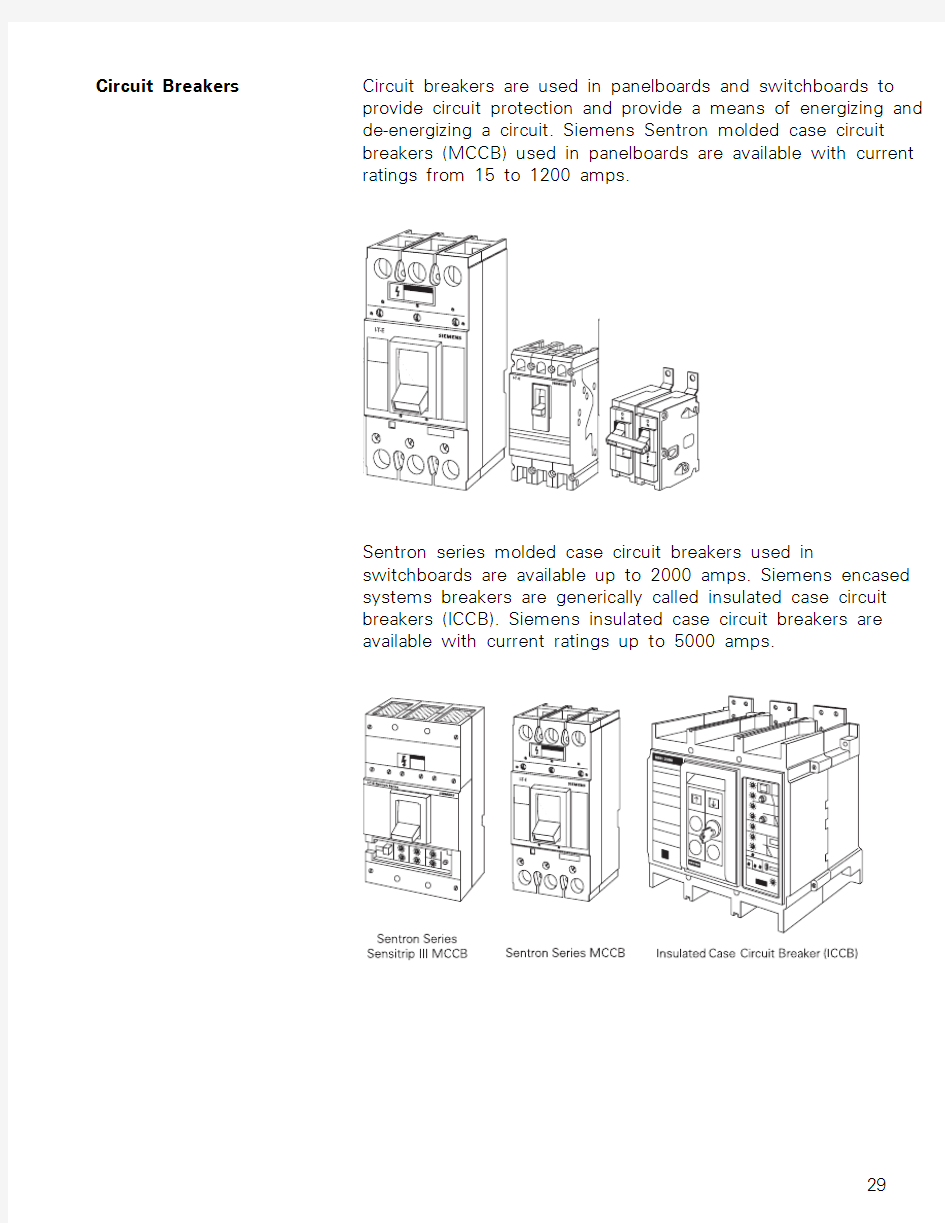
Circuit Breakers Circuit breakers are used in panelboards and switchboards to
provide circuit protection and provide a means of energizing and
de-energizing a circuit. Siemens Sentron molded case circuit
breakers (MCCB) used in panelboards are available with current
ratings from 15 to 1200 amps.
Sentron series molded case circuit breakers used in
switchboards are available up to 2000 amps. Siemens encased
systems breakers are generically called insulated case circuit
breakers (ICCB). Siemens insulated case circuit breakers are
available with current ratings up to 5000 amps.
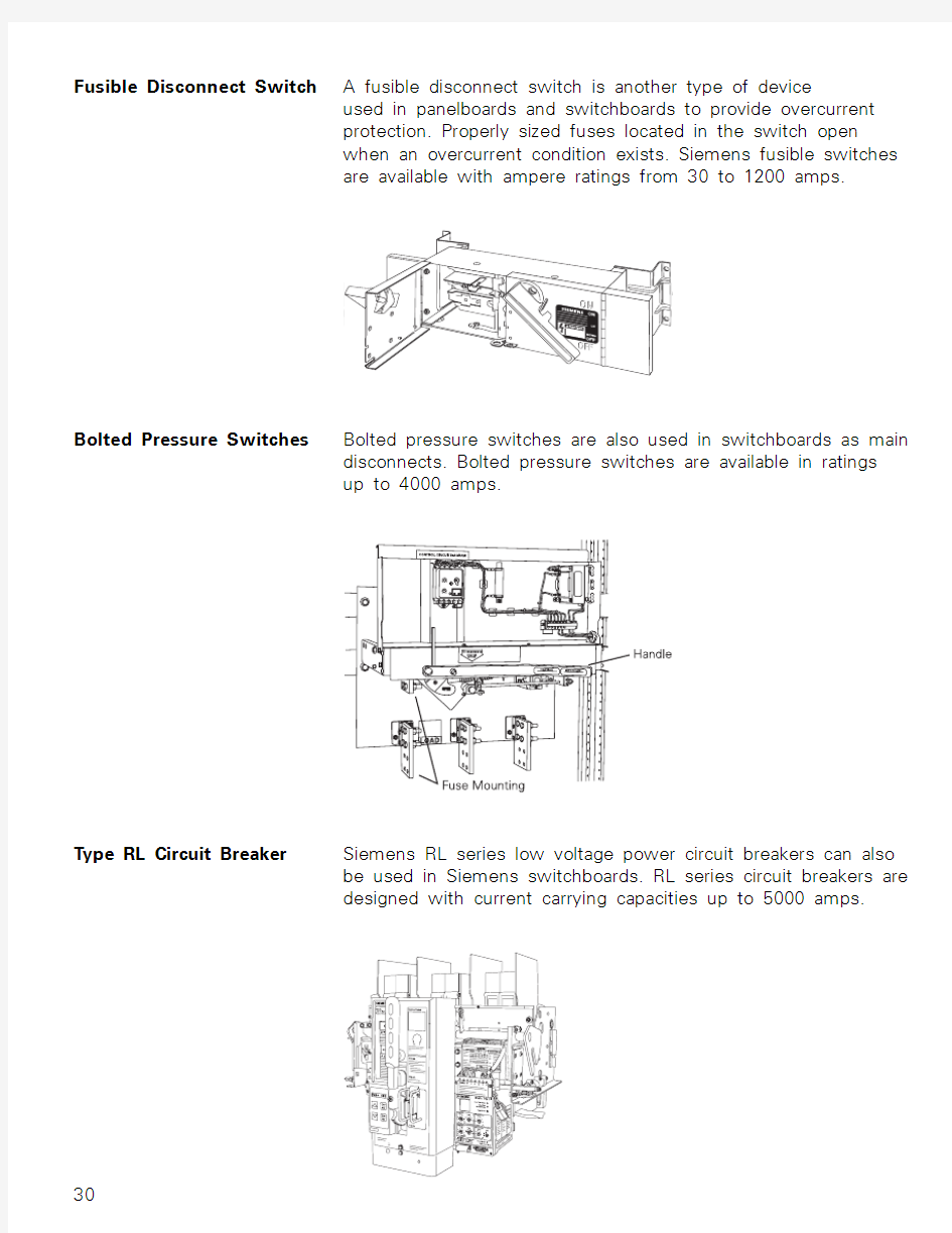
Fusible Disconnect Switch A fusible disconnect switch is another type of device
used in panelboards and switchboards to provide overcurrent
protection. Properly sized fuses located in the switch open
when an overcurrent condition exists. Siemens fusible switches
are available with ampere ratings from 30 to 1200 amps.
Bolted Pressure Switches Bolted pressure switches are also used in switchboards as main
disconnects. Bolted pressure switches are available in ratings
up to 4000 amps.
T ype RL Circuit Breaker Siemens RL series low voltage power circuit breakers can also
be used in Siemens switchboards. RL series circuit breakers are
designed with current carrying capacities up to 5000 amps.
Meters Siemens offers a full line of power meters for use in the service
section of switchboards. Meters can be used to measure
real-time RMS (root-mean-square) values of phase currents,
phase and line voltages, power usage, power factor, and
peak demand. In addition, Siemens also has meters capable
of monitoring power quality, such as K-factor, crest factor,
individual harmonics, and total harmonics. Meters such as the
9350 and 9600 can act as a Web server. When combined with
an Ethernet port, these meters offer quick and easy access to
monitored values without the need for special software.
ACCESS?Siemens meters have communication capability using the
Siemens ACCESS system software. Siemens ACCESS is more
than just power meters and other hardware. The ACCESS
power management and control system is a networked system
comprised of a variety of devices that monitor and control
an electrical distribution system. The ACCESS system provides
electrical data necessary for troubleshooting, power quality
studies, preventative maintenance, and cost allocation. A
power monitoring and management system, such as Siemens
ACCESS, can identify potential problems before they cause
costly breakdowns.
Here are just five benefits to using the ACCESS system.
? Reduce or eliminate unplanned outages
? Proactively manage power systems to minimize utility bills
? Automate allocation of utility power bills
? Optimize existing capital equipment used in power systems
? Record and analyze power quality and power system
anomalies
TPS Computers and other office equipment are susceptible to the
high energy levels caused by an electrical surge, whether it is
caused by electrical equipment or lightning. Any component
between the source of the surge and ground can be damaged.
One option available to protect equipment from electrical
surges is the Siemens TPS (transient protection system). The
TPS clamps voltage spikes before they damage expensive and
sensitive equipment. Siemens TPS can be used with busway,
panelboards, and switchboards.
AC Motors AC motors, such as the Siemens Medallion? motors,
can be found in a variety of applications in commercial
buildings. Siemens Medallion EPACT efficiency motors are high
performance motors designed to meet the requirements of the
U.S. Energy Policy Act of 1992 (EPAct). EPACT efficiency motors
are available from 1 to 200 HP.
Siemens Medallion PE-21 Plus motors are premium efficiency
motors available from 1 to 500 HP. Premium efficiency motors
typically cost slightly more than standard efficiency motors, but
payback is in energy savings.
Motors can be found on fans, pumps, elevators, escalators,
and conveyors. A small conveyor, for example, might be used
in a department store to move packages from a storeroom to a
customer pickup location.
Safety Switches Safety switches provide a means for a service entrance or
a disconnecting means and fault protection for motors. A
safety switch is simply a switch located in its own enclosure.
The enclosure provides a degree of protection to personnel
against incidental contact with live electrical equipment. Safety
switches are available with or without provisions for fuses.
Siemens enclosed switches are available with current ratings
from 30 amps to 4000 amps.
Motor Starter Although safety switches can be used to start and stop
motors, many motor applications require the use of remote
control devices to start and stop the motor. Motor starters are
commonly used to provide this function. Some motor starters
have multi-speed and reversing capability.
A motor starter consists of a magnetic contactor and an
overload relay. The contactor is an electromagnetic device used
to close and open a set of contacts, which starts and stops
the connected motor. If an overload occurs, excessive heat can
build up in a motor which can damage the motor’s winding
insulation. The overload relay will automatically stop the motor
in this event.
Siemens manufactures a variety of starters, such as the Furnas
INNOVA PLUS and the Furnas ESP100.
Review 2
Industrial Applications
Voltage Classes Electrical power requirement is a major consideration in
industrial applications. T ypically voltage is received and
distributed at much higher levels than residential and
commercial applications. Equipment must be specially designed
to receive high transmission voltage from a utility company,
and effectively distribute it throughout the industrial facility.
Industrial facilities typically make large demands on the
electrical utility, making it impractical to supply voltage at lower
levels. The level of voltage supplied by the utility company varies
with the requirements of the facility. For discussion purposes,
it is sometimes convenient to divide voltages into classes.
The Institute of Electrical and Electronics Engineers (IEEE), for
example, divides voltage systems into the following classes:
Since the voltages supplied to the industrial facilities are
typically either low or medium voltages, this discussion will
focus on low and medium voltage systems beginning with a
discussion of switchgear.
Switchgear The term switchgear is used to describe coordinated
devices used for control and protection of equipment such
as generators, transformers, capacitor banks, motors, and
distribution lines. Switchgear is accessible from the front and
rear. Siemens manufactures switchgear for low- and medium-
voltage applications.
Medium-Voltage Medium-voltage switchgear normally conforms to design Switchgear requirements for metal-clad switchgear. Siemens manufactures
medium-voltage switchgear rated at various levels to meet the
requirements of typical medium-voltage applications found in
many industrial facilities.
38 kV Switchgear Siemens 38 kV medium-voltage, metal-clad switchgear is rated
for voltages between 16.5 kV (16,000 volts) and 38 kV (38,000
volts). Siemens metal-clad switchgear features 38-3AF circuit
breakers which are available in 1200, 2000, and 3000 amp
current ratings.
5 - 15 kV Switchgear Siemens 5 - 15 kV metal-clad switchgear is designed to handle
voltages of 4.16 kV (4160 volts), 7.2 kV (7200 volts), and 13.8 kV
(13,800 volts). Siemens 5 - 15 kV switchgear features vacuum
circuit breakers rated for 1200, 2000, and 3000 amps.
NXAIR P NXAIR P medium voltage switchgear is “arc vented”.This
design handles arc fault events more safely by directing
expanding gases of an arc fault up and away from the operator.
NXAIR P meets American standards (ANSI) and international
standards (IEC) for global compliance. NXAIR P handles
voltages from 5 kV to 15 kV with vacuum type circuit breakers
rated from 1200 amps to 4000 amps.
Medium-Voltage A large industrial facility, such as a paper or steel mill, receives Switchgear Example electrical power at a substation from the utility company at high
transmission voltage levels. The voltage is stepped down to a
medium-voltage level at the substation for distribution by the
industrial facility. Large industrial facilities can be spread out
over several acres and incorporate many large buildings. Exact
power distribution will depend on machinery location and power
requirements. Multiple medium-voltage, metal-clad switchgear
units could be used if the facility and the power demand were
large enough.
It can be seen in this example that one 38 kV metal-clad
switchgear unit is supplying power to two 5 kV metal-clad
switchgear units and one 15 kV metal-clad switchgear unit.
This is one way power might be distributed throughout a large
industrial complex made up of several buildings, each requiring
great amounts of electrical power.
Low-Voltage Switchgear Low-voltage switchgear normally conforms to the design
requirements for metal-enclosed switchgear. Siemens low-
voltage switchgear can be used on distribution systems with
208, 240, 480, or 600 volts with currents up to 5000 amps in
the T ype R (indoor) and 4000 amps in the T ype SR (outdoor). TPS
(transient protection system) is available for T ype R, low voltage
switchgear applications.
T ype RL Circuit Breaker Siemens RL series low voltage power circuit breakers are
used in the Siemens low voltage switchgear. RL series circuit
breakers are designed for up to 600-volt service with current
carrying capacities up to 5000 amps.
Secondary Unit Substation Another method used to handle distribution voltage is with a
secondary unit substation.
A typical secondary unit substation consists of three sections
which are coordinated in design to form one uniform enclosure.
1.An incoming section that accepts incoming voltage and
may include a primary switch.
2. A transformer section that transforms incoming voltage
down to a utilization voltage.
3. An outgoing section that distributes power to outgoing
feeders and provides protection for these feeders.
A primary switch is used to provide a means to connect
and disconnect the secondary unit substation from the supply
service. The transformer section can be liquid filled, ventilated
dry type, or a cast-coil type. The outgoing section can be a
Siemens Sentron switchboard, such as the RCIII, or T ype R low-
voltage switchgear.
to the one shown below. In this example, transmission voltage is stepped down to 15 kV and applied to the input of the facility’s secondary unit substation. The transformer located in the substation steps the voltage down to 480 volts where it is distributed to various switchboards and panelboards.
similar to the one shown below. In this application power is received at the industrial facility’s substation where it is stepped down to 38 kV for distribution. The distribution voltage is applied to the input of a 38 kV medium-voltage, metal-clad switchgear unit. One distribution branch is stepped down to 15 kV and applied to the input of a 15 kV switchgear unit. One of the outputs of the 15 kV switchgear is applied to the input of a secondary unit substation which uses low-voltage switchgear to distribute 480 volts throughout one section of the facility. The other outputs of the various switchgear units can be used to similarly distribute power.
Busway Even in large industrial facilities supply voltage must be reduced
to a level that can be used by most electrical equipment.
AC motors, drives, and motor control centers, for example,
typically operate on 480 volts. General lighting and electrical
receptacles operate on 120 volts. Busway is widely used in
industrial applications to distribute this electrical power.
T ypes of Busway Feeder busway is used to distribute power to loads that
are concentrated in one physical area. Industrial applications
frequently involve long runs from the power source to a
single load. This load may be a large machine, motor control
center, panelboard, or switchboard. Feeder busway sections are
available in 0.125” increments from 2’ to 10’.
Plug-in busway is used in applications where power
requirements are distributed over a large area. Using plug-in
units, load connections can be added or relocated easily.
Sentron? plug-in busway is available in 4’, 6’, 8’, and 10’ lengths.
Busway runs also include a number of components such as
tees, offsets, and elbows used to route busway through the
facility.
Busway Example In this example, busway is used to transfer power from
switchgear located outside a building to a switchboard located
inside a building. Electrical power is then distributed to various
locations in the industrial facility. Siemens Sentron busway is
available with current ratings up to 5000 amps at 600 volts.
Review 3
江西省南昌市2015-2016学年度第一学期期末试卷 (江西师大附中使用)高三理科数学分析 一、整体解读 试卷紧扣教材和考试说明,从考生熟悉的基础知识入手,多角度、多层次地考查了学生的数学理性思维能力及对数学本质的理解能力,立足基础,先易后难,难易适中,强调应用,不偏不怪,达到了“考基础、考能力、考素质”的目标。试卷所涉及的知识内容都在考试大纲的范围内,几乎覆盖了高中所学知识的全部重要内容,体现了“重点知识重点考查”的原则。 1.回归教材,注重基础 试卷遵循了考查基础知识为主体的原则,尤其是考试说明中的大部分知识点均有涉及,其中应用题与抗战胜利70周年为背景,把爱国主义教育渗透到试题当中,使学生感受到了数学的育才价值,所有这些题目的设计都回归教材和中学教学实际,操作性强。 2.适当设置题目难度与区分度 选择题第12题和填空题第16题以及解答题的第21题,都是综合性问题,难度较大,学生不仅要有较强的分析问题和解决问题的能力,以及扎实深厚的数学基本功,而且还要掌握必须的数学思想与方法,否则在有限的时间内,很难完成。 3.布局合理,考查全面,着重数学方法和数学思想的考察 在选择题,填空题,解答题和三选一问题中,试卷均对高中数学中的重点内容进行了反复考查。包括函数,三角函数,数列、立体几何、概率统计、解析几何、导数等几大版块问题。这些问题都是以知识为载体,立意于能力,让数学思想方法和数学思维方式贯穿于整个试题的解答过程之中。 二、亮点试题分析 1.【试卷原题】11.已知,,A B C 是单位圆上互不相同的三点,且满足AB AC → → =,则A BA C →→ ?的最小值为( ) A .1 4- B .12- C .34- D .1-
LOGO!Learn Advanced Introduction The LOGO!Learn – Advanced Training Kit is specially designed to match the features of the new LOGO! 0BA6 generation. It is mounted on a stable aluminum base. Eight push/latch buttons (4 of which are debounced) are available for signal inputs as well as 4 potentiometers for voltage setting (0 to 10 V) for analog value inputs. The signal output (status) is indicated by 4 LEDs (5 mm). In addition, you can connect external simulators (e.g., motor controller, traffic light, etc.) via a 24-pin interface plug connector. Four sliding switches on the board switch the digital inputs (I1, I2, I7 and I8) to analog inputs. The "IR receiver" sliding switch switches input I3 to IR receiving. This allows you to implement 10 different switching states on the LOGO! via the IR remote control. The "proximity simulation" sliding switch activates input I4. This allows a frequency of 60 Hz to 5 KHz to be linearly set via the potentiometer and fed to the LOGO! for internal processing. When the "signal encoder on/off" sliding switch is switched on or off, the acoustic signal encoder (i.e., buzzer/beeper) is also switched on or off as necessary. Expansion modules (e.g., Pt100 module, etc.) can be plugged into the LOGO! Learn Advanced and mechanically locked via the 8-pin socket strip. The LOGO! TD can be connected to the "Display" terminal. The small LOGO! controller (version: 0BA6) is mounted on the training PCB in accordance with industrial standards. It can be installed or removed at all times with a screwdriver.
《可编程控制器技术》课程标准 一、课程基本信息 1、课程名称:可编程控制器应用技术 2、适用专业:机电技术应用 3、适用学制:三年制 4、课程学时:120 二、课程性质与作用 本课程是理论+实践课,它是机电技术应用专业的一门专业核心课程。它的任务是培养学生掌握可编程控制器的工作过程及其主要参数,掌握可编程控制器使用方法及电气控制系统设计方法,了解可编程控制系统应用范围和应用环境等。使学生具备从事工业电气控制工作所必需的PLC可编程控制器应用技术的基本知识及应用能力。 本课程根据电气自动化生产企业中可编程控制系统生产实际,设计教学情境,通过相应的教学载体,采用“教、学、做”一体化式教学方式组织教学,培养学生掌握可编程控制器技术的基本知识和基本技能,锻炼学生的可编程控制器技术的基本应用能力;使学生能够在生产现场进行简单的程序设计,能够完成控制系统电气设备安装、调试、运行、检修、维护等实践操作,初步形成解决生产现场实际问题的应用能力;培养学生能动脑会思考的思维能力和一丝不苟、踏实严谨的科学精神,培养学生探索新知识和新技术的学习能力;提高学生爱岗敬业、
团结友爱的综合素质和积极动脑、开拓进取的创新意识。 三、学习领域(课程)目标 (一)知识目标 1、掌握可编程控制器的概念、基本原理,了解其发展状况、分类、作用、应用领域等。 2、掌握可编程控制系统的基本组成和硬件配置。 3、掌握西门子S7-200系列PLC硬件系统安装、检修、维护方法。 4、掌握西门子S7-200系列PLC编程软件STEP7Micro/Win32的使用方法。 5、学会使用S7-200系列PLC进行程序的设计、编写、下载、调试和运行。 6、学会使用S7-200系列PLC控制三相异步电动机启动、正反转、停止等。 7、学会使用S7-200系列PLC对电气典型工程案例的控制方法。 8、学会S7-200系列PLC的主从站通信方法。 9、学会使用组态软件MCGS实时监控PLC电气系统运行。(二)能力目标 1、专业能力 (1)能够正确安装可编程控制器,正确完成硬件接线。 (2)能够编制、调试、运行程序并掌握S7-200系列编程软件的使用。
第一章 S7-300/400的基本结构 1、 S7-300/400属于模块式PLC,主要由机架、CPU模块、信号模块、功能模块、接口模块、通信处理器、电源模块和编程设备(工程师、操作员站和操作屏)组成。 图1-1 PLC控制系统示意图 PLC的主要生产厂家:德国的西门子(Siemens)公司,美国Rockwell公司所属的AB公司,GE-Fanuc公司,法国的施耐德(Schneider)公司,日本的三菱和欧姆龙(OMRON)公司。PLC的工作过程 表1-1 逻辑运算关系表 与或非 Q4.0=I0.0*I0.1 Q4.1 = I0.2+I0.3 Q4.2 =/I0.4 I0.0 I0.1 Q4.0 I0.2 I0.3 Q4.1 I0.4 Q4.2 0 0 0 0 0 0 0 1 0 1 0 0 1 1 1 0 1 0 0 1 0 1 1 1 1 1 1 1 在CPU模块上有存储器(用来存放系统程序、用户程序、逻辑变量和其它一些信息),包括ROM和RAM。可通过扩展槽扩展用户RAM。 l RAM:主程序区OB1+子程序区(FB、FCB、定时中断块等)断电时由锂电池供电(几年)以免RAM中信息丢失。锂电池电压< 规定值,灯报警,换电池(期间靠电容充电几分钟)。 l PLC采用循环执行用户程序的方式。 OB1是用于循环处理的组织块(主程序),它可以调用别的逻辑块,或被中断程序(组织块)中断。在起动完成后,不断地循环调用OB1,在OB1中可以调用其它逻辑块(FB, SFB, FC 或SFC)。 循环程序处理过程可以被某些事件中断。 在循环程序处理过程中,CPU并不直接访问I/O模块中的输入地址区和输出地址区,而是访问CPU内部的输入/输出过程映像区。批量输入、批量输出。 梯形图中Q4.0的线圈(称为内部线圈)“通电”时,对应的输出过程映像位为1状态。信号经输出模块隔离和功率放大后,继电器型输出模块中对应的硬件继电器的线圈(外部线圈)通电,其常开触点闭合,使外部负载通电工作。 外部输入电路接通时,对应的输入过程映像位(例如I0.0)为1状态,梯形图中对应的输入位的常开触点接通,常闭触点断开。 某一编程元件对应的过程映像位为1状态时,称该编程元件为ON,过程映像位为0状态时,称该编程元件为OFF。 循环时间(Cycle time): 是指操作系统执行一次图1-4所示的循环操作所需的时间,又称为扫描循环时间(Scan Cycle Time)或扫描周期。如0.7ms、1.7ms等 l 性能指标: I/O点数、扫描周期、指令数目、功能模块多少、