
LOGO!Learn Advanced
Introduction
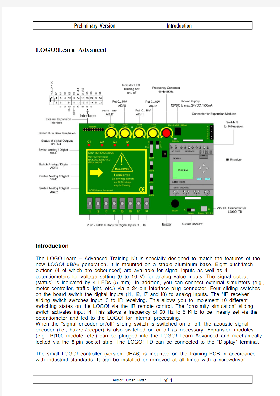
The LOGO!Learn – Advanced Training Kit is specially designed to match the features of the new LOGO! 0BA6 generation. It is mounted on a stable aluminum base. Eight push/latch buttons (4 of which are debounced) are available for signal inputs as well as 4 potentiometers for voltage setting (0 to 10 V) for analog value inputs. The signal output (status) is indicated by 4 LEDs (5 mm). In addition, you can connect external simulators (e.g., motor controller, traffic light, etc.) via a 24-pin interface plug connector. Four sliding switches on the board switch the digital inputs (I1, I2, I7 and I8) to analog inputs. The "IR receiver" sliding switch switches input I3 to IR receiving. This allows you to implement 10 different switching states on the LOGO! via the IR remote control. The "proximity simulation" sliding switch activates input I4. This allows a frequency of 60 Hz to 5 KHz to be linearly set via the potentiometer and fed to the LOGO! for internal processing.
When the "signal encoder on/off" sliding switch is switched on or off, the acoustic signal encoder (i.e., buzzer/beeper) is also switched on or off as necessary. Expansion modules (e.g., Pt100 module, etc.) can be plugged into the LOGO! Learn Advanced and mechanically locked via the 8-pin socket strip. The LOGO! TD can be connected to the "Display" terminal. The small LOGO! controller (version: 0BA6) is mounted on the training PCB in accordance with industrial standards. It can be installed or removed at all times with a screwdriver.
The exercises sequences are arranged from "beginner to advanced" and are printed on 32 learning cards which can be easily rearranged as necessary.
Technical data:
Operating voltage 12 to 24 V DC (max. 24 V) 500 mA
4 each Potentiometers for voltage setting from 0 to 10 V/10 mA
input)
(analog
value
1 each Potentiometer for sonar-proximity simulation from 60 Hz to 5 KHz
1 each IR receiver for receiving 10 selected frequencies via remote control
(an additional 10 inputs on the LOGO!)
8 each Push/latch buttons (4 of which are bounce-free) for signal input
4 each LEDs for the outputs (status indication)
4 each Sliding switches for switching from digital to analog
1 each Sliding switch for switching from digital to IR receiving
1 each Sliding switch for switching from digital to sonar-proximity simulation
1 each Switch for activating the horn (acoustic signal encoder)
1 each Terminal for connection of the LOGO! TD text display
1 each Interface plug connector for connection of models
1 each Socket for expansion modules (8-pin)
Dimensions (W x H x D) 215 x 145 x 100 mm
Weight Approx. 0,73 Kg
CE certification as per EN61000-6-2 and EN61000-6-3
Utility model protection
32 learning cards (practical examples with solutions) are provided:
1. AND
2. OR
3. NOT
4. NAND
5. NOR
6. XOR
7. AND before OR combination
8. Alternating circuit (2-way lighting circuit)
9. 3-way circuit
10. Pulse relay
11. Stairway lighting switch
12. Switch-on delay
13. Switch-off delay
14. Selection circuit 1 of 3
15. Selection circuit 2 of 3
16. Pulse circuit with contactor
17. Garage lighting
18. Mixing plant
19. Gear wheel lubrication
20. Press
21. Lifting platform
22. Automatic Star-Delta-Circuit
23. Rope light
24. Counting of bottles
25. Wind turbine
26. Sequential circuit with time delayed cut-off
27. Parking bay monitoring in a parkade
28. Monitoring of a staff exit
29. Monitoring of a ship with Diesel engine
30. Boiler heating with solar collector
31. Monitoring of temperature in a vessel
32. Temperature indicator with pilot lamps
33. Rolling gat with IR-remote control
34. Floodligt
The package consists of the following:
1 LOGO!Learn – Advanced Training Kit with control unit LOGO! 12/24 RC 1 Mains adapter 230V AC / 24V DC 500mA
34 Learning cards (practical examples) with solutions on a CD-ROM
Attention:
?Only an operating voltage of 12/24V DC should be connected to LOGO! Learn Advanced
?If the inputs I1, I2, I7 or I8 are used for analog signals, the related sliding switches AI1 to AI4 have to be switched to position “A” (analog) otherwise
they must be in “D” position for “digital”. If the analog inputs are used (switch in “analog” position) the related digital inputs will be inactive and the analog
inputs will be switched to active. The potentiometers A1 to A4 can then be
used.
?External inputs and outputs can be added via the interface connector.
?Please note that 24V DC should not be exceeded on the external interface connector. Any excess voltage will damage the device. If external analog
signals 0-10V DC are fed into the LOGO! (I1, I2, I7 or I8), the sliding switches have to be set to “digital“. In that case no switches on the board (switches 1-8) should be activated (all switches to be set to “0” in the middle position) ?Inputs I3 to I6 can be used for fast counting inputs (up to 5 KHz). It is thus possible to determine, for example, the exact position of an object on a
conveyor belt
Models of conveyor belts for this application are available from IKH - Didaktische Systeme.
Please ask for our general catalogue on a CD or on paper.
Suggestions are always welcome.
LOGO!Learn Basis
Introduction
The LOGO!Learn – Basic training kit is mounted on a sturdy aluminium frame.
For the signal inputs there are 8 push-button/switches provided as well as 2 potentiometers for analog inputs. Furthermore, it is possible to connect external simulators via the 14-pin interface-connector. The signal output (state) is indicated by 4 Light Emitting Diodes (LED 5mm). Two sliding switches on the board enable the switch-over from digital inputs (I7+I8) to analog inputs (0…10V). The exercises are based on the principle of increasing difficulty and are printed on 32 learning cards. These cards are interchangeable as required.
32 learning cards (practical examples with solutions) are provided:
1. AND
2. OR
3. NOT
4. NAND
5. NOR
6. XOR
7. AND before OR combination
8. Alternating circuit (2-way light circuit)
9. 3-way circuit
10. Pulse relay
11. Stairway lighting switch
12. Switch-on delay
13. Switch-off delay
14. Selection circuit 1 of 3
15. Selection circuit 2 of 3
16. Pulse circuit with contactor
17. Garage lighting
18. Mixing plant
19. Gear wheel lubrication
20. Press
21. Lifting platform
22. Automatic Star-Delta-Circuit
23. Rope light
24. Counting of bottles
25. Wind turbine
26. Sequential circuit with time delayed cut-off
27. Parking bay monitoring in a parkade
28. Monitoring of a staff exit
29. Monitoring of a ship with Diesel engine
30. Boiler heating with solar collector
31. Monitoring of temperature in a vessel
32. Temperature indicator with pilot lamps
The package consists of the following:
1 LOGO!Learn - BasicTraining Kit with control unit LOGO! 12/24 RC
1 Mains adapter 230V AC / 12V DC 500 mA
32 Learning cards (practical examples) with solutions on a CD-ROM
Attention:
?Only an operating voltage of 12V DC should be connected to LOGO!Learn - Basic
?If all 8 inputs are used, the sliding switches I7 and I8 have to be switched to the “digital” position. If the analog inputs I7 or I8 are used (“analog” switch
position) the digital inputs 7 or 8 will be inactive and the analog inputs will be switched to active. The potentiometers A1 and A2 respectively can then be
used.
?External inputs and outputs can be added via the interface connector.
?Please note that 12V DC should not be exceeded on the interface connector.
Any excess voltage will ruin the instrument. If external analog signals 0-10V
DC are fed into the instrument (I7 or I8) via the external interface, the sliding
switches have to be set to “digital”. In this case, the switches on the board
(switches 1-8) should be deactivated (all switches to be set to “0”)
Inputs I5 and I6 can be used for fast counting inputs (up to 2 KHz) for the LOGO! versions -0BA5. It is thus possible to determine, for example, the exact position of an object on a conveyor belt.
Models of conveyor belts for this application are available from IKH - Didaktische Systeme.
Please ask for our general catalogue on a CD or on paper.
Suggestions are always welcome.
Version: 18.08.2008
Page 1 of 9
.
.
Version: 18.08.2008
Page 2 of 9
.
.
Version: 18.08.2008
Page 3 of 9
.
.
Version: 18.08.2008
Page 4 of 9
.
.
Version: 18.08.2008
Page 5 of 9
.
.
Version: 18.08.2008
Page 6 of 9
.
.
Version: 18.08.2008
Page 7 of 9
.
.
Version: 18.08.2008
Page 8 of 9
.
.
Version: 18.08.2008
Page 9 of 9
.
.
江西省南昌市2015-2016学年度第一学期期末试卷 (江西师大附中使用)高三理科数学分析 一、整体解读 试卷紧扣教材和考试说明,从考生熟悉的基础知识入手,多角度、多层次地考查了学生的数学理性思维能力及对数学本质的理解能力,立足基础,先易后难,难易适中,强调应用,不偏不怪,达到了“考基础、考能力、考素质”的目标。试卷所涉及的知识内容都在考试大纲的范围内,几乎覆盖了高中所学知识的全部重要内容,体现了“重点知识重点考查”的原则。 1.回归教材,注重基础 试卷遵循了考查基础知识为主体的原则,尤其是考试说明中的大部分知识点均有涉及,其中应用题与抗战胜利70周年为背景,把爱国主义教育渗透到试题当中,使学生感受到了数学的育才价值,所有这些题目的设计都回归教材和中学教学实际,操作性强。 2.适当设置题目难度与区分度 选择题第12题和填空题第16题以及解答题的第21题,都是综合性问题,难度较大,学生不仅要有较强的分析问题和解决问题的能力,以及扎实深厚的数学基本功,而且还要掌握必须的数学思想与方法,否则在有限的时间内,很难完成。 3.布局合理,考查全面,着重数学方法和数学思想的考察 在选择题,填空题,解答题和三选一问题中,试卷均对高中数学中的重点内容进行了反复考查。包括函数,三角函数,数列、立体几何、概率统计、解析几何、导数等几大版块问题。这些问题都是以知识为载体,立意于能力,让数学思想方法和数学思维方式贯穿于整个试题的解答过程之中。 二、亮点试题分析 1.【试卷原题】11.已知,,A B C 是单位圆上互不相同的三点,且满足AB AC → → =,则A BA C →→ ?的最小值为( ) A .1 4- B .12- C .34- D .1-
LOGO!Learn Advanced Introduction The LOGO!Learn – Advanced Training Kit is specially designed to match the features of the new LOGO! 0BA6 generation. It is mounted on a stable aluminum base. Eight push/latch buttons (4 of which are debounced) are available for signal inputs as well as 4 potentiometers for voltage setting (0 to 10 V) for analog value inputs. The signal output (status) is indicated by 4 LEDs (5 mm). In addition, you can connect external simulators (e.g., motor controller, traffic light, etc.) via a 24-pin interface plug connector. Four sliding switches on the board switch the digital inputs (I1, I2, I7 and I8) to analog inputs. The "IR receiver" sliding switch switches input I3 to IR receiving. This allows you to implement 10 different switching states on the LOGO! via the IR remote control. The "proximity simulation" sliding switch activates input I4. This allows a frequency of 60 Hz to 5 KHz to be linearly set via the potentiometer and fed to the LOGO! for internal processing. When the "signal encoder on/off" sliding switch is switched on or off, the acoustic signal encoder (i.e., buzzer/beeper) is also switched on or off as necessary. Expansion modules (e.g., Pt100 module, etc.) can be plugged into the LOGO! Learn Advanced and mechanically locked via the 8-pin socket strip. The LOGO! TD can be connected to the "Display" terminal. The small LOGO! controller (version: 0BA6) is mounted on the training PCB in accordance with industrial standards. It can be installed or removed at all times with a screwdriver.
《可编程控制器技术》课程标准 一、课程基本信息 1、课程名称:可编程控制器应用技术 2、适用专业:机电技术应用 3、适用学制:三年制 4、课程学时:120 二、课程性质与作用 本课程是理论+实践课,它是机电技术应用专业的一门专业核心课程。它的任务是培养学生掌握可编程控制器的工作过程及其主要参数,掌握可编程控制器使用方法及电气控制系统设计方法,了解可编程控制系统应用范围和应用环境等。使学生具备从事工业电气控制工作所必需的PLC可编程控制器应用技术的基本知识及应用能力。 本课程根据电气自动化生产企业中可编程控制系统生产实际,设计教学情境,通过相应的教学载体,采用“教、学、做”一体化式教学方式组织教学,培养学生掌握可编程控制器技术的基本知识和基本技能,锻炼学生的可编程控制器技术的基本应用能力;使学生能够在生产现场进行简单的程序设计,能够完成控制系统电气设备安装、调试、运行、检修、维护等实践操作,初步形成解决生产现场实际问题的应用能力;培养学生能动脑会思考的思维能力和一丝不苟、踏实严谨的科学精神,培养学生探索新知识和新技术的学习能力;提高学生爱岗敬业、
团结友爱的综合素质和积极动脑、开拓进取的创新意识。 三、学习领域(课程)目标 (一)知识目标 1、掌握可编程控制器的概念、基本原理,了解其发展状况、分类、作用、应用领域等。 2、掌握可编程控制系统的基本组成和硬件配置。 3、掌握西门子S7-200系列PLC硬件系统安装、检修、维护方法。 4、掌握西门子S7-200系列PLC编程软件STEP7Micro/Win32的使用方法。 5、学会使用S7-200系列PLC进行程序的设计、编写、下载、调试和运行。 6、学会使用S7-200系列PLC控制三相异步电动机启动、正反转、停止等。 7、学会使用S7-200系列PLC对电气典型工程案例的控制方法。 8、学会S7-200系列PLC的主从站通信方法。 9、学会使用组态软件MCGS实时监控PLC电气系统运行。(二)能力目标 1、专业能力 (1)能够正确安装可编程控制器,正确完成硬件接线。 (2)能够编制、调试、运行程序并掌握S7-200系列编程软件的使用。
第一章 S7-300/400的基本结构 1、 S7-300/400属于模块式PLC,主要由机架、CPU模块、信号模块、功能模块、接口模块、通信处理器、电源模块和编程设备(工程师、操作员站和操作屏)组成。 图1-1 PLC控制系统示意图 PLC的主要生产厂家:德国的西门子(Siemens)公司,美国Rockwell公司所属的AB公司,GE-Fanuc公司,法国的施耐德(Schneider)公司,日本的三菱和欧姆龙(OMRON)公司。PLC的工作过程 表1-1 逻辑运算关系表 与或非 Q4.0=I0.0*I0.1 Q4.1 = I0.2+I0.3 Q4.2 =/I0.4 I0.0 I0.1 Q4.0 I0.2 I0.3 Q4.1 I0.4 Q4.2 0 0 0 0 0 0 0 1 0 1 0 0 1 1 1 0 1 0 0 1 0 1 1 1 1 1 1 1 在CPU模块上有存储器(用来存放系统程序、用户程序、逻辑变量和其它一些信息),包括ROM和RAM。可通过扩展槽扩展用户RAM。 l RAM:主程序区OB1+子程序区(FB、FCB、定时中断块等)断电时由锂电池供电(几年)以免RAM中信息丢失。锂电池电压< 规定值,灯报警,换电池(期间靠电容充电几分钟)。 l PLC采用循环执行用户程序的方式。 OB1是用于循环处理的组织块(主程序),它可以调用别的逻辑块,或被中断程序(组织块)中断。在起动完成后,不断地循环调用OB1,在OB1中可以调用其它逻辑块(FB, SFB, FC 或SFC)。 循环程序处理过程可以被某些事件中断。 在循环程序处理过程中,CPU并不直接访问I/O模块中的输入地址区和输出地址区,而是访问CPU内部的输入/输出过程映像区。批量输入、批量输出。 梯形图中Q4.0的线圈(称为内部线圈)“通电”时,对应的输出过程映像位为1状态。信号经输出模块隔离和功率放大后,继电器型输出模块中对应的硬件继电器的线圈(外部线圈)通电,其常开触点闭合,使外部负载通电工作。 外部输入电路接通时,对应的输入过程映像位(例如I0.0)为1状态,梯形图中对应的输入位的常开触点接通,常闭触点断开。 某一编程元件对应的过程映像位为1状态时,称该编程元件为ON,过程映像位为0状态时,称该编程元件为OFF。 循环时间(Cycle time): 是指操作系统执行一次图1-4所示的循环操作所需的时间,又称为扫描循环时间(Scan Cycle Time)或扫描周期。如0.7ms、1.7ms等 l 性能指标: I/O点数、扫描周期、指令数目、功能模块多少、