遭受腐蚀和疲劳的集装箱船船体梁可靠性
- 格式:pdf
- 大小:204.25 KB
- 文档页数:19
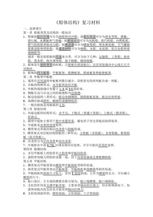
《船体结构》复习材料一、选择填空1璃钢船等。
通常一般是按船舶的用途来分类,可分为如下几种:运输船、工程船、渔业2对称时。
3、船体的四大板架:甲板板架、舷侧板架、船底板架和舱壁板架。
第二章1、通常在首尾端将外板板列数目减少,而把原有的两列板并成一列板。
2、并板的两种形式:双并板和齿形并板。
3、外板的端接缝应布置于1 /4或3/4肋距处。
4、钢板长边与长边之间的接缝称为边接缝:5、舷边连接的三类形式:舷边角钢铆接、圆弧舷板连接、舷边直角焊接。
6、角隅应做成圆形、椭圆形或抛物线形。
7、一般首舷弧是尾舷弧的2倍。
第三章船底结构1、内底边板的结构形式:水平式、下倾式(普通干货船)、上倾式(散货船)、折曲式。
2、箱型中底桁主要用于集中布置管系,避免管子穿过货舱而妨碍装货。
3、中底桁是水密的连续构件。
4、横骨架式单底结构由内龙骨与肋板组成。
5、横骨架式双层底结构肋板的三种形式:主肋板(实肋板)、水密肋板、框架肋板(组合肋板)。
6、内龙骨分为中内龙骨和旁内龙骨。
7、中底桁在中部0.75L区域范围内应连续,并尽可能向首尾柱延伸。
第四章舷侧结构1、多层甲板船上的肋骨有主肋骨和甲板间肋骨。
2、强肋骨每隔几档肋距设置一道,用于局部加强或支撑舷侧纵桁。
第五章甲板结构1、横骨架式甲板骨架由横梁和甲板纵桁等构件组成。
2、纵骨架式甲板骨架由甲板纵骨、甲板纵桁和强横梁等构件组成。
3、甲板纵桁的剖面尺寸较大,常用T型材制成,它作为横梁的支点,可以减小横梁的尺寸。
4、舱口前后、左右端的横梁名称分别为:舱口端横梁,舱口端纵桁。
5、支柱的作用是支撑甲板骨架,主要承受轴向的压缩力,但在特殊情况下,如液体深舱内的支柱也可能受到轴向拉伸力。
6、支柱的剖面形状:圆管剖面,方管剖面,工字型剖面。
7、在多层甲板上,支柱应尽可能设在同一垂线上,使甲板上的载荷通过支柱一直传到船底的刚性物体上。
8、普通横梁与甲板纵桁相遇时,纵桁腹板上开切口让横梁穿过,并且每隔2挡—4挡肋距设置防倾肘板。
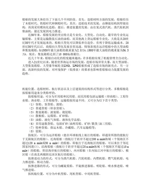
船舶的发展大体经历了下面几个不同阶段。
首先,造船材料方面的发展,船舶经历了木船时代、铁船时代和钢船时代;其次,造船技术的发展,由铆接结构到焊接结构,再到采用模块化造船;最后,推进装置的发展,由往复式蒸汽机、蒸汽轮机到柴油机,最近发展到电力推进。
近50年来,船舶发展的突出特点是专业化、大型化、自动化。
最早的专业化运输船舶,主要是运输散装石油的油船,而其他海上货运船舶专业化,大致是从20世纪50年代才发展起来的。
船舶大型化可以降低单位造价,有利于降低运输成本。
20世纪50年代以后,商船向大型化发展非常迅速,特别表现在远洋船舶中的大型油船和集装箱船,如1950年最大油船的载重量为2.8万t,1980年最大油船的载重量为56.3万t。
现在,集装箱船达到了10 000标准箱位。
近几十年来,船舶自动化的程度越来越高,许多船舶实现了机舱管理全自动化。
进入21世纪以来,随着世界海运市场的发展,造船市场异常火暴,而大型油船、大型集装箱船、大型豪华邮轮及LNG、LPG船舶形成了造船市场的新亮点。
另一方面,高新科技的发展、对环境保护(低排放)的要求也影响着船舶动力装置发展的趋势。
机舱位置、造船材料、航行状态以及上层建筑的结构形式等进行分类。
多数船舶是按船舶用途来分类称呼的。
按船舶用途,可分为军用船和民用船。
而民用船包括运输船(即商船)、工程作业船、渔业船、工作船舶等。
运输船按用途不同,又可分为以下若干类型:(1)客船、客货船、渡船;(2)普通货船(即杂货船);(3)集装箱船、滚装船、载驳船;(4)散粮船、运煤船、矿砂船;(5)油船、液化气体船、液体化学品船;(6)多用途散货船,包括矿砂/油两用船、矿砂/散货/油三用船;(7)特种货船,指运木船、冷藏船、汽车运输船等;(8)驳船。
按航区,可分为远洋船舶(能在环球航线上航行的船舶,即通常所指的能航行于无限航区的船舶)、近海船舶(指航行于距岸不超过200 n mile海域(个别海区不超过120 n mile或50 n mile)的船舶,即航行于近海航区的船舶,可以来往于邻近国家间港口)、沿海船舶(指航行于距岸不超过20 n mile海域(个别海区不超过10 n mile)的船舶,即沿海岸航行的船舶)、内河船舶(在内陆江河中航行的船舶)、极区船(在南北两极附近冰区航行的船舶)。
船体结构习题课第09401014/5/61 目录二、填空(每空 1 分)三、单项选择题(每题 1 分)四、判断题(每题 1 分)五、简答题(每题 4 分)六、论述题(每题10 分)一、名词解释(每题 3 分)舭列板:舭部的列板。
舭龙骨:沿船长方向装设在舭部外侧的条状减摇构件。
船体结构:由板材和骨材等组成的船体结构的统称。
船体中垂弯曲:波谷在船中时,使船体产生的中部向下弯曲船体中拱弯曲:波峰在船中时,使船体产生的中部向上弯曲 3 垂线间长:首、尾垂线之间的水平距离。
横骨架式结构:横向骨材较密、纵向骨材较稀的骨架形式横向强度:指横向构件抵抗横向载荷的能力甲板边板:沿甲板外缘的一列甲板板甲板间肋骨:指两层甲板之间的肋骨4局部强度:指个别构件对局部载荷的抵抗能力内底边板:与外板相连的一列内底板旁底桁:双层底中线面两侧的底纵桁平板龙骨:位于船体中线处的一列船底板强力甲板:船体总纵弯曲时,起最大抵抗作用的甲板5外板:指构成船体底部、舭部及舷侧外壳的板外板边接缝:外板沿船长方向的接缝线外板端接缝:外板横向的接缝舷顶列板:与上甲板连接的舷侧外板中底桁:双层底内中线面处的纵桁6型宽:船体中站面处,左右舷之间的水平距离型深:船体中站面处,船体基线至甲板边线与舷侧外板交线之间的垂直距离中间肋骨:水线附近在两肋骨中间设置的短肋骨中内龙骨:单层船底结构中,中线面处的纵桁纵骨架式结构:板格长边沿船长方向短边沿船宽方向,纵向骨材较密、横向骨材较稀的骨架形式7总纵强度:船体结构抵抗纵向弯曲不使整体结构遭受破坏或不允许变形的能力总纵弯曲:作用在船体上的重力、浮力、波浪水动力和惯性力等而引起的船体绕水平横轴的弯曲称为总纵弯曲横骨架式结构:板格长边沿船宽方向短边沿长宽方向,纵向骨材较稀、横向骨材较密的骨架形式。
舷侧外板:舭列板以上的外板舷弧:上甲板边线沿纵向向首尾端升高的曲线梁拱:上甲板沿横向的拱形。
二、填空(每空 1 分)1、舭龙骨装设在船中部 _________ 至_________ 船长之内。

船舶结构与货运11.在静稳性曲线图上可求得:①极限静倾角;②最小倾覆力矩;③船舶的甲板浸水角A.①B.②C.③D.①②③2.某船在装卸货时,将一票货物进行了横移,移动货物的重量为32t,横移距离为14.6m,船舶当时的排水量为11200t,由横倾仪读得横倾角为2.8°,则船舶的初稳性高度为:A.0.85 B.0.63 C.1.20 D.1.743.船舶总吨位的用途是:A.表明船舶的载重能力B.表明各国造船工业的发展水平和国家的运输力量C.比较船舶大小及计算海损事故赔偿的依据D.港口向船舶收取港口使用费和税金的依据4.配装第4类的固体散货,应:①远离热源、火源;②舱位处于冷却和干燥状态;③船舶电气设备状态良好A.①②B.②③C.①③D.①②③5.重大件货系固时,若货件与甲板间摩擦力较小,需____以防货件水平移动。
①增加其他货物支撑;②增加系锁道术;③加衬垫A.①②B.②③C.①③D.①②③6.危险货物积载中,表示不可在同一舱室配装,但可在相邻舱室配装的称为:A.隔离B. 远离 C .间隔一个舱室 D. 用一个货舱做纵向分隔7.某轮配装一票箱装货,重量为210t,不包括亏舱的积载因数S。
F=1.85m/t,亏舱率估计为8%,问装载该票货物所需舱容____㎡。
、A.421.8 B.424.6 C.390.6 D.407.48.船舶少量装载时,可用____计算吃水改变量。
A.厘米纵倾力矩B.厘米吃水吨数C.初稳性高度D.静稳性力臂9.某轮吃水d=9.0m,水线面面积A=1800平方米,则此时船舶的海水厘米吃水吨数为:A.16.0 B.18.1 C.18.45 D.16.410.船内载荷水平横移对初稳性高度GM的影响是____。
A.不改变GM值的大小,所以不影响船舶稳性B.相当于使船舶重心升高,使GM值减小C.载荷横移后,横稳心距基线高度KM减小,所以GM减小D.载荷横移后,船舶总重心G随之横移,使GM变大11.船尾结构区域要承受的力有:①水压力;②车叶转动的震动力和水动力;③舵的水动力及车叶与舵叶的荷重A.①②B.②③C.①③D.①②③12.油轮在配载时用来保证适宜吃水差的经验方法有____。
集装箱不同部位腐蚀速率差异作者:龚必洪米琳唐荣健来源:《集装箱化》2011年第07期集装箱的使用寿命是有限的,理想情况下各部位的使用寿命应当相同。
然而,在集装箱的使用过程中,有的部位存在早期锈蚀甚至锈穿的情况,需要修补后才能继续使用;而有的部位直到集装箱退役都未修补过,还能继续使用。
由此可见,集装箱各部位的使用寿命差异很大。
本文对集装箱不同部位的腐蚀速率差异进行分析和验证,为改进集装箱涂层方案提供依据。
1不同环境下金属材料腐蚀速率差异不同环境下金属材料的腐蚀速率不同。
为获得全面、系统的腐蚀数据,原国家科学技术委员会和国家自然科学基金委员会组建国家材料环境腐蚀试验站网,在北京、武汉、青岛、重庆、广州、琼海、万宁等地设立暴露站(户外试验基地),自1983年开始分5个周期开展为期20年的数据积累和研究工作。
试验结果表明,不同环境下金属材料的腐蚀速率差异非常大。
梁彩凤等[1]在北京、青岛、万宁等地对碳钢和低合金钢进行为期8年的大气暴露腐蚀试验。
王成章等[2]在万宁离海边不同距离处对Corten A钢和Q235钢进行大气暴露试验。
2集装箱不同部位腐蚀速率差异日晒、雨水、盐分、污染等环境因素对金属材料腐蚀速率的影响很大。
由于集装箱不同部位(外部、底架、内部)所处的环境不同,因此腐蚀速率也不尽相同。
本文将集装箱外部视为户外,底架视为棚下,内部视为库房,对集装箱不同部位的腐蚀速率差异进行分析。
廖国栋等[3]在西沙、海南、广州等3个试验站对钢板进行为期1年半的天然腐蚀试验,结果表明,钢板在户外的腐蚀速率最快,在库房的腐蚀速率最慢(见表1)。
也就是说,集装箱外部腐蚀速率最快,底架次之,内部最慢。
为验证上述结论,对集装箱不同部位的腐蚀情况进行现场调研,结果如下:(1)箱龄10年以上的集装箱外部整面锈蚀甚至锈穿的情况较为普遍;(2)集装箱底架梁下部由于经常与其他物体发生碰撞,通常在使用2~3年后就开始锈蚀,但锈蚀速率很慢,即使箱龄近20年的集装箱也罕有底架锈穿并影响使用的情况;(3)箱体内部总的来说锈蚀较少,即使存在锈蚀,也是由于装运腐蚀性货物或清洗集装箱造成的。
大型集装箱船高强度钢甲板裂纹缺陷的安全寿命评估张鼎;黄小平;丁仕风;洪英;徐博文【摘要】文章根据船级社规范的疲劳校核应力计算方法及应力范围长期分布的基本特征,采用等效应力法将船舶受到的外载荷转换为等幅疲劳载荷。
将失效评估图技术和疲劳裂纹扩展计算方法结合起来,探讨复杂载荷作用下集装箱船高强度钢甲板安全寿命评估方法,并考虑焊接残余应力的影响。
对某大型集装箱船上甲板焊接接头焊趾处裂纹缺陷在复杂载荷作用下的疲劳寿命进行了评估,其中考虑了表面裂纹缺陷和埋藏裂纹缺陷两种情况。
结果表明,初始裂纹的尺寸大小对裂纹扩展影响显著,且在相同的初始裂纹尺寸和外载荷条件下,表面疲劳裂纹对结构安全的危害性比内部的埋藏裂纹危害性更大。
%The fatigue loading is obtained based on the classification society rules and Weibull long-term checking stress range distribution. Equivalent stress method is used to transform random loading spectrum into constant loading spectrum. A procedure which consists of FAD technology and crack growth life pre-diction method is used to assess the security life of high tensile thick steel plates under complex loading conditions. Fatigue life of a surface crack and an embedded crack located at butt welded joint in the upper deck of a large container ship under complex loading conditions, considering the effect of welded residu-al stress, are assessed respectively. It is concluded that the initial size of crack has significant effect on crack growth behavior, and the harmfulness of surface crack on structural security is more serious than that of em-bedded crack in conditions of the same initial crack size and applied load.【期刊名称】《船舶力学》【年(卷),期】2014(000)005【总页数】10页(P540-549)【关键词】高强度厚钢板;失效评估图技术;裂纹缺陷;单一曲线模型;应力范围;寿命评估【作者】张鼎;黄小平;丁仕风;洪英;徐博文【作者单位】上海交通大学海洋工程国家重点实验室,上海 200240; 中国船舶及海洋工程设计研究院,上海 200011;上海交通大学海洋工程国家重点实验室,上海 200240;中国船级社上海规范研究所,上海 200135;中国船级社上海规范研究所,上海 200135;中国船级社上海规范研究所,上海 200135【正文语种】中文【中图分类】U661.4大型集装箱船具有长大开口、方型系数小、剖面变化显著和明显艏外飘以及高航速等特点,为减轻船体自重,上甲板等结构构件大量采用高强度厚钢板,其疲劳问题更为突出需要加以重视。
新型船舶材料的应用与发展趋势在当今全球化的时代,船舶运输在国际贸易和经济发展中扮演着至关重要的角色。
随着科技的不断进步,新型船舶材料的应用正在逐渐改变着船舶制造业的面貌,并为船舶的性能、安全性和环保性带来了显著的提升。
本文将探讨新型船舶材料的应用现状以及未来的发展趋势。
一、新型船舶材料的应用1、高强度钢高强度钢在船舶制造中的应用越来越广泛。
相比传统的钢材,高强度钢具有更高的强度和韧性,能够减轻船舶的自重,提高载货量和航行速度。
例如,在大型集装箱船和油轮的建造中,高强度钢被用于船体结构的关键部位,如船板、船梁和框架等,有效地增强了船舶的整体强度和稳定性。
2、铝合金铝合金因其轻质、耐腐蚀和良好的加工性能,在船舶制造中得到了大量应用。
特别是在高速船舶、游艇和小型工作船中,铝合金被用于制造船体、甲板和上层建筑,减轻了船舶的重量,提高了航行速度和燃油效率。
此外,铝合金还具有良好的导热性能,适用于船舶的散热系统和空调设备。
3、复合材料复合材料,如碳纤维增强复合材料(CFRP)和玻璃纤维增强复合材料(GFRP),在船舶制造中的应用逐渐增加。
复合材料具有高强度、高模量、耐腐蚀和抗疲劳等优点,能够显著减轻船舶的结构重量,提高船舶的性能和耐久性。
在高性能船舶,如赛艇、军舰和豪华游艇中,复合材料被用于制造船体、桅杆和舵叶等部件,提高了船舶的速度和操控性能。
4、钛合金钛合金具有优异的耐腐蚀性、高强度和低密度等特点,在船舶领域的应用主要集中在海洋工程装备和军舰上。
例如,钛合金可用于制造海水淡化装置、冷凝器和潜艇的耐压壳体等部件,能够在恶劣的海洋环境中保持良好的性能。
5、高分子材料高分子材料在船舶上的应用范围也在不断扩大。
例如,聚乙烯、聚丙烯等塑料材料被用于制造船舶的管道、电缆护套和内饰件;橡胶材料被用于制造密封件、减震器和护舷等部件;聚氨脂泡沫材料被用于船舶的保温和隔音。
二、新型船舶材料的发展趋势1、高性能化未来的船舶材料将朝着更高性能的方向发展。
集装箱船舶的结构特点
集装箱船舶是一种专门用于运输集装箱的大型货船,其结构特点主要包括以下几个方面:
1. 大型化:集装箱船舶通常具有较大的吨位和载重能力,可以同时运输大量的集装箱。
这种大型化的特点使得集装箱船舶可以更加高效地运输货物,降低运输成本。
2. 高度标准化:集装箱船舶的货舱通常都是标准化的集装箱尺寸,这种标准化的设计使得货物可以更加方便地装卸和运输,同时也提高了运输效率。
3. 船体结构:集装箱船舶的船体结构通常采用双壳结构,这种结构可以提高船舶的稳定性和安全性,同时也可以减少船舶的维修和保养成本。
4. 船舶设备:集装箱船舶通常配备有先进的船舶设备,如自动化控制系统、船舶通讯设备、导航设备等,这些设备可以提高船舶的运输效率和安全性。
5. 船舶管理:集装箱船舶的管理通常采用现代化的管理模式,如船舶管理信息系统、船舶维修管理系统等,这些管理模式可以提高船舶的管理效率和运输效率。
集装箱船舶的结构特点主要体现在大型化、标准化、船体结构、船
舶设备和船舶管理等方面,这些特点使得集装箱船舶成为现代化海运业中不可或缺的一部分,为全球贸易和经济发展做出了重要贡献。
Reliabilityofmaintainedshiphullgirderssubjectedtocorrosionandfatigue
C.GuedesSoares*,Y.GarbatovUnitofMarineTechnologyandEngineering,InstitutoSuperiorTeÂcnico,Av.RoviscoPais,1096Lisboa,Portugal
AbstractAformulationispresentedtoaccountfortheeectofcorrosionandfatigueonthereliabilityofshiphulls.Atimevariantformulationispresentedinwhichtheeectofthesedegradationphenomenaonthehullsectionmodulusisquanti®ed.Theeectofmaintenanceactionsisaccountedforbyconsideringthattherepairedelementsarerestoredtoastateasnew.Dierentrepairpoliciescanbestudiedandtheapproachcanbeusedasatooltoplanthemaintenanceactionsbasedonreliabilityresults.#1998ElsevierScienceLtd.Allrightsreserved
Keywords:Maintainedshiphullgirders;Corrosion;Fatigue.
1.IntroductionThedegradationoftheshiphullisaresultofthecombinedeectofcorrosionandfatiguecrackgrowth.Thesetwophenomenahavethecommoncharacteristicthattheyareamonotonicfunctionoftimeinducingasystematicdecreaseofstrength.Thispaperconsidersthereliabilityofashiphullgirdersubjectedtothesimultaneousactionofcorrosionandoffatigueinlongitudinalmembers.Theeectofbothphenomenaonthesectionmodulusisaccountedanditisusedasthereferencevariabletomeasurethereliabilityoftheshiphullagainstcollapse.Inresistingthelongitudinalbendingduetowavesandweightdistribution,theshiphullbendsasabeamandassuch,thelevelsofstressesinthedeckandbottomdependonthemomentofinertiaofitscrosssectionwhichisverymuchdependentontheamountofcontinuouslongitudinalmaterialinthedeckandbottom.Thedegradingeectofgeneralcorro-sionisre¯ectedinthedecreasedthicknessoftheplatingwhichinturndecreasesthemomentofinertiaoftheshipcrosssectionandthusinduceshigherstresslevelsforthesameappliedmoments.Theeectofcracksonthelongitudinalstrengthisaccountedinasimilarmanner.Thepropagationofcracksinstienersorintheplatesmakesthemunsuitabletocontributetothelongitudinalstrengthwithsimilarconsequences.
0167-4730/98/$Ðseefrontmatter#1998ElsevierScienceLtd.AllrightsreservedPII:S0167-4730(98)00005-8
STRUCTURALSAFETY
StructuralSafety20(1998)201±219
*Correspondingauthor.Tel.:003518417607;Fax:003518474015.Thereishoweverinteractionbetweenthesephenomenainthatthicknessreductionwillinduceanincreaseofnominalstresseswhichinturnproducesalargerspeedofcrackpropagation.Ontheotherhand,iffatiguecracksgrowinlongitudinallyresistantmembers,theywilldecreasetheresistinglongitudinalmaterial,increasingthestressesontheeectivematerialandprecipitatingtheultimatecollapseofthestructure.However,thisformulationdoesnotaccountfortheinter-actionbetweencorrosionandfatigueinwhichthespeedofcrackgrowthinthepresenceofcor-rosionischanged.Thenormalapproachtowardsdealingwiththeeectofdegradationistohavemaintenanceactionswhich,duringtheshiplifetime,restoresomedamagedparttotheirintactstatus.There-forearealisticmodellingofthedegradationphenomenaduringthelifetimeofastructurerequiresthatmaintenanceactionsarealsoconsidered.Thispaperbuildsuponearlierresultsthatdevelopedatimevariantreliabilityformulationaccountingformaintenance.ThetimevariantapproachwasinitiallyappliedtothefatiguecrackgrowthprobleminRef.[1]andwasextendedtoincludetheeectofmaintenanceactionsinRef.[2].Thecorrosionproblemwasdealtwithconsidering®rstitssteadystateeectinreducingtheplatethicknessconsideredatarandompointintimeduringtheshiplifeinRef.[3].Thisfor-mulationwasdevelopedinconnectionwithtimeinvariantreliabilityformulationofthetypeproposedinRefs.[4±5].AtimedependentapproachwasproposedinRef.[6]wherecorrosionwasconsideredtoinduceamonotonicdecreaseofshipscantlingsandtheshipreliabilitywasdeterminedfromasequenceoftimeinvariantreliabilityformulationsineachofwhichtheshipscantlingsweredecreasing.InRef.[7]atimevariantformulationwasproposedtodealwiththereliabilityofhullgirdersubjectedtocorrosionandmaintenance,adoptingamethodbasedonthesameprinciplesasinRef.[1].Thepresentworkwillextendtheearlierproposalsbyformulatingtheproblemofcombinedcorrosionandfatigueincludingtheeectofthemaintenanceactions.Sincetheearlierpaperscontainanadequatepresentationofthepresentstateoftheart,thisisomittedhere.
2.TimedependentsectionmodulusofahullTopredictcrackpropagationandthefatiguelifetheParis-Erdoganequationhasbeenadopted[8]:
dadNCÁKmYÁK!ÁKthI
whereaisthecracksize,Nisnumberofcycles,ÁKthestressrangeintensityfactor.CandmarematerialparametersandÁKthisthestressrangethresholdintensityfactor.Thestressintensity
factorisdescribedbythefollowingequation:
ÁKÁ'Ya%XapP
whereÁ'isthestressrangeandY(a)isthegeometryfunction.IfYaYisaconstant,N#otwhere#oisthemeanzeroupcrossingrateandtisthetime