汽车制动系统-毕业设计外文资料翻译
- 格式:docx
- 大小:22.37 KB
- 文档页数:10
汽车制动系统毕业设计摘要Formula SAE比赛由美国车辆工程师学会(SAE)于1979年创立,每年在世界各地有600余支大学车队参加各个分站赛,2011年将在中国举办第一届中国大学生方程式赛车,本设计将针对中国赛程规定进行设计。本说明书主要介绍了大学生方程式赛车制动的设计,首先介绍了汽车制动系统的设计意义、研究现状以及设计目标。然后对制动系统进行方案论证分析与选择,主要包括制动器形式方案分析、制动驱动机构的机构形式选择、液压分路系统的形式选择和液压制动主缸的设计方案,最后确定方案采用简单人力液压制动双回路前后盘式制动器。除此之外,还根据已知的汽车相关参数,通过计算得到了制动器主要参数、前后制动力矩分配系数、制动力矩和制动力以及液压制动驱动机构相关参数。最后对制动性能进行了详细分析。关键字:制动、盘式制动器、液压AbstractFormula SAE race was founded in 1979 by the American cars institute of Engineers every year more than 600 teams participate in various races around the world,China will hold the first Formula one for Chinese college students,the design will be for design of the provisions of the Chinese calendar.This paper mainly introduces the design of breaking system of the Formula Student.First of all,breaking system's development,structure and category are shown,and according to the structures,virtues and weakness of drum brake and disc brake analysis is done. At last, the plan adopting hydroid two-backway brake with front disc and rear disc.Besides, this paper also introduces the designing process of front brake and rear break,braking cylinder,parameter's choice of main components braking and channel settings and the analysis of brake performance.Key words:braking,braking disc,hydroid pressure目录摘要 (Ⅰ)Abstract (Ⅱ)目录 (Ⅲ)第1章绪论 (1)1.1 制动系统设计的意义 (1)1.2 制动系统研究现状 (1)1.3 本次制动系统应达到的目标 (1)1.4 大学生方程式赛车制动规则和要求 (2)1.4.1 制动系统——概况 (2)1.4.2 制动测试 (2)1.4.3 刹车踏板超程开关 (2)1.4.4 刹车灯 (2)1.5 本次制动系统设计任务 (3)第2章制动系统方案论证分析与选择 (4)2.1 制动器形式方案分析 (4)2.1.1 鼓式制动器 (4)2.1.2 盘式制动器 (7)2.2 制动驱动机构的机构形式选择 (8)2.2.1 简单制动系 (8)2.2.2 动力制动系 (8)2.2.3 伺服制动系 (9)2.3 液压分路系统的形式的选择 (10)2.4 液压制动主缸的设计方案 (11)第3章制动系统设计计算 (12)3.1 制动系统主要参数数值 (12)3.1.1 相关主要参数 (12)3.1.2 同步附着系数的分析 (13)3.1.3 地面对前、后轮的法向反作用力 (13)3.2 制动器有关计算 (14)3.2.1 确定前后制动力矩分配系数 (14)3.2.2 制动器制动力矩的确定 (14)3.2.3 盘式制动器主要参数确定 (14)3.2.4 盘式制动器的制动力计算 (16)3.3 制动器主要零部件的结构设计 (17)第4章液压制动驱动机构的设计计算 (19)4.1 前轮制动轮缸直径d的确定 (19)4.2 制动主缸直径0d的确定 (19)4.3 制动踏板力p F和制动踏板工作行程p S (20)第5章制动性能分析 (22)5.1 制动性能评价指标 (22)5.2 制动效能 (22)5.3 制动效能的恒定性 (22)5.4 制动时汽车方向的稳定性 (22)5.5 制动器制动力分配曲线分析 (23)5.6 制动减速度j和制动距离S (24)5.7 摩擦衬块的磨损特性计算 (24)参考文献 (27)致谢 (28)附录 (29)第1章绪论1.1 制动系统设计的意义汽车是现代交通工具中用得最多、最普遍、也是运用得最方便的交通工具。汽车制动系统是汽车底盘上的一个重要系统,它是制约汽车运动的装置,而制动器又是制动系中直接作用制约汽车运动的一个关键装置,是汽车上最重要的安全件。汽车的制动性能直接影响汽车的行驶安全性。随着公路业的迅速发展和车流密度的日益增大,人们对安全性、可靠性的要求越来越高,为保证人身和车辆安全,必须为汽车配备十分可靠的制动系统。本次毕业设计题目为大学生方程式赛车制动系统设计。1.2 制动系统研究现状车辆在形式过程中要频繁进行制动操作,由于制动性能的好坏直接关系到交通和人身安全,因此制动性能是车辆非常重要的性能之一,改善汽车的制动性能始终是汽车设计制造和使用部门的重要任务。当车辆制动时,由于车辆受到与行驶方向相反的外力,所以才导致汽车的速度逐步减小到0,对这一过程中车辆受力情况的分析有助于制动系统的分析和设计,因此制动过程受力情况分析是车辆试验和设计的基础,由于这一过程较为复杂,因此一般在实际中只能建立简化模型分析,通常人们从三个方面来对制动系统进行分析和评价:1)制动效能:即制动距离与制动减速度;2)制动效能的恒定性:即热衰退性;3)制动时汽车方向的稳定性;目前,对于整车制动系统的研究主要通过路试或台架进行,由于在汽车道路试验中车轮扭矩不易测量,因此,多数有关制动系的试验均通过间接测量来进行汽车在道路上的行驶,其车轮与地面的作用力是汽车运动变化的根据,在汽车道路试验中,如果能够方便地测量出车轮上扭矩的变化,则可为汽车整车制动性能研究提供更全面的试验数据和性能评价。1.3 本次制动系统应达到的目标1)具有良好的制动效能;2)具有良好的制动效能稳定性;3)制动时汽车操纵稳定性好;4)制动效能的热稳定性好;1.4 大学生方程式赛车制动规则和要求1.4.1 制动系统——概况赛车必须配备有刹车系统。并且作用于所有四个车轮上,而且只被一个控制器控制。1)它必须有两套独立的液压回路,以防系统泄漏或失效时,至少在两轮上还保持有有效的制动力。每个液压回路必须有其专属的储油罐(可用独立储油罐或用原厂的储油罐)。2)单个刹车作用时,有限的滑移差是可以接受的。3)刹车系统必须在以下的测试中,能够抱死所有四个轮。4)线控制动是禁止的。5)没有保护的塑料刹车线是禁止的。6)刹车系统必须装有碎片护罩,以防传动系失效或小碰撞(引起的碎片破坏制动系统)。7)从侧面看,安装在赛车簧上(簧上质量:指悬架支撑的质量)部分上的刹车系统的任何部分都不可以伸到车架或者承载式车身的下表面以下。(新内容)1.4.2制动测试刹车系统将在动态中测试。并且必须能四轮抱死,并且不跑偏,同时能够在由制动性能检查官员指定的加速赛尽头停车。1.4.3 刹车踏板超程开关1)车上必须装有一个刹车踏板超程开关。在万一刹车踏板超程引起刹车系统失效时,这个开关必须能够被启动并停止发动机。该开关必须能够彻底断绝点火,同时切断传给任何电动燃油泵的电力。2)重复启用此开关不能恢复给这些部件的动力。并且它必须被设计成不能被车手重置。3)开关只有被相似的部件代替才可,而不是通过依靠逻辑程序控制器、发动机控制单元,或有相似功能的数字控制器来替代。1.4.4 刹车灯1)赛车必须配备有至少15w,或可以从后面看等效的清晰可见的红色刹车灯。如果使用了LED(发光二极管)灯源,它必须在非常强的日光下也清晰可见。2)刹车灯必须安置在两轮之间的中线并在垂直方向上和车手的肩膀的高度齐高,并且在侧面,接近赛车的中线。1.5本次制动系统设计任务1)学习大学生方程式赛车的相关规程2)根据整车基本参数对制动系统的主要部件制动器进行设计计算,并选择合适的制动器部件。合理设计制动系统,满足赛车相关要求3)计算并得出赛车的I曲线和β线,论证制动系统设计的合理性。4)设计过程中要考虑具有刹车踏板超程开关、刹车灯,要求完成其控制电路设计。5)绘制制动系统装配图6)将方案论证的结果及设计计算的结果整理,完成毕业论文。第2章制动系统方案论证分析与选择2.1制动器形式方案分析汽车制动器几乎均为机械摩擦式,即利用旋转元件和固定元件两工作表面间的摩擦产生的制动力矩使汽车减速或停车。一般摩擦式制动器按旋转元件的形状分为鼓式和盘式两大类。2.1.1鼓式制动器鼓式制动器是最早形式汽车制动器,当盘式制动器还没有出现前,它已经广泛应用于各类汽车上。鼓式制动器又分为内张型鼓式制动器和外束型鼓式制动器两种结构型式。内张型鼓式制动器的摩擦元件是一对带有圆弧形摩擦蹄片的制动蹄,后者则安装在制动底板上,而制动底板则紧固在前桥的前梁或后桥桥壳半轴套管的凸缘上,其旋转的摩擦元件作为制动鼓。车轮制动器的制动鼓均固定在轮毂上。制动时,利用制动鼓的圆柱内表面与制动蹄摩擦蹄片的外表面作为一对摩擦表面在制动鼓上产生摩擦力矩,故又称为蹄式制动器。外束型鼓式制动器的固定摩擦元件是带有摩擦片且刚度较小的制动带,其旋转摩擦元件为制动鼓,并利用制动鼓的外圆柱表面与制动带摩擦片的内圆弧作为一对摩擦表面,产生摩擦力矩作用于制动鼓,故又称为带式制动器。在汽车制动系中,带式制动器曾仅用作一些汽车的中央制动器,通常所说的鼓式制动器就是指这种内张型鼓式结构,鼓式制动器按蹄的类型分为:1) 领从蹄式制动器如图2-1所示,若图上方的旋向箭头代表汽车前进时制动鼓的旋转方向(制动鼓正向旋转),则蹄1为领蹄,蹄2为从蹄。汽车倒车时制动鼓的旋转方向变为反向旋转,则相应得使领蹄与从蹄也就相互对调了。这种当制动鼓正、反反向旋转时总具有一个领蹄和一个从蹄的内张型鼓式制动器称为领从蹄使制动器。领蹄所受的摩擦力使蹄压得更紧,即摩擦力矩具有增势作用,故又称为增势蹄;而从蹄所受的摩擦力使蹄有离开制动鼓的趋势,即摩擦力矩具有减势作用,故又称为减势蹄。增势作用使领蹄所受的法向反力增大,而减势作用使从蹄所受的法向反力减小。领从蹄式制动器的效能及稳定性均处于中等水平,但由于其在汽车前进与倒车时的制动性能不变,且结构简单,造价较低,也便于服装驻车制动机构,故这种结构仍广泛用于中、重型载货汽车的前、后轮制动器及轿车的后轮制动器。图2-1领从蹄式制动器2) 双领蹄式制动器若在汽车前进时两制动蹄均为领蹄的制动器,则称为双领蹄使制动器(如图2-2所示)。显然,当汽车倒车时这种制动器的两制动蹄又都变为从蹄故它又可称为双向领蹄式制动器。如图所示,两制动蹄各用一个单活塞制动轮缸推动,两套制动蹄、制动轮缸等机件在制动底板上是以制动底板中心作对称布置的,因此,两蹄对制动鼓的作用的合力恰好相互平衡,故属于平面式制动器。双领蹄式制动器有高的正向制动效能,但倒车时则变为双从蹄式,使制动效能大降,这种结构经常用于中级轿车的前轮制动器,这是因为这类汽车前进制动时,前轴的动轴荷及附着力大于后轴,而倒车时则相反。图2-2双领从蹄式制动器3) 双向双领蹄式制动器当制动鼓正向和反向旋转时,两制动助均为领蹄的制动器则称为双向双领蹄式制动器(如图2-3所示)。它也属于平衡式制动器。由于双向双领蹄式制动器在汽车前进及倒车时的制动性能不变,因此广泛应用于中、轻型载货汽车和部分轿车的前后轮,但用作后轮制动器时,则需另设中央制动用于驻车制动。图2-3 双向双领蹄式制动器4) 单向增力式制动器单向增力式制动器如图2-4所示两蹄下端以顶杆相连接,第二制动蹄支承在其上端制动地板上的支承销上,由于制动时两蹄的法向反力不能相互平衡,因此它居于一种非平衡式的制动器。单向增力式制动器在汽车前进制动时的制动效能很高,且高于前述的各种制动器,但在倒车制动时,其制动效能却是最低的。因此,它用于少数轻、中型货车和轿车上作为前轮制动器。图2-4单向增力式制动器5)双向增力式制动器将单向增力式制动器的单活塞式制动轮缸换用双活塞式制动轮缸,其上端的支承销也作为两蹄共用的,则称为双向增力式制动器(如图2-5所示)。对双向增力式制动器来说不论汽车前进制动或倒退制动,该制动器均为增力式制动器。双向增力式制动器在大型高速轿车上用的较多,而且常常将其作为行车制动与驻车制动功用的制动器,但行车制动是由液压经制动轮缸产生制动蹄的张开力进行制动,而驻车制动则是用制动操纵手柄通过钢索拉绳及杠杆等机械操纵系统进行操纵。双向增力式制动器也广泛用于汽车的中央制动器,因为驻车制动要求制动器正向、反向的制动效能都很高,而且驻车制动若不用于应急制动时也不会产生高温,故其热衰退问题并不突出。但由于结构问题使它在制动过程中散热和排水性能差,容易导致制动效率下降。因此,在轿车领域上已经逐步退出让位给盘式制动器。但由于成本低,仍然在一些经济型车中使用,主要用于制动负荷比较小的后轮和驻车制动。图2-5双向增力式制动器2.1.2盘式制动器盘式制动器按摩擦副中定位原件的结构不同可分为钳盘式和全盘式两大类。1)钳盘式钳盘式制动器按制动钳的结构形式不同可分为定钳盘式制动器、浮钳盘式制动器等。①定钳盘式制动器:这种制动器中的制动钳固定不动,制动盘与车轮相连并在制动钳体开口槽中旋转。具有以下优点:除活塞和制动块外无其他滑动件,易于保证制动钳的刚度;结构及制造工艺与一般鼓式制动器相差不多,容易实现鼓式制动器到盘式制动器的改革,能很好地适应多回路制动系的要求。②浮钳盘式制动器:这种制动器具有以下优点:仅在盘得内侧具有液压缸,故轴向尺寸小,制动器能进一步靠近轮毂;没有跨越制动盘的油道或油管,液压缸冷却条件好,所以制动液汽化的可能性小;成本低;浮动盘的制动块可兼用驻车制动。2)全盘式在全盘制动器中,摩擦副的旋转元件及固定元件均为圆盘形,制动时各盘摩擦表面全部接触,其作用原理与摩擦式离合器相同。由于这种制动器散热条件较差,其应用远远没有钳盘式制动器广泛。盘式制动器与鼓式制动器相比,有以下优点:1)制动效能稳定性好;2)制动力矩与汽车运动方向无关;3)易于构成双回路,有较高的可靠性和安全性;4)尺寸小、质量小、散热好;5)制动衬块上压力均匀,衬块磨损均匀;6)更换衬块工作简单容易。7)衬块与制动盘间的间隙小,缩短了制动协调时间。8)易于实现间隙自动调整。综合以上优缺点最终确定本次设计采用前后盘式制动器,且均为浮钳盘式制动器。2.2 制动驱动机构的机构形式选择根据动力源的不同,制动驱动机构可分为简单制动、动力制动及伺服制动三大类型。而力的传递方式又有机械式、液压式、气压式、气压-液压式的区别。2.2.1简单制动系简单制动系即人力制动系,是靠四级作用于制动踏板上或手柄上的力作为制动力源。而传力方式有机械式和液压式两种。机械式的靠杆系或钢丝绳传力,其结构简单,造假低廉,工作可靠,但机械效率低,因此仅用于中、小型汽车的驻车制动装置中。液压式的简单制动系统通常称为液压制动系,用于行车制动装置。其优点是作用滞后时间短(0.1-0.3s),工作压力大(可达10MPa-12MPa),缸径尺寸小,可布置在制动器内部作为制动蹄的张开机构或制动块的压紧机构,使之结构简单、紧凑、质量小、造价低。但其有限的力传动比限制了它在汽车上的适用范围。另外,液压管路在过渡受热时会形成气泡而影响传输,即产生所谓“气阻”使制动效能降低甚至失效;而当气温过低时(-25摄氏度和更低时),由于制动液的粘度增大,使工作的可靠性降低,以及当有局部损坏时,使整个系统都不能继续工作,液压式简单制动系曾广泛用于轿车、轻型及以下的货车和部分中型货车上。但由于操作较沉重,不能适应现代汽车提高操作轻便性的要求,故当前仅多用于微型汽车上,在轿车和轻型汽车已经极少采用。2.2.2动力制动系动力制动系是以发动机动力形成的气压或液压势能作为汽车制动的全部力源进行制动,而司机作用于制动踏板或手柄上的力仅用于对制动回路中控制元件的操纵。在简单制动系中的踏板力与其行程间的发比例关系在动力制动系中便不复存在。动力制动系有气压制动系、气顶液式制动系和全液压动力制动系3种。1)气压制动系气压制动系是动力制动系最常见的型式,由于可获得较大的制动驱动力,且主车与被拖的挂车以及汽车列车之间制动驱动系统的连接装置结构简单、连接和断开均很方便,因此被广用于总质量为8t以上尤其是15t以上的载货汽车、越野汽车和客车上,但气压制动系必须采用空气压缩机、储气筒、制动阀等装置,使其结构复杂、笨重、轮廓尺寸大、造价高;管路中气压的产生和撤除均较慢,作用滞后时间较长(0.3s-0.9s),因此,当制动阀到制动气室和储气罐的距离较远时,有必要加设启动的第二控制元件--继动阀(即加速阀)以及快放阀;管路工作压力较低(一半为0.5MPa-0.9MPa)。因而制动器室的直径达,只能置于制动器之外,在通过杆件及凸轮或锲块驱动制动蹄,使非簧载质量增大;另外制动气室排气时也有较大噪声。2)气顶液式制动系气顶液式制动系是动力制动系的另一种型式,即利用气压系统作为普通的液压制动系统主缸的驱动力源的一种制动驱动机构,它兼有液压制动和气压制动的主要优点。由于其气压系统的管路短,故作用滞后时间也较短。显然,其结构复杂、质量大、造价高,故主要用于重型汽车上,一部分总质量为9t-11t的中型汽车上也有所采用。3)全液压动力制动系全液压动力制动系除具有一般液压制动系统的优点外,还具有操作轻便、制动反应快、制动能力强、受气阻影响较小、易于采用制动力调节装置和防滑移装置,及可与动力转向、液压悬架、举升机构及其他辅助设备共同液压泵和储油等优点。其结构复杂、精密件多,对系统的密封性要求也较高,故并未得到广泛应用,目前仅用于某些高级轿车、大型客车以及极少数的重矿用自卸汽车上。2.2.3 伺服制动系伺服制动系是在人力液压制动系的基础上加设一套除其他能源提供的助力装置,使人力与动力可兼用,即兼用人力和发动机动力作为制动能源的制动系,在正常情况下,其输出工作压力主要由动力伺服系统产生,而在动力伺服系统失效时,仍可全由人力驱动液压系统产生一定程度的制动力。因此,在中级以上的轿车及轻、中型客、货汽车上得到了广泛的应用。按伺服系统能源的不同,又有真空伺服制动系、气压伺服制动系和液压伺服制动系之分,其伺服能源分别为真空能(负气压能)、气压能和液压能。根据赛规及经验要求,确定本次设计采用简单液压制动。2.3 液压分路系统的形式的选择图2-1 液压分路系统形式为了提高制动工作的可靠性,应采用分路系统,即全车的所有行车制动器的液压或气压管路分为两个或更多的相互独立的回路,其中一个回路失效后,仍可利用其他完好的回路起制动作用。双轴汽车的双回路制动系统有以下常见的物种分路形式(如图2-1所示):1)一轴对一轴(II)型,前轴制动器与后桥制动器各用一个回路。2)交叉型(X),前轴的一侧车轮制动器与后桥的对策车轮制动器同属一个回路。3)一周半对半轴(HI)型,两侧前制动器的板书轮缸和全部后制动器轮缸属于一个回路,其余的前轮缸则属另一回路。4)半轴一轮对半轴一轮(LL)型,两个回路分别对两侧前轮制动器的半数轮缸和一个后轮制动器起作用。5)双半轴对双半轴(HH)型,每个回路均只对每个前、后制动器的半数轮缸起作用。II型管路布置较为简单,可与传统的但轮岗鼓式制动器配合使用,成本较低,目前在各类汽车特别是商用车商用得最广泛。对于这种形式,若后制动回路失效,则一旦前轮抱死即极易丧失转弯制动能力。对于采用前轮驱动因而前制动器强于后制动器的乘用车,当前制动回路失效而单用后桥制动时,制动力将严重不足(小于正常情况下的一半),并且,若后桥负荷小于前轴负荷,则踏板力过大时易使后桥车轮抱死而汽车侧滑。X型的结构也很简单。直行制动时任一回路失效,剩余的总制动力都能保持正常值的50%。但是,一旦某一管路损坏造成制动力不对称,此时前轮将朝制动力大的一边绕主销转动,使汽车丧失稳定性。因此,这种方案适用于主销偏移距为负值(达20mm)的汽车上。这时,不平衡的制动力使车轮反向转动,改善了汽车的稳定性。HI、HH、LL型结构都比较复杂。LL型和HH型在任一回路失效时,前后制动力比值均与正常情况下相同,剩余总制动力可达正常值的50%左右。HI型单用一轴半回路时剩余制动力较大,但此时与LL型一样,紧急制动情况下后轮很容易先抱死。综合以上各个管路的优缺点,最终选择X型管路。2.4 液压制动主缸的设计方案为了提高汽车行驶的安全性,并根据交通法则的要求,现代汽车的行驶制动系统都采用了双回路制动系统。双回路制动系统的制动主缸为串联双缸制动主缸,单缸制动主缸已经被淘汰。储存罐中的油经每一腔的进油螺栓和各自旁通孔、补偿孔流入主缸的前、后腔。在主缸前、后工作腔内产生的油压分别经各自的出油阀和各自的管路传到前、后轮制动器的轮缸。主缸不工作时,前、后俩工作腔内的活塞头部与皮碗正好位于前、后腔内各自的旁通孔和补偿孔之间。当踏下制动踏板时,踏板传动机构通过推杆推动后缸活塞前移,到皮碗掩盖住旁通孔后,此腔液压升高。在后腔液压和后腔弹簧力的作用下,推动前缸活塞向前移动,前腔压力也随之升高。当继续下踩制动踏板时,前、后腔的液压继续升高,使前、后轮制动器制动。撤除踏板力后,制动踏板机构、主缸前后腔活塞和轮缸活塞,在各自的复位弹簧作用下回位,管路中的制动液借其压力推开回油阀门流回主缸。于是接触制动。当迅速放开制动踏板时,由于油液的粘性和管路阻力的影响,油液不能及时流回主缸并填充因活塞右移而让出的空间,因而在旁通孔开启之前,压油腔中产生一定的真空度。此时进油腔液压高于压油腔,因而进油腔的油液便从前、后缸活塞的前密封皮碗的边缘与缸壁间的间隙流入各自的压油腔以填补真空。与此同时,储液室中的油液经补偿孔流入各自的进油腔。活塞完全复位后,旁通孔已开放,由制动管路继续流回主缸而显多余的油液便可经前、后缸的旁通孔流回储液室。液压系统中因密封不良而产生的制动液漏泄,和因温度变化而引起的制动液膨胀或收缩,都可以通过补偿孔和旁通孔得到补偿。若与前腔连接的制动管路损坏楼有时,则在踩下制动踏板时只后腔中能建立液压,前腔中无压力。此时在液压差作用下,前腔活塞迅速前移到前缸活塞前端顶到主缸体上。此后,后缸工作腔中液压方能升高到制动所需的值。若与后腔连接的制动管路损坏漏油时,则在踩下制动踏板时,起先只是后缸活塞前移,而不能推动前缸活塞,因后缸工作腔中不能建立液压。但在后缸活塞直接顶触前缸活塞时,前缸活塞前移,使前缸工作腔建立必要的液压而制动。由此可见,采用这种主缸的双回路液压制动系,当制动系统中任一回路失效时,串联双缸制动主缸的另一腔仍能够工作,只是所需踏板行程加大,导致汽车制动距离增长,制动力减小。大大的提高了工作的可靠性。。
附录附录ABraking system function is to make the car driving in accordance with the requirements of the pilot required even slow down park; They offend car has in various road conditions (including in the slope stability) in car; Make the downhill cars speed to be stable.For car up the role of brake is only in the car and role with the direction of the car driving direction opposite forces, and the size of these forces are random, do not control, so cars must be installed on a series of special equipment to achieve the function.Automobile brake system is to point to to ensure that the car in technology, improve the safe driving car average speed, etc., and the admiration installed in the car brake special brake institutions. In general automobile brake system including crane brake system and parking brake two sets of independent device. One crane brake device is a driver with feet to manipulate, and it said the foot brake. Parking brake device is a pilot with the hand, so it says of the manipulation of the hand brake. The function of the crane brake system is to make the car slow down or running in the shortest distance parking within. And parking brake function is to make had stopped the car on the road all keep still. But, sometimes, in an emergency, two braking device can be used at the same time and increase the effect of auto brake. Some special purpose of cars and often in the mountains cars, long and frequently brake will lead to crane brake system overheating, so in these cars often add all sorts of different types of auxiliary braking equipment, so as to speed up the hill stability.According to the braking energy situation, brake system can also be divided into human brake system, power brake system, and servo brake system, three. Human brake system to the driver's physical strength as braking energy; Power brake system engine power to the transformation of the air pressure or hydraulic braking energy as; And servo brake system is the most human and engine power as a brake energy. In addition, according to the braking energy transfer mode, brake system and can be divided into mechanical and hydraulic, pneumatic type and assolenoid style wait until a few kinds.In the types of brake system, the brake is car brake system to produce stop the traffic movement or movement trend components. Force At present, the kind used by car is friction brakes brake, also is to prevent the braking torque motor sports from fixed components and rotation of the friction between the work surface.附录B制动系统作用是使行驶中的汽车按照驾驶员的要求进行强制减速甚至停车;使已停驶的汽车在各种道路条件下(包括在坡道上)稳定驻车;使下坡行驶的汽车速度保持稳定。
附录1BRAKE SYSTEMThe braking system is the most important system in cars. If the brakes fail, the result can be disastrous. Brakes are actually energy conversion devices, which convert the kinetic energy (momentum) of the vehicle into thermal energy (heat).The brake system is composed of the following basic components: the “master cylinder” 、“brake lines” 、“brake hoses” 、“slave cylinders” . “brake disk” “filler block” and so on.The typical brake system consists of disk brakes in front and either disk or drum brakes in the rear connected by a system of tubes and hoses that link the brake at each wheel to the master cylinder .Stepping on the brake pedal, a plunger is actually been pushing against in the master cylinder which forces hydraulic oil (brake fluid) through a series of tubes and hoses to the braking unit at each wheel. Since hydraulic fluid (or any fluid for that matter) cannot be compressed, pushing fluid through a pipe is just like pushing a steel bar through a pipe. Unlike a steel bar, however, fluid can be directed through many twists and turns on its way to its destination, arriving with the exact same motion and pressure that it started with. It is very important that thefluid is pure liquid and that there are no air bubbles in it. Air can compress, which causes a sponginess to the pedal and severely reduced braking efficiency. If air is suspected, then the system must be bled to remove the air. There are “bleeder screws” at each wheel cylinder and caliper for this purpose.With drum brakes, fluid is forced into the wheel cylinder which pushes the brake shoes out so that the friction linings are pressed against the drum which is attached to the wheel, causing the wheel to stop.On a disk brake, the fluid from the master cylinder is forced into a caliper where it presses against a piston. The piston, in-turn, squeezes two brake pads against the disk(rotor)which is attached to the wheel, forcing it to slow down or stop. This process is similar to a bicycle brake where two rubber pads rub against the wheel rim creating friction.In either case, the friction surfaces of the pads on a disk brake system, or the shoes on a drum brake convert the forward motion of the vehicle into heat. Heat is what causes the friction surfaces (linings) of the pads and shoes to eventually wear out and require replacement.Drum BrakesSo if disk brakes are so great, how come we still have cars with The reason is cost. While all vehicles produced for many years have disk brakes on the front, drum brakes are cheaper to produce for the rearwheels. The main reason is the parking brake system. On drum brakes, adding a parking brake is the simple addition of a lever, while on disk brakes, we need a complete mechanism, in some cases, a complete mechanical drum brake assembly inside the disk brake rotor! Parking brakes must be a separate system that does not use hydraulics. It must be totally mechanical, but more on parking brakes laterWheel CylinderThe wheel cylinder consists of a cylinder that has two pistons, one on each side. Each piston has a rubber seal and a shaft that connects the piston with a brake shoe. When brake pressure is applied, the pistons are forced out pushing the shoes into contact with the drum. Wheel cylinders must be rebuilt or replaced if they show signs of leaking.Brake ShoesLike the disk pads, brake shoes consist of a steel shoe with the friction material or lining riveted or bonded to it. Also like disk pads, the linings eventuallywear out and must be replaced. If the linings are allowed to wear through to the bare metal shoe, they will cause severe damage to the brake drum.Backing PlateThe backing plate is what holds everything together. It attaches to the axle and forms a solid surface for the wheel cylinder, brake shoes andassorted hardware. It rarely causes any problemsReading material:Disk BrakeDisk brakes, like many automotive innovations, were originally developed for auto racing, but are now standard equipment on virtually every car made. On most cars, the front brake are of the disc type, and the rear brakes are of the “drum” type. Drum brakes use two semi-circular shoes to press outward against the inner surfaces of a steel drum. Older cars often had drum brakes on all four wheels, and many new have 4-wheel disc brakes.Though disc brakes rely on the same basic principles to slow a vehicle (friction and heat), their design is far superior to that of drum brakes. Because disc brakes can fling off water more easily than drum brakes, they work much better in wet conditions. This is not to say that water does not affect them, it definitely does. If you splash through a puddle and then try to apply the brakes, your brakes may not work at all for a few seconds!Disc brakes also allow better airflow cooling, which also increases their effectiveness. Some high performance disc brakes have drilled or slotted holes through the face of the rotor, which helps to prevent the pads from “glazing” (becoming hardened due to heat). Disc brakes were introduced as standard equipment on most cars in the early seventies.译文制动系统制动系统是汽车中要紧的系统之一。
附录1Brake Systems1.Drum vs. DiscBrake technology, just like suspension technology and fuel-system technology, has come a long way in recent years.1)Drum BrakesEarly automotive brake systems, after the era of hand levers of course, used a drum design at all four wheels. They were called drum brakes because the components were housed in a round drum that rotated along with the wheel. Inside was a set of drum that, when the brake pedal was pressed, would force the shoes against the drum and slow the wheel. Fluid was used to transfer the movement of the brake pedal into the movement of the brake shoes, while the drum themselves were made of heat-resistant friction material similar to that used on clutch plates.This basic design proved capable under most circumstances, but it had one major flaw. Under high braking conditions, like descending a steep hill with a heavy load or repeated high-speed slow downs, drum brakes would often fade and lose effectiveness. Usually this fading was the result of too much heat build-up within the shoes. Remember that the principle of braking involves turning kinetic energy (wheelmovement) into thermal energy (heat). For this reason, drum brakes can only operate as long as they can absorb the heat generated by slowing a vehicle's wheels. Once the brake components themselves become saturated with heat, they lose the ability to halt a vehicle, which can be somewhat disconcerting to the vehicle's operator.2) Disc BrakesDisc brakes are used on the front wheels of most cars and on all four wheels onmany cars. A disc rotor is attached to the wheel hub and rotates with the tire and wheel. When the driver applies the brakes, hydraulic pressure from the master cylinder is used to push friction linings against the rotor to stop it.In the disc brake rotor assembly, the rotor is usually made of cast iron. The hub may be manufactured as one piece with the rotor or in two parts. The rotor has a machined braking surface on each face. A splash shield, mounted to the steering knuckle, protects the rotor from road splash.A rotor may be solid or ventilated. Ventilated designs have cooling fins cast between the braking surfaces. This construction considerably increases the cooling area of the rotor casting. Also, when the wheel is in motion, the rotation of these fan-type fins in the rotor provides increased air circulation and more efficient cooling of the brake. Disc brakes do not fade even after rapid, hard brake applications because of the rapid cooling of the rotor.The hydraulic and friction components are housed in a caliper assembly. The caliper assembly straddles the outside diameter of the hub and rotor assembly. When the brakes are applied, the pressure of the pistons is exerted through the shoes in a 'clamping'action on the rotor. Because equal opposed hydraulic pressures are applied to both faces of the rotor throughout application, no distortion of the rotor occurs, regardless of the severity or duration of application. There are many variations of caliper designs, but they can all be grouped into two main categories: moving and stationary caliper. The caliper is fixed in one position on the stationary design. In the moving design, the caliper moves in relation to the rotor.Most late-model cars use the moving caliper design. This design uses a single hydraulic piston and a caliper that can float or slide during application. Floating designs`float'or move on pins or bolts. In sliding designs, the caliper slides sideways on machined surfaces. Both designs work in basically the same way.In the single piston floating caliper, the single-piston caliper assembly is constructed from a single casting that contains one large piston bore in the inboard section of the casting. Inboard refers to the side of the casting nearest the center line of the car when the caliper is mounted. A fluid inlet hole and bleeder valve hole are machined into the inboard section of the caliper and connect directly to the piston bore.The caliper cylinder bore contains a piston and seal. The seal has a rectangular cross section. It is located in a groove that is machined in the cylinder bore. The sealfits around the outside diameter of the piston and provides a hydraulic seal between the piston and the cylinder wall. The rectangular seal provides automatic adjustment of clearance between the rotor and shoe and linings following each application. When the brakes are applied, the caliper seal is deflected by the hydraulic pressure and it inside diameter rides with the piston within the limits of its retention in the cylinder groove. When hydraulic pressure is released, the seal relaxes and returns to its original rectangular shape, retracting the piston into the cylinder enough to provide proper running clearance.As brake linings wear, piston travel tends to exceed the limit of deflection of the seal; the piston therefore slides in the seal to the precise extent necessary to compensate for lining wear.The top of the piston bore is machined to accept a sealing dust boot. The piston in many calipers is steel, precision ground, and nickel chrome plated, giving it a very hard and durable surface. Some manufacturers are using a plastic piston. This is much lighter than steel and provides for a much lighter brake system. The plastic piston insulates well and prevents heat from transferring to the brake fluid. Each caliper contains two shoe and lining assemblies. They are constructed of a stamped metal shoe with the lining riveted or bonded to the shoe and are mounted in the caliper on either side of the rotor. One shoe and lining assembly is called the inboard lining because it fits nearest to the center line of the car. The other is called the outboard shoe and lining assembly.The application and release of the brake pressure actually causes a very slight movement of the piston and caliper. Upon release of the braking effort, the piston and caliper merely relax into a released position. In the released position, the shoes do not retract very far from the rotor surfaces.As the brake lining wears, the piston moves out of the caliper bore and the caliper repositions itself on the mounting bolts an equal distance toward the car. This way, the caliper assembly maintains the inboard and outboard shoe and lining in the same relationship with the rotor surface throughout the full length of the lining.Sliding calipers are made to slide back and forth on the steering knuckle support to which it is mounted. There is a V shaped surface, sometimes called a rail, on the caliper that matches a similar surface on the steering knuckle support. These two mating surfaces allow the caliper to slide in and out. The internal components of the caliper are the same as those previously described.The stationary or fixed caliper has a hydraulic piston on each side of the rotor. Larger calipers may have two pistons on each side of the rotor. The inboard and outboard brake shoes are pushed against the rotor by their own pistons. The caliper is anchored solidly and does not move. The seals around the pistons work just like those already described. The main disadvantage of the stationary caliper is that it has more hydraulic components. This means they are more expensive and have more parts to wear out .2.Other Components in the Hydraulic System:1)Proportioning Valve or Equalizer ValveThese valves are mounted between the master cylinder and the rear wheels. They are designed to adjust the pressure between the front and rear brakes depending on how hard you are st opping. The shorter you stop, the more of the vehicle’s weight is transferred to the front wheels, in some cases, causing the rear to lift and the front to dive. These valves are designed to direct more pressure to the front and less pressure to the rear the harder you stop. This minimizes the chance of premature lockup at the rear wheels.2)Pressure Differential ValveThis valve is usually mounted just below the master cylinder and is responsible for turning the brake warning light on when it detects a malfunction. It measures the pressure from the two sections of the master cylinder and compares them. Since it is mounted ahead of the proportioning or equalizer valve, the two pressures it detects should be equal. If it detects a difference, it means that there is probably a brake fluid leak somewhere in the system.3)Combination ValveThe Combination valve (Figure) is simply a proportioning valve and a pressure differential valve that is combined into one unit.The parking brake (a.k.a.emergency brake ) system controls the rear brakes through a series of steel cables that are connected to either a hand lever or a foot pedal. The idea is that the system is fully mechanical and completely bypasses the hydraulic system so that the vehicle can be brought to a stop even if there is a total brake failure.On drum brakes, the cable pulls on a lever mounted in the rear brake and is directly connected to the brake shoes. This has the effect of bypassing the wheel cylinder and controlling the brakes directly.Disk brakes on the rear wheels add additional complication for parking brakesystems. There are two main designs for adding a mechanical parking brake to rear disk brakes. The first type uses the existing rear wheel caliper and adds a lever attached to a mechanical corkscrew device inside the caliper piston. When the parking brake cable pulls on the lever, this corkscrew device pushes the piston against the pads, thereby bypassing the hydraulic system, to stop the vehicle. This type of system is primarily used with single piston floating calipers, if the caliper is of the four piston fixed type, then that type of system can’t be used. The other system uses a complete mechanical drum brake unit mounted inside the rear rotor. The brake shoes on this system are connected to a lever that is pulled by the parking brake cable to activate the brakes. The brake “drum” is actually the inside part of the rear brake rotor.On cars with automatic transmissions, the parking brake is rarely used. This can cause a couple of problems. The biggest problem is that the brake cables tend to get corroded and eventually seize up causing the parking brake to become inoperative. By using the parking brake from time to time, the cables stay clean and functional. Another problem comes from the fact that the self adjusting mechanism on certain brake systems uses the parking brake actuation to adjust the brakes. If the parking brake is never used, then the brakes never get adjusted.The power brake booster (Figure) is mounted of the firewall directly behind the master cylinder and, along with the master cylinder, is directly connected with the brake pedal. Its purpose is to amplify the available foot pressure applied to the brake pedal so that the amount of foot pressure required to stop even the largest vehicle is minimal. Power for the booster comes from engine vacuum. The automobile engine produces vacuum as a by-product of normal operation and is freely available for use in powering accessories such as the power brake booster. Vacuum enters the booster through a check valve on the booster. The check valve is connected to the engine with a rubber hose and acts as a one-way valve that allows vacuum to enter the booster but dose not let it escape. The booster is an empty shell that is divided into two chambers by a rubber diaphragm. There is a valve in the diaphragm that remains open while foot is off the brake pedal so that vacuum is allowed to fill both chambers. When stepping on the brake pedal, the valve in the diaphragm closes, separating the two chambers and another valve opens to allow air in the chamber on the brake pedal side. This is what provides the power assist. Power boosters are very reliable and cause few problems of their own. However, other things cam contribute to a loss of power assist. In order to have power assist, the engine must be running. If the engine stalls or shutsoff while you are driving, you will have a small reserve of power assist for two or three pedal applications but, after that, the brakes will be extremely hard to apply and you must put as much pressure as you can to bring the vehicle to a stop.The last topic is the Anti-Lock Brakes (ABS). The most efficient braking pressure takes place just before each wheel lock up. When you slam on the brakes in a panic stop and the wheels lock up, causing a screeching sound and leaving strips of rubber on the pavement, you do not stop the vehicle nearly as short as it is capable of stopping. Also, while the wheels are locked up, you loose all steering control so that , if you have an opportunity to steer around the obstacle, you will not be able to do so. Another problem occurs during an extended skid is that you will burn a patch of rubber off the tire which causes a “flat spot” on the tread that will produce an annoying thumping sound as you drive.Anti-lock brake systems solve this lockup problem by rapidly pumping the brakes whenever the system detects a wheel that is locked up. In most cases, only the wheel that is locked will be pumped, while full braking pressure stays available to the other wheels. This effect allows you to stop in the shortest amount of time while maintaining full steering control even if one or more wheels are on ice. The system uses a computer to monitor the speed of each wheel. When it detects that one or more wheels have stopped or are turning much slower than the remaining wheels, the computer sends a signal to momentarily remove and reapply or pulse the pressure to the affected wheels to allow them to continue turning. This “pumping” of the brakes occurs at tem or more times a second, far faster then a human can pump the brakes manually. If you step on the brakes hard enough to engage the anti-lock system, you may feel a strong vibration in the brake pedal. This is a normal condition and indicates that the system is working; however, it can be disconcerting to some people who don’t expect it. If your vehicle has anti-lock brakes, read your owner’s manual to find out more about it.The system consists of am electronic control unit, a hydraulic actuator, and wheel speed sensors at each wheel. If the control unit detects a malfunction in the system, it will illuminate an ABS warming light on the dash to let you know that there is a problem. If there is a problem, the antilock system will not function but the brakes will otherwise function normally.3.Friction materialsBrake shoes and pads are constructed in a similar manner. The pad or shoe iscomposed of a metal backing plate and a friction lining. The lining is either bonded (glued) to the metal, or riveted. Generally, riveted linings provide superior performance, but good quality bonded linings are perfectly adequate.Friction materials will vary between manufacturers and type of pad and the material compound may be referred to as: asbestos, organic, semi-metallic, metallic. The difference between these compounds lies in the types and percentages of friction materials used, material binders and performance modifiers.Generally speaking, organic and non-metallic asbestos compound brakes are quiet, easy on rotors and provide good feel. But this comes at the expense of high temperature operation, so they may not be your best choice for heavy duty use or mountain driving. In most cases, these linings will wear somewhat faster than metallic compound pads, so you will usually replace them more often. But, when using these pads, rotors tend to last longer.Semi-metallic or metallic compound brake linings will vary in performance based on the metallic contents of the compound. Again, generally speaking, the higher the metallic content, the better the friction material will resist heat. This makes them more appropriate for heavy duty applications, but at the expense of braking performance before the pad reaches operating temperature. The first few applications on a cold morning may not give strong braking. Also, metallic and semi-metallic are more likely to squeal. In most cases, metallic compounds last longer than non-metallic pads, but they tend to cause more wear on the rotors. If you use metallic pads, expect to replace the rotors more often.When deciding what type of brake lining is right for you, keep in mind that today's modern cars have brake materials which are matched to the expected vehicle's performance capabilities. Changing the material from OEM specification could adversely affect brake feel or responsiveness. Before changing the brake materials, talk to your dealer or parts supplier to help decide what is most appropriate for your application. Remember that heavy use applications such as towing, stop and go driving, driving down mountain roads, and racing may require a change to a higher performance material.Some more exotic materials are also used in brake linings, among which are Kevlar and carbon compounds. These materials have the capability of extremely good performance for towing, mountain driving or racing. Wear characteristics can be similar to either the metallic or the non-metallic linings, depending on the product youbuy. Most race applications tend to wear like metallic linings, while many of the street applications are more like the non-metallic制动系统1. 刹车:鼓与盘制动技术,就像悬浮技术和燃料系统技术,已走过了漫长的道路1)鼓式制动器早在后时代,手杠杆的汽车制动系统用鼓装在所有的四个车轮。
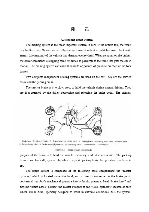
附录Automobile Brake SystemThe braking system is the most important system in cars. If the brakes fail, the result can be disastrous. Brakes are actually energy conversion devices, which convert the kinetic energy (momentum) of the vehicle into thermal energy (heat).When stepping on the brakes, the driver commands a stopping force ten times as powerful as the force that puts the car in motion. The braking system can exert thousands of pounds of pressure on each of the four brakes.Two complete independent braking systems are used on the car. They are the service brake and the parking brake.The service brake acts to slow, stop, or hold the vehicle during normal driving. They are foot-operated by the driver depressing and releasing the brake pedal. The primarypurpose of the brake is to hold the vehicle stationary while it is unattended. The parking brake is mechanically operated by when a separate parking brake foot pedal or hand lever is set.The brake system is composed of the following basic component s: the “master cylinder” which is located under the hood, and is directly connected to the brake pedal, converts driver foot’s mechanical pressure into hydraulic pressure. Steel “brake lines” and flexible “brake hoses” connect the master cylinder to the “slave cylinders” located at each wheel. Brake fluid, specially designed to work in extreme conditions, fills the system.“Shoes” and “pads” are pushed by the slave cylinders to contact the “drums” and “rotors” thus causing drag, which (hopefully) slows the car.The typical brake system consists of disk brakes in front and either disk or drum brakes in the rear connected by a system of tubes and hoses that link the brake at each wheel to the master cylinder (Figure).Basically, all car brakes are friction brakes. When the driver applies the brake, the control device forces brake shoes, or pads, against the rotating brake drum or disks at wheel. Friction between the shoes or pads and the drums or disks then slows or stops the wheel so that the car is braked.In most modern brake systems (see Figure 15.1), there is a fluid-filled cylinder, called master cylinder, which contains two separate sections, there is a piston in each section and both pistons are connected to a brake pedal in the driver’s compartment. Wh en the brake is pushed down, brake fluid is sent from the master cylinder to the wheels. At the wheels, the fluid pushes shoes, or pads, against revolving drums or disks. The friction between the stationary shoes, or pads, and the revolving drums or disks slows and stops them. This slows or stops the revolving wheels, which, in turn, slow or stop the car.The brake fluid reservoir is on top of the master cylinder. Most cars today have a transparent r reservoir so that you can see the level without opening the cover. The brake fluid level will drop slightly as the brake pads wear. This is a normal condition and no cause for concern. If the level drops noticeably over a short period of time or goes down to about two thirds full, have your brakes checked as soon as possible. Keep the reservoir covered except for the amount of time you need to fill it and never leave a cam of brake fluid uncovered. Brake fluid must maintain a very high boiling point. Exposure to air will cause the fluid to absorb moisture which will lower that boiling point.The brake fluid travels from the master cylinder to the wheels through a series of steel tubes and reinforced rubber hoses. Rubber hoses are only used in places that require flexibility, such as at the front wheels, which move up and down as well as steer. The rest of the system uses non-corrosive seamless steel tubing with special fittings at all attachment points. If a steel line requires a repair, the best procedure is to replace the compete line. If this is not practical, a line can be repaired using special splice fittings that are made for brake system repair. You must never use copper tubing to repair a brake system. They are dangerous and illegal.Drum brakes, it consists of the brake drum, an expander, pull back springs, a stationary back plate, two shoes with friction linings, and anchor pins. The stationary back plate is secured to the flange of the axle housing or to the steering knuckle. The brake drum is mounted on the wheel hub. There is a clearance between the inner surface of the drum and the shoe lining. To apply brakes, the driver pushes pedal, the expander expands the shoes and presses them to the drum. Friction between the brake drum and the friction linings brakes the wheels and the vehicle stops. To release brakes, the driver release the pedal, the pull back spring retracts the shoes thus permitting free rotation of the wheels.Disk brakes, it has a metal disk instead of a drum. A flat shoe, or disk-brake pad, is located on each side of the disk. The shoes squeeze the rotating disk to stop the car. Fluid from the master cylinder forces the pistons to move in, toward the disk. This action pushes the friction pads tightly against the disk. The friction between the shoes and disk slows and stops it. This provides the braking action. Pistons are made of either plastic or metal. There are three general types of disk brakes. They are the floating-caliper type, the fixed-caliper type, and the sliding-caliper type. Floating-caliper and sliding-caliper disk brakes use a single piston. Fixed-caliper disk brakes have either two or four pistons.The brake system assemblies are actuated by mechanical, hydraulic or pneumatic devices. The mechanical leverage is used in the parking brakes fitted in all automobile. When the brake pedal is depressed, the rod pushes the piston of brake master cylinder which presses the fluid. The fluid flows through the pipelines to the power brake unit and then to the wheel cylinder. The fluid pressure expands the cylinder pistons thus pressing the shoes to the drum or disk. If the pedal is released, the piston returns to the initial position, the pull back springs retract the shoes, the fluid is forced back to the master cylinder and braking ceases.The primary purpose of the parking brake is to hold the vehicle stationary while it is unattended. The parking brake is mechanically operated by the driver when a separate parking braking hand lever is set. The hand brake is normally used when the car has already stopped. A lever is pulled and the rear brakes are approached and locked in the “on” position. The car may now be left without fear of its rolling away. When the driver wants to move the car again, he must press a button before the lever can be released. The hand brake must also be able to stop the car in the event of the foot brake failing. For this reason, it is separate from the foot brake uses cable or rods instead of the hydraulic system.Anti-lock Brake SystemAnti-lock brake systems make braking safer and more convenient, Anti-lock brake systems modulate brake system hydraulic pressure to prevent the brakes from locking and the tires from skidding on slippery pavement or during a panic stop.Anti-lock brake systems have been used on aircraft for years, and some domestic car were offered with an early form of anti-lock braking in late 1990’s. Recently, several automakers have introduced more sophisticated anti-lock system. Investigations in Europe, where anti-lock braking systems have been available for a decade, have led one manufacture to state that the number of traffic accidents could be reduced by seven and a half percent if all cars had anti-lock brakes. So some sources predict that all cars will offer anti-lock brakes to improve the safety of the car.Anti-lock systems modulate brake application force several times per second to hold the tires at a controlled amount of slip; all systems accomplish this in basically the same way. One or more speed sensors generate alternating current signal whose frequency increases with the wheel rotational speed. An electronic control unit continuously monitors these signals and if the frequency of a signal drops too rapidly indicating that a wheel is about to lock, the control unit instructs a modulating device to reduce hydraulic pressure to the brake at the affected wheel. When sensor signals indicate the wheel is again rotating normally, the control unit allows increased hydraulic pressure to the brake. This release-apply cycle occurs several time per second to “pump” the brakes like a driver might but at a much faster rate.In addition to their basic operation, anti-lock systems have two other things in common. First, they do not operate until the brakes are applied with enough force to lock or nearly lock a wheel. At all other times, the system stands ready to function but does not interfere with normal braking. Second, if the anti-lock system fail in any way, the brakes continue to operate without anti-lock capability. A warning light on the instrument panel alerts the driver when a problem exists in the anti-lock system.The current Bosch component Anti-lock Braking System (ABSⅡ), is a second generation design wildly used by European automakers such as BWM, Mercedes-Benz and Porsche. ABSⅡsystem consists of : four wheel speed sensor, electronic control unit and modulator assembly.A speed sensor is fitted at each wheel sends signals about wheel rotation to control unit.Each speed sensor consists of a sensor unit and a gear wheel. The front sensor mounts to the steering knuckle and its gear wheel is pressed onto the stub axle that rotates with the wheel. The rear sensor mounts the rear suspension member and its gear wheel is pressed onto the axle. The sensor itself is a winding with a magnetic core. The core creates a magnetic field around the winding, and as the teeth of the gear wheel move through this field, an alternating current is induced in the winding. The control unit monitors the rate o change in this frequency to determine impending brake lockup.The control unit’s function can be divided into three parts: signal processing, logic and safety circuitry. The signal processing section is the converter that receives the alternating current signals form the speed sensors and converts them into digital form for the logic section. The logic section then analyzes the digitized signals to calculate any brake pressure changes needed. If impending lockup is sensed, the logic section sends commands to the modulator assembly.Modulator assemblyThe hydraulic modulator assembly regulates pressure to the wheel brakes when it receives commands from the control utuit. The modulator assembly can maintain or reduce pressure over the level it receives from the master cylinder, it also can never apply the brakes by itself. The modulator assembly consists of three high-speed electric solenoid valves, two fluid reservoirs and a turn delivery pump equipped with inlet and outlet check valves. The modulator electrical connector and controlling relays are concealed under a plastic cover of the assembly.Each front wheel is served by electric solenoid valve modulated independently by the control unit. The rear brakes are served by a single solenoid valve and modulated together using the select-low principle. During anti-braking system operation, the control unit cycles the solenoid valves to either hold or release pressure the brake lines. When pressure is released from the brake lines during anti-braking operation, it is routed to a fluid reservoir. There is one reservoir for the front brake circuit. The reservoirs are low-pressure accumulators that store fluid under slight spring pressure until the return delivery pump can return the fluid through the brake lines to the master cylinder.汽车制动系统制动系统是汽车中最重要的系统。
关于汽车制动系统英文作文英文:When it comes to the safety of a vehicle, the braking system is one of the most crucial components. The braking system is responsible for slowing down or stopping a vehicle when necessary. There are several types of braking systems, including disc brakes, drum brakes, and anti-lock braking systems (ABS).Disc brakes are the most common type of braking system used in modern vehicles. They consist of a rotor, caliper, and brake pads. When the brake pedal is pressed, thecaliper squeezes the brake pads against the rotor, creating friction and slowing down the vehicle. Disc brakes are known for their reliability and durability.Drum brakes, on the other hand, are becoming less common in modern vehicles. They consist of a brake drum, brake shoes, and a wheel cylinder. When the brake pedal ispressed, the brake shoes are pushed against the brake drum, creating friction and slowing down the vehicle. Drum brakes are known for their simplicity and low cost.ABS is a more advanced type of braking system that prevents the wheels from locking up during braking. This helps the driver maintain control of the vehicle and reduces the risk of skidding. ABS works by monitoring the speed of each wheel and adjusting the braking force accordingly.In addition to the types of braking systems, it's also important to regularly maintain and inspect the braking system. This includes checking the brake pads and rotorsfor wear, ensuring proper brake fluid levels, and checking for any leaks or damage.Overall, the braking system is a vital component of a vehicle's safety. It's important to understand thedifferent types of braking systems and how to properly maintain them to ensure a safe driving experience.中文:谈到车辆安全,制动系统是其中最关键的组成部分之一。

汽车制动系统-英文文献及翻译————————————————————————————————作者:————————————————————————————————日期:Brake systemsWe all know that pushing down on the brake pedal slows a car to a stop. But how does this happen? How does your car transmit the force from your leg to its wheels? How does it multiply the force so that it is enough to stop something as big as a car?Brake Image GalleryLayout of typical brake system. See more brake images.When you depress your brake pedal, your car transmits the force from your foot to its brakes through a fluid. Since the actual brakes require a much greater force than you could apply with your leg, your car must also multiply the force of your foot. It does this in two ways:•Mechanical advantage (leverage)•Hydraulic force multiplicationThe brakes transmit the force to the tires using friction, and the tires transmit that force to the road using friction also. Before we begin our discussion on the components of the brake system, we'll cover these three principles:•Leverage•Hydraulics•FrictionLeverage and HydraulicsIn the figure below, a force F is being applied to the left end of the lever. The left end of the lever is twice as long (2X) as the right end (X). Therefore, on the right end of the lever a force of 2F is available, but it acts through half of the distance (Y) that the left end moves (2Y). Changing the relative lengths of the left and right ends of the lever changes the multipliers.The pedal is designed in such a way that it can multiply the force from yourleg several times before any force is even transmitted to the brake fluid.The basic idea behind any hydraulic system is very simple: Force applied at one point is transmitted to another point using an incompressible fluid, almost always an oil of some sort. Most brake systems also multiply the force in the process. Here you can see the simplest possible hydraulic system:Your browser does not support JavaScript or it is disabled.Simple hydraulic systemIn the figure above, two pistons (shown in red) are fit into two glass cylinders filled with oil (shown in light blue) and connected to one another with an oil-filled pipe. If youapply a downward force to one piston (the left one, in this drawing), then the force is transmitted to the second piston through the oil in the pipe. Since oil is incompressible, the efficiency is very good -- almost all of the applied force appears at the second piston. The great thing about hydraulic systems is that the pipe connecting the two cylinders can be any length and shape, allowing it to snake through all sorts of things separating the twopistons. The pipe can also fork, so that one master cylinder can drive more than one slave cylinder if desired, as shown in here:Your browser does not support JavaScript or it is disabled.Master cylinder with two slavesThe other neat thing about a hydraulic system is that it makes force multiplication (or division) fairly easy. If you have read How a Block and Tackle Works or How Gear Ratios Work, then you know that trading force for distance is very common in mechanical systems. In a hydraulic system, all you have to do is change the size of one piston and cylinder relative to the other, as shown here:Your browser does not support JavaScript or it is disabled.Hydraulic multiplicationTo determine the multiplication factor in the figure above, start by looking at the size of the pistons. Assume that the piston on the left is 2 inches (5.08 cm) in diameter (1-inch / 2.54 cm radius), while the piston on the right is 6 inches (15.24 cm) in diameter (3-inch / 7.62 cm radius). The area of the two pistons is Pi * r2. The area of the left piston is therefore 3.14, while the area of the piston on the right is 28.26. The piston on the right is nine times larger than the piston on the left. This means that any force applied to theleft-hand piston will come out nine times greater on the right-hand piston. So, if you apply a 100-pound downward force to the left piston, a 900-pound upward force will appear on the right. The only catch is that you will have to depress the left piston 9 inches (22.86 cm) to raise the right piston 1 inch (2.54 cm).A Simple Brake SystemBefore we get into all the parts of an actual car brake system, let's look at a simplified system:Your browser does not support JavaScript or it is disabled.A simple brake systemYou can see that the distance from the pedal to the pivot is four times the distance from the cylinder to the pivot, so the force at the pedal will be increased by a factor of four before it is transmitted to the cylinder.You can also see that the diameter of the brake cylinder is three times the diameter of the pedal cylinder. This further multiplies the force by nine. All together, this system increases the force of your foot by a factor of 36. If you put 10 pounds of force on the pedal, 360 pounds (162 kg) will be generated at the wheel squeezing the brake pads.There are a couple of problems with this simple system. What if we have a leak? If it is a slow leak, eventually there will not be enough fluid left to fill the brake cylinder, and the brakes will not function. If it is a major leak, then the first time you apply the brakes all of the fluid will squirt out the leak and you will have complete brake failure.Drum brakes work on the same principle as disc brakes: Shoes press against a spinning surface. In this system, that surface is called a drum.Figure 1. Location of drum brakes. See more drum brakepictures.Many cars have drum brakes on the rear wheels and disc brakes on the front. Drum brakes have more parts than disc brakes and are harder to service, but they are less expensive to manufacture, and they easily incorporate an emergency brake mechanism.In this edition of HowStuffWorks, we will learn exactly how a drum brake system works, examine the emergency brake setup and find out what kind of servicing drum brakes need.Figure 2. Drum brake with drum in placeFigure 3. Drum brake without drum in placeLet's start with the basics.The Drum BrakeThe drum brake may look complicated, and it can be pretty intimidating when you open one up. Let's break it down and explain what each piece does.Figure 4. Parts of a drum brakeLike the disc brake, the drum brake has two brake shoes and a piston. But the drum brake also has an adjuster mechanism, an emergency brake mechanism and lots of springs.First, the basics: Figure 5 shows only the parts that provide stopping power.Your browser does not support JavaScript or it isdisabled.Figure 5. Drum brake in operationWhen you hit the brake pedal, the piston pushes the brake shoes against the drum. That's pretty straightforward, but why do we need all of those springs?This is where it gets a little more complicated. Many drum brakes are self-actuating. Figure 5 shows that as the brake shoes contact the drum, there is a kind of wedging action, which has the effect of pressing the shoes into the drum with more force.The extra braking force provided by the wedging action allows drum brakes to use a smaller piston than disc brakes. But, because of the wedging action, the shoes must be pulled away from the drum when the brakes are released. This is the reason for some of the springs. Other springs help hold the brake shoes in place and return the adjuster arm after it actuates.Brake AdjusterFor the drum brakes to function correctly, the brake shoes must remain close to the drum without touching it. If they get too far away from the drum (as the shoes wear down, for instance), the piston will require more fluid to travel that distance, and your brake pedal will sink closer to the floor when you apply the brakes. This is why most drum brakes have an automatic adjuster.Figure 6. Adjuster mechanismNow let's add in the parts of the adjuster mechanism. The adjuster uses theself-actuation principle we discussed above.Your browser does not support JavaScript or it is disabled.Figure 7. Drum brake adjuster in operationIn Figure 7, you can see that as the pad wears down, more space will form between the shoe and the drum. Each time the car stops while in reverse, the shoe is pulled tight against the drum. When the gap gets big enough, the adjusting lever rocks enough to advance the adjuster gear by one tooth. The adjuster has threads on it, like a bolt, so that it unscrews a little bit when it turns, lengthening to fill in the gap. When the brake shoes wear a little more, the adjuster can advance again, so it always keeps the shoes close to the drum.Some cars have an adjuster that is actuated when the emergency brake is applied. This type of adjuster can come out of adjustment if the emergency brake is not used forlong periods of time. So if you have this type of adjuster, you should apply your emergency brake at least once a week.ServicingThe most common service required for drum brakes is changing the brake shoes. Some drum brakes provide an inspection hole on the back side, where you can see how much material is left on the shoe. Brake shoes should be replaced when the friction material has worn down to within 1/32 inch (0.8 mm) of the rivets. If the friction material is bonded to the backing plate (no rivets), then the shoes should be replaced when they have only 1/16 inch (1.6 mm) of material left.Photo courtesy of a local AutoZone storeFigure 9. Brake shoeJust as in disc brakes, deep scores sometimes get worn into brake drums. If aworn-out brake shoe is used for too long, the rivets that hold the friction material to the backing can wear grooves into the drum. A badly scored drum can sometimes be repaired by refinishing. Where disc brakes have a minimum allowable thickness, drum brakes have a maximum allowable diameter. Since the contact surface is the inside of the drum, as you remove material from the drum brake the diameter gets bigger.Figure 10. Brake drum制动系统众所周知,踩下制动踏板可以使汽车减速至停止。
外文原文:ClutchThe clutch is located in the power train between the engine and the transmission. Its purpose is to permit the driver to couple or uncouple the engine and transmission.The clutch is a friction-type uncoupling device. It is linked to a clutch pedal in the river’s compartment. When the driver pushes down the clutch pedal, the linkage forces a flat disk, or plate, to move. The movement releases the pressure from a friction disk. With the pressure released. There is no friction at work in the clutch. And the power flow is therefore interrupted. Then, the engine runs without transmitting power to the power train.When the clutch is in the coupling(or normal running) position, power flows through it from the engine to the transmission. If the transmission is in gear, then power flows on through to the car wheels so that the car moves.Essentially , then, the clutch ha the job of permitting the driver to uncouple the engine temporarily so that the gears can be shifted from one to another forward gear position (or into reverse or neutral).It is necessary to interrupt the flow of power( by uncoupling) before gears are shifted. Otherwise, gear shifting would be extremely difficult if not impossible.The clutch contains friction disk(or driven plate)about 300millimetrein diameter. It also contains a spring arrangement and a pressure plate for pressing this disk tightly against the smooth rear face of the flywheel. The friction disk is splined to the clutch shaft. The splines consist of two sets of teeth, an internal set on the hub of the friction disk and a matching external set on the clutch shaft. They permit the friction disk to slide back and forth along the shaft but force the disk and the shaft to rotate together. All automotive clutches used with standard transmissions are very similar in construction and operation. There are some differences in the details of the linkages as well as in the pressure-plate assemblies. In addition , some clutches for heavy-duty applications have two friction disks and an intermediate pressure plate. Also, some clutches are operated by hydraulic means. Three types of clutch are the coil-pressure-spring type, diaphragm-spring type, and semicentrefugal type. Cars equipped with automatic transmission operateds automatically so that the driver is not required to use a clutch to shift gears.离合器在传动系统中,离合器位于发动机与变速器之间,其作用是使驾驶员可以把发动机与变速器结合或脱离.离合器是一种摩擦式分离装置,与驾驶室中离合踏板相连接. 当驾驶员踩下离合器踏板时, 联动装置使离合器的压盘移动. 这一运动减少了作用在摩擦盘上的压力. 随着压力的减小, 离合器工作状态下的摩擦力消失,动力被切断. 这样, 虽然发动机仍在转动, 而动力却不在传递到传动系统.当离合器处于结合状态时(或者说处于正常运行状态时),动力从发动机传递到变速器. 如果变速器已挂上适当的档位,那么动力就会传动到车轮上, 汽车即开动起来.从本质上说, 离合器的作用是使驾驶员可以暂时地切断发动机的动力. 这样一来,传动装置就可以从某一档换到另一档(或者换到倒档或空档).在变速之前,一定要切断动力传递.不然,换档即使不是完全不可能, 也会是十分困难的.离合器有一直径大约300毫米, 并带有摩擦衬片的圆盘, 还有一弹簧装置和一压力盘, 用来把摩擦盘紧紧地压在飞轮光滑地壁面上. 带有摩擦衬片的圆盘, 通过花键与离合器轴相连. 花键包括二套花键齿. 可以使摩擦盘沿着主轴向后或向前滑动, 又可以使圆盘和主轴同时移动.所有使用标准传动系统的汽车离合器在构造和操作上都很相似. 只是在压紧机构和连动装置的细节上稍有不同. 此外, 一些在重载荷情况下工作的离合器,有两个带摩擦衬片的圆盘和一个中间压力盘. 还有一些离合器是液压式的. 离合器的三种类型为:螺旋弹簧式, 嗼片弹簧式和半离心式.装有自动变速装置的汽车一般不需要离合器. 在这些汽车上, 变速器自动操作, 因此驾驶员不必使用离合器来换档.Brake SystemBrakes are necessary to slow or stop the car. Modern cars can travel very fast, so good brakes are essential for safety. Practically all cars use hydraulics brakes (which operate by applying pressure to a fluid). The brakes system can be divided into two principal parts, hydraulic system and wheel brake assemblies.In most modern brake systems, there is a fluid-filled cylinder, called the master cylinder, which contains two separate sections, there is a piston in each section and both pistons are connected to a brake pedal in the driver’s compartment. When the brake pedal is pushed by the driver the two pistons move in the two sections of the master cylinder. This forces brake fluid out and through the brake lines, or tubes , to the brake mechanisms at the wheels. In a typical system, the brake fluid from one section of the master cylinder goes to the two front-wheel brakes. The brake fluid from the other section goes to the two rear-wheel brakes. The purpose of this is that, if one section fails, the other section will still provide braking.There are two different types of brake mechanisms at the wheels, the drum-and-shoe type of brake , and the disk type. In the drum-and-shoe type, there is a wheel brake cylinder with two pistons. When brake fluid is forced into the brake cylinder by the action at the master cylinder , the two pistons are forced outward. This causes the curved brake shoes tomove into contact with the brake drum. The brake shoes apply friction to the brake drum, forcing it and the wheel to slow or stop.In the disk type, a rotating disk, attached to the wheel , is positioned between flat brake shoes. One or more pistons, actuated by the brake fluid from the master cylinder , force the shoes into contact with the rotating disk and this slows or stops the car.中文译文:制动系统制动系统必须能够强制汽车减速或停车. 现代汽车速度很快, 良好的制动系统是安全的基本保证. 实际上所有的汽车都使用液压制动(通过向液体加压来完成的).制动系统可以分为两个基本部分: 液压系统和车轮制动总成.大多数现代制动系统中具有充满液体的油缸, 叫做主缸, 主缸有两套各自独立的管路,每套管路各有一活塞, 并且两个活塞都与驾驶室中的制动踏板相连接. 当驾驶员踩动踏板时, 主缸的这两套管路中的两个活塞移动. 制动液从主缸中压出, 经油管进入各个车轮的制动装置中. 其目的是,如果其中一条管路失灵, 那么另一条关路仍然能够提供制动.车轮上有两种不同的制动机构: 蹄-鼓式制动器和盘式制动器. 在蹄-鼓式制动器中,有一个带有两个活塞的制动轮缸. 当制动液由于主缸的作用强制进入轮缸时,推动两个活塞向外侧移动. 这使得圆弧状的制动蹄与制动鼓想接触. 制动蹄对制动鼓所产生的摩擦力迫使制动鼓和车轮减速或停车.在盘式制动器中, 制动盘位于制动蹄之间, 与车轮相连接, 随车轮一起转动. 主缸的制动液推动一个或多个活塞, 将制动蹄片压在转动的制动盘上, 使汽车减速或停下.。

外文翻译---制动系统附录1Hydraulic Brake SystemsThe braking system is the most important system in cars. If the brake system fail, the result can be disastrous.When you step on the brake pedal, you expect the vehicle to stop. The brake pedal operates a hydraulic system that is used for two reasons. First, fluid under pressure can be carried to all parts of the vehicle by small hoses or metal lines with out taking up a lot of room or causing routing problems. Second, the hydraulic fluid offers a great mechanical advantage-little foot pressure is required on the pedal, but a great deal of pressure is generated at the wheels. The brake pedal is linked to a piston in the brake master cylinder, which is filled with hydraulic brake fluid. The master cylinder consists of a cylinder containing a small piston and a fluid reservoir.Modern master cylinders are actually two separate cylinders. Such a system is called a dual circuit, because the front cylinder is connected to the front brakes and the rear cylinder to the rear brakes. (Some vehicles are connected diagonally.) The two cylinders are actually separated, allowing for emergency stopping power should one part of the system fail.The entire hydraulic system from the master cylinder to the wheels is full of hydraulic brake fluid. When the brake pedal is depressed, the pistons in the master cylinder are forced to move, exerting tremendous force on the fluid in the lines. The fluid has nowhere to go, and forces the wheel cylinder pistons (drum brakes) or caliper pistons (disc brakes) to exert pressure on the brake shoes or pads. The friction between the brake shoe and wheel drum or the brake pad and rotor (disc) slows the vehicle and eventually stops it.Also attached to the brake pedal is a switch that lights the brake lights as the pedal is depressed. The lights stay on until the brake pedal is released and returns to its normal position.Each wheel cylinder in a drum brake system contains two pistons, one at either end, which push outward in opposite directions. In disc brake systems, the wheel cylinders are part of the caliper (there can be as many as four or as few asone). Whether disc or drum type, all pistons use some type of rubber seal to prevent leakage around the piston, and a rubber dust boot seals the outer ends of the wheel cylinders against dirt and moisture.When the brake pedal is released, a spring pushes the master cylinder pistons back to their normal positions. Check valves in the master cylinder piston allow fluid to flow toward the wheel cylinders or calipers as the piston returns. Then as the brake shoe return springs pull the brake shoes back to the released position, excess fluid returns to the master cylinder through compensating ports, which have been uncovered as the pistons move back. Any fluid that has leaked from the system will also be replaced through the compensating ports.All dual circuit brake systems use a switch to activate a light, warning of brake failure. The switch is located in a valve mounted near the master cylinder.A piston in the valve receives pressure on each end from the front and rear brake circuits. When the pressures are balanced, the piston remains stationary, but when one circuit has a leak, greater pressure during the application of the brakes will force the piston to one side or the other, closing the switch and activating the warning light. The light can also be activated by the ignition switch during engine starting or by the parking brake.Front disc, rear drum brake systems also have a metering valve to prevent the front disc brakes from engaging before the rear brakes have contacted the drums. This ensures that the front brakes will not normally be used alone to stop the vehicle. A proportioning valve is also used to limit pressure to the rear brakes to prevent rear wheel lock-up during hard braking.1. Friction materialsBrake shoes and pads are constructed in a similar manner. The pad or shoe is composed of a metal backing plate and a friction lining. The lining is either bonded (glued) to the metal, or riveted. Generally, riveted linings provide superior performance, but good quality bonded linings are perfectly adequate.Friction materials will vary between manufacturers and type of pad and the material compound may be referred to as: asbestos, organic, semi-metallic, metallic. The difference between these compounds lies in the types and percentages of friction materials used, material binders and performance modifiers.Generally speaking, organic and non-metallic asbestos compound brakesare quiet, easy on rotors and provide good feel. But this comes at the expense of high temperature operation, so they may not be your best choice for heavy duty use or mountain driving. In most cases, these linings will wear somewhat faster than metallic compound pads, so you will usually replace them more often. But, when using these pads, rotors tend to last longer.Semi-metallic or metallic compound brake linings will vary in performance based on the metallic contents of the compound. Again, generally speaking, the higher the metallic content, the better the friction material will resist heat. This makes them more appropriate for heavy duty applications, but at the expense of braking performance before the pad reaches operating temperature. The first few applications on a cold morning may not give strong braking. Also, metallic and semi-metallic are more likely to squeal. In most cases, metallic compounds last longer than non-metallic pads, but they tend to cause more wear on the rotors. If you use metallic pads, expect to replace the rotors more often.When deciding what type of brake lining is right for you, keep in mind that today's modern cars have brake materials which are matched to the expected vehicle's performance capabilities. Changing the material from OEM specification could adversely affect brake feel or responsiveness. Before changing the brake materials, talk to your dealer or parts supplier to help decide what is most appropriate for your application. Remember that heavy use applications such as towing, stop and go driving, driving down mountain roads, and racing may require a change to a higher performance material.Some more exotic materials are also used in brake linings, among which are Kevlar and carbon compounds. These materials have the capability of extremely good performance for towing, mountain driving or racing. Wear characteristics can be similar to either the metallic or the non-metallic linings, depending on the product you buy. Most race applications tend to wear like metallic linings, while many of the street applications are more like the non-metallic.2. Brake fluidOn a disk brake, the fluid from the master cylinder is forced into a caliper where it presses against a piston. The piston, in-turn, squeezes two brake pads against the disk(rotor)which is attached to the wheel, forcing it to slow down or stop. This process is similar to a bicycle brake where two rubber pads rub against the wheel rim creating friction.With drum brakes, fluid is forced into the wheel cylinder which pushes the brake shoes out so that the friction linings are pressed against the drum which is attached to the wheel, causing the wheel to stop.In either case, the friction surfaces of the pads on a disk brake system, or the shoes on a drum brake convert the forward motion of the vehicle into heat. Heat is what causes the friction surfaces (linings) of the pads and shoes to eventually wear out and require replacement.Brake fluid is a special oil that has specific properties. It is designed to withstand cold temperatures without thickening as well as very high temperatures without boiling.(If the brake fluid should boil, it will cause you to have a spongy pedal and the car will be hard to stop). Figure shows a brake hydraulic system.The brake fluid reservoir is on top of the master cylinder. Most cars today have a transparent r reservoir so that you can see the level without opening the cover. The brake fluid level will drop slightly as the brake pads wear. This is a normal condition and no cause for concern. If the level drops noticeably over a short period of time or goes down to about two thirds full, have your brakes checked as soon as possible. Keep the reservoir covered except for the amount of time you need to fill it and never leave a cam of brake fluid uncovered. Brake fluid must maintain a very high boiling point. Exposure to air will cause the fluid to absorb moisture which will lower that boiling point.The brake fluid travels from the master cylinder to the wheels through a series of steel tubes and reinforced rubber hoses. Rubber hoses are only used in places that require flexibility, such as at the front wheels, which move up and down as well as steer. The rest of the system uses non-corrosive seamless steel tubing with special fittings at all attachment points. If a steel line requires a repair, the best procedure is to replace the compete line. If this is not practical, a line can be repaired using special splice fittings that are made for brake system repair. You must never use copper tubing to repair a brake system. They are dangerous and illegal.制动系统制动系统是汽车中最重要的系统。
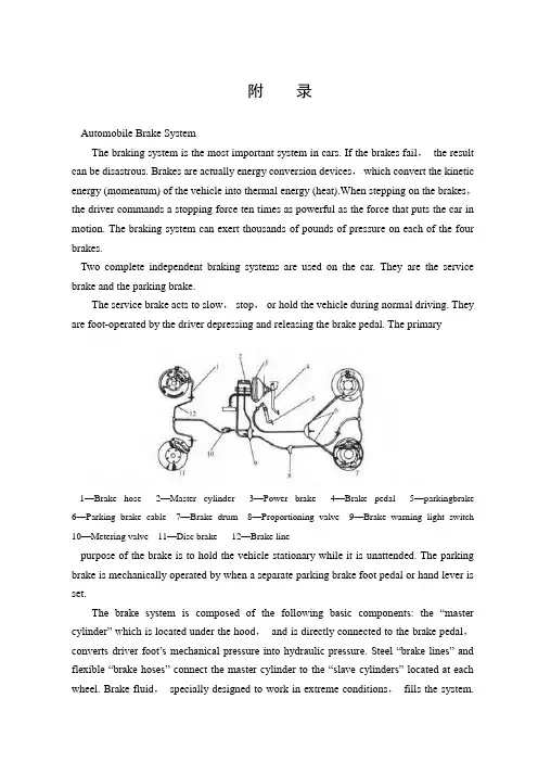
附录Automobile Brake SystemThe braking system is the most important system in cars. If the brakes fail,the result can be disastrous. Brakes are actually energy conversion devices,which convert the kinetic energy (momentum) of the vehicle into thermal energy (heat).When stepping on the brakes,the driver commands a stopping force ten times as powerful as the force that puts the car in motion. The braking system can exert thousands of pounds of pressure on each of the four brakes.Two complete independent braking systems are used on the car. They are the service brake and the parking brake.The service brake acts to slow,stop,or hold the vehicle during normal driving. They are foot-operated by the driver depressing and releasing the brake pedal. The primary1—Brake hose 2—Master cylinder 3—Power brake 4—Brake pedal 5—parkingbrake 6—Parking brake cable 7—Brake drum 8—Proportioning valve 9—Brake warning light switch 10—Metering valve 11—Disc brake 12—Brake linepurpose of the brake is to hold the vehicle stationary while it is unattended. The parking brake is mechanically operated by when a separate parking brake foot pedal or hand lever is set.The brake system is composed of the following basic components: the “master cylinder” which is located under the hood,and is directly connected to the brake pedal,converts driver foot’s mechanical pressure into hydraulic pressure. Steel “brake lines” and flexible “brake hoses” connect the master cylinder to the “slave cylinders” located at each wheel. Brake fluid,specially designed to work in extreme conditions,fills the system.“Shoes” and “pads” are pushed by the slave cylinders to contact the “drums” and “rotors” thus causing drag,which (hopefully) slows the car.The typical brake system consists of disk brakes in front and either disk or drum brakes in the rear connected by a system of tubes and hoses that link the brake at each wheel to the master cylinder (Figure).Basically,all car brakes are friction brakes. When the driver applies the brake,the control device forces brake shoes,or pads,against the rotating brake drum or disks at wheel. Friction between the shoes or pads and the drums or disks then slows or stops the wheel so that the car is braked.In most modern brake systems (see Figure 15.1),there is a fluid-filled cylinder,called master cylinder,which contains two separate sections,there is a piston in each section and both pistons are connected to a brake pedal in the driver’s compartment. When the brake is pushed down,brake fluid is sent from the master cylinder to the wheels. At the wheels,the fluid pushes shoes,or pads,against revolving drums or disks. The friction between the stationary shoes,or pads,and the revolving drums or disks slows and stops them. This slows or stops the revolving wheels,which,in turn,slow or stop the car. The brake fluid reservoir is on top of the master cylinder. Most cars today have a transparent r reservoir so that you can see the level without opening the cover. The brake fluid level will drop slightly as the brake pads wear. This is a normal condition and no cause for concern. If the level drops noticeably over a short period of time or goes down to about two thirds full,have your brakes checked as soon as possible. Keep the reservoir covered except for the amount of time you need to fill it and never leave a cam of brake fluid uncovered. Brake fluid must maintain a very high boiling point. Exposure to air will cause the fluid to absorb moisture which will lower that boiling point.The brake fluid travels from the master cylinder to the wheels through a series of steel tubes and reinforced rubber hoses. Rubber hoses are only used in places that require flexibility,such as at the front wheels,which move up and down as well as steer. The rest of the system uses non-corrosive seamless steel tubing with special fittings at all attachment points. If a steel line requires a repair,the best procedure is to replace the compete line. If this is not practical,a line can be repaired using special splice fittings that are made for brake system repair. You must never use copper tubing to repair a brake system. They are dangerous and illegal.Drum brakes,it consists of the brake drum,an expander,pull back springs,a stationary back plate,two shoes with friction linings,and anchor pins. The stationary back plate is secured to the flange of the axle housing or to the steering knuckle. The brake drum is mounted on the wheel hub. There is a clearance between the inner surface of the drum and the shoe lining. To apply brakes,the driver pushes pedal,the expander expands the shoes and presses them to the drum. Friction between the brake drum and the friction linings brakes the wheels and the vehicle stops. To release brakes,the driver release the pedal,the pull back spring retracts the shoes thus permitting free rotation of the wheels.Disk brakes,it has a metal disk instead of a drum. A flat shoe,or disk-brake pad,is located on each side of the disk. The shoes squeeze the rotating disk to stop the car. Fluid from the master cylinder forces the pistons to move in,toward the disk. This action pushes the friction pads tightly against the disk. The friction between the shoes and disk slows and stops it. This provides the braking action. Pistons are made of either plastic or metal. There are three general types of disk brakes. They are the floating-caliper type,the fixed-caliper type,and the sliding-caliper type. Floating-caliper and sliding-caliper disk brakes use a single piston. Fixed-caliper disk brakes have either two or four pistons.The brake system assemblies are actuated by mechanical,hydraulic or pneumatic devices. The mechanical leverage is used in the parking brakes fitted in all automobile. When the brake pedal is depressed,the rod pushes the piston of brake master cylinder which presses the fluid. The fluid flows through the pipelines to the power brake unit and then to the wheel cylinder. The fluid pressure expands the cylinder pistons thus pressing the shoes to the drum or disk. If the pedal is released,the piston returns to the initial position,the pull back springs retract the shoes,the fluid is forced back to the master cylinder and braking ceases.The primary purpose of the parking brake is to hold the vehicle stationary while it is unattended. The parking brake is mechanically operated by the driver when a separate parking braking hand lever is set. The hand brake is normally used when the car has already stopped. A lever is pulled and the rear brakes are approached and locked in the “on” position. The car may now be left without fear of its rolling away. When the driver wants to move the car again,he must press a button before the lever can be released. The hand brake must also be able to stop the car in the event of the foot brake failing. For this reason,it is separate from the foot brake uses cable or rods instead of the hydraulic system.Anti-lock Brake SystemAnti-lock brake systems make braking safer and more convenient,Anti-lock brake systems modulate brake system hydraulic pressure to prevent the brakes from locking and the tires from skidding on slippery pavement or during a panic stop.Anti-lock brake systems have been used on aircraft for years,and some domestic car were offered with an early form of anti-lock braking in late 1990’s. Recently,several automakers have introduced more sophisticated anti-lock system. Investigations in Europe,where anti-lock braking systems have been available for a decade,have led one manufacture to state that the number of traffic accidents could be reduced by seven and a half percent if all cars had anti-lock brakes. So some sources predict that all cars will offer anti-lock brakes to improve the safety of the car.Anti-lock systems modulate brake application force several times per second to hold the tires at a controlled amount of slip; all systems accomplish this in basically the same way. One or more speed sensors generate alternating current signal whose frequency increases with the wheel rotational speed. An electronic control unit continuously monitors these signals and if the frequency of a signal drops too rapidly indicating that a wheel is about to lock,the control unit instructs a modulating device to reduce hydraulic pressure to the brake at the affected wheel. When sensor signals indicate the wheel is again rotating normally,the control unit allows increased hydraulic pressure to the brake. This release-apply cycle occurs several time per second to “pump” the brakes like a driver might but at a much faster rate.In addition to their basic operation,anti-lock systems have two other things in common. First,they do not operate until the brakes are applied with enough force to lock or nearly lock a wheel. At all other times,the system stands ready to function but does not interfere with normal braking. Second,if the anti-lock system fail in any way,the brakes continue to operate without anti-lock capability. A warning light on the instrument panel alerts the driver when a problem exists in the anti-lock system.The current Bosch component Anti-lock Braking System (ABSⅡ),is a second generation design wildly used by European automakers such as BWM,Mercedes-Benz and Porsche. ABSⅡsystem consists of : four wheel speed sensor,electronic control unit and modulator assembly.A speed sensor is fitted at each wheel sends signals about wheel rotation to control unit.Each speed sensor consists of a sensor unit and a gear wheel. The front sensor mounts to the steering knuckle and its gear wheel is pressed onto the stub axle that rotates with the wheel. The rear sensor mounts the rear suspension member and its gear wheel is pressed onto the axle. The sensor itself is a winding with a magnetic core. The core creates a magnetic field around the winding,and as the teeth of the gear wheel move through this field,an alternating current is induced in the winding. The control unit monitors the rate o change in this frequency to determine impending brake lockup.The control unit’s function can be divided into three parts: signal processing,logic and safety circuitry. The signal processing section is the converter that receives the alternating current signals form the speed sensors and converts them into digital form for the logic section. The logic section then analyzes the digitized signals to calculate any brake pressure changes needed. If impending lockup is sensed,the logic section sends commands to the modulator assembly.Modulator assemblyThe hydraulic modulator assembly regulates pressure to the wheel brakes when it receives commands from the control utuit. The modulator assembly can maintain or reduce pressure over the level it receives from the master cylinder,it also can never apply the brakes by itself. The modulator assembly consists of three high-speed electric solenoid valves,two fluid reservoirs and a turn delivery pump equipped with inlet and outlet check valves. The modulator electrical connector and controlling relays are concealed under a plastic cover of the assembly.Each front wheel is served by electric solenoid valve modulated independently by the control unit. The rear brakes are served by a single solenoid valve and modulated together using the select-low principle. During anti-braking system operation,the control unit cycles the solenoid valves to either hold or release pressure the brake lines. When pressure is released from the brake lines during anti-braking operation,it is routed to a fluid reservoir. There is one reservoir for the front brake circuit. The reservoirs are low-pressure accumulators that store fluid under slight spring pressure until the return delivery pump can return the fluid through the brake lines to the master cylinder.汽车制动系统制动系统是汽车中最重要的系统。
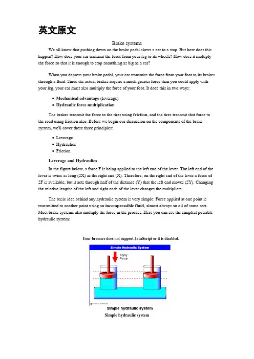
英文原文Brake systemsWe all know that pushing down on the brake pedal slows a car to a stop. But how does this happen? How does your car transmit the force from your leg to its wheels? How does it multiply the force so that it is enough to stop something as big as a car?When you depress your brake pedal, your car transmits the force from your foot to its brakes through a fluid. Since the actual brakes require a much greater force than you could apply with your leg, your car must also multiply the force of your foot. It does this in two ways:∙Mechanical advantage (leverage)∙Hydraulic force multiplicationThe brakes transmit the force to the tires using friction, and the tires transmit that force to the road using friction also. Before we begin our discussion on the components of the brake system, we'll cover these three principles:∙Leverage∙Hydraulics∙FrictionLeverage and HydraulicsIn the figure below, a force F is being applied to the left end of the lever. The left end of the lever is twice as long (2X) as the right end (X). Therefore, on the right end of the lever a force of 2F is available, but it acts through half of the distance (Y) that the left end moves (2Y). Changing the relative lengths of the left and right ends of the lever changes the multipliers.The basic idea behind any hydraulic system is very simple: Force applied at one point is transmitted to another point using an incompressible fluid, almost always an oil of some sort. Most brake systems also multiply the force in the process. Here you can see the simplest possible hydraulic system:Your browser does not support JavaScript or it is disabled.Simple hydraulic systemIn the figure above, two pistons (shown in red) are fit into two glass cylinders filled with oil (shown in light blue) and connected to one another with an oil-filled pipe. If you apply adownward force to one piston (the left one, in this drawing), then the force is transmitted to the second piston through the oil in the pipe. Since oil is incompressible, the efficiency is very good -- almost all of the applied force appears at the second piston. The great thing about hydraulic systems is that the pipe connecting the two cylinders can be any length and shape, allowing it to snake through all sorts of things separating the two pistons. The pipe can also fork, so that one master cylinder can drive more than one slave cylinder if desired, as shown in here:Your browser does not support JavaScript or it is disabled.Master cylinder with two slavesThe other neat thing about a hydraulic system is that it makes force multiplication (or division) fairly easy. If you have read How a Block and Tackle Works or How Gear Ratios Work, then you know that trading force for distance is very common in mechanical systems. In a hydraulic system, all you have to do is change the size of one piston and cylinder relative to the other, as shown here:Your browser does not support JavaScript or it is disabled.Hydraulic multiplicationTo determine the multiplication factor in the figure above, start by looking at the size of the pistons. Assume that the piston on the left is 2 inches (5.08 cm) in diameter (1-inch / 2.54 cm radius), while the piston on the right is 6 inches (15.24 cm) in diameter (3-inch / 7.62 cm radius).The area of the two pistons is Pi * r2. The area of the left piston is therefore 3.14, while the area of the piston on the right is 28.26. The piston on the right is nine times larger than the piston on the left. This means that any force applied to the left-hand piston will come out nine times greater on the right-hand piston. So, if you apply a 100-pound downward force to the left piston, a 900-pound upward force will appear on the right. The only catch is that you will have to depress the left piston 9 inches (22.86 cm) to raise the right piston 1 inch (2.54 cm).A Simple Brake SystemBefore we get into all the parts of an actual car brake system, let's look at a simplified system:Your browser does not support JavaScript or it is disabled.A simple brake systemYou can see that the distance from the pedal to the pivot is four times the distance from the cylinder to the pivot, so the force at the pedal will be increased by a factor of four before it is transmitted to the cylinder.You can also see that the diameter of the brake cylinder is three times the diameter of the pedal cylinder. This further multiplies the force by nine. All together, this system increases the force of your foot by a factor of 36. If you put 10 pounds of force on the pedal, 360 pounds (162 kg) will be generated at the wheel squeezing the brake pads.There are a couple of problems with this simple system. What if we have a leak? If it is a slow leak, eventually there will not be enough fluid left to fill the brake cylinder, and the brakes will not function. If it is a major leak, then the first time you apply the brakes all of the fluid will squirt out the leak and you will have complete brake failure.Drum brakes work on the same principle as disc brakes: Shoes press against a spinning surface. In this system, that surface is called a drum.Figure 1. Location of drum brakes. See more drum brake pictures.Many cars have drum brakes on the rear wheels and disc brakes on the front. Drum brakes have more parts than disc brakes and are harder to service, but they are less expensive to manufacture, and they easily incorporate an emergency brake mechanism.In this edition of HowStuffWorks, we will learn exactly how a drum brake system works, examine the emergency brake setup and find out what kind of servicing drum brakes need.Figure 2. Drum brake with drum in placeFigure 3. Drum brake without drum in placeLet's start with the basics.The Drum BrakeThe drum brake may look complicated, and it can be pretty intimidating when you open one up. Let's break it down and explain what each piece does.Figure 4. Parts of a drum brakeLike the disc brake, the drum brake has two brake shoes and a piston. But the drum brake also has an adjuster mechanism, an emergency brake mechanism and lots of springs.First, the basics: Figure 5 shows only the parts that provide stopping power.Your browser does not support JavaScript or it is disabled.Figure 5. Drum brake in operationWhen you hit the brake pedal, the piston pushes the brake shoes against the drum. That's pretty straightforward, but why do we need all of those springs?This is where it gets a little more complicated. Many drum brakes are self-actuating. Figure 5 shows that as the brake shoes contact the drum, there is a kind of wedging action, which has the effect of pressing the shoes into the drum with more force.The extra braking force provided by the wedging action allows drum brakes to use a smaller piston than disc brakes. But, because of the wedging action, the shoes must be pulled away from the drum when the brakes are released. This is the reason for some of the springs. Other springs help hold the brake shoes in place and return the adjuster arm after it actuates.Brake AdjusterFor the drum brakes to function correctly, the brake shoes must remain close to the drum without touching it. If they get too far away from the drum (as the shoes wear down, for instance), the piston will require more fluid to travel that distance, and your brake pedal will sink closer to the floor when you apply the brakes. This is why most drum brakes have an automatic adjuster.Figure 6. Adjuster mechanismNow let's add in the parts of the adjuster mechanism. The adjuster uses the self-actuation principle we discussed above.Your browser does not support JavaScript or it is disabled.Figure 7. Drum brake adjuster in operationIn Figure 7, you can see that as the pad wears down, more space will form between the shoe and the drum. Each time the car stops while in reverse, the shoe is pulled tight against the drum. When the gap gets big enough, the adjusting lever rocks enough to advance the adjuster gear by one tooth. The adjuster has threads on it, like a bolt, so that it unscrews a little bit when it turns, lengthening to fill in the gap. When the brake shoes wear a little more, the adjuster can advance again, so it always keeps the shoes close to the drum.Some cars have an adjuster that is actuated when the emergency brake is applied. This type of adjuster can come out of adjustment if the emergency brake is not used for long periods of time. So if you have this type of adjuster, you should apply your emergency brake at least once a week.ServicingThe most common service required for drum brakes is changing the brake shoes. Some drum brakes provide an inspection hole on the back side, where you can see how much material is left on the shoe. Brake shoes should be replaced when the friction material has worn down to within 1/32 inch (0.8 mm) of the rivets. If the friction material is bonded to the backing plate (no rivets), then the shoes should be replaced when they have only 1/16 inch (1.6 mm) of material left.Photo courtesy of a local AutoZone storeFigure 9. Brake shoeJust as in disc brakes, deep scores sometimes get worn into brake drums. If a worn-out brake shoe is used for too long, the rivets that hold the friction material to the backing can wear grooves into the drum. A badly scored drum can sometimes be repaired by refinishing. Where disc brakes have a minimum allowable thickness, drum brakes have a maximum allowable diameter. Since the contact surface is the inside of the drum, as you remove material from the drum brake the diameter gets bigger.The current Bosch component Anti-lock Braking System (ABSⅡ), is a second generation design wildly used by European automakers such as BWM, Mercedes-Benz and Porsche. ABSⅡsystem consists of : four wheel speed sensor, electronic control unit and modulator assembly.A speed sensor is fitted at each wheel sends signals about wheel rotation to control unit. Each speed sensor consists of a sensor unit and a gear wheel. The front sensor mounts to the steering knuckle and its gear wheel is pressed onto the stub axle that rotates with the wheel. The rear sensor mounts the rear suspension member and its gear wheel is pressed onto the axle. The sensor itself is a winding with a magnetic core. The core creates a magnetic field around the winding, and as the teeth of the gear wheel move through this field, an alternating current is induced in the winding. The control unit monitors the rate o change in this frequency to determine impending brake lockup.The control unit’s function can be divided into three parts: signal processing, logic and safety circuitry. The signal processing section is the converter that receives the alternating current signals form the speed sensors and converts them into digital form for the logic section. The logic section then analyzes the digitized signals to calculate any brake pressure changes needed. If impending lockup is sensed, the logic section sends commands to the modulator assembly.The hydraulic modulator assembly regulates pressure to the wheel brakes when it receives commands from the control utuit. The modulator assembly can maintain or reduce pressure over the level it receives from the master cylinder, it also can never apply the brakes by itself. The modulator assembly consists of three high-speed electric solenoid valves, two fluid reservoirs and a turn delivery pump equipped with inlet and outlet check valves. The modulator electrical connector and controlling relays are concealed under a plastic cover of the assembly.Each front wheel is served by electric solenoid valve modulated independently by the control unit. The rear brakes are served by a single solenoid valve and modulated together using the select-low principle. During anti-braking system operation, the control unit cycles the solenoidvalves to either hold or release pressure the brake lines. When pressure is released from the brake lines during anti-braking operation, it is routed to a fluid reservoir. There is one reservoir for the front brake circuit. The reservoirs are low-pressure accumulators that store fluid under slight spring pressure until the return delivery pump can return the fluid through the brake lines to the master cylinder.中文译文制动系统众所周知,踩下制动踏板可以使汽车减速至停止。
汽车检测与维修专业外文翻译汽车制动系统Automobile Brake SystemThe braking system is the most important system in cars. If the brakes fail, the result can be disastrous. Brakes are actually energy conversion devices, which convert the kinetic energy (momentum) of the vehicle into thermal energy (heat).When stepping on the brakes, the driver commands a stopping force ten times as powerful as the force that puts the car in motion. The braking system can exert thousands of pounds of pressure on each of the four brakes.Two complete independent braking systems are used on the car. They are the service brake and the parking brake.The service brake acts to slow, stop, or hold the vehicle during normal driving. They are foot-operated by the driver depressing and releasing the brake pedal. The primary purpose of the brake is to hold the vehicle stationary while it is unattended. The parking brake is mechanically operated by when a separate parking brake foot pedal or hand lever is set.The brake system is composed of the following basic components: the “master cylinder” which is located under the hood, and is directly connected to the brake pedal, converts driver foot’s mechanical pressure into hydraulic pressure. Steel “brake lines” and flexible “brake hoses” connect the master cylinder to the “slave cylinders” located at each wheel. Brake fluid, specially designed to work in extreme conditions, fills the system. “Shoes” and “pads” are pushed by the slave cylinders to contact the “drums” and “rotors” thus causing drag, which (hopefully) slows the car.The typical brake system consists of disk brakes in front andeither disk or drum brakes in the rear connected by a system of tubes and hoses that link the brake at each wheel to the master cylinder (Figure).Basically, all car brakes are friction brakes. When the driver applies the brake, the control device forces brake shoes, or pads, against the rotating brake drum or disks at wheel. Friction between the shoes or pads and the drums or disks then slows or stops the wheel so that the car is braked.In most modern brake systems (see Figure 15.1), there is a fluid-filled cylinder, called master cylinder, which contains two separate sections, there is a piston in each section and both pistons are connected to a brake pedal in the driver’s compartment. When the brake is pushed down, brake fluid is sent from the master cylinder to the wheels.At the wheels, the fluid pushes shoes, or pads, against revolving drums or disks. The friction between the stationary shoes, or pads, and the revolving drums or disks slows and stops them. This slows or stops the revolving wheels, which, in turn, slow or stop the car.The brake fluid reservoir is on top of the master cylinder. Most cars today have a transparent r reservoir so that you can see the level without opening the cover. The brake fluid level will drop slightly as the brake pads wear. This is a normal condition and no cause for concern. If the level drops noticeably over ashort period of time or goes down to about two thirds full, have your brakes checked as soon as possible. Keep the reservoir covered except for the amount of time you need to fill it and never leave a cam of brake fluid uncovered. Brake fluid must maintain a very high boiling point. Exposure to air will cause the fluid to absorb moisture which will lower that boiling point.The brake fluid travels from the master cylinder to the wheels through a series of steel tubes and reinforced rubber hoses. Rubberhoses are only used in places that require flexibility, such as at the front wheels, which move up and down as well as steer. The rest of the system uses non-corrosive seamless steel tubing with special fittings at all attachment points. If a steel line requires a repair, the best procedure is to replace the compete line. If this is not practical, a line can be repaired using special splice fittings that are made for brake system repair. You must never use copper tubing to repair a brake system. They are dangerous and illegal.Drum brakes, it consists of the brake drum, an expander, pull back springs, a stationary back plate, two shoes with friction linings, and anchor pins. The stationary back plate is secured to the flange of the axle housing or to the steering knuckle. The brake drum is mounted on the wheel hub. There is a clearance between the inner surface of the drum and the shoe lining. To apply brakes, the driver pushes pedal, the expander expands the shoes and presses them to the drum. Friction between the brake drum and the friction linings brakes the wheels and the vehicle stops. To release brakes, the driver release the pedal, the pull back spring retracts the shoes thus permitting free rotation of the wheels.Disk brakes, it has a metal disk instead of a drum. A flat shoe, or disk-brake pad, is located on each side of the disk. The shoes squeeze the rotatin g disk to stop the car. Fluid from the master cylinder forces the pistons to move in, toward the disk. This action pushes the friction pads tightly against the disk. The friction between the shoes and disk slows and stops it. This provides the braking action. Pistons are made of either plastic or metal. There are three general types of disk brakes. They are the floating-caliper type, the fixed-caliper type, and the sliding-caliper type. Floating-caliper and sliding-caliper disk brakes use a single piston. Fixed-caliper disk brakes have either two or four pistons.The brake system assemblies are actuated by mechanical,hydraulic or pneumatic devices. The mechanical leverage is used in the parking brakes fitted in all automobile. When the brake pedal is depressed, the rod pushes the piston of brake master cylinder which presses the fluid. The fluid flows through the pipelines to the power brake unit and then to the wheel cylinder. The fluid pressure expands the cylinder pistons thus pressing the shoes to the drum or disk. If the pedal is released, the piston returns to the initialposition, the pull back springs retract the shoes, the fluid is forced back to the master cylinder and braking ceases.The primary purpose of the parking brake is to hold the vehicle stationary while it is unattended. The parking brake is mechanically operated by the driver when a separate parking braking hand lever is set. The hand brake is normally used when the car has already stopped.A lever is pulled and the rear brakes are approached and locked in the “on” position. The car may now be left without fear of its rolling away. When the driver wants to move the car again, he must press a button before the lever can be released. The hand brake must also be able to stop the car in the event of the foot brake failing. For this reason, it is separate from the foot brake uses cable or rods instead of the hydraulic system.Anti-lock Brake SystemAnti-lock brake systems make braking safer and more convenient, Anti-lock brake systems modulate brake system hydraulic pressure to prevent the brakes from locking and the tires from skidding on slippery pavement or during a panic stop.Anti-lock brake systems have been used on aircraft for years, and some domestic car were offered with an early form of anti-lock braking in late 1990’s. Recently, several automakers have introduced more sophisticated anti-lock system. Investigations in Europe, where anti-lock brakin g systems have been available for a decade, have led one manufacture to state that the number of traffic accidents could bereduced by seven and a half percent if all cars had anti-lock brakes. So some sources predict that all cars will offer anti-lock brakes to improve the safety of the car.Anti-lock systems modulate brake application force several times per second to hold the tires at a controlled amount of slip; all systems accomplish this in basically the same way. One or more speed sensors generate alternating current signal whose frequency increases with the wheel rotational speed. An electronic control unit continuously monitors these signals and if the frequency of a signal drops too rapidly indicating that a wheel is about to lock, the control unit instructs a modulating device to reduce hydraulic pressure to the brake at the affected wheel. When sensor signals indicate the wheel is again rotating normally, the control unit allows increased hydraulic pressure to the brake. This release-apply cycle occurs several time per second to “pump” the brakes like a driver might but at a much faster rate.In addition to their basic operation, anti-lock systems have two other things in common. First, they do not operate until the brakes are applied with enough force to lock or nearly lock a wheel. At all other times, the system stands ready to function but does not interfere with normal braking. Second, if the anti-lock system fail in any way, the brakes continue to operate without anti-lock capability. A warning light on the instrument panel alerts the driver when a problem exists in the anti-lock system.The current Bosch component Anti-lock Braking System (ABSⅡ), is a second generation design wildly used by European automakers such as BWM, Mercedes-Benz and Porsche. ABSⅡ system consists of: four wheel speed sensor, electronic control unit and modulator assembly.A speed sensor is fitted at each wheel sends signals about wheel rotation to control unit. Each speed sensor consists of a sensor unit and a gear wheel. The front sensor mounts to the steering knuckle andits gear wheel is pressed onto the stub axle that rotates with the wheel. The rear sensor mounts the rear suspension member and its gear wheel is pressed onto the axle. The sensor itself is a winding with a magnetic core. The core creates a magnetic field around the winding, and as the teeth of the gear wheel move through this field, an alternating current is induced in the winding. The control unit monitors the rate o change in this frequency to determine impending brake lockup.The control unit’s function can be divided into three parts: signal processing, logic and safety circuitry. The signal processing section is the converter that receives the alternating current signals form the speed sensors and converts them into digital form for the logic section. The logic section then analyzes the digitized signals to calculate any brake pressure changes needed. If impending lockup is sensed, the logic section sends commands to the modulator assembly.Modulator assemblyThe hydraulic modulator assembly regulates pressure to the wheel brakes when it receives commands from the control utuit. The modulator assembly can maintain or reduce pressure over the level it receives from the master cylinder, it also can never apply the brakes by itself. The modulator assembly consists of three high-speed electric solenoid valves, two fluid reservoirs and a turn delivery pump equipped with inlet and outlet check valves. The modulator electrical connector and controlling relays are concealed under a plastic cover of the assembly.Each front wheel is served by electric solenoid valve modulated independently by the control unit. The rear brakes are served by a single solenoid valve and modulated together using the select-low principle. During anti-braking system operation, the control unit cycles the solenoid valves to either hold or release pressure the brake lines. When pressure is released from the brake lines during anti-braking operation, it is routed to a fluid reservoir. There is onereservoir for the front brake circuit. The reservoirs are low-pressure accumulators that store fluid under slight spring pressure until the return delivery pump can return the fluid through the brake lines to the master cylinder.汽车制动系统汽车制动系统系统是汽车中最重要的系统。
分类号编号毕业论文题目汽车防抱制动系统的建模与仿真——模糊控制在ABS中的应用学院机械学院专业机械设计制造及其自动化毕业设计任务书设计题目:汽车防抱制动系统的建模与仿真专业:机械设计制造及其自动化班级学号:姓名:院、系:机械学院2010年2 月26 日一、毕业设计的目的毕业设计是本科教育中培养学生的重要的实践性教学环节,也是最后一个教学环节。
其目的:1.培养学生综合运用基础理论知识、专业知识和技能,解决工程实际问题的能力;2.培养学生运用机械设计手册、图册、国家标准规范和规程的能力;3.培养学生学会机械设计的思想、方法和步骤,掌握计算方法、掌握计算机绘图及编写工程设计文件等基本技能;4.提高学生分析问题、解决问题和独立工作的能力。
二、主要设计内容1.专业外文资料翻译;2.毕业实习,实习报告;3.开题报告;4.汽车防抱制动系统的建模与仿真。
三、重点研究问题1.汽车防抱制动系统的车辆仿真模型的建立;2.采用的控制方法模型的建立;四、主要技术指标和主要设计参数1.收集资料确定一个自己的设计参数,在查阅资料后确定下来。
2.控制方法根据所查找文献自己确定。
五、设计成果要求1.开题报告1份(要求3 000字左右、查阅文献10篇以上、文献综述引用5篇以上,样表从教务处表格下载中下载);2.实习报告1份;3.专业外文资料翻译1篇(不少于2 000汉字);4.毕业设计(论文)1份(设计说明书应在10000字以上,论文应在6000字以上,包括封面、任务书、开题报告、中英文摘要、目录、正文、参考文献、附录);5.设计图纸一套(不少于A0图2张);6.所有内容电子文档一套;7.毕业论文成果材料清单一份。
本科生毕业设计开题报告2010 年 03 月 30日学生姓名学号专业机械设计制造及其自动化题目名称汽车防抱死制动系统的建模与仿真课题来源自选主要内容一.本课题设计的目的与意义本课题为《汽车防抱制动系统的建模与仿真》,要求我们收集资料自己确定一个设计参数,并查阅相关文献选择一种ABS的控制方法。
英文资料SuspensionSuspension is the term given to the system of springs, shock absorbers and linkages that connects a vehicle to its wheels. Suspension systems serve a dual purpose –contributing to the car's roadholding/handling and braking for good active safety and driving pleasure, and keeping vehicle occupants comfortable and reasonably well isolated from road noise, bumps, and vibrations,etc. These goals are generally at odds, so the tuning of suspensions involves finding the right compromise. It is important for the suspension to keep the road wheel in contact with the road surface as much as possible, because all the forces acting on the vehicle do so through the contact patches of the tires. The suspension also protects the vehicle itself and any cargo or luggage from damage and wear. The design of front and rear suspension of a car may be different.Leaf springs have been around since the early Egyptians.Ancient military engineers used leaf springs in the form of bows to power their siege engines, with little success at first. The use of leaf springs in catapults was later refined and made to work years later. Springs were not only made of metal, a sturdy tree branch could be used as a spring, such as with a bow.Horse drawn vehiclesBy the early 19th century most British horse carriages were equipped with springs; wooden springs in the case of light one-horse vehicles to avoid taxation, and steel springs in larger vehicles. These were made of low-carbon steel and usually took the form of multiple layer leaf springs.[1]The British steel springs were not well suited for use on America's rough roads of the time, and could even cause coaches to collapse if cornered too fast. In the 1820s, the Abbot Downing Company of Concord, New Hampshire developed a system whereby the bodies of stagecoaches were supported on leather straps called "thoroughbraces", which gave a swinging motion instead of the jolting up and down of a spring suspension (the stagecoach itself was sometimes called a "thoroughbrace")AutomobilesAutomobiles were initially developed as self-propelled versions of horse drawn vehicles. However, horse drawn vehicles had been designed for relatively slow speeds and their suspension was not well suited to the higher speeds permitted by the internal combustion engine.In 1903 Mors of Germany first fitted an automobile with shock absorbers. In 1920 Leyland used torsion bars in a suspension system. In 1922 independent front suspension was pioneered on the Lancia Lambda and became more common in mass market cars from 1932.[2]Important propertiesSpring rateThe spring rate (or suspension rate) is a component in setting the vehicle's ride height or its location in the suspension stroke. Vehicles which carry heavy loads will often have heavier springs to compensate for the additional weight that would otherwise collapse a vehicle to the bottom of its travel (stroke). Heavier springs are also used in performance applications where the loading conditions experienced are more extreme. Springs that are too hard or too soft cause the suspension to become ineffective because they fail to properly isolate the vehicle from the road. Vehicles that commonly experience suspension loads heavier than normal have heavy or hard springs with a spring rate close to the upper limit for that vehicle's weight. This allows the vehicle to perform properly under a heavy load when control is limited by the inertia of the load. Riding in an empty truck used for carrying loads can be uncomfortable for passengers because of its high spring rate relative to the weight of the vehicle. A race car would also be described as having heavy springs and would also be uncomfortably bumpy. However, even though we say they both have heavy springs, the actual spring rates for a 2000 lb race car and a 10,000 lb truck are very different. A luxury car, taxi, or passenger bus would be described as having soft springs. Vehicles with worn out or damaged springs ride lower to the ground which reduces the overall amount of compression available to the suspension and increases the amount of body lean. Performance vehicles can sometimes have spring rate requirements other than vehicle weight and load.Mathematics of the spring rateSpring rate is a ratio used to measure how resistant a spring is to being compressed or expanded during the spring's deflection. The magnitude of the spring force increases as deflection increases according to Hooke's Law. Briefly, this can be stated aswhereF is the force the spring exertsk is the spring rate of the spring.x is the displacement from equilibrium length i.e. the length at which the spring is neither compressed or stretched.Spring rate is confined to a narrow interval by the weight of the vehicle,load the vehicle will carry, and to a lesser extent by suspension geometry and performance desires.Spring rates typically have units of N/mm (or lbf/in). An example of a linear spring rate is 500 lbf/in. For every inch the spring is compressed, it exerts 500 lbf. Anon-linear spring rate is one for which the relation between the spring's compression and the force exerted cannot be fitted adequately to a linear model. For example, the first inch exerts 500 lbf force, the second inch exerts an additional 550 lbf (for a total of 1050 lbf), the third inch exerts another 600 lbf (for a total of 1650 lbf). In contrast a 500 lbf/in linear spring compressed to 3 inches will only exert 1500 lbf.The spring rate of a coil spring may be calculated by a simple algebraic equation or it may be measured in a spring testing machine. The spring constant k can be calculated as follows:where d is the wire diameter, G is the spring's shear modulus (e.g., about 12,000,000 lbf/in² or 80 GPa for steel), and N is the number of wraps and D is the diameter of the coil.Wheel rateWheel rate is the effective spring rate when measured at the wheel. This is as opposed to simply measuring the spring rate alone.Wheel rate is usually equal to or considerably less than the spring rate. Commonly, springs are mounted on control arms, swing arms or some other pivoting suspension member. Consider the example above where the spring rate was calculated to be500 lbs/inch, if you were to move the wheel 1 inch (without moving the car), the spring more than likely compresses a smaller amount. Lets assume the spring moved 0.75 inches, the lever arm ratio would be 0.75 to 1. The wheel rate is calculated by taking the square of the ratio (0.5625) times the spring rate. Squaring the ratio is because the ratio has two effects on the wheel rate. The ratio applies to both the force and distance traveled.Wheel rate on independent suspension is fairly straight-forward. However, special consideration must be taken with some non-independent suspension designs. Take the case of the straight axle. When viewed from the front or rear, the wheel rate can be measured by the means above. Yet because the wheels are not independent, when viewed from the side under acceleration or braking the pivot point is at infinity (because both wheels have moved) and the spring is directly inline with the wheel contact patch. The result is often that the effective wheel rate under cornering is different from what it is under acceleration and braking. This variation in wheel rate may be minimized by locating the spring as close to the wheel as possible.Roll couple percentageRoll couple percentage is the effective wheel rates, in roll, of each axle of the vehicle just as a ratio of the vehicle's total roll rate. Roll Couple Percentage is critical in accurately balancing the handling of a vehicle. It is commonly adjusted through the use of anti-roll bars, but can also be changed through the use of different springs.A vehicle with a roll couple percentage of 70% will transfer 70% of its sprung weight transfer at the front of the vehicle during cornering. This is also commonly known as "Total Lateral Load Transfer Distribution" or "TLLTD".Weight transferWeight transfer during cornering, acceleration or braking is usually calculated per individual wheel and compared with the static weights for the same wheels.The total amount of weight transfer is only affected by 4 factors: the distance between wheel centers (wheelbase in the case of braking, or track width in the case of cornering) the height of the center of gravity, the mass of the vehicle, and the amount of acceleration experienced.The speed at which weight transfer occurs as well as through which components it transfers is complex and is determined by many factors including but not limited to roll center height, spring and damper rates, anti-roll bar stiffness and the kinematic design of the suspension links.Unsprung weight transferUnsprung weight transfer is calculated based on the weight of the vehicle's components that are not supported by the springs. This includes tires, wheels, brakes, spindles, half the control arm's weight and other components. These components are then (for calculation purposes) assumed to be connected to a vehicle with zero sprung weight. They are then put through the same dynamic loads. The weight transfer for cornering in the front would be equal to the total unsprung front weight times theG-Force times the front unsprung center of gravity height divided by the front track width. The same is true for the rear.Suspension typeDependent suspensions include:∙Satchell link∙Panhard rod∙Watt's linkage∙WOBLink∙Mumford linkage∙Live axle∙Twist beam∙Beam axle∙leaf springs used for location (transverse or longitudinal)The variety of independent systems is greater and includes:∙Swing axle∙Sliding pillar∙MacPherson strut/Chapman strut∙Upper and lower A-arm (double wishbone)∙multi-link suspension∙semi-trailing arm suspension∙swinging arm∙leaf springsArmoured fighting vehicle suspensionMilitary AFVs, including tanks, have specialized suspension requirements. They can weigh more than seventy tons and are required to move at high speed over very rough ground. Their suspension components must be protected from land mines and antitank weapons. Tracked AFVs can have as many as nine road wheels on each side. Many wheeled AFVs have six or eight wheels, to help them ride over rough and soft ground. The earliest tanks of the Great War had fixed suspensions—with no movement whatsoever. This unsatisfactory situation was improved with leaf spring suspensions adopted from agricultural machinery, but even these had very limited travel. Speeds increased due to more powerful engines, and the quality of ride had to be improved. In the 1930s, the Christie suspension was developed, which allowed the use of coil springs inside a vehicle's armoured hull, by redirecting the direction of travel using a bell crank. Horstmann suspension was a variation which used a combination of bell crank and exterior coil springs, in use from the 1930s to the 1990s.By the Second World War the other common type was torsion-bar suspension, getting spring force from twisting bars inside the hull—this had less travel than the Christie type, but was significantly more compact, allowing the installation of larger turret rings and heavier main armament. The torsion-bar suspension, sometimes including shock absorbers, has been the dominant heavy armored vehicle suspension since the Second World War.中文翻译悬吊系统(亦称悬挂系统或悬载系统)是描述一种由弹簧、减震筒和连杆所构成的车用系统,用于连接车辆与其车轮。
Automobile Brake SystemThe braking system is the most important system in cars. If the brakes fail, the result can be disastrous. Brakes are actually energy conversion devices, which convert the kinetic energy (momentum) of the vehicle into thermal energy (heat).When stepping on the brakes, the driver commands a stopping force ten times as powerful as the force that puts the car in motion. The braking system can exert thousands of pounds of pressure on each of the four brakes.Two complete independent braking systems are used on the car. They are the service brake and the parking brake.The service brake acts to slow, stop, or hold the vehicle during normal driving. They are foot-operated by the driver depressing and releasing the brake pedal. The primary purpose of the parking brake is to hold the vehicle stationary while it is unattended. The parking brake is mechanically operated by when a separate parking brake foot pedal or hand lever is set.The brake system is composed of the following basic c omponents: the “master cylinder” which is located under the hood, and is directly connected to the brake pedal, converts driver foot’s mechanical pressure into hydraulic pressure. Steel “brake lines” and flexible “brake hoses” connect the master cylinder to the “slave cylinders” located at each wheel. Brake fluid, specially designed to work in extreme conditions, fills the system. “Shoes” and “pads” are pushed by the slave cylinders to contact the “drums” and “rotors” thus causing drag, which (hopefully) slows the car.The typical brake system consists of disk brakes in front and either disk or drum brakes in the rear connected by a system of tubes and hoses that link the brake at each wheel to the master cylinder (Figure).Basically, all car brakes are friction brakes. When the driver applies the brake, the control device forces brake shoes, or pads, against the rotating brake drum or disks at wheel. Friction between the shoes or pads and the drums or disks then slows or stops the wheel so that the car is braked.In most modern brake systems (see Figure 15.1), there is a fluid-filled cylinder, called master cylinder, which contains two separate sections, there is a piston in each section and both pistons are connected to a brake pedal in the driver’s compartment. When the brake is pushed down, brake fluid is sent from the master cylinder to the wheels.At the wheels, the fluid pushes shoes, or pads, against revolving drums or disks. The friction between the stationary shoes, or pads, and the revolving drums or disks slows and stops them. This slows or stops the revolving wheels, which, in turn, slow or stop the car.The brake fluid reservoir is on top of the master cylinder. Most cars today have a transparent reservoir so that you can see the level without opening the cover. The brake fluid level will drop slightly as the brake pads wear. This is a normal condition and no cause for concern. If the level drops noticeably over ashort period of time or goes down to about two thirds full, have your brakes checked as soon as possible. Keep the reservoir covered except for the amount of time you need to fill it and never leave a cam of brake fluid uncovered. Brake fluid must maintain a very high boiling point. Exposure to air will cause the fluid to absorb moisture which will lower that boiling point.The brake fluid travels from the master cylinder to the wheels through a series of steel tubes and reinforced rubber hoses. Rubber hoses are only used in places that require flexibility, such as at the front wheels, which move up and down as well as steer. The rest of the system uses non-corrosive seamless steel tubing with special fittings at all attachment points. If a steel line requires a repair, thebest procedure is to replace the compete line. If this is not practical, a line can be repaired using special splice fittings that are made for brake system repair. You must never use copper tubing to repair a brake system. They are dangerous and illegal.Drum brakes, it consists of the brake drum, an expander, pull back springs, a stationary back plate, two shoes with friction linings, and anchor pins. The stationary back plate is secured to the flange of the axle housing or to the steering knuckle. The brake drum is mounted on the wheel hub. There is a clearance between the inner surface of the drum and the shoe lining. To apply brakes, the driver pushes pedal, the expander expands the shoes and presses them to the drum. Friction between the brake drum and the friction linings brakes the wheels and the vehicle stops. To release brakes, the driver release the pedal, the pull back spring retracts the shoes thus permitting free rotation of the wheels.Disk brakes, it has a metal disk instead of a drum. A flat shoe, or disk-brake pad, is located on each side of the disk. The shoes squeeze the rotatin g disk to stop the car. Fluid from the master cylinder forces the pistons to move in, toward the disk. This action pushes the friction pads tightly against the disk. The friction between the shoes and disk slows and stops it. This provides the braking action. Pistons are made of either plastic or metal. There are three general types of disk brakes. They are the floating-caliper type, the fixed-caliper type, and thesliding-caliper type. Floating-caliper and sliding-caliper disk brakes use a single piston. Fixed-caliper disk brakes have either two or four pistons.The brake system assemblies are actuated by mechanical, hydraulic or pneumatic devices. The mechanical leverage is used in the parking brakes fitted in all automobile. When the brake pedal is depressed, the rod pushes the piston of brake master cylinder which presses the fluid. The fluid flows through the pipelines to the power brake unit and then to the wheel cylinder. The fluidpressure expands the cylinder pistons thus pressing the shoes to the drum or disk. If the pedal is released, the piston returns to the initialposition, the pull back springs retract the shoes, the fluid is forced back to the master cylinder and braking ceases.The primary purpose of the parking brake is to hold the vehicle stationary while it is unattended. The parking brake is mechanically operated by the driver when a separate parking braking hand lever is set. The hand brake is normally used when the car has already stopped. A lever is pulled and the rear brakes are approached and locked in the “on” position. The car may now be left without fear of its rolling away. When the driver wants to move the car again, he must press a button before the lever can be released. The hand brake must also be able to stop the car in the event of the foot brake failing. For this reason, it is separate from the foot brake uses cable or rods instead of the hydraulic system.Anti-lock Brake SystemAnti-lock brake systems make braking safer and more convenient, Anti-lock brake systems modulate brake system hydraulic pressure to prevent the brakes from locking and the tires from skidding on slippery pavement or during a panic stop.Anti-lock brake systems have been used on aircraft for years, and some domestic car were offered with an early form of anti-lock braking in late 1990’s. Recently, several automakers have introduced more sophisticated anti-lock system. Investigations in Europe, where anti-lock brakin g systems have been available for a decade, have led one manufacture to state that the number of traffic accidents could be reduced by seven and a half percent if all cars had anti-lock brakes. So some sources predict that all cars will offer anti-lock brakes to improve the safety of the car.Anti-lock systems modulate brake application force several times per second to hold the tires at a controlled amount of slip; all systems accomplish this in basically the same way. One or more speed sensors generate alternating current signal whose frequency increases with the wheel rotational speed. An electronic control unit continuously monitors these signals and if the frequency of a signal drops too rapidly indicating that a wheel is about to lock, the control unit instructs a modulating device to reduce hydraulic pressure to the brake at the affected wheel. When sensor signals indicate the wheel is again rotating normally, the control unit allows increased hydraulic pressure to the brake. This release-apply cycle occurs several time per second to “pump” the brakes like a driver might but at a much faster rate.In addition to their basic operation, anti-lock systems have two other things in common. First, they do not operate until the brakes are applied with enough force to lock or nearly lock a wheel. At all other times, the system stands ready to function but does not interfere with normal braking. Second, if the anti-lock system fail in any way, the brakes continue to operate without anti-lock capability. A warning light on the instrument panel alerts the driver when a problem exists in the anti-lock system.The current Bosch component Anti-lock Braking System (ABSⅡ), is a second generation design wildly used by European automakers such as BWM, Mercedes-Benz and Porsche. ABSⅡ system consists of : four wheel speed sensor, electronic control unit and modulator assembly.A speed sensor is fitted at each wheel sends signals about wheel rotation to control unit. Each speed sensor consists of a sensor unit and a gear wheel. The front sensor mounts to the steering knuckle and its gear wheel is pressed onto the stub axle that rotates with the wheel. The rear sensor mounts the rear suspension member and its gear wheel is pressed onto the axle. The sensor itself is awinding with a magnetic core. The core creates a magnetic field around the winding, and as the teeth of the gear wheel move through this field, an alternating current is induced inthe winding. The control unit monitors the rate o change in this frequency to determine impending brake lockup.The control unit’s function can be divided into three parts: signal processing, logic and safety circuitry. The signal processing section is the converter that receives the alternating current signals form the speed sensors and converts them into digital form for the logic section. The logic section then analyzes the digitized signals to calculate any brake pressure changes needed. If impending lockup is sensed, the logic section sends commands to the modulator assembly.Modulator assemblyThe hydraulic modulator assembly regulates pressure to the wheel brakes when it receives commands from the control utuit. The modulator assembly can maintain or reduce pressure over the level it receives from the master cylinder, it also can never apply the brakes by itself. The modulator assembly consists of threehigh-speed electric solenoid valves, two fluid reservoirs and a turn delivery pump equipped with inlet and outlet check valves. The modulator electrical connector and controlling relays are concealed under a plastic cover of the assembly.Each front wheel is served by electric solenoid valve modulated independently by the control unit. The rear brakes are served by a single solenoid valve and modulated together using the select-low principle. During anti-braking system operation, the control unit cycles the solenoid valves to either hold or release pressure the brake lines. When pressure is released from the brake lines during anti-braking operation, it is routed to a fluid reservoir. There is one reservoir for the front brake circuit. The reservoirs are low-pressure accumulators that storefluid under slight spring pressure until the return delivery pump can return the fluid through the brake lines to the master cylinder.汽车制动系统制动系统是汽车上最重要的系统。