SCANLAB公司powerscani系列3D振镜说明书-英文
- 格式:pdf
- 大小:664.50 KB
- 文档页数:4
EinScan-SPDesktop 3D ScannerUser Manual1. Device List and Specification (3)1.1. Device List (4)1.2. Specification Parameter (5)1.3. System Requirement (6)2.Installation Notes (7)2.1. Hardware Installation (8)2.2. Software download (11)2.3. Software Installation (12)3. Software Introduction (13)3.1. Scan Preparation (14)3.2. First Scan (15)3.2.1. Help Mode for Beginners (15)3.2.2. Obtain License File (15)3.2.3. Operation Procedure (15)3.3. Drop down Menu (17)3.3.1. Language (17)3.3.2. TeamViewer (17)3.3.3. Feedback (17)3.3.4. User Setting (18)3.3.5. Factory Default (18)3.3.6. Einscan Community (19)3.3.7. About (19)4.Calibration (20)4.1. Calibration (21)4.2. Calibration Precaution (24)5. Fixed Scan (25)5.1. Help Mode for Beginner (26)5.2. Before Scaning (27)5.3. Scanning (29)5.3.1. Start Scan (29)5.3.2. Edit Tool (29)5.3.3. Manual Align (31)5.3.4. Delete Current Data (31)5.3.5. Pause (31)5.4. After Scanning (31)5.4.1. Mesh (31)5.4.2. Data Post Processing (33)5.4.3. Save Your Data (35)5.4.4. Share Your Data (36)5.4.5. Project (37)5.4.6. Back to home (37)5.5. Others (37)5.5.1. Mouse Operation Prompts (37)5.5.2. Hot Key (37)5.5.3. Points and Triangles (38)5.5.4. Help (38)5.5.5. Model Viewer (38)5.6. Work Offline (39)6. FAQ (40)7. Safety Precautions (42)8. Help (44)1Device List2◆Step 1. Place the scanner head onto the bracket.◆Step 2. Insert calibration board onto the board holder . NOTE : Rotate the calibration board only while calibration.◆Step 3-1. Turntable and Scanner installation.1)Place the turntable ontoscanner stand.2)Screw the scanner intothe socket on thestand.3)Plug power cord into outlet and the back of scanner;Plug USB cable into back ofscanner and computer USB port;Plug USB cable into back of scanner, and turntable.Step3-2. Setting scanner on tripod for fixed scan, turntable coded targets and markers align mode.1)Screw the scanner head onto tripod.2)Plug power cord into outlet and the back of scanner;Plug USB cable into back of scanner andcomputer USB port;Plug USB cable into back of scanner, and turntable.Hardware Installation◆Hold on the touch switch for about one second to turn the scanner on;◆Double-click on the touch switch and stay for one second each time to turn the scanner off.Software downloadFirstly, enter the Support page: /support. Click “Software download”, as shown below:Secondly, please complete the registration, if registered, click log in.After take the survey, it will enter the page /software-downloadFinally, click the icon to jump to the page of any file to download the software.Double click installation package, drag the "EinScan-S" to the Application.Double click installation package, drag the "EinScan-S" to the Application. When installation is finished, there will be a shortcut of thesoftware on the Application .In the next step, connect the device and check whether the camera driver installation is successful, click the Mac logo on the top left corner of the desktop, select 'about the machine', open the 'overview' system report,and see if the camera's name is normally displayed under the 'camera' in the 'hardware'Open the Application, delete EinScan-S, as shown below.Software Installation3Scan Preparation(1) Fixed Scan ( With Turntable ): This mode is recommended for objects within the size of200*200*200mm.(2) Fixed Scan ( Without Turntable ): This mode is recommended for objects over the size of200*200*200mm, as well as a comparative stable environment (without obvious vibration) are required.Do not touch or move the object being scanned while the scan is in progress. Do not scan moving object, size smaller than 30*30*30mm,and objects with hollow pattern design .Stick mark points on the object in random, avoiding sticking in one line.Public areas alignment require at least four mark points. While placing the points, uniformly stick the mark points on the object, and make sure that in each single scan area has at least 4 points.Before scan objects in transparent, semi-transparent or black shall spray on the surface.Choose the device “EinScan-SP”, as shown below.3.2.1.Help Mode for BeginnersClose Help Mode for Beginner by clicking the top right corner . To open Help Mode for Beginner, go to Setting -> User Setting ->Help-mode for beginners3.2.2.Obtain License FileWhen a warning of license file doesn’t match the scanner pops up when entering scanning mode, the license file can be acquired by clicking “ Activate”.3.2.3.Operation ProcedureClick from the upper left to open drop down menu.nguageThis software version is including Simplified Chinese, Chinese, English, German, Japanese, Spanish, French, Korean, Russian and Turkish. Language can be switched in the choose device type interface.3.3.2.TeamViewerBy clicking TeamViewer, you can go to the TeamViewer interface directly without installation.3.3.3.FeedbackIf you have any questions, or suggestions, please share with us by clicking “Feedback”. Leave your email in “ My E-mail”3.3.er SettingHelp Mode for BeginnersHelp Mode for Beginner is the default selection, which is to guide the new users make a scan completely step by step. Close Help Mode for Beginner by clicking the top right corner. To open Help Mode for Beginner, go to Setting -> User Setting ->Help-mode for beginnersUser Experience ProgramTo help us improve the quality and user experience of Einscan, we hope to be allowed to collect usage information to Einscan Team. This information will not identify you and does not include your project data. By default, this checkbox is selected, and we strongly recommend you to select it.3.3.5.Factory DefaultSystem setting (brightness, turntable steps), calibration data will restore to the factory default settings. Language will be changed into English as default. Factory Default will require software restart.3.3.6.Einscan CommunityOfficial Website ( /) refers to SHINING3D official website for product and information.Community ( /einscan-experts-forum ) refers to SHINING3D forum for all EinScan users to discuss and share the experience.Facebook (https:///groups/einscan) refer to facebook for Einscan users to discuss and share the experience.3.3.7.AboutSoftware version information, and technical support mail can be found here.4Click ‘Calibrate’ to enter the interface of calibrate.If there is no calibration data, choose device type and it will enter the calibration interface automatically.The interface of calibrate:Calibrating your scanner is important in order to get accurate scan results. The following describes the three steps required to successfully calibrate your device.Follow the software operation guide, adjust the distance between the projector and calibration board, and the cross from scanner should target at the calibration board n clearly.Place the calibration support and board in the center of the turntable as shown in Figure A. Check that the calibration board is located at the center of the turntable with the Figure A pattern facing the scanner and click “Snap”. Do not interfere or touch the calibration board during the calibration sequence.Don’t move th e support. Only rotate the calibration board.After the 1st calibration sequence, the turntable will stop and the display will show what is in FigureB. Being careful not to move the support, remove the calibration board, rotate it 90°counterclockwise and place the board back onto the support as shown in Fig. B.Note:Don’t move the support. Only rotate the calibration board.Being careful not to move the support, remove the calibration board, rotate it 90°counterclockwise and place the board back onto the support as shown in Figure C.Upon completion of the 3rd calibration sequence, the software will automatically calculate and archive the current conditions. This calculation may take several seconds but once complete, you are ready to start automatic turntable scanning.When calibration is finished, the software will close the calibration window automatically and enter the scan mode selection page.If the calibration fails, please try to re-calibrate following the instructions above. If calibration fails again, please contact your local support representative.Camera CalibrationCalibration PrecautionsYou must finish all the calibration steps according to the instruction when you calibrate at the first time. Situations as below need do calibration again:5Help Mode for BeginnerChoose Fixed Scan, as shown below, click “Next”.Help Mode for Beginner is the default selection, which is to guide the new users make a scan completely step by step. Close Help Mode for Beginner by clicking the top right corner. To open Help Mode for Beginner, go to Setting -> User Setting ->Help-mode for beginnersUnder the Help Mode for Beginner, following the guidance step by step, you will finish a scan following: New Project -> Texture/Non-texture ->adjust brightness -> start scanning -> Edit -> ->Continue Scan/Mesh -> Mesh type: Watertight/ Un-watertight -> Post Processing -> Save dataEnter the interface of New Project and Open Project, the default project save location is the desktop, then it will remember where the user last created a new project.Click “New Project”, e nter the project name, then click ‘Save’ to enter the interface of Non-texture Scan and Texture Scan selection.Choose ‘Texture scan’ to enter the white balance test.When scanning a colored object, you’ll n eed to perform a white balance test to achieve better scanning results. Place a sheet of white paper as shown below on the calibration plate and click “Restarting white balance test?”.After the white balance test has completed, you are free to continue with the texture scan.Adjust the distance between the object and device (suitable working distance is 290 ~ 480mm), until the cross is clearly to be seen on the object.Most users will find that the automatic settings work just fine but for more complex objects or lighting conditions, you can manually adjust scanner settings.Choose your desired brightness setting if the object is over or under exposed. Click “Apply” to confirm, or click ” Cancel ” to not save.Enter the interface of fixed scan, check “With Turntable”Work distance:Adjust the distance between the object and device (suitable working distance is 290 ~ 480mm), until the cross is clearly to be seen on the object.Camera viewportTick to display the right camera viewport and texture camera viewport. The left camera viewport always display.Click in the lower right corner of the camera viewport to zoom the camera viewport Adjust BrightnessDrag the button to adjust the brightness. The brightness is appropriate at the right scan distance: equipment against objects, the cross is clearly in the brightness viewing window. This function is the same as the adjust brightness when new a project.If you don’t choose “With Turntable” option, you will get single piece of data; if choose this option, the scanner will use turntable to scan and choose turntable steps.Turntable StepsBefore scanning, you can set the scan times per round underturntable scan. The default setting is 8 times.Align ModeThe default is turntable align mode ,you can also choose markers ,turntable coded targets and feature align mode. Align mode can be re-selected after the turntable has rotated one circle. You can click for help.If you choose turntable coded targets, you must set the scanner on tripod.HDREnable HDR brightness can scan bright and dark objects. The function is the same as Adjust brightness “Bright&Dark ”.5.3.1. Start ScanClick the button or press space button to start scanning. After the turntable has rotated one circle ,you can change with turntable or not, turntable steps and align mode.5.3.2. Edit ToolEdit buttons:①Deselect ②Revert ③Delete ④Undo ⑤Show/HideStripes ⑥Shift + Left mouse: choose dataYou can edit the current part data after each scan. You can do the below edition if the data has excess parts, both data and mark points can be edited.SHIFT+Left mouse:Select excess parts, the selected section is displayed in red, as shown below.Delete selected dataClick the button and “DELETE”in the keyboard to deleteselected data.UndoYou can only undo the last deleted data.Show/Hide StripesClick the button to switch the texture display and hide. Non-texture scan, there is no such button.End single-piece editClick to save data and exit the single-pieceedition; Click, delete the current scan dat.After end the single-piece edit, the right toolbar willdisplay, and now can edit the whole scan data. Thespecific operation is the same as the single-piece edit.5.3.3. Manual AlignAlignIf automatic alignment failed during scanning, you can use manual align. Click the buttonto open Manual Align view port on the left side of the software. Keep SHIFT down, and click left mouse button to select at least 3 non-collinear corresponding points in the 3D preview windows for Manual align, As shown on the right.5.3.4. Delete Current DataDelete the Current DataIf you are not satisfied with current scanning data, or there is not enough overlappingregion for registration, click the button to delete current data and then change the position of the scanner or the object to scan again.When auto scan mode is scanning, you can click the button to stop the current scan. The current data will be deleted directly.5.3.5. PausePauseClick the button, scanning will pause; Click again to resume scanning.5.4.1. MeshWhen the scan is completed, click the botton, proceed to post-processing. You will see two modes after clicking the button: Watertight and Unwatertight. Watertight usuallyslower than unwatertigt. Texture scan mode will take more time compared to Non-Texture scan mode.Note :When import project, clickbutton the fixed scan is remove the singledata; Auto scan is to delete all the data.WatertightClosed model can be printed directly. After choose this mode, you should select theobject details.Select High for objects with fine texture, select Med or Low for objects in smooth surface or with less detail. The time for data processing is in relation to the detail setting. The higher the level of details is, the longer time the processing takes. It may keep for a long time in 95%, please be patient.Select the object details:UnwatertightUnclosed model. The following picture is the watertight and unwatertight model.Watertight UnwatertightTexture watertight results :5.4.2.Data Post ProcessingAfter meshing, the following dialogue box of data post processing will appear. You can simplify the data per your request, do fill holes, sharpening or smoothing operations. Unwatertight and watertight, the post processing of the interface as shown below.Unwatertight WatertightData simplificationAfter simplification, the polygon numbers, size and surface detail of data will be reduced accordingly. Check the simplify check box and set the ratio, the default is 100%.The comparison of detail between before simplification and after simplification (at 30% simplify proportion).Before simplification After simplificationFill holesThe default does not check the mark point and fill hole, check the fill hole you need set perimeter, choose 10-100mm perimeter to fill the hole, less than the perimeter of the hole will be filled. Mark point fill hole as an example.AfterBeforeSmoothThe data to denoise processing, improve data quality, the figure before and after smoothing:Before smooth After smoothSharpenImprove the overall clarity of the data, the figure below before and after sharpening:Before sharpen After sharpen5.4.3.Save Your DataBefore merging can save data as asc single. After merging, it can be saved as asc, stl,ply and obj. To save color texture, please select Ply and obj.ScaleScaling the volume of scanning data, while the quantity of triangular facets and size of data will not be changed.Scaling result as reference: From left to right shows double size, original size and half size respectively.Scale window Scale result5.4.4. Share Your DataClick the button after merging to share data, it will show the dialog as below.You can share your model to Sketchfab, while model title, username and user passwordare required. Register an account and look at the shared model at .5.4.5. ProjectYou can new or open projects. The default project location is the desktop, then it will remember where the user last created a new project.5.4.6. Back to homeIf you want to change the scan modes, click the button to go back to the homepage to select the scan mode.5.5.1. Mouse Operation PromptsLower left corner of the interface is the mouse operation prompts: After scanned or imported project, the prompt text is as follows: Hold down the left mouse button : Rotate the object; Hold down the middle mouse button : pan the object;Hold down the mouse wheel : Scroll up and down to the object; scroll down to enlarge the object;Hold down the Shift + left mouse button : select the area on the object; Delete : Delete the selected area. Manual align, the prompt text is as follows:Press and hold shift + left mouse click : Select point to start manual align5.5.2. Hot KeySpace button: To start scan or during single-piece edit to save data and exit the single-piece edition.5.5.3.Points and TrianglesCurrent Points and TrianglesWhen scanning it will show the current points and currenttriangles in the lower right corner. When you edit the scan data, the current points and the current triangles change in real time.5.5.4.HelpClick this button to get the operation manual and notes in more detail under thecurrent step.The following picture shows the help information of new project.5.5.5.Model ViewerEinscan software can be a 3d viewer for ASC, OBJ, STL format file. Drag the 3d model to Einscan software under scanning mode interface.You can use software without scanner connection. You can do edition, manual align, delete, mesh, save data, share data and so on.6FAQ1.What if no scan data when the turntable has rotated one circle?Solution: Please make sure that the object won’t block the mark points on the turntable. Or, there will be no fringe pattern, while turntable will be still rotating. If the align mode is mark point, please make sure that the marks on the turntable are covered, so as not to affect the scanning. Make sure that in each single scan area has at least 4 points.2.What if the merging fails without mark points when the turntable has rotated several circles or when it is under f ixed scan mode?Solution: Try to make sure there are at least 1/3 overlap between the current scan area and the previous scan area and the object surface should be featured. For objects which are symmetric and without rich features, using mark points or manual merger is recommended.3.How to scan objects in transparent, semi-transparent or black?Solution:Scan before spraying on the surface.4.Under auto scan mode, if the turntable is not moving, but with a humming sound, how to solve?Solution:Disconnect power line and connect again in few seconds.7Safety PrecautionsKeep well-ventilation. Environment temperature shall below 40 Celsius degree, and do not use the device under an environment with flammable or corrosive gases or another similar environment.Please grab and place gently in the proper position, and do not squeeze it. Prepare precautions like sunscreen, rain-proof, shock-proof and etc. No matter on sunny or rainy days.If the device could not function correctly, fixing the device by opening it by yourself is not allowed. The device shall be repaired by professional technicians or under their instruction.You should send the device to facilities with qualification for recycling it instead of dropping into the household garbage when it is scrapped.8HelpEmail:*****************************More scanning information can refer to ---Support。
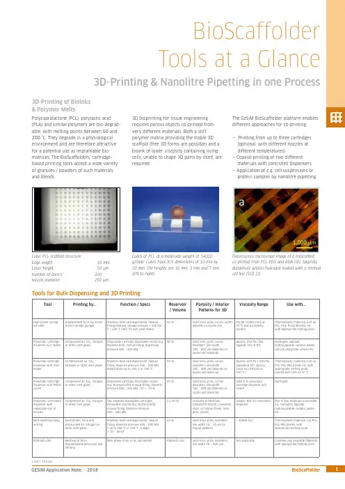
ToolPrinting by...Function / SpecsReservoir / VolumePorosity / InteriorPatterns for 3DViscosity Range Use with...High-power syringe extruder Displacement force by motor-driven syringe plungerStainless steel cartridge/nozzle; manual lling/cleaning, dosage pressure > 100 bar, T < 250 °C (482 °F), two-zone heater 10 mlSolid lines, grids, curves; width depends on nozzle sizePCL80 (12600 Pa·s) at 70 °C was succesfully printed Thermoplastic materials such asPCL, PLA, PLGA (blends), etc. with appropriate melting pointPneumatic cartridgedispenser w/o heater Compressed air, CO₂, nitrogen or other inert gasesDisposable cartridge, disposable nozzle (e.g Nordson EFD); manual lling, dispensing pressure 500 … 600 kPa30 ml Solid lines, grids, curves, meanders; line width100 … 400 µm (depends on nozzle and material)Approx. 550 Pa·s (Na-alginate 16% at RT)Hydrogels, alginate,hydroxyapatite, ceramic pastes,calcium phosphate cement etc.Pneumatic cartridge dispenser with shell heaterCompmressed air, CO₂,nitrogen or other inert gasesStainless steel cartridge/nozzle; manual lling, dispense pressure 500 … 600 kPa, temperature up to 100 °C or 190 °C10 mlSolid lines, grids, curves, meanders; line width100 … 400 µm (depends on nozzle and material)Approx. 550 Pa·s (16% Na-alginate at RT), approx. 1350 Pa·s (PCL50 at 100 °C)Thermoplastic materials such as PCL, PCL-PEG blends etc. with appropriate melting point, bioinks with cells at 37 °C Pneumatic cartridge dispenser with Peltier cooler Compressed air, CO₂, nitrogen or other inert gases Disposable cartridge, disposable nozzle (e.g. Nordson EFD); manual lling, dispense pressure 500 … 600 kPa, ΔT ≈ –20 K10 mlSolid lines, grids, curves, meanders; line width100 … 400 µm (depends on nozzle and material)Similar to pneumatic cartridge dispenser w/o heaterHydrogelsPneumatic core/shelll dispenser with replacable pair of nozzlesCompressed air, CO₂, nitrogen or other inert gasesTwo separate disposable cartridges, disposable nozzles (E.g. Nordson EFD); manual lling, dispense pressure 500 … 600 kPa2 x 10 mlCoaxially printed two-component strands (…macaroni style“ or hollow bres), lines, grids, curvesSmaller than for pneumatic dispenserPair of two materials (core/shell), e.g. hydrogels, alginate,hydroxyapatite, ceramic pastes etc.Melt electrospinning writingElectrostatic force andpressurized air, nitrogen or other inert gasesStainless steel cartridge/nozzle; manual lling, dispense pressure 500 … 600 kPa T up to 100 °C or 190 °C, voltage ± 10 … 30 kV10 ml Solid lines, grids, meanders; line width 10 … 20 µm for regular patterns> 10000 Pa·sThermoplastic materials, e.g. PCL, PCL-PEG blends, with appropriate melting pointFDM extruderMechanical force(displacement/extrusion) and meltingWire drawn from a coil and meltedFilament coilsSolid lines, grids, meanders; line width 70 (400)µmNot applicableCommercially available laments with appropriate melting pointBioScaffolder Tools at a Glance3D-Printing & Nanolitre Pipetting in one ProcessPolycaprolactone (PCL), polylactic acid (PLA) and similar polymers are bio-degrad-able, with melting points between 60 and 200 °C. They degrade in a physiological environment and are therefore attractive for a potential use as implantable bio-matrices. The BioScaffolders‘ cartridge-based printing tools accept a wide variety of granules / powders of such materials and blends.3D-Printing of BioInks & Polymer MeltsCubic PCL scaffold structure:Edge length: 10 mmLayer height: 50 µm Number of layers: 200Nozzle diameter:250 µmCubes of PCL at a molecular weight of 14000 g/mole. Cubes have X/Y dimensions of 10 mm by 10 mm. The heights are 10 mm, 3 mm and 7 mm (left to right).The GeSiM BioScaffolder platform enables different approaches for co-printing:— Printing from up to three cartridges (optional: with different nozzles at different temperatures)— Coaxial printing of two different materials with core/shell dispensers — Application of e.g. cell suspensions or protein samples by nanolitre pipetting3D bioprinting for tissue engineering requires porous objects co-printed from very different materials. Both a stiff polymer matrix providing the stable 3D scaffold (free 3D forms are possible) and a bioink of lower viscosity containing living cells, unable to shape 3D parts by itself, are required.Fluorescence microscope image of a bioscaffold co-printed from PCL-PEG and ADA-GEL (alginate dialdehyde gelatin hydrogel) loaded with a stromal cell line (St2) [1]Tools for Bulk Dispensing and 3D PrintingBioScaffolderTools at a GlanceTool Printing by...Function / Specs Reservoir/ VolumeInterior Patterns for3D ObjectsViscosity Range Use with...Piezoelectric pipette(optionally heatable)or Twin-TipUltrasonic wave; Twin-Tippipette allows kinetic mixingPipettor(s) with wash system, drop-on-demand dispensing, single drop volume100 … 400 picolitres, automatic ll-up,T < 100 °C96 well microtitreplate, max.120 µl/wellSingle spots of at least 80 µm,arrays, linesUp to 10 mPa·s All líquid samples, e.g. proteinsolutions, cell suspensions,solved polymers (two-componentsystems)Solenoid valvepipetteSolenoid valve andpressurized airPipettor with wash system, drop-on-demand dispensing, single pulse60 nanolitres, range up to microlitres,automatic ll-up96 well microtitreplate, max.120 µl/wellSingle spots, arrays, lines Up to 40 mPa·s All líquid samples, e.g. proteinsolutions, cell suspensions,dissolved polymersPassive pipette tips(Metal/Te on-coated)Diluter syringe displacement Pipettor with wash system, µl range,automatic ll-up96 well microtitreplate, max.120 µl/wellBulk dispensing of ml volumeson printed patternsLiquids (depends on tipsize)All liquid samples, e.g. proteinsolutions, cell suspensions,dissolved polymersPiezoelectricdispense valves (OEMcomponents)Piezoelectric valve andpressurized airCartridge dispenser, drop-on-demanddispensing, drop volume in the nanolitrerange (also heatable)3 ml Single spots, arrays, lines Approx. 50 … 200.000mPa·sHighly viscous liquids, e.g. glue,dissolved polymersPowder pipette Vacuum, compressed air Aspiration / dispensing of powder aliquotsin the µg rangemin. 1 ml Spots Solid materials Granular materials and powderReferences:[1] Tobias Zehnder, Tim Freund, Merve Demir, Rainer Detsch, Aldo R. Boccaccini: Fabrication of cell-loaded two-phase 3D constructs for tissue engineering, Materials 2016, 9, 887(Institute of Biomaterials, Department of Materials Science and Engineering, University of Erlangen-Nürnberg, Germany)[2] Stefan Giron, Anja Lode, Michael Gelinsky: In situ functionalization of scaffolds during extrusion-based 3D plotting using a piezoelectric nanoliter pipette, J. 3D Print. Med., 2017, 1,25 (Centre for Translational Bone, Joint & Soft Tissue Research, University Hospital Carl Gustav Carus & Faculty of Medicine, TU Dresden, Germany)Melt Electrospinning WritingThe Melt Electrospinning Writing Module(MES) uses electrical charge to draw verythin bres, typically in the micrometrerange, from a liquid or polymer melt.Depending on the experimental set-up,arbitrary and regular patterns can begenerated.The MES module for the BS3.x contains ahigh-voltage generator and a specialsubstrate support. Special dispense nozzlesand metal cartridges are required.The spun scaffold consists of stacked layers, eachrotated at 30 degrees. Printing was done withPCL 14,000 at 100 °C and 10 kV.SEM image, PCL 14,000, 15 kV, 100 °C, strutwidth is between 20 and 40 µmNanolitre PipettingThe pipetting module enables the partialfunctionalization of 3D-printed structuresby applying nanolitre amounts of cellsuspensions or protein solutions.Alternatively, micro-scaffolds from curableliquid samples are feasible.On the right: Fluorescein-labelled dots (green)printed at de ned XY positions on a scaffold thatwas printed from oil-based CPC (calcium-phoshatecement) paste [2]Tools for Liquid and Powder PipettingBottom layer with 20 µm strands, top layer with100 µm strandsOmniCure S1500: 200 W mercury UV lamp with selectable lters covering wavelengthsfrom 250 nm to 500 nm. Typical irradiation is in the range of 6 ... 28 W/cm².Camera with a wide range of lenses at different magni cationsOptical (OEM) Components。
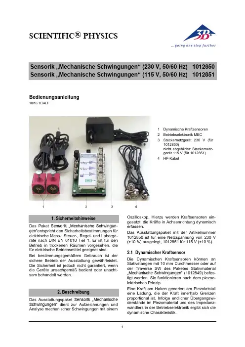
SCIENTIFIC ® PHYSICS1Bedienungsanleitung10/16 TL/ALF1 Dynamische Kraftsensoren2 Betriebselektronik MEC3 Steckernetzgerät 230 V(für1012850)nicht abgebildet: Steckernetz-gerät 115 V (für 1012851) 4 HF-KabelDas Paket Sensorik …Mechanische Schwingun-gen“entspricht den Sicherheitsbestimmungen für elektrische Mess-, Steuer-, Regel- und Laborge-räte nach DIN EN 61010 Teil 1. Er ist für den Betrieb in trockenen Räumen vorgesehen, die für elektrische Betriebsmittel geeignet sind.Bei bestimmungsgemäßem Gebrauch ist der sichere Betrieb der Ausstattung gewährleistet. Die Sicherheit ist jedoch nicht garantiert, wenndie Geräte unsachgemäß bedient oder unacht-sam behandelt werden. Das Ausstattungspaket Sensorik …Mechanische Schwingungen“ dient zur Aufzeichnungen und Analyse mechanischer Schwingungen mit einemOszilloskop. Hierzu werden Kraftsensoren ein-gesetzt, die Kräfte in Achsenrichtung dynamisch erfassen.Das Ausstattungspaket mit der Artikelnummer 1012850 ist für eine Netzspannung von 230 V (±10 %) ausgelegt, 1012851 für 115 V (±10 %).2.1 Dynamischer KraftsensorDie Dynamischen Kraftsensoren können an Stativstangen mit 10 mm Durchmesser oder auf der Traverse SW des Paketes Stativmaterial …Mechanische Schwingungen“ (1012849) befes-tigt werden. Sie funktionieren nach dem piezoe-lektrischen Prinzip.Eine Kraft am Haken generiert am Piezokristall eine Ladung, die der Kraft innerhalb Grenzen proportional ist. Infolge endlicher Übergangswi-derstände im Piezomaterial und des Impedanz-wandlers in der Betriebselektronik ergibt sich die dynamische Charakteristik.2Montage der dynamischen Kraftsensoren Die Montage der Sensoren ist für das Paket Sta-tivmaterial …Mechanische Schwingungen“ (1012849) optimiert (siehe Bedienungsanleitung-en der weiter unten genannten Pendel).Darüber hinaus können die Sensoren mittels Rändelschraube an Blechen oder Stäben mit 10 mm Durchmesser befestigt werden.Achtung! Die dynamischen Kraftsensoren dür-fen nicht mechanisch überlastet werden!∙ Den Krafthaken in axialer Richtung nicht mitmehr als 5 N und in Querrichtung nicht mit mehr als 1 N belasten.∙ Besonders bei der Montage und beim Ein-hängen von Schlaufen oder Federn am Krafthaken auf die maximal zulässigen Kräf-te achten.2.2 Betriebselektronik MECFig. 1 Betriebselektronik MEC 1a Anschluss für Steckernetzgerät1b Eingänge A und B für Dynamische Kraftsensor 1c Ausgänge A und B für Dynamische Kraftsensor 1d Ausgang ΔφAB für PhasendetektorVerstärkerkanäleIm Zusammenhang mit den Dynamischen Kraft-sensoren werden die Verstärkerkanäle A und B derBetriebselektronik MEC genutzt. Dort wer-den die Signale beider Kraftsensoren zur Dar-stellung mit einem Oszilloskop oder anderen Anzeigegeräten aufbereitet und hochohmig aus-geführt. Zusätzlich wird die Phasenlage zwischen beiden Signalen ausgewertet und als Gleich-spannungssignal ausgegeben. Die übrigen Ein- und Ausgänge haben hier keine Funktion.PhasendetektorEin Phasendetektor vergleicht die zeitlichen Verläufe der Signale A und B. In Abhängigkeit von der Phasendifferenz ΔφAB zwischen A und B liefert der Ausgang ΔφAB Gleichspannungswerte zwischen -8 V (∆φ = 0°) und +8 V (∆φ = 180°). 2 Dynamische Kraftsensoren 2 HF-Kabel1 Betriebselektronik MEC 1 Steckernetzgerät 12 V AC Dynamischer Kraftsensor Maximale Kraft in axialer Richtung: 5 N in radialer Richtung: 1 N Untere Grenzfrequenz: 0,2 Hz Anschluss: Klinkenstecker 3,5 mm Kabellänge 0,8 m Abmessungen: ca. 52 x 37 x 26 mm³ Masse: ca. 80 gBetriebselektronikSpannungsversorgung: über Steckernetzgerät Eingangsbuchsen: Klinkenbuchse 3,5 mm Ausgangsbuchsen: BNC Verstärker A, B: Ausgang ±8 V,Ri = 100 M Ω Ra = 1 kΩPhasendetektor XOR: Ausgang ±8 V,Ra = 1 kΩAbmessungen: ca. 65 x 100 x 40 mm³Steckernetzgerät für 1012850 Primärseite: 230 V, 50/60 Hz Sekundärseite: 12 V AC; 700 mASteckernetzgerät für 1012851 Primärseite: 115 V, 50/60 Hz Sekundärseite: 12 V AC; 500 mA∙ Betriebselektronik MEC nur mit dem mitge-lieferten Steckernetzgerät 12 V AC betrei-ben.3B Scientific GmbH ▪ Rudorffweg 8 ▪ 21031 Hamburg ▪ Deutschland ▪ Technische Änderungen vorbehalten © Copyright 2016 3B Scientific GmbHZur Durchführung von Experimenten zu mecha-nischen Schwingungen sind die nachfolgenden Ausstattungen empfehlenswert. Hier wird durch den Einsatz eines USB-Oszilloskops erreicht, dass die Schwingungen mit der Oszilloskop-Software auf einem PC analysiert und ausgewer-tet werden können.Alternativ kann jedes beliebige Oszilloskop eing-esetzt werden.5.1 Wilberforce-Pendel1 Ergänzungssatz …Wilb erforce-Pendel“ 1012844 1 Stativmaterial …Mechanische Schwingungen“ 1012849 1 Sensorik …Mechanische Schwingungen“ @230V 1012850 oder @115V 1012851 1 USB-Oszilloskop 2x50 MHz 1017264 1 PC, Betriebssystem Win XP, Vista, Win 7 oder1 Analog Oszilloskop 2x 30 MHz 10027275.2 Physikalisches Pendel1 Ergänzungssatz …Physikalisches Pendel“ 1012853 1 Stativmaterial …Mechanische Schwingungen“ 1012849 1 Sensorik …Mechanische Schwingungen“ @230V 1012850 oder @115V 1012851 1 USB-Oszilloskop 2x50 MHz 1017264 1 PC, Betriebssystem Win XP, Vista, Win 7 oder1 Analog Oszilloskop 2x 30 MHz 10027275.3 Faden-Pendel1 Ergänzungssatz …Fadenpendel“10128541 Stativmaterial …Mechanische Schwingungen“ 1012849 1 Sensorik …Mechanische Schwingungen“ @230V 1012850 oder @115V 1012851 1 USB-Oszilloskop 2x50 MHz 1017264 1 PC, Betriebssystem Win XP, Vista, Win 7 oder1 Analog Oszilloskop 2x 30 MHz 1002727∙ Die Verpackung ist bei den örtlichen Recyc-lingstellen zu entsorgen. ∙Sofern das Gerät selbst verschrottet werden soll, so gehört dieses nicht in den normalen Hausmüll. Bei Nutzung in Privat-haushalten kann es bei den örtlichen öf-fentlich-rechtlichen Entsorgungsträgernentsorgt werden.∙ Geltende Vorschriften zur Entsorgung von Elektroschrott einhalten.。

三维扫描仪操作指导书工程训练中心工程综合训练部前言近年来,随着制造技术的飞速开展,一种新的制造概念改变了以前传统制造业的工艺过程。
这种新的制造思路是:首先对现有的产品模型进展实测,获得物体的三维轮廓数据信息,再进展数据重构,建立其CAD数据模型。
设计人员可在CAD模型上再进展改良和创新设计,最后获得的数据可直接输入到快速成型系统或者形成加工代码输入到数控加工中心,生成新的产品或其模具,最后通过实验验证,产品定型后再投入批量生产。
这一过程就被称为反求工程,它使产品的设计开发的周期大为缩短,其整个过程可用如下图描述。
反求工程系统可分为三局部:即数据的获取与处理系统;数据文件自动生成系统;自动加工成型系统。
其中物体三维轮廓数据的准确获取是整个反求工程的关键所在。
我们将要介绍的三维扫描仪就是用于物体三维轮廓数据的获取,它具有精度高,速度快,对工件无磨损,无接触变形,易装夹,易操作等优点,可广泛应用于汽车、电子通讯、玩具、制造行业。
第一章系统简介X H A3D三维扫描系统特点XHA3D三维扫描系统采用世界领先的光栅式照相技术,在短时间获取物体外表三维数据,广泛应用于模具设计、逆向工程、质量检测和控制、医学测量等领域,产品主要具有以下特点:扫描速度与精度的完美结合单面扫描时间少于10 秒;采用全自动拼接技术,拼接精度可达0.04mm/m。
非接触式扫描采用非接触光栅式照相扫描技术,防止了因扫描头磨损而影响精度,具有很高的稳定性。
适用于橡胶类、皮革类等外表易变形物体扫描。
操作简便操作界面简洁明了,初学者易上手,短时间可熟练操作。
采用安全的结构光光源ZRET系列三维扫描仪采用安全的结构光光源,对人体无伤害,对环境要求不敏感,不需要在暗室中操作。
全自动拼接运用标志点拼接技术,扫描过程中不用人为干预,对大型物体屡次拍摄,对复杂物体多角度扫描,可得到完整、准确的三维点云数据。
精细拼接采用独特的ICP(Iterative Closest Point)技术,将扫描所得数据的公共局部中所有点进展最优匹配运算,该算法拼合精度高、运算速度快,使工件的整体误差控制在一定围,解决了拼接过程中可能会出现的分层问题。
Industrial 3D Measurement SolutionHSCAN 3D SCANNERContentpany introduction (1)2.Product introduction (1)2.1 Overview (1)2.2 Principle (2)2.3 Feature (2)2.4 Parameter (3)2.5 Application (4)3.Configuration (4)4.Customer Support (5)4.1 Training (5)4.2 Maintance (5)5.Application case (6)5.1 Car design (6)5.2 Car interior (7)5.3 Casting molding (8)5.4 Aerospace (9)5.5 Rail transportation (10)5.6 Furniture (11)5.7 Heritage sculpture (12)HSCAN331 3D Scanner Technical Proposalpany introductionHangzhou Scantech Co., Ltd is a high-tech enterprise specialized in the development, manufacture and sale of intelligent visual inspection equipment. As one of the most professional 3D digital equipment supplier, Scantech has been granted and assigned a number of technological patents.R&D team developed series of 3D digital equipment with self-owned intellectual property rights such as handheld laser 3D scanner, Tracking 3D scanner and global photogrammetry system and so on. Especially PRINCE series with capability of capture extreme detail and AXE series with high volumetric accuracy are global creative initiative, and gain great attention and recognition in the 3D digital field. Furthermore, R&D team establish joint development center with Norway Metronor which is a well-known optical metrology enterprise in Europe.2.Product introduction2.1 OverviewHSCAN series adopts multiple beam lasers to obtain 3D point cloud from object surface.The operator can hold the device on hand and adjust the distance and angle. It can cooperate with the photography measurement system (MSCAN) when scanning the large piece object to eliminate the accumulated error and improve the volumetric accuracy.The scanner can be conveniently carried to industrial onsite or production workshop, and do the accurate scanning according to size and shape of object.2.2 Principle1) Two sets of cameras on the scanner can respectively obtain the projection laser from scanned object, this laser will deform when scanner moving on the object surface, then we can calculate the linear 3D information from the laser as the distance between two cameras is accurately calibrated in advance.2) Device identify the spatial position according to the visual marker on scanned object surface when scanning, which is used for spatial position conversion.3) The 3D position information where the laser goes through can be acquired by utilizing the linear 3D information and relative spatial position when scanner moves, thus form the continuous 3D information.2.3 FeatureHigh precision-accuracy is up to 0.03mm to ensure accurate data for 3D measurementSelf-position- no need for extra position deviceDynamic measurement-secure full freedom between scanner and scanned objectReal-time visualization-Point cloud without layering, automatically generate 3D solid graphics (triangular mesh)Anti-interference-accuracy is insensitive to unstable environment, work normally in direct sunlight High adaptability-easily deal with shining or black surface, mostly imaging enhancement is unnecessary. Wide application-easy to scan different shape of object from egg size to planeEasy operation-handheld measurement-use in narrow space such as cockpit and car interior dashboard and so on-easy carrying with less than 1kg weightVoice reminding-ensure to operate at best working arrangeLong distance work-support long distance work with Gigabit Lan2.4 ParameterChart1 HSCAN331 technical parameterType HSCAN331Weight0.95kgDimension315*165*105mmLaser source 3 red laser crosses (+1 extra red laser)Scan deep hole support Hyperfine scan supportSmall piece matching Sticker on each side when scanning on small thin object, thenmatch together easilyMeasurement rate265,000 measures/s Scan area 225mm×250mmLaser classⅡ(eye safe)Resolution0.05mmAccuracy Up to 0.03mm Volumetric accuracy 0.02mm+0.08mm/m Volumetric accuracy(with MSCAN)0.02mm+0.025mm/m Stand-off distance300mmDepth of field250mmOutput format. ply、.xyz、.dae、.fbx、.ma、.obj、.asc、.stl or customized Work temperature-10~40℃Interface mode Gigabit LanRapid calibration Complete calibration within 60sPC requirementsCPU:i7-6820HQRAM:32G,2133MHzDDR4 GPU:NVIDIA Quadro M1000M 2GB GDDR5 Operating system:Windows 7-64 bit, Windows 82.5 Application➢Automobile manufacturing➢Aerospace➢Power generation➢Model manufacturing➢Casting inspection➢Construction machinery➢Design inspection➢Architecture sculpture➢Colleges and research institutes3.ConfigurationThe production capacity of portable 3D scanner is about 300 to 400 sets per year. The accessories are adequate and can deal with the emergency situation.Chart2. HSCAN standard configurationComponent Quantity3D scanner 1Calibration plate1Combination cable1Power adapter16mm reflective marker4000Waterproof case1scan software14.Customer Support4.1 TrainingOur goal is to develop skills by providing flexible training according to participants’ level of knowledge.To ensure training quality and consistency, our team of experienced trainer draw on training plans with other tools to clearly explain train objectives, introduce theory, guide hands-on practice and assess student progress.4.2 MaintanceScantech offer multilingual service and support to ensure satisfactory solution.We promise 1-year warranty after sale. Take advantage of worry-free maintance and global repair coverage for all of your hardware and software, we will have a plan suited to your needs while your device is on service time.5.Application case5.1 Car designRedesign carParts optimizeAssemle gap size analysis5.2 Car interiorDashboard optimizationLuggage durable test Window control table optimize5.3 Casting moldingSmall casting reverse engineering Small cylinder cover redesignCAD to parts5.4 AerospacePlane reverse engineering Wing 3D inspection5.5 Rail transportationSubway 3D inspection5.6 FurnitureWood carved chair modeling Sofa 3D reconstruction5.7 Heritage sculpturePalaeobios 3D remodelingBuddha 3D remodelingFor more info: 。
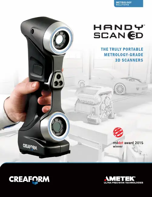
THE TRULY PORTABLE METROLOGY-GRADE3D SCANNERSThe HandySCAN 3D TM handheld scanners of new &UHDIRUP·V ÁThe easiest 3D scanning experience,generating fast and reliablemeasurements.The most accurate scanning and probing solutions, whether in a lab oron the shop floor.The truly portable metrology-grade 3D scanners delivering highly accuratemeasurements.CREAFORM 3D SCANNERSACCURACY. PORTABILITY. SIMPLICITY.THE HANDYSCAN 3D SCANNERS : YOUR BEST ALLY AT ALL STAGESOF YOUR PRODUCT LIFECYCLE MANAGEMENT–C–M–M–C–M– S–I ntegration of prototypePRGLÀFDWLRQV LQWR &$' À OH – Form study, proof-of-concept prototypes–ErgonomyprototypesTesting, simulation and analysis–3D scan-to-CAD–R everse engineering (extracting design-intent) –P ackaging design–R apid prototyping/Manufacturing – ,QWHJUDWLRQ RI SURWRW\SH PRGLÀ FDWLRQV LQWR &$' À OH –P rototype inspection– F inite element analysis (FEA) –I nterference analysis – D eformation, geometry analysis Tooling design Assembly/Production Quality control– R À [WXUHV MLJV DQG SDWWHUQV – 8SGDWH RI &$' À OH WR UHÁ HFW DV EXLOW tooling measurements–T ooling validation/Inspection–V irtual assembly – T ool/Robot path programming – P art assessment before machining – F irst article inspection (FAI)–P art-to-CAD inspection – S upplier quality inspectionDocumentationMaintenance, repair andoverhaul (MRO)Replacement/Recycling– A s-built documentation of parts/Tooling – M systems, serious gaming –D igital archiving– W ear and tear analysis – &XVWRP UHSDLUV 0RGLÀ FDWLRQ – A s-built documentation of parts/Tooling before maintenance – R everse engineering for developing replacement/Restoration parts – P lanning of complex assemblies disassembly/DismantlingOTHER APPLICATIONSC R E A F O R M 3D S C A N N I N GALL OF THE CREAFORM PORTABLE 3D SCANNERS FEATURE INNOVATIVE AND EXCLUSIVE TECHNOLOGIES:TRUaccuracy TMACCURATE MEASUREMENTS IN REAL LIFE OPERATING CONDITIONSTRUportability TM 3D SCANNING WHERE YOU NEED TO GO TRUsimplicity TMOVERLY SIMPLE 3D SCANNING PROCESSAUTOMATIC MESH OUTPUT: READY-TO-USE FILES, RIGHT AS YOUCOMPLETE ACQUISITION.QUICK WORKFLOW INTEGRATION: USABLE SCAN FILES TO BEIMPORTED INTO RE/CAD SOFTWARE WITHOUT POST-PROCESSING.REAL-TIME VISUALIZATION: LOOK AT THE COMPUTER SCREENTO SEE WHAT YOU ARE DOING AND WHAT IS LEFT TO BE DONE.ON-THE-GO SCANNING: TAKE IT FROM PLACE TO PLACE ORUSE IT IN-HOUSE OR ON SITE.LIGHTWEIGHT AND SMALL: WEIGHTS 0.85 kg (1.9 lb.), CANREACH CONFINED AREAS. FITS INTO A CARRY-ON.QUICK SET-UP: UP AND RUNNING IN LESS THAN 2 MINUTES.NO RIGID SETUP REQUIRED: THE PARTAND SCANNER CAN BE MOVED FREELY DURING SCANNING.SELF-POSITIONING: ITUSES TRIANGULATION ON OPTICAL REFLECTORS TO DETERMINE ITS RELATIVE POSITION TO THE PART.STAND-ALONE DEVICE: NO EXTERNAL POSITIONING SYSTEM, NOARMS, NO TRIPOD OR FIXTURE.FASTEST 3D SCANNER ON THE MARKET: 25 TIMES FASTER THANTHE PREVIOUS GENERATION.HIGHEST MEASUREMENT RATE AMONG ALL LASER SCANNERS:480,000 MEASURES/SVERSATILE: VIRTUALLYLIMITLESS 3D SCANNING – NO MATTER THE PART SIZE, COMPLEXITY, MATERIAL OR COLOR.USER-FRIENDLY: VERYSHORT LEARNING CURVE, REGARDLESS OF THE USER’S EXPERIENCE LEVEL.METROLOGY-GRADE MEASUREMENTS:ACCURACY OF UP TO 0.030 mm (0.0012 in.), RESOLUTION OF UP TO 0.050 mm (0.002 in.), HIGH REPEATABILITY AND TRACEABLE CERTIFICATE.–U ser-friendly interface: VXelementswas designed to simplify the wholescanning process to its essential core,through a powerful and simple process;–S urface optimization algorithm: avoidsthe creation of multiple scan layers andensures a more accurate mesh withoutany post-treatment;–D irect mesh output: an optimized meshcan be exported in all standard formats,right as you complete acquisition. Nocomplicated alignment or point cloudprocessing needed;–N o limitation to the scan resolution:you simply need to input a resolutionvalue, independent from the size ofWKH VFDQQHG REMHFW 5HVROXWLRQ FDQ EHchanged at any time before/after thescan;–R eal-time visualization: the user canYLHZ WKH ' VXUIDFH DV WKH REMHFW LV EHLQJscanned;–S can results enhancement: KROH À OOLQJVPDUW GHFLPDWLRQ ERXQGDU\ À OWHUV HWF VXELEMENTS TM : CREAFORM’S3D SOFTWARE PLATFORMHHW RI 'HOHPHQWV DQG WRROV LQWR D XVHU IULHQGO\ VLPSOLÀ HG DQG VOHHN ZRUNLQJ environment. Its real-time visualization provides a simple, enjoyable scanning experience.$Q RSWLPL]HG VFDQ À OH LV DXWRPDWLFDOO\ FUHDWHG DQG DYDLODEOH XSRQ completion of the data acquisition step, which contributes to greatly shorten your part inspection or design process.EXTEND THE POWER OF YOUR HANDYSCAN 3D SCANNERACCESSORIESCREAFORMCUSTOMER SERVICEWhen you purchase a Creaform 3Dmeasurement solution, you can rely on the CreaCare TM customer service program. We find it important to help you simplify your work, increase your efficiency and make the most out of your Creaform device.You want to make sure to start things right? For a small fee, you can ask that a qualified expert comes over to your business place to help you get started with your system, and to train your staff on your specific applications.Of course, we offer you readily available, multilingual technical support on all continents, ensured by knowledgeable, proactive and committed product specialists.To protect your investment further and keep you on the technological edge, you can also subscribe to a CreaCare Maintenance Plan, offered in various protection packages. Depending on the package selected, you could get instant downloading access to each new release of our proprietary data acquisition software or get a free loaner unit while your device gets serviced, for instance.CREAFORMMETROLOGY AND 3D ENGINEERING SERVICESConvinced of the quality and possibilities of the Creaform technologies, but not quite yet ready to commit and buy? Know thatCreaform offers a wide range of metrology and 3D engineering services. Our experts have earned a worldwide reputation foreffectiveness and professionalism. Whether you need their help to perform 3D scanning, quality control, reverse engineering, FEA/CFD simulations, product and tooldevelopment or training services, you can count on their commitment to meet your requirements with responsiveness and adaptability.Authorized DistributorHandySCAN 3D, HandySCAN 300, HandySCAN 700, Go!SCAN 3D, MetraSCAN 3D, TRUaccuracy, TRUportability, TRUsimplicity , VXelements, MaxSHOT 3D, VXmodel, VXremote, CreaCare and their respective logo are trademarks of Creaform Inc. © Creaform inc. 2015. All rights reserved. V2TECHNICAL SPECIFICATIONSHandySCAN 300TMHandySCAN 700TMWEIGHT 0.85 kg (1.9 lb.)DIMENSIONS77 x 122 x 294 mm (3.0 x 4.8 x 11.6 in.)MEASUREMENT RATE205,000 measurements/s480,000 measurements/sSCANNING AREA 225 x 250 mm (8.8 x 9.8 in.)275 x 250 mm (10.8 x 9.8 in.)LIGHT SOURCE 3 laser crosses7 laser crosses (+1 extra line)LASER CLASS 2M (eye-safe)RESOLUTION 0.100 mm (0.0039 in.)0.050 mm (0.0020 in.)ACCURACYUp to 0.040 mm (0.0016 in.)Up to 0.030 mm (0.0012 in.)VOLUMETRIC ACCURACY*0.020 mm + 0.100 mm/m (0.0008 in. + 0.0012 in./ft)0.020 mm + 0.060 mm/m (0.0008 in. + 0.0007 in./ft)VOLUMETRIC ACCURACY (WITH MAXSHOT 3D)*0.020 mm + 0.025 mm/m (0.0008 in. + 0.0003 in./ft)STAND-OFF DISTANCE300 mm (11.8 in.)DEPTH OF FIELD250 mm (9.8 in.)PART SIZE RANGE (RECOMMENDED)0.1 – 4 m (0.3 – 13 ft)SOFTWAREVXelementsOUTPUT FORMATS .dae, .fbx, .ma, .obj, .ply, .stl, .txt, .wrl, .x3d, .x3dz, .zprCOMPATIBLE SOFTWARE 3D Systems (Geomagic® Solutions), InnovMetric Software (PolyWorks), Dassault Systèmes (CATIA V5 and SolidWorks), PTC (Pro/ENGINEER), Siemens (NX andSolid Edge), Autodesk (Inventor, Alias, 3ds Max, Maya, Softimage).CONNECTION STANDARD1 X USB 3.0OPERATING TEMPERATURE RANGE5-40 °C (41-104 °F)OPERATING HUMIDITY RANGE (NON-CONDENSING)10-90%%DVHG RQ WKH ,62 VWDQGDUG YROXPHWULF DFFXUDF\ LV GHÀQHG DV D VL]H GHSHQGHQW YDOXH&UHDIRUP LQF +HDG 2IÀFH5825 rue St. GeorgesLévis, Québec G6V 4L2 Canada Tel.: 1.418.833.4446Fax: 1.418.833.9588*******************|Creaform U.S.A. Inc.1590 Corporate DriveCosta Mesa CA 92626 USATel.: 1.855.939.4446 | Fax: 1.418.833.9588。
Features included in i-SolutionInclude:Live Measurement and Overlay SettingsUsers can perform measurements on the live preview image, using the crosshair or grid masks to center and count. The grid masks include calibration data. Calibration marker (scale bar) can be placed on the live preview image. The marker (scale bar) can also be burned on each captured image automatically. Anystandard file format image can be chosen to see it above live preview image.Calibration (Auto, Manual)All measurements start with an accurate calibration. Auto, Semi-Auto calibration functions allow the software to calculate the pixels-per-unit value automatically. Only setting the unit for the calibration scale and the distance between the scale marks is needed. This feature greatly improves the accuracy and repetition of measurements. Manual calibrations are easily added and saved for recall from a drop down menu. All calibrations can be saved as files, which let the calibration be retrieved by simply opening the saved files later.Calibration can be protected by password option. Two password options, one in calibration menu itself and the other in camera resolution option, protect calibration by unexpected change. A scale bar can be permanently added to each image. Scale bar properties for color, size and text are simple to optimize for any image background.Z-Axis Extended Focus Imaging (EFI), with displacement compensation for stereo microscopesSamples with curves or of varying heights are difficult to bring into focus under highly magnified conditions. And more a stereomicroscope takes images with tilting due to its own structural characteristics. Thus, each image is out of its supposed position when you move microscope to the Z-axis getting the right focus. Our displacement compensation function allows you to rearrange these images automatically and manually.Software can combine a stack of images sequentially captured at different levels of focus and combine them into a single in-focus image. You can count on our software not to leave any trace of the composites.3D Visualization. . . clearly view complex structuresA Three-dimensional picture can be created from any image. The 3-D presentation is based upon intensity values of the image and can be displayed as a normal or wire frame image. Z axis information can easily be adjusted to optimize the 3-D effect. To better visualize an image in 3-D, software offers full 360 degrees of rotation on X-Y-Z axis. A 3D image can then saved in JPG, TIF or BMP format.Image Stitching. . . create a mosaic of the “Big Picture”With our software, you can create auto and manual composites of continuously captured images in order to minimize the reduction in the field-of-view that typically comes with increased magnification. Combined images are automatically corrected for brightness without leaving any stitching mark. Live Image Comparison. . . for fast inspection and size verificationFor QA testing or quick go/no-go inspections any stored image can be used as a reference image onto which the live preview image is projected.Time Lapse Capture and Movie File Production. . . Import into Power PointSoftware features a Time Lapse Capture function that supports TIF, BMP and JPG file formats. The Time Lapse Capture function also includes an Auto Save feature byyyyy/mm/dd/hour/minute/second. You can save video movie recordings in AVI, MPG, MPEG, and MOV formats.Combine Image Planes - Fluorescence ImagingMerge and pseudo color monochrome images into a single RGB composite.Advanced - Fluorescence Image mergeFluorescence merging function allows several images to one composite image.There is rich list of pre-defined dyes already.One can choose desired emission wavelength in nanometers also and then correspondent color is calculated automaticallyExport Into Excel® - with one mouse clickA single mouse click exports the original image with measurement, calibration, annotation overlay, measurement data, statistics, and chart.Manual Measurement Tools - Including Various Perpendicular DistanceSoftware’s versatile manual measurement features include tools for measuring lengths, areas, and angles and can even auto detect an object's outline and then make specified measurements. The software is equipped with a wide choice of powerful measurement tools including 3-point circle functionality, Npoint circle measurement functionality, parallel line distance measurement, perpendicular distance measurement and object distance measurement. In addition, a zoom-in window can be used to determine the accurate measuring point of an object.Once you've measured a specimen you can easily export all of the images, measurement data and statistics to an Excel® file. With i-Solution, comprehensive statistics and data are just one effortless mouse click away.Line ProfilingSingle, multiple, parallel and polyline commands provide Gray/Red/Green/Blue intensity values for specific lines within an image. The profile data of each pixel on the line can be exported to MS Excel. Auto TraceUsing an automatic edge detection algorithm, our software will perform an auto trace measurement function around a closed object. This function greatly increases accuracy and saves time when makingmeasurements of complex shapes.Image ProcessingManual Brightness, Contrast, Gamma, Background Subtraction, Shading Correction, Histogram, Clone, Crop, AOI, Resize, Rotate, Split, Merge Monochrome series into RGB Color, Combine different exposure Images for highlight reduction, Image Mode Change, Grayscale, RGB, HSB, YUV Pseudo Color view, Full range of enhancement and morphology filters 8bit and 16bit per channel Manual MeasurementsPoint Count, Straight Line, Circle by radius, Circle by N points, Circle by diameter, Circle by 3 points, rectangle, polygon, polyline, splice lines from a common point, auto trace, angle parallel lines, perpendicular width, perpendicular from common line, angle between 2 lines, distance, perpendicular distance.Shading CorrectionThe edge parts of captured image by low magnification have background shading frequently, which can be removed by the shading correction function. The color of the original image remains the same though. A standard image is acquired from a blank space on the slide glass, or from an out of focus image in a metallurgical specimen. Such a standard image is used to correct the background shading of all other captured images.AnnotationLine, arrow, polyline, spline, rectangle, ellipse, textRegion of Interest- ROI. . . . with unique add/subtract capabilityRectangle, arbitrary rectangle, circle, arbitrary ellipse, polyline, spline, magic wand ROI itself can be saved to work with other images. The saved ROI can be placed on the exact same location of other images.View and Zoom ImageManual zoom In-Out, User Defined, Fit to Window, 1600% Zoom in Window for Accurate Edge Detect, sizeable context Window to view all open ImagesImage EditingUndo, Redo, Copy, Paste, Paste New, Delete, Delete All, Annotate, Image InformationSave OptionsTXT File Format, image and measurement data together in Proprietary .img File Format for future editing and data collectionSupported Image File Formatsjpg, jpeg, tif, tiff, bmp, gif, pcx, tga, mpg, mpeg, avi, mov, img, rpt, txt and etc.Report GeneratorCreate Report, Insert Image and Data, Insert other OLE ObjectsWindow ViewSplit Horizontal, Split Vertical, Cascade, Tile Horizontal, Tile Vertical, Arrange icons, Dynamic User Interface (UI), Classic, ModernTime Lapse Sequence ControlPlay Forward, Backward, Making Movie File (mpg, avi, mov) with Still Images, Split Single Image from Sequence FileAuto/Manual Thresholding for Count and SizeIntensity and color based thresholding tools for identifying, counting and categorizing objects.Ideal for automatic objects counting and percentage of area measurements.Objects Editing… enhanced measurement accuracy!Target threshold objects can be edited by all measurement parameters or with filters to clean, close, open, dilate, erode, automatic separate and fill holes.Densitometryi-Solution software automatically calculates Optical Density (OD) by absolute and relative figures, semi automatically, or manually based on user configuration. Images and OD figures can then be exported directly to an MS PowerPoint file.Perfect Focus Enhancementi-Solution implements a perfect function of focus compensation irrespective of the status of lights and specimen.Macro-Enabled RecordingCreate and save customized measurement settings and sequencesData CollectorSelect desired measurements then easily collect and tabulate data from multiple samples. Reflected Light Subtractioni-Solution creates clear, evenly illuminated images by removing the bright saturated light from a highly reflective sample.Automatic count for live and stained cellsConglomerated live and stained cells are separated automatically and counted.Particle AnalysisParticle data in many images is given by statistics and individual form. Each object is viewed with data together.Phase Analysis & Advanced Thresholdi-Solution conducts phase analysis on an entire image or within a specified Region of Interest (ROI) and it can allow to sort images using Gray Scale, RGB, HSB or YUV.Thickness Measurement (Layer Depth Measurement)Average thickness is measured automatically by defining box. The number of scan lines can be defined by users.Stereometry for BiovolumeThe 3D volume of an object is calculated by using 2D measuring parameters.46 selectable measurement parametersA complete menu of measurement types with a description of the parameterIlluminator controlProgram controls illuminator shutter.Live cell countLive cells having irregular shape can be counted automatically, which can be hardly possible by ordinary thresholding method.System Requirements• PC with a Pentium-class processor; Pentium 300MMX or higher recommended• Microsoft Windows Win7/Vista/WinXP/2000/ME/Win98SE operating system• 32 MB of RAM or more (128 MB recommended)• 15 MB or more hard-disk space (50 MB recommended)• CD-ROM drive• VGA or higher-resolution monitor; Super VGA recommended (1024 x 768 pixel and 24 bit and more color support video card is recommended)• Microsoft Mouse or compatible pointing device• USB- or LPT-port for hardware key (depends on delivery).Supported imaging devices1. TWAIN Driver2. DirectShow/ WDM (Windows driver mode) driver3. i-Link DevicesAll PixeLINK cameras.Optronics digital cameras- MicroFire- MacroFire- QuantiFire and QuantiFire XI- Microcast- All MPX series cameras- All QPX series camerasJenoptik ProgRes digital cameras- C3 (cooled and non-cooled)- C5 (cooled and non-cooled)- C14- ProgRes CF and CFScan (cooled, non-cooled, and scan)- ProgRes MF (cooled, non-cooled, and scan)-ProgRes all CMOS cameras.Nikon digital cameras- DS-U2 Fi1- DS 5M/2M-U2- DS 5M/2M-U1- DXM 1200C- DXF 1200FPixera digital camera- Penguin series all models- Pro series all modelsScion corporation digital camera-CFW series all modelsMatrix vision-mvBlueFox digital cameraArtray- ARTCAM-500MI- ARTCAM-300MI- ARTCAM-200MI- ARTCAM-130MI (color, mono, and NIR)- ARTCAM-036MI (color, mono, and TWIN)- ARTCAM-500P- ARTCAM-200SH- ARTCAM-150P-II (color and mono)- ARTCAM-098 (color and mono)- ARTCAM-34MCLumenera- Infinity 1 series all models- Infinity 2 series all models- Infinity 3 series all models- Infinity X and Infinity X-21XLi camera- M series cameras- DC series cameras- DX series camerasSpot digital camera- Insight- FlexQimaging digital cameras- MicroPublisher- RetigaAll Leica digital cameras by TWAINCarl Zeiss AxioCam by TWAIN FlashBus frame grabber- Spectrim Lite- Spectrim Pro- MV LiteMatrox frame grabber- Meteor IIAvermedia frame grabber- EZMakerConsumer digital camerasIMT i-Solution Inc. 。
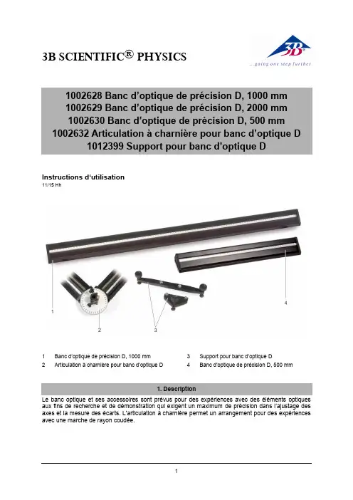
3B SCIENTIFIC ® PHYSICSInstructions d‘utilisation11/15 Hh1 Banc d’optique de précision D, 1000 mm2Articulation à charnière pour banc d’optique D3 Support pour banc d’optique D4Banc d’optique de précision D, 500 mmLe banc optique et ses accessoires sont prévus pour des expériences avec des éléments optiques aux fins de recherche et de démonstration qui exigent un maximum de précision dans l’ajustage des axes et la mesure des écarts. L’articulation à charnière permet un arrangement pour des expériences avec une marche de rayon coudée.2.1 Bancs optiquesLe banc optique est constitué d’un profilé tri-angulaire en aluminium anodisé noir, protégé contre tout basculement, résistant à la flexion et à la torsion, avec antiglissement. Des deux côtés se trouvent une graduation continue en cm/mm. Les surfaces d’appui présentent deux rainures permettant le logement optionnel de deux pieds ou d’un pied et d’un appui. A l’avant se trouvent trois perforations pour la fixation des plaques frontales ou de l’articulation à charnière.Illustration 1 Profilé triangulaire2.2 Jeu de pieds pour banc optiqueCe jeu compr end deux pieds de rail et d’un appui en aluminium anodisé noir. Il permet d’ajuster la hauteur du banc optique dans un appui à quatre ou trois points..Longueur des pieds: 270 mm Illustration 2 Pied de railIllustration 3 Appui2.3 Articulation à charnièreL’articulation est fabriquée en aluminium ano-disé noir et peut être orientée des deux côtés à 90°. Une graduation angulaire permet de rég-ler l’angle. L’axe pivotant comprend une co-lonne qui loge les éléments optiques.Angle de rotation: ± 90° Graduation angulaire: ±180°Pas: 1°Hauteur de colonne: 60 mm Etendue pour manches: 10 mm à 14 mmIllustration 4 Articulation à charnière3.1 Montage des pieds du rail∙Introduire les vis à tête carrée dans la rainure de guidage sous le rail profilé et les fixer en les serrant.∙Régler la hauteur avec la vis d’ajustage.∙Fixer la position avec la vis de blocage. 3.2 Montage de l’articulation à charnière∙Retirer la plaque frontale en desserrant les troisvis de fixation.∙Placer l’articulation à charnière sur le rail et la fixer avec les trois vis.∙Relier le second rail à l’articulation.3.3 Coulisseaux et aides de montagerecommandésPour le montage d’éléments dans l’axe op-tique:∙Cavaliers:Pour pivoter des éléments dans l’axe optique: ∙Cavalier pivotant D (1012467) Pour déplacer des éléments à la verticale de l’axe optique:∙Cavalier à déplacement latéral D (1002644)Pour positionner des éléments à côté de l’axe optique:∙Bras de rallonge D (1002646)。
maximum-power laser scanning power SCAN, power SCANiThe scan systems of the power SCAN series enable positioning multiple kilowatts of laser power onto a workpiece in just a few milliseconds. In combination with a vario SCAN, the laser beam can be dynamically focused within working volumes, thus allowing non-flat workpieces to be processed.Apertures from 33 mm up to 70 mm allow small spot sizes and therefore high power densities even with large working distances. The XY mirrors and the vario SCAN´s optics are air cooled, while the scanners, electronics and vario SCAN are water cooled. This ensures reliable operation with excellent long-term stability – even under challenging environmental conditions and with high laser powers. Each axis of the power SCAN 50, 50i, 70 and 70i is individually implemented as a sealed submodule – a calibrated and tuned unit containing a galvanometer scanner with a mirror and the scanner’s drive electronics. Thus, rapid replacement of individual axes is en-sured. Located in a separate sealed base module, the modularly-designed main electronics provide functions such as a digital interface and a power management system with comprehensive monitoring functions.The power SCAN i-series of scan systems employs the same i DRIVE ® electronic concept used in the success-proven intelli SCAN ®. This brings improved dynamics and advanced querying possibilities. The series includes both the power SCAN 50i and power SCAN 70i.Typical Applications:• Laser processing of materials• Rapid manufacturing• 3D applications• Processing-on-the-flySCANLAB America, Inc. · 100 Illinois St · St. Charles, IL 60174 · USA Tel. +1 (630) 797-2044 · F ax +1 (630) 797-2001info@ · Type-Dependent Specifications(all angles are in optical degrees)power SCAN 33power SCAN 50/50i power SCAN 70/70i Aperture33 mm 50 mm 70 mm Beam displacement 45.21 mm 72.72 mm 98.2 mmStep response time(settling to 1/1000 of full scale)1% of full scale 1.3 ms 1.5 ms / 2.0 ms (1) 2.8 ms / 3.5 ms (1)10% of full scale4.5 ms Typical processing speed 3 rad/s 2.5 rad/s1.5 rad/sTypical positioning speed 18 rad/s 15 rad/s / 25 rad/s (1)12 rad/s / 15 rad/s (1)Dynamic performance Tracking error0.75 ms0.9 ms1.6 msPower requirements±(15+1.5) V DC, max. 4.5 A each ±(24+1.5) V DC, max. 10 A each (20 A peak current)±(24+1.5) V DC, max. 10 A each (20 A peak current)Weight(with vario SCAN )12 kg33 kg35 kgTypical air requirementsclean, filtered air clean, filtered air clean, filtered air > 1.5 bar1.5 bar to2.0 bar1.5 bar to2.0 bar(1)the higher value applies to the power SCAN iCommon Specifications(all angles are in optical degrees)Dynamic performance Repeatability (RMS)< 4 µrad Long-term drift over 8 hours(after warm-up)< 0.6 mradOptical performance Typical scan angle ±0.35 rad Gain error < 5 mrad Zero offset < 5 mrad Skew< 1.5 mradNonlinearity < 2.1 mrad / 44°Input signals Analog version (not power SCAN i)alternatively: ±4.8 V; ±9.6 V; ±4.8 mA; ±9.6 mA Digital version • power SCANXY2-100 Standard,optionallyoptical data transfer • power SCAN iSL2-100Ouput signals 3 status signals per axisAnalog version (not power SCAN i)TTL levelDigital version • power SCANXY2-100 Standard,optionallyoptical data transfer • power SCAN iSL2-100Operating temperature 25 °C ± 10 °C Typical water requirementsmax. 4.5 barTypical Optical Configurationspower SCAN 33 with vario SCAN 40power SCAN 50/50i with vario SCAN 60/vario SCAN de 60iWavelength10.6 µm 10.6 µm 10.6 µm 10.6 µm 10.6 µm 10.6 µm 10.6 µm Max. laser power cwMax. laser power for 50% duty cycle2000 W 4000 W 2000 W 4000 W 2000 W 4000 W 2000 W 4000 W 2000 W 4000 W 2000 W 4000 W 2000 W 4000 W Image field size(170 x 170) mm 2(500 x 500) mm 2(1.5 x 1.5) m 2(400 x 400) mm 2(600 x 600) mm 2(800 x 800) mm 2(1.0 x 1.0) m 2Typical processing speed 0.8 m/s 2.0 m/s 6.0 m/s 1.3 m/s 2.0 m/s 2.7 m/s 3.2 m/s Focus range in z direction ±4 mm ±35 mm ±75 mm±10 mm±40 mm±50 mm±100 mmFocus diameter (1/e 2)210 µm (M 2=1)450 µm (M 2=1) 1.3 mm (M 2=1)250 µm (M 2=1)375 µm (M 2=1)500 µm (M 2=1)600 µm (M 2=1)Beam expansion factor 2.52.42.23.83.63.53.4Focal length(414 ± 15) mm(850 ± 75) mm(2300 ± 500) mm (750 ± 50) mm (1050 ± 90) mm(1350 ± 150) mm (1650 ± 250) mmpower SCAN 70/70i with vario SCAN 80/vario SCAN de 80iWavelength10.6 µm 10.6 µm 10.6 µm Max. laser power cwMax. laser power for 50% duty cycle 2000 W 4000 W 2000 W 4000 W 2000 W 4000 W Image field size(440 x 440) mm 2(1.0 x 1.0) m 2(1.6 x 1.6) m 2Typical processing speed 0.9 m/s 2.0 m/s 3.2 m/s Focus range in z direction ±10 mm ±75 mm ±200 mm Focus diameter (1/e 2)220 µm (M 2=1)450 µm (M 2=1)650 µm (M 2=1)Beam expansion factor 4.94.54.6Focal length(860 ± 45) mm(1680 ± 200) mm (2440 ± 400) mmSCANLAB AG · Siemensstr. 2a · 82178 Puchheim · Gemany Tel. +49 (89) 800 746-0 · F ax +49 (89) 800 746-199 info@scanlab.de · www.scanlab.de 12 / 2014 I n f o r m a t i o n i s s u b j e c t t o c h a n g e w i t h o u t n o t i c e . P r o d u c t p h o t o s a r e n o n -b i n d i n g a n d m a y s h o w c u s t o m i z e d f e a t u r e s .。