Journal of the European Ceramic Society xxx(2015)
xxx–xxx
Contents lists available at https://www.doczj.com/doc/b616234975.html,
Journal of the European Ceramic Society
j o u r n a l h o m e p a g e:w w w.e l s e v i e r.c o m/l o c a t e/j e u r c e r a m s o c
Review article
Modeling of thermal properties and failure of thermal barrier coatings
with the use of?nite element methods:A review
L.Wang a,b,?,D.C.Li a,b,c,J.S.Yang a,b,c,F.Shao a,b,X.H.Zhong a,b,H.Y.Zhao a,b,K.Yang a,b,
S.Y.Tao a,b,Y.Wang d
a Shanghai Institute of Ceramics,Chinese Academy of Sciences,Shanghai200050,PR China
b Key Laboratory of Inorgani
c Coating Materials,Chinese Academy of Sciences,Shanghai201899,PR China
c University of the Chinese Academy of Sciences,Beijing100039,PR China
d Laboratory of Nano Surfac
e Engineering,School o
f Materials Science and Engineering,Harbin Institute of Technology,Harbin150001PR China
a r t i c l e i n f o
Article history:
Received20August2015
Received in revised form
20December2015
Accepted25December2015
Available online xxx
Keywords:
Thermal barrier coatings
Finite element modeling(FEM)
Thermal insulation
Residual stress
Failure
a b s t r a c t
To understand the thermal insulation and failure problems of the thermal barrier coatings(TBCs)deeply
is vital to evaluate the reliability and durability of the TBCs.Actually,experimental methods can not
re?ect the real case of the TBCs during its fabrication and service process.Finite element modeling(FEM)
play an important role in studying these problems.Especially,FEM is very effective in calculating the
thermal insulation and the fracture failure problems of the TBCs.In this paper,the research progress of
the FEM on the study of the thermal insulation and associated failure problems of the TBCs has been
reviewed.Firstly,from the aspect of the investigation of the heat insulation of the TBCs,the thermal
analysis via FEM is widely used.The effective thermal conductivity,insulation temperature at different
temperatures of the coating surface considering the thermal conduct,convection between the coating
and the environment,heat radiation at high temperature and interfacial thermal resistance effect can
be calculated by FEM.Secondly,the residual stress which is induced in the process of plasma spraying
or caused by the thermal expansion coef?cient mismatch between the coating and substrate and the
temperature gradient variation under the actual service conditions can be also calculated via FEM.The
solution method is based on the thermal–mechanical coupled technique.Thirdly,the failure problems of
the TBCs under the actual service conditions can be calculated or simulated via FEM.The basic thought
is using the fracture mechanic method.Previous investigation focused on the location of the maximum
residual stress and try to?nd the possible failure positions of the TBCs,and to predict the possible failure
modes of the TBCs.It belonged to static analysis.With the development of the FEM techniques,the virtual
crack closure technique(VCCT),extended?nite element method(XFEM)and cohesive zone model(CZM)
have been used to simulate the crack propagation behavior of the TBCs.The failure patterns of the TBCs
can be monitored timely and dynamically using these methods and the life prediction of the TBCs under
the actual service conditions is expected to be realized eventually.
Crown Copyright?2015Published by Elsevier Ltd.All rights reserved.
Contents
1.Introduction (00)
2.Research progress of the TBCs via FEM (00)
2.1.The research progress of the thermal conductivity of the TBCs via FEM (00)
2.2.The research progress of the residual stress of the TBCs via FEM (00)
2.3.The research progress of the failure behavior of the TBCs via FEM (00)
?Corresponding author at:Shanghai Institute of Ceramics,Chinese Academy of Sciences,Shanghai200050,PR China.Tel.:+862169906320;fax:+862169906322.
E-mail addresses:L.Wang@https://www.doczj.com/doc/b616234975.html,,glacier hit@https://www.doczj.com/doc/b616234975.html,(L.Wang).
https://www.doczj.com/doc/b616234975.html,/10.1016/j.jeurceramsoc.2015.12.038
0955-2219/Crown Copyright?2015Published by Elsevier Ltd.All rights reserved.
2L.Wang et al./Journal of the European Ceramic Society xxx(2015)xxx–xxx
3.Outlook (00)
4.Conclusions (00)
Acknowledgments (00)
References (00)
1.Introduction
Thermal barrier coatings(TBCs)which are deposited onto the superalloy substrates are important ceramic coating materials. They are usually used for the parts of gas turbines,e.g.,combus-tions chambers,turbine blades,or vanes,of an aircraft or of a power plate for generating electricity,steam turbine,or compressor.The TBCs are usually composed of metallic bond-coat and ceramic top-coat.The bond-coat is usually composed of MCrAlY(where M=Ni and/or Co),the ceramic top-coat is usually composed of6–8wt.% yttria stabilized zirconia(YSZ).Generally,the TBCs fabricated by atmospheric plasma spraying(APS–TBCs)has exhibited lamellar structural characteristic.Micro-pores and micro-cracks are dis-tributed at random in the ceramic top-coat,the APS–TBCs usually has relatively low thermal conductivity.While the TBCs fabricated by electron beam–physical vapor deposition(EB–PVD)has typical characteristic with columnar grains.The adjacent columnar grains are leaned with each other.This kind of TBCs usually has high strain-tolerance and it is bene?cial to improve the thermal shock resistance ability[1–8].
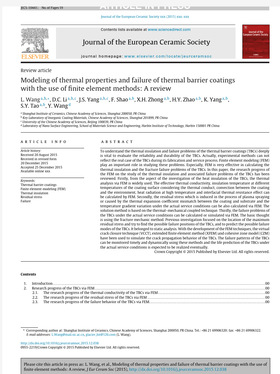
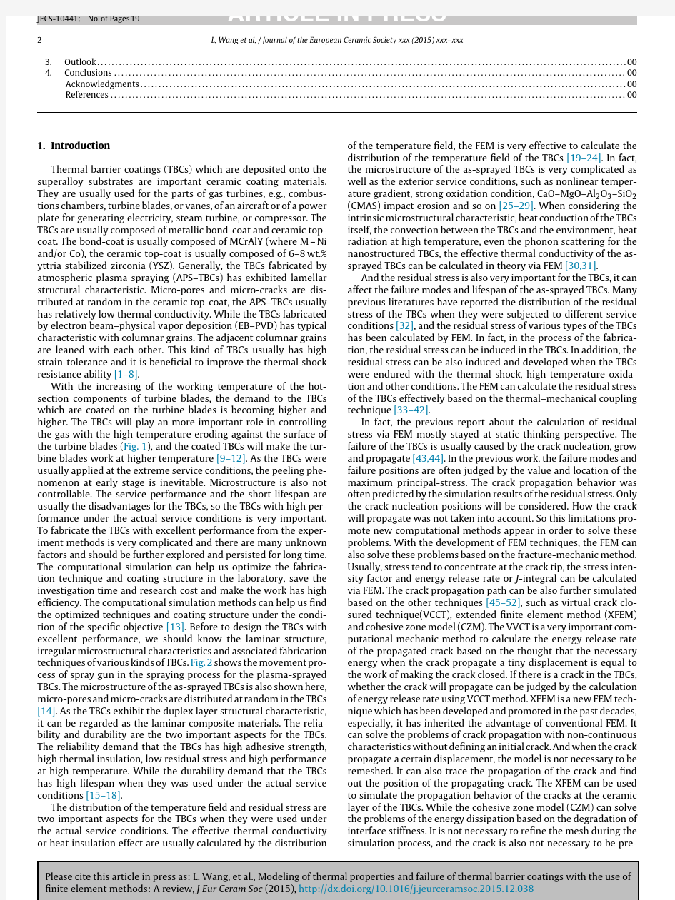
With the increasing of the working temperature of the hot-section components of turbine blades,the demand to the TBCs which are coated on the turbine blades is becoming higher and higher.The TBCs will play an more important role in controlling the gas with the high temperature eroding against the surface of the turbine blades(Fig.1),and the coated TBCs will make the tur-bine blades work at higher temperature[9–12].As the TBCs were usually applied at the extreme service conditions,the peeling phe-nomenon at early stage is inevitable.Microstructure is also not controllable.The service performance and the short lifespan are usually the disadvantages for the TBCs,so the TBCs with high per-formance under the actual service conditions is very important. To fabricate the TBCs with excellent performance from the exper-iment methods is very complicated and there are many unknown factors and should be further explored and persisted for long time. The computational simulation can help us optimize the fabrica-tion technique and coating structure in the laboratory,save the investigation time and research cost and make the work has high ef?ciency.The computational simulation methods can help us?nd the optimized techniques and coating structure under the condi-tion of the speci?c objective[13].Before to design the TBCs with excellent performance,we should know the laminar structure, irregular microstructural characteristics and associated fabrication techniques of various kinds of TBCs.Fig.2shows the movement pro-cess of spray gun in the spraying process for the plasma-sprayed TBCs.The microstructure of the as-sprayed TBCs is also shown here, micro-pores and micro-cracks are distributed at random in the TBCs [14].As the TBCs exhibit the duplex layer structural characteristic, it can be regarded as the laminar composite materials.The relia-bility and durability are the two important aspects for the TBCs. The reliability demand that the TBCs has high adhesive strength, high thermal insulation,low residual stress and high performance at high temperature.While the durability demand that the TBCs has high lifespan when they was used under the actual service conditions[15–18].
The distribution of the temperature?eld and residual stress are two important aspects for the TBCs when they were used under the actual service conditions.The effective thermal conductivity or heat insulation effect are usually calculated by the distribution of the temperature?eld,the FEM is very effective to calculate the distribution of the temperature?eld of the TBCs[19–24].In fact, the microstructure of the as-sprayed TBCs is very complicated as well as the exterior service conditions,such as nonlinear temper-ature gradient,strong oxidation condition,CaO–MgO–Al2O3–SiO2 (CMAS)impact erosion and so on[25–29].When considering the intrinsic microstructural characteristic,heat conduction of the TBCs itself,the convection between the TBCs and the environment,heat radiation at high temperature,even the phonon scattering for the nanostructured TBCs,the effective thermal conductivity of the as-sprayed TBCs can be calculated in theory via FEM[30,31].
And the residual stress is also very important for the TBCs,it can affect the failure modes and lifespan of the as-sprayed TBCs.Many previous literatures have reported the distribution of the residual stress of the TBCs when they were subjected to different service conditions[32],and the residual stress of various types of the TBCs has been calculated by FEM.In fact,in the process of the fabrica-tion,the residual stress can be induced in the TBCs.In addition,the residual stress can be also induced and developed when the TBCs were endured with the thermal shock,high temperature oxida-tion and other conditions.The FEM can calculate the residual stress of the TBCs effectively based on the thermal–mechanical coupling technique[33–42].
In fact,the previous report about the calculation of residual stress via FEM mostly stayed at static thinking perspective.The failure of the TBCs is usually caused by the crack nucleation,grow and propagate[43,44].In the previous work,the failure modes and failure positions are often judged by the value and location of the maximum principal-stress.The crack propagation behavior was often predicted by the simulation results of the residual stress.Only the crack nucleation positions will be considered.How the crack will propagate was not taken into account.So this limitations pro-mote new computational methods appear in order to solve these problems.With the development of FEM techniques,the FEM can also solve these problems based on the fracture-mechanic method. Usually,stress tend to concentrate at the crack tip,the stress inten-sity factor and energy release rate or J-integral can be calculated via FEM.The crack propagation path can be also further simulated based on the other techniques[45–52],such as virtual crack clo-sured technique(VCCT),extended?nite element method(XFEM) and cohesive zone model(CZM).The VVCT is a very important com-putational mechanic method to calculate the energy release rate of the propagated crack based on the thought that the necessary energy when the crack propagate a tiny displacement is equal to the work of making the crack closed.If there is a crack in the TBCs, whether the crack will propagate can be judged by the calculation of energy release rate using VCCT method.XFEM is a new FEM tech-nique which has been developed and promoted in the past decades, especially,it has inherited the advantage of conventional FEM.It can solve the problems of crack propagation with non-continuous characteristics without de?ning an initial crack.And when the crack propagate a certain displacement,the model is not necessary to be remeshed.It can also trace the propagation of the crack and?nd out the position of the propagating crack.The XFEM can be used to simulate the propagation behavior of the cracks at the ceramic layer of the TBCs.While the cohesive zone model(CZM)can solve the problems of the energy dissipation based on the degradation of interface stiffness.It is not necessary to re?ne the mesh during the simulation process,and the crack is also not necessary to be pre-
L.Wang et al./Journal of the European Ceramic Society xxx (2015)xxx–xxx
3
Fig.1.The history of the development for the superalloy and the thermal barrier coatings (a)actual inner image of the turbine (b)TBC coated on the turbine blade (c)[9–12].
fabricated.The CZM is very effective to solve the problems of the interfacial cracking,especially the failure at the bond-coat/top-coat interface of the TBCs.
The objective of the current work is to review the recent progress of the ?nite element modeling (FEM)on the study of the thermal insulation and the associated failure problems of the TBCs.These aspects of application for the FEM in the investigation of the TBCs has been introduced in detail.With the devolvement of FEM tech-niques,more complicated problems will be solved eventually based on the modi?ed FEM techniques.
2.Research progress of the TBCs via FEM
2.1.The research progress of the thermal conductivity of the TBCs via FEM
Thermal conductivity of the TBCs is a very important parameter to evaluate the reliability of the https://www.doczj.com/doc/b616234975.html,ually,as for the TBCs,when only the thermal conductivity has been considered,the lower,the better.In other words,the low thermal conductivity can guaran-tee that the TBCs has high thermal insulation effect.So it can be seen that the low thermal conductivity and high thermal insula-tion effect are equivalent.In fact,
there are many factors that will affect the effective thermal conductivity of the TBCs.The mate-rial itself is very important for the actual application of the TBCs.The low intrinsic thermal conductivity is the most important stan-Fig.2.Raster pattern in the x –y plane for one cycle of gun movement and the microstructure of the as-sprayed coating [14].
dard to select the suitable materials as the candidate of the TBCs.In addition,the coating thickness is an important factor to improve the thermal insulation effect of the as-sprayed TBCs.The previous investigation has indicated that the thermal insulation effect will increase with the top-coat thickness increasing due to the lower thermal conductivity of the ceramic top-coat compared with the other layers of the TBCs,but the accumulated residual stress in the ceramic top-coat will also increase with the thickness of the top-coat increasing due to the overlay of the passage of the splats.The failure of the as-sprayed coating can occur easily.Especially,when the thickness of the coating reach to or beyond a certain value,the bulking and peeling off phenomenon can be observed directly after thermal spraying [53].
The primary simulation work focused on the calculation of the heat transfer of the TBCs while the in?uence of the defects (micro-pores and micro-cracks)are also taken into account.The calculation of the effective thermal conductivity of the as-sprayed TBCs is based on the classic Fournier heat transfer law.The heat conduction equa-tion in three dimension direction can be expressed as [54]:
??x (k x ?T ?x )+??y (k y ?T ?y )+??z (k z ?T ?z )+q v =??t
( cT )(1)
where T ,t and indicate the transient temperature,time and the density,respectively.k x ,k y ,k z represent the thermal conductivities in x ,y and z direction,respectively.C and q v is the heat capacity and the intensity of the internal heat source in the corresponding space,respectively.
The as-sprayed TBCs can be viewed as a isolated heat source,so q v in Eq.(1)is equal to zero.The heat usually transfer from the coat-ing surface of the TBCs to the backside of the superalloy substrates,i.e.,the through thickness direction (spray direction)has only been considered.So Eq.(1)can be further simpli?ed as follows [55,56]:
?T ?t
=
k C p ?2
T
?y 2(2)
In fact,the pro?le of the coating along the left and right bound-aries of the TBCs model are considered to be adiabatic,i.e.,d T/d n =0,
the effective thermal conductivity in the through-thickness direc-tion (spray direction)of the TBCs can be calculated from [57]:
k eff
=
h TW
bot
k (n ?T )d
(3)
where h indicates the average thickness of the coating model with-out considering the micro-rough effect of the surface of the TBCs,W
4L.Wang et al./Journal of the European Ceramic Society xxx(2015)xxx–xxx
is the width of the coating model,respectively, T is the tempera-ture difference between the surface of the TBCs and the backside of the coating model,and bot represents the lower horizontal bound-ary of the coating model with normal vector n.It can be further seen that the effective thermal conductivity(k eff)of the TBCs is inversely proportional to the temperature difference T(insulation temper-ature)according to Eq.(3).The detailed calculation procedure of the effective thermal conductivity via FEM can be seen in our previous published paper[58].
The in?uence of the defects(micro-pores and micro-cracks)on the k eff or the thermal insulation effect can be calculated via?nite element modeling(FEM).The spatial and geometrical character-istics of pores will play an important role in affecting the k eff or thermal insulation effect of TBCs.The k eff of the TBCs will reduce with the increasing of the size of the micro-pores which were dis-tributed at the inner of the top-coat.It is bene?cial to increase the size of micro-pores of TBCs without sacri?cing the strength of the TBCs.The k eff of TBCs will increase if the pores existed on the sur-face of the TBCs,and the k eff will also increase with the depth of micro-pores increasing from the surface to the inner of the coat-ing.It is imagined that laser remelting of the surface of the TBCs is an effective method to eliminate the micro-pores on the surface, and thus resulting in the decline of the k eff of TBCs.But the laser treatment will induce large residual stress in the TBCs and eventu-ally affect the service lifetime of the TBCs.When the fraction of the micro-pores has a constant value,the geometric shapes also play an important role in affecting the k eff of the TBCs.When the direction of thermal?ux is?xed,the k eff will be different at different direc-tions.Especially,as for the elliptic type pores which exist at the inner of the top-coat of the TBCs,when the major axis of the ellip-tic pore is parallel to the interface direction(vertical to the spray direction),the k eff is the lowest.The k eff of TBCs will reduce with the increase of the number of passages(i.e.,number of layers)or the decrease of the space between the adjacent micro-pores.CMM (computational-micro mechanic)is an effective method to evaluate the k eff of actual TBCs.Sometimes it may play an important role in predicting the k eff or insulation temperature of actual TBCs based on the actual SEM image of the TBCs.The fraction of the defects (micro-pores and micro-cracks)that will affect the overall k eff of TBCs compared with the orientation angle and shape coef?cient of the defects is the most important factor[59–61].
The radiative properties[62]and interfacial thermal resistance [63]are also very important factors to affect the k eff of the TBCs.The radiative properties on the k eff of the TBCs have been investigated and extensively developed by Yang et al.[64].They have devel-oped a Finite–Difference–Time–Domain(FDTD)method which was employed to simulate the radiative heat transfer behaviors of TBCs with different types of microstructures[65].
In addition,the object-oriented?nite(OOF)element method has been used to calculate the actual k eff of the as-sprayed TBCs.The OOF was based on the actual image of the TBCs,this program can be used to depict the actual SEM image of the coating and can trans-form it to the?nite element mesh with assigned properties and the mesh can be imported to the ABAQUS or ANSYS software.The advantage or merit of this method is that it can solve the k eff based on the actual2D image of the as-sprayed coatings.Especially,the OOF method can solve the actual thermal?ux around the defects (micro-pores and micro-cracks)effectively[66–68].
The basic thought of the OOF program is to transform the prim-itive image to the?nite element mesh based on the colors or grayscale levels of the primitive SEM image,every?nite element mesh indicate a pixels groups with a?xed gray level with a spe-ci?c constituent.In this program,setting threshold pixel value is very important,the generated?nite element mesh can be further assigned with materials properties,initial and boundary conditions, and eventually can be solved in the ANSYS or ABAQUS software.As for the TBCs,the matrix phase and micro-pores phase including the crack phase can be distinguished in this program.Especially,the grid at the interfaces between different phases can be also re?ned. At last,the overall k eff can be calculated.Fig.3shows the model construction in the SEM/OOF approach,the distribution of the tem-perature?eld and the heat?ux around the micro-defects can be also obtained via this modeling methods[69].
In addition,some analytical models have also been used to calcu-late the effective thermal conductivity of the TBCs[70–72].Zigzag morphology pores which existed in the highly porous zirconia based TBCs can impede heat?ow through the thickness direction of the coating based on the analysis result using a combined ana-lytical/numerical study(Fig.4).The effects of volume fraction,type, orientation and spacing of the pores,together with the wave length and the amplitude of zig-zag pore microstructures on overall ther-mal performance are quanti?ed.The results further indicate that even a few volume percent of zig-zag inter-column pores oriented normal to the substrate surface can reduce the overall k eff of the coatings signi?cantly[73].
2.2.The research progress of the residual stress of the TBCs via
FEM
The calculation of the residual stress via FEM has occupied a large portion on the aspect of the investigation of the TBCs.Espe-cially,the residual stress after plasma spraying is very important to evaluate the reliability of the TBCs and further optimize the fabrica-tion techniques of the TBCs,and the residual stress of the TBCs with many different structures and compositions have been calculated via https://www.doczj.com/doc/b616234975.html,ually,the residual stress in the TBCs after thermal spray-ing often include the following four parts,quenching stress( q), thermal mismatch stress( t),impact stress( i)and phase transfor-mation stress( p),so the total residual stress( )can be written as follows:
= q+ t+ i+ p(4) The quenching stress q can be expressed as follows:
q=?c(T m?T s)E c(5) where?c,T m,T s and E c are the coef?cient of thermal expan-sion(CTE)of coating,melting point of the sprayed material, substrate temperature during spraying and elastic modulus of coat-ing,respectively.The quenching stress can be de?ned as the stress which is induced when the hotter splats impinged onto the pre-vious cooler deposits[74,75].In fact,as ceramic coating is brittle, the actual quenching stress may be lower than that of the calcu-lated value which is attributed to that the microcrack formation will relieve the stress concentration within the corresponding coating layers.
Another major component of residual stress in the as-sprayed TBCs is the thermal mismatch stress.The thermal mismatch stress of the TBCs was usually generated owing to the coef?cient of thermal expansion(CTE)mismatch between the ceramic layer(top-coat)and the substrate/metallic layer(bond-coat)during the whole coating system(including the superalloy substrate)cooled together from the high temperature spraying state to the ambient temper-ature.When the two-dimensional stress-strain model of TBCs was considered,the thermal stress at the surface of coating t can be expressed as follows:
t=E c ? T
1+
1? 2
(6) where ?, T,and are CTE mismatch between the substrate and coating,the temperature difference upon cooling and the Poisson’s ratio of coating,respectively.In fact,this analytical solution does not consider the effect of coating thickness,it must be specially
L.Wang et al./Journal of the European Ceramic Society xxx(2015)xxx–xxx5
Fig.3.Model construction process in the SEM/OOF approach.(a)SEM image(170×170?m2)of F&C(fused and crushed)coating specimen with darker area representing pores.(b)Outline of pores generated from the micrograph with7.4%local porosity.(c)Finite element mesh.Transient temperature and heat?ux of SEM/OOF model for the sintered coating.The model dimensions are170×170?m2.(d,e and f)indicate the temperature pro?le,red color indicates high temperature.(g,h and i)indicate heat?ux pro?le,red color indicates high heat?ux[69].(For interpretation of the references to color in this?gure legend,the reader is referred to the web version of this article.)
pointed out here that Eq.(6)may be not applicable when consider-ing the thick coatings.In fact,when the thickness of the as-sprayed coating exceed a certain value,the coatings may peel off from the substrate directly,but the thick thermal barrier coatings(TTBCs) will be exclusively due to the existence of segmented cracks which will relieve the stress concentration at the inner of the coating.The impacting stress can be viewed as the induced stress when the high temperature molten splats impacts onto the underlying harder and cool substrates.In the process of spraying,the substrates will be pre-heated before spraying.And the molten splats impacts onto the underling splats with relative high temperature,the molten splats will shrink,and the deformation of elastic formation will occur. Once the molten splats spread along the previous deposited splats, the induced stress will nearly release completely.So the impact stress can be negligible.The phase transformation-induced stress was usually generated from the solidi?cation of liquid particles or solid state transformation in the process of plasma https://www.doczj.com/doc/b616234975.html,u-ally,the phase transformation-induced stress can be added via the subroutine in the process of?nite element simulation.But in fact,as for the8wt.%Y2O3stabilized zirconia(8YSZ)TBCs,as the addition of Y2O3will inhibit the occurrence of the phase transformation of ZrO2at a certain degree.The phase transformation-induced stress will be not considered.The overall magnitude of residual stress in TBCs is the summation of quenching stress q and thermal stress t when the contribution of impact stress and the stress due to the phase transformation is negligible[76].The residual stress can be written eventually as follows:
= q+ t(7) There are many literatures about the simulation of the residual stress in the previous work,these work focused on the distribution and maximum stress analysis in the TBCs after thermal spray-ing or under the actual service conditions.Wang et al.[77]have simulated the residual stress of the TBCs using birth and death element technique,they have considered the build-up process of the thermal-sprayed coating,The residual stress as the function of thermal spray history has been established due to that the coating was formed layer by layer.Wang et al.[78,79]also have simu-lated the micro-compression behavior of the TBCs fabricated by atmospheric plasma spraying and electron beam-physical vapor deposition,they found that the stress existed in the coatings will change the microstructure of the as-sprayed coatings.The cracks may be induced under the action of the stress.The continuous imposed stress will promote the crack propagate along a certain direction.Some stress at a speci?c direction will promote the inter-face movement,pores deformation and pores healing.Especially,
6L.Wang et al./Journal of the European Ceramic Society xxx(2015)xxx–xxx
Fig.4.Typical zig-zag pore structure of a EB–DVD coating.Zig-zag pores are at different scale levels[73].
as for the TBCs with the characteristics of columnar grains,the kink bands and shear bands can be formed due to the action of the stress. The residual stress and the corresponding failure mechanism of the TBCs caused by impression has also been discussed systematically.
In addition,the residual stress in the TBCs during thermal shock, high temperature oxidation and other service conditions have all been simulated and analyzed.As for the thermal shock process,the large temperature gradient occur in this process,and large residual stress will occur at the interfaces of the TBCs due to the mismatch of thermal expansion coef?cients between the ceramic layer and metallic layer.With the thermal cycling number increasing,a con-tinuous TGO layer will be formed and grown gradually,the stress in the TGO even reach to several GPa,and the TGO morphology will be very irregular,and the stress will have a special distribution around the TGO layer.The irregular microstructure of the top-coat of the TBCs,the irregular TC/TGO,TGO/BC interface,the compli-cated chemical compositions of the TGO will make the stress state at the TBCs very complicated.In addition,these geometrical fac-tors and the materials properties are also dependent on the service temperature,all the factors will change with the variation of exte-rior environment,so it is very hard to calculate the residual stress in the TBCs accurately.Gupta et al.[80]have used OOF method to establish the irregular bond-coat/top-coat interface and simulate the residual stress distribution at different positions of this irregular interface(Fig.5).Their investigation results further indicated that the distribution characteristics of the residual stress are strongly dependent on the curvature of the interface.
As for the high temperature oxidation,TGO is the most impor-tant factor for the failure of the TBCs.The creep effect at above 600?C is also very important for the re-distribution of the residual stress in the TBCs,the creep effect of the substrate,metallic layer, TGO layer and top-coat layer will relieve some stress concentra-tion,and the element diffusion near the metallic layer/ceramic layer interface will also has a very important effect on the re-distribution of the residual stress.
Su et al.[81]have investigated the effect of TGO creep on top-coat cracking induced by cyclic displacement instability in TBCs. Their investigation results further indicated the creep of the TGO layer will reduce the normal stress level along the top-coat/bond-coat interface direction(Fig.6).The normal stress level will decline with increasing the creep value of the TGO layer.
As for the CMAS impact erosion,the exterior particle will impact onto the surface of the TBCs.And then at high temperature,the melted salt will penetrate into the inner of the TBCs.Some com-pounds will take reaction and the erosion depth will gradually increase with the erosion time increasing.The resulting stress and
L.Wang et al./Journal of the European Ceramic Society xxx(2015)xxx–xxx7 Fig.5.SEM microstructure image of a TBC cross-section(leftmost)is used to create the?nite element model shown in the center.The substrate has been cropped.A part of the model illustrating the generated?nite element mesh is shown to the right with varying element sizes in the TGO and adjacent boundaries(a).(b and c)show the contour plots of the vertical residual stresses in the topcoat for HVOF samples(a)in the as-sprayed condition and(b)after200h of isothermal heat treatment[80].
the eventual failure of the TBCs came from the thermal-mechanical-chemistry coupled effect.
2.3.The research progress of the failure behavior of the TBCs via FEM
The failure behavior of the TBCs when they were subjected to actual service conditions is a dynamic progress.It was often associated with the residual stress,creep effect,sintering effects, oxidation and so on.But in all,the failure is often attributed to the crack nucleation,growth and propagation eventually.
The factors which can affect the failure modes and lifespan of the TBCs when they were endured with high temperature ther-mal cycling(Fig.7)are very complicated and unpredictable.They include the elastic–plastic deformation of the substrates and metal-lic layer(bond-coat),elastic deformation of the TGO layer and ceramic top-coat,thermally grown of the TGO layer,thermody-namic and kinetic process of the elements which are distributed at the two sides of the TGO layer,creep effect of each layer and the interfaces between two adjacent layers,exterior loading,variation rate of the temperature gradient,convection between the coating and environment and so on[82].
So many methods have been developed to simulate this mechanical behavior.In fact,the cracks in the as-sprayed TBCs are distributed at random.Generally,there are two distinct types of cracks,horizontal cracks and vertical cracks.The crack which has a certain orientation with the interface direction or spray direc-tion usually was not considered in the?nite element simulation. The segmentation cracks which are usually called vertical cracks are bene?cial to improve the anti-strain tolerance ability,and thus increase the thermal shock resistance ability.The TBCs fabricated by APS with microstructual characteristic of the segmentation cracks are just like the TBCs fabricated by electron beam-physical vapor deposition(EB-PVD),but this type of TBCs usually has higher thermal conductivity compared with that of the TBCs fabricated by APS which is due to that the vertical crack direction is parallel to the heat?ux direction.The horizontal crack is usually dangerous for the TBCs.Although it may decrease the effective thermal con-ductivity,the horizontal crack can propagate along the interface direction and eventually reach to the edge of the coating samples.
In addition,the thermally grown oxide(TGO)which are formed between the metallic layer and ceramic layer during long-term high temperature oxidation is also the main factor which will affect the failure behavior of the TBCs fabricated by APS,there existed large compressive residual stress in the TGO,and this stress tend to increase with the increase of the TGO thickness or growth of the TGO.The cracks initiated in the TGO or around the TGO,so the fail-ure modes will be very complicated due to the co-exist of the cracks and the TGO.The cracks initiated in the TGO are often horizontal cracks,the crack near the TGO are also often the horizontal cracks, and the vertical crack can also initiate around the peak or valley of the TGO.As the TGO often exhibit the wavelet morphology,the residual stress often has different distribution characteristic around the peak or valley of the TGO.FEM is an ef?cient method to solve the failure problems of the TBCs associated with the TGO.Firstly, there are many geometry models about the TGO used in the pro-cess of FEM.When the TGO was considered,the typical YSZ TBCs were composed of four layers:super-alloy substrate,metallic layer, TGO layer and YSZ layer.The interface between the TGO/TC layer, TGO/BC layer were often considered sinusoidal curve with a certain amplitude and wavelength equivalently.The corresponding inter-faces were also considered as semi-circle or sinusoid or cosinusoid
8L.Wang et al./Journal of the European Ceramic Society xxx(2015)xxx–xxx
Fig.6.Schematic illustration of TBCs:the cracks in the top-coat(TC)are associated with the displacement instability of TGO.The distribution characteristic and history of normal stress 22(A TGO indicates the creep value of the TGO layer):(a)along the prospective crack path after24thermal cycles during dwell time,and(b)the evolution of the maximum tensile stress in(a)as the thermal cycles increase[81].
in order to investigate the stress distribution of the TGO,especially at the valley and crest.Secondly,maybe the initial and boundary conditions are very different.In some cases,the process of the thick-ness increasing of the TGO was not considered when the residual stress induced during thermal shock or high temperature oxida-tion was simulated,and in the other cases,this process should be considered.In fact,creep often occurred in the metallic or ceramic layers,so the creep process was also considered in some previous work.Especially,when the temperature is over than600?C,the creep effect must be considered,the existence of the creep will release the stress at the interfaces and each layer of the TBCs more or less.Especially,when the TBCs were endured with long-term high temperature oxidation,the creep effect will reduce the stress level signi?cantly which can be also regarded as a factor to prolong the lifetime of the TBCs.
Vermaak et al.[83]have investigated the development of resid-ual stresses in the Zr-based oxide under the combined in?uence of molar volume expansion during the oxide formation,geometrical morphology of the metal/oxide interface and the creep of metal-lic substrate via FEM.The generation of tensile stresses capable of initiating the cracks was also discussed.As the oxide thickens,a cracking structure can be formed which is similar with the TGO layer in the TBCs.
Wang et al.[84]have simulated the residual stress development in the TBCs during thermal shock.They found that the maximum residual stress occurred at the initial stage of the cooling process in a thermal cycle.And the stress tend to concentrate at the tip of the surface crack compared with the inner crack in the ceramic layer,and the stress intensity factor is also the biggest compared with that of the cracks at the inner of the ceramic layer.In addition,
L.Wang et al./Journal of the European Ceramic Society xxx (2015)xxx–xxx
9
Fig.7.Examples of typical behavior and damage in an EB–PVD TBCs during in-phase thermomechanical fatigue (IP–TMF)testing mode:(a)creep curve of normalized average strain ε/ε0,where ε0is strain at ?rst loading.(b)Ratcheting behavior of the TBC system shown by the Increasing strain at low temperature after each loading cycle.(SEM)images (c–f)show (c)TBC layer cracking (image of a polished section,parallel to the actual loading axis),(d)macroscopic appearance of multiple fragmentation of TBC layer,(e)void formation in the BC layer,and (f)fatigue
crack growth and new TGO formation in the BC layer.(g)Delamination of TBC layer,(h)illustration of anisotropic TGO morphology (arrow,loading direction),and (i)an example of stress distribution in the TGO layer [82].
Fig.8.The radial stress at the tip of the cracks which are located at different positions (a)a pore and a crack at the surface (b)two cracks at the surface (c)a pore and a crack at the inner of the ceramic layer (d)two cracks at the inner of the ceramic layer [84].
when the distance between the crack and the neighbored pores are small enough,the pores will relieve the stress concentration more or less,this will further delay the crack initiation and reduce the propagation rate of the corresponding cracks,but the distance between the crack and the neighbored pore is far enough,it is not evident for the in?uence of pores on the neighbored cracks (Fig.8).
Since the long decades ago,the failure problem of the TBCs at high temperature is the core problem which troubled the researchers at home and aboard.This is due to that there are many factors which will affect the failure modes of the TBCs.But in all,It can be attributed to the inner reasons and exterior reasons,the inner reasons primarily re?ect the microstructure of the as-
10L.Wang et al./Journal of the European Ceramic Society xxx(2015)xxx–xxx
sprayed coatings including the microstructure,laminar structure, pores and micro-cracks.The exterior reasons include the actual ser-vice environments of the TBCs including the thermal shock,high temperature oxidation and foreign object damage(FOD)etc.What-ever the failure modes,it attributes to the interaction and co-action of the laminar interface and the cracks eventually.Amounts of work about the failure which is controlled by interface has been done by the researchers at home and aboard.
Firstly,from the aspect of evolution of the microstructure of the ceramic layer during thermal shock,the microstructure of the as-sprayed state and the stress evolution during thermal shock play a vital and key role in affecting the failure modes of the TBCs.The failure of the TBCs at high temperature is a accumulated dynamic process accompanied with the crack nucleation,growth and propa-gation,so the microstructure of the coatings will have an important effect on the propagation paths of the TBCs.While the laminar inter-face will play a more important role in capturing the crack which reach to the interface or the crack propagation path will kink around the interface due to the barrier effect of the interface.And the inter-face is often the weak positions of the coatings,the microstructure of the interface including the chemical compositions and geomet-ric morphology will change dynamically with the prolong of the high temperature service time,so the propagation patterns and the failure mechanism will be more complicated.The failure pro-cess of the TBCs during high temperature service is a complicated dynamic process which is associated with the change of temper-ature?eld,material properties and the evolution of the laminar interface[85,86].As for the TBCs which are endured with high tem-perature service,the possible laminar interface is shown in Fig.9. The existence of the laminar interfaces will play an important role in controlling the crack propagation near the laminar interface and affect the failure mechanism and lifespan of the TBCs eventually [87].
Interface properties play an important role in controlling the mechanical properties of the materials[88].As for the laminar interface of the TBCs,the complicate characteristic can be described with different mathematical function,so it can re?ect the in?uence of the laminar interface including the TGO layer on the distribution of the residual stress of the TBCs suf?ciently,and it can guarantee the calculation of the fracture mechanic parameters of the crack around the interface[89].Aleksanoglu et al.[90]have investigated the in?uence of exterior loading patterns on the failure modes of the plasma-sprayed TBCs,they found that the exterior load with different patterns will produce different deformation characteris-tics onto the laminar interface,and the eventual failure positions are also located at different laminar interfaces.The critical strain which induce the coating to failure has been determined via the simulation and acoustic emission methods.
Liu et al.[91]have investigated the in?uence of the curvature of the substrate on the residual stress around the laminar interface of the plasma-sprayed TBCs.They found that the change of the curva-ture of the substrate will further affect the curvature of the laminar interface of the coatings,and it will also affect the residual stress of the TC/TGO and the TGO/BC interface.And the propagation charac-teristic of the cracks around the TGO/TC and TGO/BC interface has been discussed systematically.And the mechanism of the interface movement that control the failure of the TBC has been proposed. Ranjbar-Far et al.[92]have used the ABAQUS software to reveal several typical failure mechanisms for the plasma-sprayed TBCs via the“debond”technique.The TGO/TC interface,TGO/BC inter-face and the laminar interfaces in the TC layer have been mainly discussed.They thought that these laminar interfaces are the weak positions of the TBCs.The stress concentration,crack propagation and the failure of the TBCs tend to happen at these laminar inter-faces,the roughness and the thickness of the TGO will affect the failure of the TBC directly,and the critical stress and the strain which induce the coating to failure were also determined by the two factors.B?ker et al.[93,94]have investigated the initiation and propagation of the cracks around the interface using?nite element methods.the investigation results indicate that the crack tend to propagate along the TGO/TC interface.As for the coatings with dif-ferent creep strength,the crack may initiate at the peak or valley of the laminar interface,the crack initiate at the valley may have larger energy release rate compared with that of the cracks initiate at the peak of the laminar interface.The crack which was located at the peak of the laminar interface can not release the residual stress effectively compared with that of the crack which was located at the valley of the laminar interface.Whether is captured when the crack propagate to the interface was strongly dependent on the creep properties of the coatings(Fig.10).
The investigation results further found that the radial stress is compressive stress at the peak of the coarse interface,the crack also tend to propagate parallel to the interface.When there existed fric-tion at the crack plane,the crack tend to kink at the interface.The creep effect will decline the propagation rate of the crack around the interface with a certain degree[95].In addition,the diffusion of elements at the TGO layer and the bond-coat will induce the grow and degradation of the TGO layer,and will further affect the dis-tribution of the residual stress and the propagation patterns of the cracks near the interfaces[96].Weber et al.[97]have found that the cracking of the coating interface has intense relationship with the thickness of the ceramic layer of the TBCs,the width and the inter-displacement of the cracks can be changed when improve the thickness of the ceramic layer properly,And changing the mode of the crack,reducing the stress concentration at the interface,delay-ing interface cracking,the existence of the segmentation cracks with a certain density at the ceramic layer will increase the tear work or fracture energy of the interface[98].
During the high temperature service,the increasing of the ther-mal cycling number will also increase the inelastic strain of the coating,change the morphology of the wrinkling or buckling,and affect the stress distribution which will further indicate that the fracture mechanic parameters of single crack has some limita-tion when understanding the facture behavior the interfaces[99], Bargraser et al.[100]have used modi?ed Paris law based on the amounts and propagation characteristic of the cracks around the interface,and the mathematical physical model has been proposed to predict the lifespan of the coating,the error of the predicted is in the range of10%compared with the experimental results.Sun et al.[101]have considered the?uctuate of the TGO layer and the growth of the TGO layer induced by the element of Al and O dif-fusion along the top-coat/bond-coat interface simultaneously.The FEM has been used to simulate the grown stress of the TGO layer, and the possible positions of the crack nucleation in the APS–TBCs and EB–PVD TBCs have been proposed and indicated(Fig.11).
Based on the above work,the previous investigation about the failure behavior of TBCs often focused on the analysis of stress, including the residual stress after plasma spraying,oxidation-induced stress,creep stress,accumulated stress during high temperature service(thermal shock,thermal cycling etc.).The fail-ure modes and failure tendency of TBCs are often judged by the stress level or the magnitude of the maximum stress,such as nor-mal stress,shear stress,longitude stress and?rst-principle stress etc.The investigation methods are mostly static.In fact,Frac-ture/crack growth is a phenomenon in which two surfaces are separated from each other,or material is progressively damaged under external loading.With the development of?nite element modeling techniques,many methods which can be used to simulate the crack propagation behavior timely and dynamically appeared. The virtual crack closured technique(VCCT),extended?nite ele-ment method(XFEM)and cohesive zone model(CZM)are three important methods which have been developed recently in the past
L.Wang et al./Journal of the European Ceramic Society xxx(2015)xxx–xxx11 Fig.9.Several laminar interface at the inner of the thermal barrier coatings[87].
Fig.10.The radial stress distribution around the valley of the TGO/TC interface before(a)and after the crack propagation(b)[93,94].
decades.Especially,as for the failure of TBCs,these three methods will play an important role in investigating the dynamic failure behavior.The detailed comparation of the three computational mechanical methods is displayed in Table1[102–118].
The virtual crack closure technique(VCCT)was initially devel-oped to calculate the energy-release rate(or J integral)of a cracked body.It has since been widely used in the modeling of the growth of interfacial crack which is located at the laminate composites.Gen-erally,a VCCT-based crack growth modeling procedures involves the following assumptions:(1)Crack propagation usually occurs along a prede?ned crack path;(2)the crack path is de?ned via interface elements of the corresponding FEM software.(3)The modeling material is linear elastic and can be isotropic,orthotropic or anisotropic.i.e.,the plastic properties is not considered in the simulation procedure(4)the analysis is quasi-static and does not account for transient effects.The simulated crack can be located in a material(layer)or along the interface of the two different materials or two adjacent layers.The fracture criteria is based on energy-release rates(J-integral)calculated using VCCT.Especially, the multiple cracks can be also modeled using VCCT based on the different cracks and corresponding fracture criteria.The multiple cracks can propagate simultaneously and independently from each other.In some special cases,some cracks can also merge to a sin-gle crack when they propagate along the same interface.Based on these characteristics,the VCCT is very suitable for modeling the interface cracking behavior of the TBCs.
Xu et al.[119]have investigated the interfacial cracking behav-ior for the top-coat/bond-coat interface in the TBCs using VCCT, they has established the plot of the driven force of the interfacial cracking as the function of the thickness and elastic modulus of the top-coat and bond-coat.Based on their simulation results,it was concluded that interfacial delamination can easily be initiated for a thick,stiff top coat.And the thickness and elastic modulus of the TBCs with high interfacial fracture resistance ability can be optimized experimentally.As the stress tend to concentrate at the crack tip,?ne mesh is set near the crack tip and the contour inte-gral regions in order to calculate the J-integral accurately.The crack propagation direction is assumed to be along the top-coat/bond-coat interface(Fig.12(a)).Three contours has been set in order to get accurate value of J-integral.Fig.12(b)shows the plot of strain energy release rate(SEER)as the function of the interfacial delam-ination length with different thickness of the top-coat layer.It can be seen from this?gure that the SEER has exhibited the increas-ing tendency with the increase of the thickness of the top-coat layer,but with the length of the interfacial delamination increas-ing,SEER?rstly increase to a local maximum value(G max)then decline to a steady-state(almost independent of the delamination length)in the processes of initiation and propagation of interfacial delamination of the TBCs.The corresponding G ss is usually regarded as an important parameter to describe the driving force of sta-ble spreading of interfacial delamination of the TBCs.Ding et al. [120]have investigated the crack propagation in TGO layer and TGO growth near a surface groove in a metallic substrate upon multi-ple thermal-mechanical cycling via VCCT.In the procedure of their simulation,two columns of repeated nodes were placed along the top-coat/bond-coat interface of the potential crack,and these nodes were bonded together as one node at the same geometrical loca-tion.The critical crack opening displacement(CCOD)criterion has been adopted in the process of simulation.The simulation results showed a good agreement with the experimental observation,and the simulation procedure will provide a guideline for the prediction of the failure in TGO,future design and optimization for TBCs.
The extended?nite element method(XFEM)as a new compu-tational mechanic method has also been developed recently with the development of fracture mechanics and?nite element model-ing techniques.It has exhibited unique advantage among the?nite
12
L.Wang et al./Journal of the European Ceramic Society xxx (2015)xxx–xxx
Fig.11.Schematic illustration of a typical TBC system with undulating TGO.The predominant growth mechanisms are schematically depicted particularly for TGO convex and concave portions upward (a).The consequent growth strain in TGO is also shown (b)micro-crack
patterns (excluding BC failure)around an undulating TGO layer when growth stress acts as the driving force of fracture:(c)possible fracture zone in an APS TBCs;(d)possible fracture zone in an EB–PVD TBCs [101].
Fig.12.Characteristic of the contour integrals around an interface crack tip (a)The strain energy release rate as a function of interfacial delamination length for different TC thicknesses.The G max stands for the maximum value of strain energy release rate (b)[119].
element modeling methods.It has inherited the advantages of con-ventional ?nite element methods (CFEM),and it is very effective in modeling the crack propagation of the continuum body.The funda-mental differences between XFEM and CFEM is that the used mesh in XFEM is not dependent on the geometry or physical interface at the inner of structural body.And this will overcome the dif?culties
L.Wang
et al./Journal of the European Ceramic Society xxx (2015)xxx–xxx
13
Table 1
Comparation of VCCT,XFEM and CZM.
Methods of computational mechanic Description of the model
Advantages
Disadvantages
References Notes
Virtual Crack Closed Technique (VCCT)
?Be very suitable to calculate the energy release rate during the crack propagation based on the thought that the necessary
energy when the crack propagate a tiny
displacement is equal to
the work of making the crack closed
?An initial crack should be prede?ned before the simulation of crack propagation
[102–104]
Calculate J integration
?The propagation path of the crack
should be also de?ned before the simulation process
Extended ?nite element
method(XFEM)
?Be not necessary to de?ne an initial crack
?When the crack propagate to a
complicated interface,it is not very effective to modeling the problems of the interfacial fracture
[105–112]
Calculate propagation of the crack at the inner of the top coat
?Can solve the problems of crack propagation with non-continuous characteristics
?The propagation path of the cracks is also not necessary to be
de?ned,not dependent on the inner
details of geometrical structure only dependent on the exterior shape of the structural body ?When the crack propagate a certain displacement,the
model is not necessary to be remeshed ?Can trace the
propagation path of the crack
Cohesive zone model (CZM)
?It can solve the
problem of the energy dissipation based on the degradation of interface stiffness
?Many parameters should be set
[113–118]
Interfacial fracture
?It is not necessary to re?ne the mesh during the simulation process,and the crack is not necessary to be prefabricated
?The computational cost is high
of meshing around the zones where has high stress concentration or lager deformation (crack tip,irregular interface,etc.)while these positions usually should have super-?ne mesh.The model is not necessary to be re-meshed when perform the calculation of crack propagation.The core thought of the XFEM is that it use the expan-sion of shape functions with the discontinuous characteristics to represent the discontinuity of the calculated region.In the process
of calculation,the description of non-continuous ?led is not entirely independent of mesh boundary.It has exhibited advantage in treat-ing the fracture problems.Any propagation path can be simulated using the XFEM,it can also simulate the crack propagation behavior of heterogeneous materials with pores and inclusions.
Yang et al.[121]have investigated the fracture process of notched 8YSZ samples via XFEM,the ERR of the standing coat-
14
L.Wang et al./Journal of the European Ceramic Society xxx (2015)xxx–xxx
Fig.13.Stress distribution for the TGO with different elastic modulus and surface crack locations:(a)peak,E TGO =400GPa,(b)middle,E TGO =400GPa,(c)valley,E TGO =400GPa,(d)peak,
E TGO =40GPa,(e)middle,E TGO =40GPa,(f)valley,E TGO =40GPa.In these cases,the crack length is selected to be 20mm.Other parameters are considered to be same [122].
Fig.14.Crack propagation paths in the TBCs for different crack positions and TGO with different elastic modulus:(a)peak,E TGO =400GPa,(b)middle,E TGO =400GPa,(c)valley,E TGO =400GPa,(d)peak,E TGO =40GPa,(e)middle,E TGO =40GPa,and (f)valley,E TGO =40GPa [122].
ing samples was estimated by the known fracture strength and Young’s modulus.The calculated ERR was transformed into the corresponding fracture toughness of the standing coatings which showed a good agreement with the experimental results by sin-gle edge notched bending (SENB)tests.The authors thought that the obtained material properties of XFEM would play a crucial role in predicting the reliability and durability of TBCs with irregular geometry in the future.In addition,Fan et al.[122]have investi-gated the effect of TGO on the multiple surface cracking behaviors in APS–TBCs.The extended ?nite element method (XFEM)and peri-odic boundary conditions have been used to investigate the TGO dependences of periodic surface crack driving force and crack prop-agation path.the stress distribution has been calculated (Fig.13),and the crack propagation path has also been simulated via XFEM (Fig.14).The investigation results indicate that the effect of elastic
modulus of TGO layer is signi?cant on controlling the strain energy release rate.The associated fracture mechanism is mainly governed by the elastic mismatch across the top-coat/bond-coat interfaces,which can be used as a guide for the design of good strain-tolerant APS–TBCs.Zhang et al.[123]have investigated the effect of inter-face roughness on the strain energy release rate (SERR)and surface cracking behavior in APS–TBCs via XFEM.The driving force of mul-tiple surface cracks in the coating/substrate system are predicated and presented.They found that the roughness of the interface has signi?cant effect on the SERR,the distribution of the interfacial stress and patterns of the crack propagation.The distributions of stress and strain energy release rate in the regions of convex and concave asperities of the substrate are completely different.The oscillatory characteristics of SERR is attributed to the variation of the interface asperity.And some positions of interface can cause
L.Wang et al./Journal of the European Ceramic Society xxx(2015)xxx–xxx15
the local arrest of the cracks which are located at the surface,the simulation results will provide a very important routine that the durability of as-sprayed TBCs with multiple cracks can be enhanced by controlling the morphology of the interface arti?cially.Wang et al.[124]have investigated the crack propagation behavior of the TBCs during thermal cycling,and explained the failure mechanism of the TBCs induced by the prorogation of horizontal crack or ver-tical crack.Especially very interesting,they also propose a spring vibrator model to further describe the crack propagation patterns in the TBCs based on the simulation results.
Fracture or delamination along an interface between two adja-cent phases plays a major role in determining the toughness and ductility of the multi-phase materials.Interface delamination can be modeled by traditional fracture mechanics methods,such as the nodal release technique.Alternatively,you can use techniques that introduce fracture mechanism by adopting softening relation-ships between tractions and the separations directly,which in turn introduce a critical fracture energy that is also the energy required to break apart the interface surfaces.This technique is called the cohesive zone model(CZM)[125,126].The interface surfaces of the materials can be represented by a special set of interface ele-ments or contact elements,and CZM can be used to characterize the constitutive behavior of the interface.This approach introduces failure mechanisms by using the hardening-softening relationships between the separations and incorporating the corresponding trac-tions across the interface.Similarly,this modeling technique is also well suited for simulating the fracture process in a homoge-neous medium.The CZM uses interface or contact elements to allow the separation of the surfaces and the cohesive material model to describe the separation behavior of the surfaces.This approach applies to both the simulation of fracture in a homogeneous mate-rial as well as interfacial delamination along the interface between two materials.
Leo et al.[127]have investigated the interfacial delamination behavior of the TBCs via CZM using a traction-separation type law. The standard tension experiment,a novel shear experiment and a novel asymmetric four-point bending mixed-mode experiment have been performed incorporated with FEM.The authors thought that the methodology is applied to determine the material param-eters and the interfacial properties for a APS–TBCs.Soulignac et al. [128]have investigated the interfacial mechanical properties of a typical EB–PVD TBC system via CZM.The mechanical compres-sive test at high temperature has been performed,and it has been found that a high level of compression will promote the interfa-cial crack propagate after the?rst spallation event,the parameters of the Needleman’s CZM were identi?ed.The in?uence of the mor-phology of the ceramic-layer/metallic-layer interface on the failure evolution was numerically investigated.And the simulation results agreed well with the known delamination process in TBCs.Fan et al. [129]have investigated the effect of periodic surface cracks on the interfacial fracture of TBCs.The CZM has been used in their work. It is found that the spacing of the surface cracks has signi?cant effect on the initiation and propagation of short interface crack. Their work further indicate that an surface crack with appropriately high density can enhance the durability of TBCs(Fig.15).Bia?as et al. [130]have modeled the development of interfacial micro-crack of APS–TBCs using CZM,the simulation results showed that the devel-opment of the interfacial crack allows for a micro-crack formation within APS TBCs.The subsequent TGO growth results in a tensional zone within the TGO layer.Linking of the micro-cracks at the inter-face and within TBCs through TGO layer could lead to a coating delamination eventually.Hille et al.[131]have investigated the fracture patterns and evolutions of the overall crack growth of the TBCs via CZM,a comparison between TBCs composed of different constitutive models has been made.The simulation results clearly illustrated the importance of accounting for the effects of plastic-ity in the bond-coat layer and anisotropy in the top-coat layer.The computed fracture pro?le was in good correspondence with the experimental observations.Zhu et al.[132]have investigated the interaction of surface cracking and interfacial delamination in TBCs under tension by using CZM.It was found that the surface crack density(D S)has a signi?cant effect on the initiation and propaga-tion of interfacial delamination.The interfacial delamination length will decrease with the increase of the D S.The saturated crack den-sities decrease with the increase of the thickness of the ceramic layer and interfacial delamination length.And the critical D S with-out interfacial delamination decreases as the interfacial adhesion energy increase.The results indicated that to improve the D S and interfacial adhesion energy will decline the probability of interfa-cial delamination.Zhu et al.[133]have calculated the interfacial adhesion energies of TBCs using CZM combined with compression test in order to understand the failure mechanisms and predict the lifetime of the TBCs.Fig.16(a)and(b)shows the used model and mesh in their work,respectively.Fig.16(c)shows the crack initia-tion and propagation process during delamination.The degradation of interface cohesive elements was decided by a stiffness degrada-tion variable(SDEG).When the value of SDEG reached to1,the corresponding cohesive elements failed and a crack occurred.With the increase of strain,interface damage initiates when the dam-age criterion was satis?ed and interface cracks occur.As strain reached?0.5%,delamination started.The interface crack quickly will increase with the compressive strain increasing.Fig.16(d) shows the crack length versus applied strain curve based on CZM. The simulation procedure was repeated until the best?t reached between simulations and experiments by changing the interfacial adhesion energy.The corresponding value was de?ned as the inter-facial adhesion energy of TBCs.It was found that the interfacial adhesion energy of TBCs was in the range of100–130J/m2,which ?tted the experimental data quite well.
The interface fracture mechanic based on single crack has also been investigated.Especially,the computational micro-mechanic (CMM)is a very effective method to help us gain insight on the failure process of the actual TBCs[134,135].The interfacial crack-ing characteristic including the interface chemical composition and superstructure have also been investigated[136,137].The failure behaviors of the coating when endured with three-point bend-ing,four point bending and uniaxial axial tension have also been investigated using simulation and acoustic emission techniques [138–143].The crack propagation of the cracks during thermal shock has also been investigated based on the actual image of the coating[144].Wang et al.[145]have investigated the3D spatial evolution processes of damage and failure under uniaxial tension using FEM combined with microcomputer tomography(micro-CT). The Micro-CT can be used to generate a3D microscopic structural model which can re?ect the actual interface morphology and pore distribution of TBCs.The simulation results agreed well with the experimental observation.And the simulation results show that the local stress concentration induces two types of crack sources which are located either at the top-coat/bond-coat interface or along the pore boundaries.As the load increase,only the micro-cracks at the top-coat/bond-coat interface amalgamate and begin to form a pri-mary crack.Then the primary crack propagates rapidly horizontally along the interface,resulting in an undulating fracture morphology eventually.In fact,the above three methods are not independent with each other,they can be used jointly.Fukumasu et al.[146] have developed a numerical model based on a spherical rigid inden-ter in contact with a coated compliant substrate using FEM.Both cohesive and adhesive failure models were included in the sim-ulation process,allowing the evaluation of failure in the coating and/or at the coating/substrate interface.The XFEM and CZM have been used simultaneously.The XFEM was applied to reproduce the cohesive cracks through the coating thickness,while the CZM
16L.Wang et al./Journal of the European Ceramic Society xxx(2015)xxx–xxx
Fig.15.Schematic illustration of two-dimensional plane strain problem for steady state periodic channeling cracks with interfacial cracks(a).Interfacial delamination behaviors for different cases of normalized surface crack spacings:(b)W/h f=10,(c)W/h f=20,and(d)W/h f=30[129].
was used to evaluate the interfacial crack which is located at the coating/substrate interface.This computational method can be also used for reference in the investigation of the failure of the TBCs. 3.Outlook
The failure of the TBCs is an inherent topic.The previous work is mostly focused on the simulation of the residual stress in the TBCs during thermal spray process and actual service process.The liter-atures about the lifetime prediction of the TBCs are rare,so there were much work to be done in the future about the lifetime predic-tion about the TBCs under different service conditions.In order to realize this goal,simulation of the crack propagation is an important method and route to solve the lifetime of the TBCs.Although the virtual crack closured technique(VCCT),extended?nite element method(XFEM)and cohesive zone model(CZM)have been used to solve the problems about the crack propagation,the simulation is restricted when there are many branched or linked cracks.How to judge the crack propagation?For example,when two cracks in the TBCs intersect,the two cracks will become one crack and propa-gate continuously along the different direction or they propagate separately along the different directions or the crack once inter-sect,the propagation behavior stopped?In addition,the interaction between the cracks and the laminar interface/layer interface is also a very important investigation topic.When multiple cracks propa-gate toward to the interface,once they reach to the interface,how the crack will propagate?The propagation of the crack will stop at the interface,or it will run through the interface and continue to propagate along a speci?c direction,or it will propagate along the interface?As for the TBCs,there are many micro-pores and micro-cracks which are distributed at random.In addition,many laminar interfaces and layer interfaces also existed in the TBCs. The problems that how the crack will propagate at this irregular microstructure is a very important research direction.There are no effective methods or programs to solve these problems till now. So there are still many challenging topics about the heat transfer and failure problems of the TBCs.Much work will be done in these aspects in the future.
4.Conclusions
In this paper,the research progress on the study of the thermal–mechanical coupling and associated failure problems of the thermal barrier coatings(TBCs)with the use of the?nite ele-ment method(FEM)has been reviewed.The following conclusions can be obtained as follows:
(1)The research progress of the heat transfer behavior which
has considered the heat conduction,heat convection and heat radiation at high temperature with the use of FEM has been overviewed.Especially,when more complicated TBCs model has been established,and the interface thermal resistance has been considered,the relevant simulation work has also been overviewed.The thermal insulation and the effective thermal
L.Wang et al./Journal of the European Ceramic Society xxx(2015)xxx–xxx17
Fig.16.Illustration of a?nite element model for the delamination of as-spayed TBCs(a);?nite element mesh and boundary conditions,where the yellow line represents the position of cohesive elements.The inset shows the detailed meshes around the interface between the top-coat and bond-coat(b);the contour plots of the variable SDEG for interfacial cohesive elements with the increase of compressive strain,the bottom?gure is the magni?ed contour plot at the crack tip(c);the plot of the variation of the interfacial crack length as the function of the compressive strain.The pink squares are experimental data,and the red,green and blue lines are?nite element results with interfacial adhesion energies equal to70,100and130J/m2,respectively.(d)[133].(For interpretation of the references to color in this?gure legend,the reader is referred to the web version of this article.)
conductivity can be further investigated based on the3D model with considering the real spatial morphology of the TBCs and more complicated exterior non-linear initial/boundary condi-tions via FEM.These work should be further done in the future.
(2)The research progress of the modeling about the residual stress
during thermal spraying and the actual service conditions(ther-mal cycling,high temperature oxidation,micro-compression etc.)has been overviewed.The calculation of the residual stress which has considered the geometric morphologies of various types of interfaces,high temperature creep effect and different exterior loading patterns has been reviewed and discussed sys-tematically.The calculation of the residual stress of TBCs with different microstructure and layer structure which has consid-ered more complicated initial and boundary conditions should be further investigated via FEM.Especially,some complicated non-linear factors can be added to the model.
(3)The virtual crack closured technique(VCCT),extended?nite
element method(XFEM)and cohesive zone model(CZM)are three important methods to simulate the crack propagation behavior of the TBCs.The research progress of the crack propagation behavior in the TBCs has been overviewed system-atically.The VCCT usually has been used to calculate the fracture mechanic parameters in order to further predict the tendency of the crack propagation.The XFEM has been used to simulate the propagation behavior of the crack at the inner of the top-coat of the TBCs.The CZM has been used to simulate the propagation behavior of the cracks at the interface.As the microstructure of the TBCs is very irregular,micro-pores,micro-cracks,laminar interface and layer interface co-existed at random,the problem that how the cracks will propagate at such complicated system is a challenging topic.And the interaction among the cracks and the interaction between the cracks and the irregular interface is still unknown.These three modeling techniques are still not mature and should be anticipated to be further developed.And
the lifetime prediction of the TBCs is expected to be realized in the future eventually.
Acknowledgments
This work was jointly supported by the National Natural Sci-ence Foundation of China(NSFC)under the Grant No.51202277, Young Scholar Project(No.12ZR1452000)supported by the Shang-hai Science and Technology Committee,and we also give our thanks to the special Project for Army-Civilian Combination of Shang-hai Municipal Commission of Economy and Informatization(No. JMJH2014053).The current work was also supported by the Major Program for Basic Research of Shanghai Science and Technology Committee(No.12DJ1400402),the Key Research Program of Chi-nese Academy of Sciences(No.KGZD-EW-T06)and the research grant(No.14DZ2261200)from Shanghai government. References
[1]P.P.Nitin,G.Maurice,H.J.Eric,Science296(5566)(2002)279–284.
[2]J.H.Perepezko,Science326(2009)1068–1069.
[3]A.G.Evans,D.R.Mumm,J.W.Hutehinson,G.H.Meier,F.S.Pettit,Prog.Mater.
Sci.46(5)(2001)505–553.
[4]S.Uwe,L.Christoph,F.Klaus,P.Manfred,S.B.Bilge,L.Odile,et al.,Aerosp.
Sci.Technol.7(1)(2003)73–80.
[5]M.Karadge,X.Zhao,M.Preuss,P.Xiao,Scripta Mater.54(4)(2006)639–644.
[6]A.C.Valdez,A.A.Morquecho,G.Vargas,Acta Mater.59(6)(2011)
2556–2562.
[7]W.Shen,F.C.Wang,Q.B.Fan,Appl.Math.Model.36(5)(2012)1995–2002.
[8]R.W.Trice,Y.J.Su,J.R.Mawdsley,K.T.Faber,J.Mater.Sci.37(11)(2002)
2359–2365.
[9]D.Shi?er,Future research directions to understanding factors in?uencing
advanced high temperature materials[C],in:2009Department of Defense
Corrosion Conference,Washington DC,2009.
[10]H.B.Zhao,C.G.Levi,H.N.G.Wadley,Surf.Coat.Technol.251(2014)74–86.
[11]D.R.Clarke,M.Oechsner,N.P.Padture,MRS Bulletin.37(10)(2012)891–941.
[12]T.S.Hille,T.J.Nijdam,A.S.J.Suiker,S.Turteltau,W.G.Sloof,Acta Mater.57
(2009)2624–2630.
[13]A.Shanian,https://www.doczj.com/doc/b616234975.html,ani,N.Vermaak,K.Bertoldi,T.Scarinci,M.Gerendas,J.
Appl.Mech.-T ASME79(2012)1–8.
18L.Wang et al./Journal of the European Ceramic Society xxx(2015)xxx–xxx
[14]S.A.Tsipas,I.O.Golosnoy,J.Eur.Ceram.Soc.31(2011)2923–2929.
[15]H.R.Lu,C.A.Wang,C.G.Zhang,S.Y.Tong,J.Eur.Ceram.Soc.35(2015)
1297–1306.
[16]E.P.Busso,L.Wright,H.E.Evans,L.N.McCartney,S.R.J.Saunders,S.Osgerby,
J.Nunn,Acta Mater.55(2007)1491–1503.
[17]D.Cojocaru,A.M.Karlsson,Int.J.Fatigue.28(2006)1677–1689.
[18]T.Strangman,D.Raybould,A.Jameel,W.Baker,Surf.Coat.Technol.202
(2007)658–664.
[19]J.H.Qiao,R.Bolot,H.L.Liao,P.Bertrand,C.Coddet,Int.J.Therm.Sci.65
(2013)120–126.
[20]N.P.Bansal,D.M.Zhu,Mater.Sci.Eng.A459(2007)192–195.
[21]G.Bertrand,P.Bertrand,P.Roy,C.Rio,R.Mevrel,Surf.Coat.Technol.202
(2008)1994–2001.
[22]X.Q.Ma,F.Wu,J.Roth,M.Gell,E.H.Jordan,Surf.Coat.Technol.201(2006)
4447–4452.
[23]D.R.Clarke,Surf.Coat.Technol.163–164(2003)67–74.
[24]P.G.Klemens,M.Gell,Mater.Sci.Eng.A245(1998)143–149.
[25]X.H.Zhong,H.Y.Zhao,X.M.Zhou,C.G.Liu,L.Wang,S.Y.Tao,C.X.Ding,J.
Alloy Compd.593(2014)50–55.
[26]Y.X.Zhao,D.C.Li,X.H.Zhong,H.Y.Zhao,L.Wang,F.Shao,C.G.Liu,S.Y.Tao,
Surf.Coat.Technol.249(2014)48–55.
[27]W.S.Li,H.Y.Zhao,X.H.Zhong,L.Wang,S.Y.Tao,J.Therm.Spray Technol.23
(6)(2014)975–983.
[28]Y.X.Zhao,L.Wang,J.S.Yang,D.C.Li,X.H.Zhong,H.Y.Zhao,F.Shao,S.Y.Tao,J.
Therm.Spray Technol.24(3)(2015)338–347.
[29]A.G.Evans,N.A.Fleck,S.Faulhaber,N.Vermaak,M.Maloney,R.Darolia,
Wear260(2006)886–894.
[30]M.Han,G.D.Zhou,J.H.Huang,S.H.Chen,Surf.Coat.Technol.240(2014)
320–326.
[31]M.Han,G.D.Zhou,J.H.Huang,S.H.Chen,Surf.Coat.Technol.236(2013)
500–509.
[32]S.M.Zhao,Z.M.Ren,Y.Zhao,J.Y.Xu,B.L.Zou,Y.Hui,L.Zhu,X.Zhou,X.Q.Cao,
J.Eur.Ceram.Soc.35(2015)249–257.
[33]X.C.Zhang,B.S.Xu,H.D.Wang,Y.X.Wu,Thin Solid Films488(2005)
274–282.
[34]C.H.Hsueh,E.R.Fuller Jr.,Scripta Mater.42(2000)781–787.
[35]G.Lee,A.Atkinson,A.Selc?uk,Surf.Coat.Technol.201(2006)3931–3936.
[36]A.N.Khan,J.Lu,H.Liao,Surf.Coat.Technol.168(2003)291–299.
[37]W.G.Mao,Y.C.Zhou,L.Yang,X.H.Yu,Mech.Mater.38(2006)1118–1127.
[38]X.C.Zhang,B.S.Xu,H.D.Wang,Y.Jiang,Y.X.Wu,Thin Solid Films497(2006)
223–231.
[39]P.Bengtsson,C.Persson,Surf.Coat.Technol.92(1997)78–86.
[40]X.C.Zhang,B.S.Xu,H.D.Wang,Y.Jiang,Y.X.Wu,Compos.Sci.Technol.66
(2006)2249–2256.
[41]C.H.Hsueh,E.R.Fuller Jr.,Mater.Sci.Eng.A283(2000)46–55.
[42]F.Sen,O.Sayman,M.Toparli,E.Celik,J.Mater.Process.Technol.180(2006)
239–245.
[43]X.F.Wu,C.P.Jiang,F.Song,J.Li,Y.F.Shao,X.H.Xu,P.Yan,J.Eur.Ceram.Soc.
35(2015)1263–1271.
[44]N.A.Fleck,A.C.F.Cocks,https://www.doczj.com/doc/b616234975.html,mpenscherf,J.Eur.Ceram.Soc.34(2014)
2687–2694.
[45]M.Jinnestrand,H.Brodin,Mater.Sci.Eng.A379(2004)45–57.
[46]A.K.Ray,R.W.Steinbrech,J.Eur.Ceram.Soc.19(1999)2097–2109.
[47]Z.X.Chen,L.H.Qian,S.J.Zhu,Eng.Fract.Mech.77(2010)2136–2144.
[48]B.Zhou,K.Kokini,Mater.Sci.Eng.A348(2003)271–279.
[49]B.Zhou,K.Kokini,Surf.Coat.Technol.187(2004)17–25.
[50]B.Zhou,K.Kokini,Acta Mater.52(2004)4189–4197.
[51]M.Baker,Comput.Mater.Sci.64(2012)79–83.
[52]Y.Wang,N.Katsube,S.I.Rokhlin,R.R.Seghi,Eng.Fract.Mech.76(2009)
2464–2475.
[53]L.Wang,Y.Wang,X.G.Sun,Z.Y.Pan,J.Q.He,Y.Zhou,P.L.Wu,Surf.Interface
Anal.43(5)(2011)869–880.
[54]L.Wang,X.H.Zhong,Y.X.Zhao,S.Y.Tao,Y.Wang,X.G.Sun,https://www.doczj.com/doc/b616234975.html,n Ceram.
Soc.2(2)(2014)102–116.
[55]R.E.Taylor,Mater.Sci.Eng.A245(1998)160–167.
[56]P.G.Klemens,M.Gell,Mater.Sci.Eng.A245(1998)143–149.
[57]P.Michlik,C.Berndt,Surf.Coat.Technol.201(2006)2369–2380.
[58]L.Wang,Y.Wang,X.G.Sun,J.Q.He,Z.Y.Pan,C.H.Wang,Mater.Des.35
(2012)505–517.
[59]L.Wang,Y.Wang,X.G.Sun,Z.Y.Pan,J.Q.He,Y.Zhou,P.L.Wu,Mater.Des.32
(2011)36–47.
[60]H.-J.R?tzer-Scheibe,U.Schulz,Surf.Coat.Technol.201(2007)7880–7888.
[61]Y.Z.Wang,W.Wu,X.B.Zheng,Y.Zeng,M.J.Ding,C.G.Zhang,J.Therm.Spray
Technol.20(6)(2011)1177–1182.
[62]G.Lim,A.Kar,J.Phys.D:Appl.Phys.42(2009)155412,15pp.
[63]L.Wang,X.H.Zhong,Y.X.Zhao,J.S.Yang,S.Y.Tao,W.Zhang,Y.Wang,X.G.
Sun,Int.J.Heat Mass Transf.79(2014)954–967.
[64]G.Yang,C.Y.Zhao,B.X.Wang,Int.J.Heat Mass Transf.66(2013)695–698.
[65]B.J.Zhang,B.X.Wang,C.Y.Zhao,Int.J.Heat Mass Transf.73(2014)59–66.
[66]Y.Tan,J.P.Longtin,S.Sampath,J.Therm.Spray Technol.15(4)(2006)
545–552.
[67]A.D.Jadhav,N.P.Padture,E.H.Jordan,M.Gell,P.Miranzo,E.R.Fuller Jr.,Acta
Mater.54(2006)3343–3349.
[68]A.Kulkarni,Z.Wang,T.Nakamura,S.Sampath,A.Goland,H.Herman,J.
Allen,J.Ilavsky,G.Long,J.Frahm,R.W.Steinbrech,Acta Mater.51(2003)
2457–2475.
[69]Z.Wang,A.Kulkarni,S.Deshpande,T.Nakamura,H.Herman,Acta Mater.51
(2003)5319–5334.
[70]I.O.Golosnoy,S.A.Tsipas,T.W.Clyne,J.Therm.Spray Technol.14(2)(2005)
205–214.
[71]W.Chi,S.Sampath,H.Wang,J.Therm.Spray.Technol.15(4)(2006)
773–778.
[72]Y.Z.Wang,J.J.Hua,Z.W.Liu,Y.Zeng,Y.Zhou,H.Wang,J.Eur.Ceram.Soc.32
(2012)3701–3707.
[73]S.Gu,T.J.Lu,D.D.Hass,H.N.G.Wadley,Acta Mater.49(2001)2539–2547.
[74]Y.Wang,W.Tian,Y.Yang,C.G.Li,L.Wang,Mater.Sci.Eng.A516(2009)
103–110.
[75]S.Widjaja,A.M.Limarga,T.H.Yip,Thin Solid Films434(2003)216–227.
[76]M.J.Lee,B.C.Lee,M.K.Lim,Kim,J.Mech.Sci.Technol.28(2014)2161–2168.
[77]L.Wang,Y.Wang,X.G.Sun,J.Q.He,Z.Y.Pan,C.H.Wang,Comput.Mater.Sci.
53(1)(2012)117–127.
[78]L.Wang,Y.Wang,X.G.Sun,Z.Y.Pan,J.Q.He,C.G.Li,Appl.Surf.Sci.257(6)
(2011)2238–2249.
[79]L.Wang,X.H.Zhong,S.Y.Tao,W.Q.Zhang,Y.Wang,Comput.Mater.Sci.82
(2014)244–256.
[80]M.Gupta,K.Skogsberg,P.Nylén,J.Therm.Spray.Technol.23(1–2)(2014)
170–181.
[81]L.C.Su,W.X.Zhang,Y.L.Sun,T.J.Wang,Surf.Coat.Technol.254(2014)
410–417.
[82]D.R.Clarke,M.Oechsner,N.P.Padture,MRS Bull.37(10)(2012)891–941.
[83]N.Vermaak,G.Parry,R.Estevez,Y.Bréchet,Acta Mater.61(2013)
4374–4383.
[84]L.Wang,Y.Wang,X.G.Sun,J.Q.He,Z.Y.Pan,C.H.Wang,Appl.Surf.Sci.258
(8)(2012)3540–3551.
[85]N.A.Fleck,A.C.F.Cocks,https://www.doczj.com/doc/b616234975.html,mpenscherf,J.Eur.Ceram.Soc.4(2014)
2687–2694.
[86]A.Moridi,M.Azadi,G.H.Farrahi,Surf.Coat.Technol.243(2014)91–99.
[87]L.Wang,Y.X.Zhao,X.H.Zhong,S.Y.Tao,W.Zhang,Y.Wang,J.Therm.Spray
Technol.23(2014)431–446.
[88]N.Vermaak,G.Michailidis,G.Parry,R.Estevez,G.Allaire,Y.Br′?eche,Struct.
Multidiscip.Optim.50(2014)623–644.
[89]C.Nordhorn,R.Mücke,R.Va?en,Surf.Coat.Technol.258(2014)181–188.
[90]H.Aleksanoglu,A.Scholz,M.Oechsner,C.Berger,M.Rudolphi,M.Schütze,
W.Stamm,Int.J.Fatigue53(2013)40–48.
[91]D.Liu,M.Seraffon,P.E.J.Flewitt,N.J.Simms,J.R.Nicholls,D.S.Rickerby,J.
Eur.Ceram.Soc.33(2013)3345–3357.
[92]M.Ranjbar-Far,J.Absi,G.Mariaux,J.Therm.Spray.Technol.21(2012)
1234–1244.
[93]M.B?ker,Comput.Mater.Sci.64(2012)79–83.
[94]P.Seiler,M.B?ker,J.R?sler,Comput.Mater.Sci.80(2013)27–34.
[95]M.B?ker,J.R?sler,Comput.Mater.Sci.52(2012)236–239.
[96]R.Eriksson,S.Johansson,H.Brodin,E.Broitman,L.?stergren,X.H.Li,Surf.
Coat.Technol.232(2013)795–803.
[97]S.B.Weber,T.Grande,G.W.Scherer,M.A.Einarsrud,J.Am.Ceram.Soc.96
(2013)420–428.
[98]Z.Lu,S.W.Myoung,H.S.Kim,M.S.Kim,J.H.Lee,Y.G.Jung,J.C.Jang,U.Paik,
Therm.Spray Technol.22(2013)671–679.
[99]S.Ahmadian,C.Thistle,E.H.Jordan,J.Am.Ceram.Soc.96(2013)3210–3217. [100]C.Bargraser,P.Mohan,K.Lee,B.Yang,J.Suk,S.Choe,Y.H.Sohn,Mater.Sci.
Eng.A549(2012)76–81.
[101]Y.L.Sun,W.X.Zhang,J.G.Li,T.J.Wang,J.Mater.Sci.48(2013)5962–5982. [102]Y.Sun,M.B.Liu,Eng.Fract.Mech.133(2015)152–162.
[103]C.C.Lee,Y.F.Su,C.S.Wu,K.N.Chiang,Thin Solid Films544(2013)530–536. [104]E.M.Donohue,N.R.Philips,M.R.Begley,C.G.Levi,Mater.Sci.Eng.A564 (2013)324–330.
[105]J.B.Nagamani,J.Vikram,K.B.Sanjay,Philos.Mag.92(2012)3326–3345. [106]F.N.Guo,L.C.Guo,K.Huang,X.M.Bai,S.Y.Zhong,H.J.Yu,Mech.Mater.83 (2015)30–39.
[107]T.Sadowski,P.Golewski,Comput.Mater.Sci.64(2012)285–288.
[108]S.Bhattacharya,I.V.Singh,B.K.Mishra,Int.J.Mech.Sci.82(2014)41–59. [109]S.Bhattacharya,I.V.Singh,B.K.Mishra,https://www.doczj.com/doc/b616234975.html,put.29(2013)427–448. [110]E.Gal,E.Suday,H.Waisman,Int.J.Multiscale Comput.11(2013)239–252. [111]P.Lu,X.Xiao,Y.K.Chou,Surf.Coat.Technol.260(2014)239–245.
[112]E.Benvenuti,Comput.Mech.53(2014)893–908.
[113]M.J.van den Bosch,P.J.G.Schreurs,M.G.D.Geers,Eur.J.Mech.A-Solid26 (2007)1–19.
[114]T.S.Hille,S.Turteltaub,A.S.J.Suiker,Eng.Fract.Mech.78(2011)2139–2152. [115]M.Bia?as,P.Majerus,R.Herzog,Z.Mr′?oz,Mater.Sci.Eng.A412(2005) 241–251.
[116]M.Caliez,J.-L.Chaboche,F.Feyel,S.Kruch,Acta Mater.51(2003)1133–1141. [117]S.Rangaraj,K.Kokini,J.Eng.Mater.Technol.126(2004)103–115.
[118]H.Bhatnagar,S.Ghosh,M.E.Walter,Mech.Mater.42(2010)96–107. [119]R.Xu,X.L.Fan,W.X.Zhang,Y.Song,T.J.Wang,Mater.Des.47(2013) 566–574.
[120]J.Ding,X.Huang,S.Chen,E.C.Yang,Adv.Mater.Sci.Eng.(2014)1–14, Article ID491930.
[121]X.S.Yang,J.Wan,C.Y.Dai,Y.Zhang,W.G.Mao,Y.C.Zhou,C.Lu,Surf.Coat.
Technol.223(2013)87–91.
[122]X.L.Fan,R.Xu,W.X.Zhang,T.J.Wang,Appl.Surf.Sci.258(2012)9816–9823. [123]W.X.Zhang,X.L.Fan,T.J.Wang,Appl.Sur.Sci.258(2011)811–817.
[124]L.Wang,J.S.Yang,J.X.Ni,C.G.Liu,X.H.Zhong,F.Shao,H.Y.Zhao,S.Y.Tao,Y.
Wang,Surf.Coat.Technol.285(2016)98–112.
L.Wang et al./Journal of the European Ceramic Society xxx(2015)xxx–xxx19
[125]J.P.McGarry,é.ó.Máirtín,G.Parry,G.E.Beltz,J.Mech.Phys.Solids63(2014) 336–362.
[126]é.ó.Máirtín,G.Parry,G.E.Beltz,J.P.McGarry,J.Mech.Phys.Solids63(2014) 363–385.
[127]C.V.D.Leo,J.Luk-Cyr,H.Liu,K.Loeffel,K.Al-Athel,L.Anand,Acta Mater.71 (2014)306–318.
[128]R.Soulignac,V.Maurel,L.Rémy,A.K?ster,Surf.Coat.Technol.237(2013) 95–104.
[129]X.L.Fan,W.X.Zhang,T.J.Wang,Q.Sun,Surf.Coat.Technol.208(2012)7–13. [130]M.Bia?as,Surf.Coat.Technol.202(2008)6002–6010.
[131]T.S.Hille,A.S.J.Suiker,S.Turteltaub,Eng.Fract.Mech.76(2009)813–825. [132]W.Zhu,L.Yang,J.W.Guo,Y.C.Zhou,C.Lu,Appl.Surf.Sci.315(2014) 292–298.
[133]W.Zhu,L.Yang,J.W.Guo,Y.C.Zhou,C.Lu,Int.J.Plast.64(2015)76–87. [134]R.Xu,X.L.Fan,W.X.Zhang,T.J.Wang,Surf.Coat.Technol.253(2014) 139–147.
[135]X.L.Fan,W.Jiang,J.G.Li,T.Suo,T.J.Wang,R.Xu,Surf.Coat.Technol.244 (2014)117–122.[136]C.J.Li,Yong Li,G.J.Yang,C.X.Li,J.Therm.Spray Technol.21(2012)383–390. [137]C.J.Li,Y.Li,G.J.Yang,C.X.Li,J.Therm.Spray Technol.22(2013)1374–1382. [138]L.Yang,Y.C.Zhou,C.Lu,Acta Mater.59(2011)6519–6529.
[139]W.G.Mao,C.Y.Dai,L.Yang,Y.C.Zhou,Int.J.Fract.151(2008)107–120. [140]L.Yang,Z.C.Zhong,J.You,Q.M.Zhang,Y.C.Zhou,W.Z.Tang,Surf.Coat.
Technol.232(2013)710–718.
[141]L.Yang,Y.C.Zhou,W.G.Mao,C.Lu,Appl.Phys.Lett.93(2008)231906. [142]L.Wang,C.G.Liu,X.H.Zhong,Y.X.Zhao,H.Y.Zhao,J.S.Yang,S.Y.Tao,Y.
Wang,J.Therm.Spray Technol.24(3)(2015)296–308.
[143]L.Yang,H.S.Kang,Y.C.Zhou,W.Zhu,C.Y.Cai,C.Lu,Surf.Coat.Technol.264 (2015)97–104.
[144]W.Shen,Q.B.Fan,F.C.Wang,Z.Ma,Comput.Mater.Sci.46(2009)600–602. [145]L.L.Wang,Q.B.Fan,Y.B.Liu,G.J.Li,H.M.Zhang,Q.S.Wang,F.C.Wang,Mater.
Des.86(2015)89–97.
[146]N.K.Fukumasu,R.M.Souza,Surf.Coat.Technol.260(2014)266–271.
西安市新城区某公司科研办公楼结构设计 有限元分析报告 撰写人:王平 班级:工程力学1203 学号:121010321 指导教师:张卫喜 2016年6月15日
目录 1 工程概况 (2) 2 分析依据 (3) 3 荷载与计算工况 (4) 3.1荷载简化及荷载组合 (4) 3.2 边界条件 (4) 3.3 工况 (5) 4 有限元模型 (6) 4.1 基本假定 (6) 4.2 力学模型 (6) 4.3 主要物理参数取值 (6) 4.4单元选取 (7) 4.5分网与有限元模型 (8) 5 静力分析 (9) 5.1模态结果 (9) 5.2静力分析结果 (13) 5.3 强度校核 (16) 6基于ANSYS、PKPM、手算的误差分析 (18) 6.1计算原理的不同 (18) 6.2 研究对象的复杂性 (19)
1工程概况 工程名称:西安市新城区某公司科研办公楼; 建筑所在地:西安市; 建设规模:总建筑面积约4700m2,主体结构6层,无地下室。结构总高度22.5m,底层结构高度4.5m,其余层结构高度为3.6m,几何模型图如图1所示; 抗震设防烈度:抗震设防烈度为8度,设计基本地震加速度值0.2g,第一组。场地类别为Ⅱ类,特征周期为0.35s。周期折减系数为0.75。 建筑设计使用年限:50年。 结构重要性等级:二级。 图1框架几何模型图
2分析依据 框架结构是由梁、板、柱以刚接相连接而成,构成承重体系的结构,即由梁、板、柱组成框架共同抵抗使用过程中出现的水平荷载和竖直荷载。本设计报告采用ANSYS有限元软件分析。 根据框架结构体系特点,本结构分析主要依据以下国家规范: [1]国家标准:《建筑结构荷载规范》(GB50009-2012).北京:中国建筑工业出版社.2012; [2]国家标准:《建筑抗震设计规范》(GB50011-2010).北京:中国建筑工业出版社.2010; [3]国家标准:《混凝土结构设计规范》(GB50010-2010).北京:中国建筑工业出版社.2010; [4]建筑、勘察等技术文件。
Finite element analysis system development present situation and forecast Along with modern science and technology development, the people unceasingly are making the faster transportation vehicle, the large-scale building, the greater span bridge, the high efficiency power set and the preciser mechanical device. All these request engineer to be able precisely to forecast in the design stage the product and the project technical performance, needs to be static, technical parameter and so on dynamic strength to the structure as well as temperature field, flow field, electromagnetic field and transfusion carries on the analysis computation. For example analysis computation high-rise construction and great span bridge when earthquake receives the influence, has a look whether can have the destructive accident; The analysis calculates the nuclear reactor the temperature field, the determination heat transfer and the cooling system are whether reasonable; Analyzes in the new leaf blade the hydrodynamics parameter, enhances its operating efficiency. The sell may sum up as the solution physics question control partial differential equations often is not impossible. In recent years the finite element analysis which develops in the computer technology and under the numerical analysis method support(FEA, Finite Element Analysis) the side principle for solves these complex project analysis estimation problems to provide the effective way. Our country in " 95 " Plan period vigorously promotes the CAD technology, mechanical profession large and middle scalene terries CAD popular rate from " 85 " End 20% enhances that present 70%.With enterprise application of CAD, engineering and technical personnel has gradually get rid drawing board, and will join the main energy how to optimize the design, engineering and improving the quality of products, computer-aided engineering analysis (CAE. Computer Aided Engineering) method and software will be the key technical elements . ln engineering practice, finite element analysis software and CAD system integration design standards should be a qualitative leap, mainly in the following aspects : The increase design function, reduces the design cost; Reduces design and the analysis cycle period; Increase product and project reliability; Uses the optimized design, reduces the material the consumption or the cost;
南京理工大学 机械工程学院研究生研究型课程考试答卷 课程名称:计算机辅助工程(Computer Aided Engineering) 考试形式:□专题研究报告□论文√大作业(Project) □综合考试 学生姓名(name):李日和学号(ID number): 114101000072 评阅人: 时间:2015 年6 月16 日 iv
1.1背景及意义 随着科技水平的飞速发展以及工业生产的发展,对制造水平提出了更高的要求。航空航天事业的发展,对难加工材料的需求也是越来越大。特别是金刚石材料的应用,在这个超精密加工的时代有着无可替代的位置。中国是有色金属资源的大国,而金刚石工具在有色金属的加工应用中,也有着出色的适应性。在耐磨材料的加工中金刚石工具也起着举足轻重的作用。目前,实际生产中使用的金刚石成型砂轮一般采用单层电镀工艺来制作,镀层金属只是机械性地包埋金刚石磨粒,与镀层金属和基体之间并没有形成牢固的化学结合,因此镀层金属对磨粒的把持力小,当工作负荷较大时,砂轮工具容易由磨粒脱落或着镀层金属成片剥落而导致整体失效。如要增加磨粒与镀层金属的结合力,只有增加镀层金属的厚度,其结果是导致容屑空间和磨粒出露高度的减小,金刚石砂轮容易发生堵塞,砂轮的散热效果变差,由于温度上升工件表面容易发生烧伤。在单层钎焊超硬磨料砂轮时,在磨料、钎料与母材的界面上发生溶解、扩散、化合之类的相互作用,从本质上改善了磨料、钎料、基体三者之间的结合强度。用钎焊的方法制造的单层金刚石工具,因为钎焊合金与金刚石磨粒有着牢固的化学结合,金刚石露出的高度大,相比于电镀金刚石工具,这种金刚石工具具有磨削效率高、工具寿命长等特点。而且,目前钎焊多采用感应加热的方式。感应加热是一种非接触的加热方式,因此,在感应钎焊过程中不容易掺入其他杂质,影响钎焊效果;感应钎焊采用的是涡流进行加热的方式,因为在感应频率非常高,因此加热速度快,且能选择性地进行感应加热;感应加热是通过电磁感应,让工件自己加热,是由内向外的加热方式,效率高,能耗小;感应加热设备简单成本低,温度容易控制,因此,容易实现自动化加热。 2.1 问题描述与仿真目的 在进行感应钎焊金刚石砂轮时,温度均匀及温度控制是钎焊是否成功的重要条件。温度不均导致钎料分布不均;温度过高钎料流动性太强,无法定形,且有可能损害基体使基体失效;温度过低钎料与基体无法发生冶金反应。但是在感应钎焊加热过程中,温度的大小可以得到很好的控制,本次仿真不考虑该问题对感应钎焊的影响。由于在感应加热过程中存在着集肤效应、圆环效应和邻近效应,对不同表面的加热效果是不均匀的,这对焊接金刚石颗粒会造成致命的损害。通过仿真得出不同形状的感应线圈与加热条件对工件表面温度分布的影响,从而得到一组优化的实验参数,并通过实验进行验证仿真结果。
有限元分析软件的比较(购买必看)-转贴 随着现代科学技术的发展,人们正在不断建造更为快速的交通工具、更大规模的建筑物、更大跨度的桥梁、更大功率的发电机组和更为精密的机械设备。这一切都要求工程师在设计阶段就能精确地预测出产品和工程的技术性能,需要对结构的静、动力强度以及温度场、流场、电磁场和渗流等技术参数进行分析计算。例如分析计算高层建筑和大跨度桥梁在地震时所受到的影响,看看是否会发生破坏性事故;分析计算核反应堆的温度场,确定传热和冷却系统是否合理;分析涡轮机叶片内的流体动力学参数,以提高其运转效率。这些都可归结为求解物理问题的控制偏微分方程式,这些问题的解析计算往往是不现实的。近年来在计算机技术和数值分析方法支持下发展起来的有限元分析(FEA,Finite Element A nalysis)方法则为解决这些复杂的工程分析计算问题提供了有效的途径。在工程实践中,有限元分析软件与CAD系统的集成应用使设计水平发生了质的飞跃,主要表现在以下几个方面: 增加设计功能,减少设计成本; 缩短设计和分析的循环周期; 增加产品和工程的可靠性; 采用优化设计,降低材料的消耗或成本; 在产品制造或工程施工前预先发现潜在的问题; 模拟各种试验方案,减少试验时间和经费; 进行机械事故分析,查找事故原因。 在大力推广CAD技术的今天,从自行车到航天飞机,所有的设计制造都离不开有限元分析计算,FEA在工程设计和分析中将得到越来越广泛的重视。国际上早20世纪在50年代末、60年代初就投入大量的人力和物力开发具有强大功能的有限元分析程序。其中最为著名的是由美国国家宇航局(NASA)在1965年委托美国计算科学公司和贝尔航空系统公司开发的NASTRAN有限元分析系统。该系统发展至今已有几十个版本,是目前世界上规模最大、功能最强的有限元分析系统。从那时到现在,世界各地的研究机构和大学也发展了一批规模较小但使用灵活、价格较低的专用或通用有限元分析软件,主要有德国的ASKA、英国的PA FEC、法国的SYSTUS、美国的ABQUS、ADINA、ANSYS、BERSAFE、BOSOR、COSMOS、ELAS、MARC和STARDYNE等公司的产品。 以下对一些常用的软件进行一些比较分析: 1. LSTC公司的LS-DYNA系列软件
有限元法发展综述 随着现代科学技术的发展,人们正在不断建造更为快速的交通工具、更大规模的建筑物、更大跨度的桥梁、更大功率的发电机组和更为精密的机械设备。这一切都要求工程师在设计阶段就能精确地预测出产品和工程的技术性能,需要对结构的静、动力强度以及温度场、流场、电磁场和渗流等技术参数进行分析计算。例如分析计算高层建筑和大跨度桥梁在地震时所受到的影响,看看是否会发生破坏性事故;分析计算核反应堆的温度场,确定传热和冷却系统是否合理;分析涡轮机叶片内的流体动力学参数,以提高其运转效率。这些都可归结为求解物理问题的控制偏微分方程式往往是不可能的。近年来在计算机技术和数值分析方法支持下发展起来的有限元分析(FEA,Finite Element Analysis)方法则为解决这些复杂的工程分析计算问题提供了有效的途径。 有限元法是一种高效能、常用的计算方法.有限元法在早期是以变分原理为基础发展起来的,所以它广泛地应用于以拉普拉斯方程和泊松方程所描述的各类物理场中(这类场与泛函的极值问题有着紧密的联系)。自从1969年以来,某些学者在流体力学中应用加权余数法中的迦辽金法(Galerkin)或最小二乘法等同样获得了有限元方程,因而有限元法可应用于以任何微分方程所描述的各类物理场中,而不再要求这类物理场和泛函的极值问题有所联系. 一、有限元法的孕育过程及诞生和发展 大约在300年前,牛顿和莱布尼茨发明了积分法,证明了该运算具有整体对局部的可加性。虽然,积分运算与有限元技术对定义域的划分是不同的,前者进行无限划分而后者进行有限划分,但积分运算为实现有限元技术准备好了一个理论基础。 在牛顿之后约一百年,著名数学家高斯提出了加权余值法及线性代数方程组的解法。这两项成果的前者被用来将微分方程改写为积分表达式,后者被用来求解有限元法所得出的代数方程组。在18世纪,另一位数学家拉格郎日提出泛函分析。泛函分析是将偏微分方程改写为积分表达式的另一途经。 在19世纪末及20世纪初,数学家瑞雷和里兹首先提出可对全定义域运用展开函数来表达其上的未知函数。1915年,数学家伽辽金提出了选择展开函数中形函数的伽辽金法,该方法被广泛地用于有限元。1943年,数学家库朗德第一次提出了可在定义域内分片地使用展开函数来表达其上的未知函数。这实际上就是有限元的做法。 所以,到这时为止,实现有限元技术的第二个理论基础也已确立。 20世纪50年代,飞机设计师们发现无法用传统的力学方法分析飞机的应力、应变等问题。波音公司的一个技术小组,首先将连续体的机翼离散为三角形板块的集合来进行应力分析,经过一番波折后获得前述的两个离散的成功。20世纪
有限元分析的发展趋势 摘要:1965年“有限元”这个名词第一次出现,到今天有限元在工程上得到广泛应用,经历了三十多年的发展历史,理论和算法都已经日趋完善。有限元的核心思想是结构的离散化,就是将实际结构假想地离散为有限数目的规则单元组合体,实际结构的物理性能可以通过对离散体进行分析,得出满足工程精度的近似结果来替代对实际结构的分析,这样可以解决很多实际工程需要解决而理论分析又无法解决的复杂问题。 关键词:有限元分析结构计算结构设计 Abstract: The 1965 "finite" appeared for the first time this term, and today is widely used finite element in engineering, after more than 30 years of history, theory and algorithms have been improved. Finite element discretization of the core idea is to structure, is the actual structure of the supposed discrete combination unit for a limited number of rules, the actual structure to analyse the physical properties can be felt through a discrete body of drawn precision engineering approximation as an alternative to the analysis of actual structures, this would solve a lot of theoretical analysis and practical engineering needed to address complex problems that cannot be resolved. Key words: finite element analysis structural calculation physical design 1 有限元的发展历程 有限元法的发展历程可以分为提出(1943)、发展(1944一1960)和完善(1961-二十世纪九十年代)三个阶段。有限元法是受内外动力的综合作用而产生的。 1943年,柯朗发表的数学论文《平衡和振动问题的变分解法》和阿格瑞斯在工程学中取得的重大突破标志着有限元法的诞生。 有限元法早期(1944一1960)发展阶段中,得出了有限元法的原始代数表达形式,开始了对单元划分、单元类型选择的研究,并且在解的收敛性研究上取得了很大突破。1960年,克劳夫第一次提出了“有限元法”这个名称,标志着有限元法早期发展阶段的结束。 有限元法完善阶段(1961一二十世纪九十年代)的发展有国外和国内两条线索。在国外的发展表现为: 第一,建立了严格的数学和工程学基础;第二,应用范围扩展到了结构力学以外的领域;第三,收敛性得到了进一步研究,形成了系统的误差估计理论;第四,发展起了相应的商业软件包。 近年来随着计算机技术的普及和计算速度的不断提高,有限元分析在工程设计和分析中得到了越来越广泛的重视,已经成为解决复杂的工程分析计算问题的有效途径,现在从汽车到航天飞机几乎所有的设计制造都已离不开有限元分析计算,其在机械制造、材料加工、航空航天、汽车、土木建筑、电子电器,国防军工,船舶,铁道,石化,能源,科学研究等各个领域的广泛使用已使设计水平发生了质的飞跃,主要表现在以下几个方面: 一、增加产品和工程的可靠性; 二、在产品的设计阶段发现潜在的问题 三、经过分析计算,采用优化设计方案,降低原材料成本
有限元 百科名片 有限元法(FEA,Finite Element Analysis)的基本概念是用较简单的问题代替复杂问题后 再求解。它将求解域看成是由许多称为有限元的小的互连子域组成,对每一单元假定一个合适的(较简单的)近似解,然后推导求解这个域总的满足条件(如结构的平衡条件),从而得到问题的解。这个解不是准确解,而是近似解,因为实际问题被较简单的问题所代替。由于大多数实际问题难以得到准确解,而有限元不仅计算精度高,而且能适应各种复杂形状,因而成为行之有效的工程分析手段。 目录 简介 1)物体离散化 2)单元特性分析 3)单元组集 4)求解未知节点位移 5)有限元的未来是多物理场耦合 编辑本段简介 英文:Finite Element 有限单元法是随着电子计算机的发展而迅速发展起来的一种现代计算方法。它是50年代首先在连续体力学领域--飞机结构静、动态特性分析中应用的一种有效的数值分析方法,随后很快广泛的应用于求解热传导、电磁场、流体力学等连续性问题。 有限元法分析计算的思路和做法可归纳如下: 编辑本段1)物体离散化 将某个工程结构离散为由各种单元组成的计算模型,这一步称作单元剖分。离散后单元与单元之间利用单元的节点相互连接起来;单元节点的设置、性质、数目等应视问题的性质,描述变形形态的需要和计算进度而定(一般情况单元划分越细则描述变形情况越精确,即越接近实际变形,但计算量越大)。所以有限元中分析的结构已不是原有的物体或结构物,而是同新材料的由众多单元以一定方式连接成的离散物体。这样,用有限元分析计算所获得的结果只是近似的。如果划分单元数目非常多而又合理,则所获得的结果就与实际情况相符合。 编辑本段2)单元特性分析 A、选择位移模式
我对有限元方法的认识 1有限元法概念 有限元方法(The Finite Element Method, FEM)是计算机问世以后迅速发展起来的一种分析方法。每一种自然现象的背后都有相应的物理规律,对物理规律的描述可以借助相关的定理或定律表现为各种形式的方程(代数、微分、或积分)。这些方程通常称为控制方程(Governing equation)。 针对实际的工程问题推导这些方程并不十分困难,然而,要获得问题的解析的数学解却很困难。人们多采用数值方法给出近似的满足工程精度要求的解答。 有限元方法就是一种应用十分广泛的数值分析方法。 有限元方法是处理连续介质问题的一种普遍方法,离散化是有限元方法的基础。 这种思想自古有之:古代人们在计算圆的周长或面积时就采用了离散化的逼近方法:即采用内接多边形和外切多边形从两个不同的方向近似描述圆的周长或面积,当多边形的边数逐步增加时近似值将从这两个方向逼近真解。 近年来随着计算机技术的普及和计算速度的不断提高,有限元分析在工程设计和分析中得到了越来越广泛的重视,已经成为解决复杂的工程分析计算问题的有效途径,现在从汽车到航天飞机几乎所有的设计制造都已离不开有限元分析计算,其在机械制造、材料加工、航空航天、汽车、土木建筑、电子电器、国防军工、船舶、铁道、石化、能源、科学研究等各个领域的广泛使用已使设计水平发生了质的飞跃。 国际上早在 60 年代初就开始投入大量的人力和物力开发有限元分析程序。“有限单元”是由Clough R W于1960年首次提出的。但真正的有限元分析软件是诞生于 70 年代初期,随着计算机运算速度的提高,内、外存容量的扩大和图形设备的发展,以及软件技术的进步,发展成为有限元分析与设计软件,但初期其前后处理的能力还是比较弱的,特别是后处理能力更弱。
有限元分析 有限元法的基本思想是将结构离散化,用有限个容易分析的单元来表示复杂的对象,单元之间通过有限个节点相互连接,然后根据变形协调条件综合求解。由于单元的数目是有限的,节点的数目也是有限的,所以称为有限元法(FEM,Finite Element Method)。 有限元法是一种求解关于场问题的一系列偏微分方程的数值方法.这种类型的问题会在许多工程学科中遇到,如机械设计、声学、电磁学、岩土力学、断裂力学、流体力学等.在机械工程中,有限元分析被光分应用在结构、振动和传热问题上。 有限元法是60年代以来发展起来的新的数值计算方法,是计算机时代的产物。虽然有限元的概念早在40年代就有人提出,但由于当时计算机尚未出现,它并未受到人们的重视。随着计算机技术的发展,有限元法在各个工程领域中不断得到深入应用,现已遍及宇航工业、核工业、机电、化工、建筑、海洋等工业,是机械产品动、静、热特性分析的重要手段。早在70年代初期就有人给出结论:有限元法在产品结构设计中的应用,使机电产品设计产生革命性的变化,理论设计代替了经验类比设计。目前,有限元法仍在不断发展,理论上不断完善,各种有限元分析程序包的功能越来越强大,使用越来越方便。 大约在300年前,牛顿和莱布尼茨发明了积分法,证明了该运算具有整体对局部的可加性。虽然,积分运算与有限元技术对定义
域的划分是不同的,前者进行无限划分而后者进行有限划分,但积分运算为实现有限元技术准备好了一个理论基础。 在牛顿之后约一百年,著名数学家高斯提出了加权余值法及线性代数方程组的解法。这两项成果的前者被用来将微分方程改写为积分表达式,后者被用来求解有限元法所得出的代数方程组。在18世纪,另一位数学家拉格郎日提出泛函分析。泛函分析是将偏微分方程改写为积分表达式的另一途经。 在19世纪末及20世纪初,数学家瑞雷和里兹首先提出可对全定义域运用展开函数来表达其上的未知函数。1915年,数学家伽辽金提出了选择展开函数中形函数的伽辽金法,该方法被广泛地用于有限元。1943年,数学家库朗德第一次提出了可在定义域内分片地使用展开函数来表达其上的未知函数。这实际上就是有限元的做法。 所以,到这时为止,实现有限元技术的第二个理论基础也已确立。 20世纪50年代,飞机设计师们发现无法用传统的力学方法分析飞机的应力、应变等问题。波音公司的一个技术小组,首先将连续体的机翼离散为三角形板块的集合来进行应力分析,经过一番波折后获得前述的两个离散的成功。20世纪50年代,大型电子计算机投入了解算大型代数方程组的工作,这为实现有限元技术准备好了物质条件。1960年前后,美国的R. W. Clough教授及我国的冯康教授分别独立地在论文中提出了“有限单元”,这样的名词。此后,这样
有限元法的概述 有限元方法(Finite Element Method)是力学,数学物理学,计算方法,计算机技术等多种学科综合发展和结合的产物。在人类研究自然界的三大科学研究方法(理论分析,科学试验,科学计算)中,对于大多数新型领域,由于科学理论和科学实践的局限性,科学计算成为一种最重要的研究手段。在大多数工程研究领域,有限元方法是进行科学计算的重要方法之一;利用有限元方法几乎可以对任意复杂的工程结构进行分析,获取结构的各种机械性能信息,对工程结构进行评判,对工程事故进行分析。有限元法在设计过程中有极为关键的作用。 人们对各种力学问题进行分析求解,其方法归结起来可以分为解析法(Analytical Method)和数值法(Numeric Method).如果给定一个问题,通过一定的推导可以用具体的表达式来获得问题的解答,这样的求解方法就称为解析法。但是由于实际结构物的复杂性,除了少数极其简单的问题外,绝大多数科学研究和工程计算问题用解析法求解式极其困难的。因此,数值法求解便成为了一种不可替代的广泛应用的方法,并取得了不断的发展,如有限元法,有限差分法,边界元方法等都是属于数值求解方法。其中有限元法式 20 世纪中期伴随着计算机技术的发展而迅速发展起来的一种数值分析方法,它的数学逻辑严谨,物理概念清晰,应用非常广泛,能活灵活现处理和求解各种复杂的问题。有限元方法采用矩阵式来表达基本公式,便于计算机编程,这些优点赋予了它强大的生命力。 有限元方法的实质是将复杂的连续体划分成为有限多个简单的单元体,化无限自由度问题为优先自由度问题,将连续场函数的(偏)微分方程的求解问题转化为有限个参数的代数方程组的求解问题。用有限元方法分析工程结构的问题时,将一个理想体离散化后,如何保证其数值的收敛性和稳定性是有限元理论讨论的主要内容之一,而
SolidWorks Simulation概述 SolidWorks Simulation是一款基于有限元(即FEA数值)技术的设计分析软件,是SRAC 开发的工程分析软件产品之一。SRAC是DS SolidWorks@公司的子公司,成立于1982年,是将有限元分析带入微型电脑的先驱。1995年,SRAC开始与DS SolidWorks@公司合作开发了COSMOSWorks软件,从而进入了工程界主流有限元分析软件的市场,成为了DS SolidWorks@公司的金牌产品之一。同时,它作为嵌入式分析软件与SolidWorks无缝集成,迅速成为顶级销售产品。整合了SolidWorks CAD软件的COSMOS-Works软件在商业上取得了成功,并于2001年获得了Dassault Systemes(DS SolidWorks@母公司)的认可。2003年,SRAC公司与DS SolidWorks⑤公司合并。COSMOSWorks推出的2009版被重命名为Solid-Works Simulation。 SolidWorks是一款基于特征的参数化CAD系统软件。和许多最初在UNIX环境中开发,后来才向Windows系统开放的CAD系统不同,SolidWorks与SolidWorks Simulation茌一开始就是专为Windows操作系统开发的,所以相互整合是完全可行的。 SolidWorks Simulation有不同的程序包或应用软件以适应不同用户的需要。除了SolidWorks Simula-tionXpress程序包是SolidWorks的集成部分之外,所有的SolidWorks Simulation软件程序包都是插件式的。不同程序包的主要功能如下: ·SolidWorks SimulationXpress:能对带有简单载荷和支撑的零件进行静态分析。 ·SolidWorks Simulation:能对零件和装配体进行静力分析。 ·SolidWorks Simulation Professional:能进行零件和装配体的静态、热传导、扭曲、频率、跌落测试、优化和疲劳分析。 ·SolidWorks Simulation Premium:具有SolidWorks Simulation Professional的所有功能,外加非线性功能和动力学分析。 有限元分析概述 在数学术语中,FEA也称之为有限单元法,是一种求解关于场问题的一系列偏微分方程的数值方法。这种类型的问题涉及许多工程学科,如机械设计、声学、电磁学、岩土力学、流体动力学等。在机械工程中,有限元分析被广泛地应用在结构、振动和传热问题上。 FEA不是唯一的数值分析工具,在工程领域还有其他的数值方法,如有限差分法、边界元法和有限体积法。然而由于FEA的多功能性和高数值性能,它占据了绝大多数工程分析的软件市场,而其他方法则被归入小规模应用。使用FEA,通过不同方法理想化几何体,能够分析任何形状的模型,并得到预期的精度。当使用现代的商业软件,例如SolidWorks Simulation时,FEA理论、数值问题公式和求解方法对用户是完全透明的。 作为一个强有力的工程分析工具,FEA可以解决从简单到复杂的各种问题。一方面,设计工程师使用FEA在产品研发过程中分析设计改进,由于时间和可用的产品数据的限制,需要对所分析的模型作许多简化。另一方面,专家们使用FEA来解决一些非常深奥的问题,如车辆碰撞动力学、金属成形和生物结构分析。 不管项目多复杂或是应用领域多广,无论是结构、热传导或是声学分析,所有FEA的第一步总是相同的,都是从几何模型开始。在本课程中,即为SolidWorks的零件和装配件。我们给这些模型分配材料属性,定义载荷和约束,再使用数值近似方法,将模型离散化以便分析。 离散化过程也就是网格划分过程,即将几何体剖分成相对小且形状简单的实体,这些实体称为有限单元。单元称为“有限”的,是为了强调这样一个事实:它们不是无隈的小,而是与整个模型的尺寸相比之下适度的小。 当使用有限单元工作时,FEA求解器将把单个单元的简单解综合成对整个模型的近似解
有限元分析的发展趋势 “有限元”这个名词第一次出现,到今天有限元在工程上得到广泛应用,经历了三十多年的发展历史,理论和算法都已经日趋完善。有限元的核心思想是结构的离散化,就是将实际结构假想地离散为有限数目的规则单元组合体,实际结构的物理性能可以通过对离散体进行分析,得出满足工程精度的近似结果来替代对实际结构的分析,这样可以解决很多实际工程需要解决而理论分析又无法解决的复杂问题。
近年来随着计算机技术的普及和计算速度的不断提高,有限元分析在工程设计和分析中得到了越来越广泛的重视,已经成为解决复杂的工程分析计算问题的有效途径,现在从汽车到航天飞机几乎所有的设计制造都已离不开有限元分析计算,其在机械制造、材料加工、航空航天、汽车、土木建筑、电子电器,国防军工,船舶,铁道,石化,能源,科学研究等各个领域的广泛使用已使设计水平发生了质的飞跃,主要表现在以下几个方面:
增加产品和工程的可靠性;
在产品的设计阶段发现潜在的问题
经过分析计算,采用优化设计方案,降低原材料成本
缩短产品投向市场的时间
模拟试验方案,减少试验次数,从而减少试验经费
国际上早在60年代初就开始投入大量的人力和物力开发有限元分析程序,但真正的CAE软件是诞生于70年代初期,而近15年则是CAE软件商品化的发展阶段,CAE开发商为满足市场需求和适应计算机硬、软件技术的迅速发展,
在大力推销其软件产品的同时,对软件的功能、性能,用户界面和前、后处理能力,都进行了大幅度的改进与扩充。这就使得目前市场上知名的CAE软件,在功能、性能、易用性、可靠性以及对运行环境的适应性方面,基本上满足了用户的当前需求,从而帮助用户解决了成千上万个工程实际问题,同时也为科学技术的发展和工程应用做出了不可磨灭的贡献。目前流行的CAE分析软件主要有NASTRAN、 ADINA 、ANSYS、ABAQUS、MARC、MAGSOFT、COSMOS等。MSC-NASTRAN 软件因为和NASA的特殊关系,在航空航天领域有着很高的地位,它以最早期的主要用于航空航天方面的线性有限元分析系统为基础,兼并了PDA公司的PATRAN,又在以冲击、接触为特长的DYNA3D的基础上组织开发了DYTRAN。近来又兼并了非线性分析软件MARC,成为目前世界上规模最大的有限元分析系统。ANSYS软件致力于耦合场的分析计算,能够进行结构、流体、热、电磁四种场的计算,已博得了世界上数千家用户的钟爱。ADINA非线性有限元分析软件由著名的有限元专家、麻省理工学院的 K.J.Bathe教授领导开发,其单一系统即可进行结构、流体、热的耦合计算。并同时具有隐式和显式两种时间积分算法。由于其在非线性求解、流固耦合分析等方面的强大功能,迅速成为有限元分析软件的后起之秀,现已成为非线性分析计算的首选软件。
纵观当今国际上CAE软件的发展情况,可以看出有限元分析方法的一些发展趋势:
1、与CAD软件的无缝集成
基于ANSYS软件的有限元分析报告 机制1205班杜星宇U201210671 一、概述 本次大作业主要利用ANSYS软件对桌子的应力和应变进行分析,计算出桌子的最大应力和应变。然后与实际情况进行比较,证明分析的正确性,从而为桌子的优化分析提供了充分的理论依据,并且通过对ANSYS软件的实际操作深刻体会有限元分析方法的基本思想,对有限元分析方法的实际应用有一个大致的认识。 二、问题分析 已知:桌子几何尺寸如图所示,单位为mm。假设桌子的四只脚同地面完全固定,桌子上存放物品,物品产生的均匀分布压力作用在桌面,压力大小等于300Pa,其中弹性模量E=9.3GPa,泊松比μ=0.35,密度ρ=560kg/m3,分析桌子的变形和应力。
将桌脚固定在地面,然后在桌面施加均匀分布的压力,可以看作对进行平面应力分析,桌脚类似于梁单元。由于所分析的结构比较规整且为实体,所以可以将单元类型设为八节点六面体单元。 操作步骤如下: 1、定义工作文件名和工作标题 (1)定义工作文件名:执行Utility Menu/ File/Change Jobname,在弹出Change Jobname 对话框修改文件名为Table。选择New log and error files复选框。 (2)定义工作标题:Utility Menu/File/ Change Title,将弹出Change Title对话框修改工作标题名为The analysis of table。 (3)点击:Plot/Replot。 2、设置计算类型 (1)点击:Main Menu/Preferences,选择Structural,点击OK。
有限元分析是对于结构力学分析迅速发展起来的一种现代计算方法。它是50年代首先在连续体力学领域--飞机结构静、动态特性分析中应用的一种有效的数值分析方法,随后很快广泛的应用于求解热传导、电磁场、流体力学等连续性问题。有限元分析软件目前最流行的有:ANSYS、ADINA、ABAQUS、MSC四个比较知名比较大的公司。 常见软件 有限元分析软件目前最流行的有:ANSYS、ADINA、ABAQUS、MSC四个比较知名比较大的公司,其中ADINA、ABAQUS在非线性分析方面有较强的能力目前是业内最认可的两款有限元分析软件,ANSYS、MSC进入中国比较早所以在国内知名度高应用广泛。目前在多物理场耦合方面几大公司都可以做到结构、流体、热的耦合分析,但是除ADINA以外其它三个必须与别的软件搭配进行迭代分析,唯一能做到真正流固耦合的软件只有ADINA。 软件对比 ANSYS是商业化比较早的一个软件,目前公司收购了很多其他软件在旗下。ABAQUS 专注结构分析目前没有流体模块。MSC是比较老的一款软件目前更新速度比较慢。ADINA 是在同一体系下开发有结构、流体、热分析的一款软件,功能强大但进入中国时间比较晚市场还没有完全铺开。 结构分析能力排名:1、ABAQUS、ADINA、MSC、ANSYS 流体分析能力排名:1、ANSYS、ADINA、MSC、ABAQUS 耦合分析能力排名:1、ADINA、ANSYS、MSC、ABAQUS 性价比排名:最好的是ADINA,其次ABAQUS、再次ANSYS、最后MSC ABAQUS软件与ANSYS软件的对比分析 1.在世界范围内的知名度 两种软件同为国际知名的有限元分析软件,在世界范围内具有各自广泛的用户群。ANSYS 软件在致力于线性分析的用户中具有很好的声誉,它在计算机资源的利用,用户界面开发等方面也做出了较大的贡献。ABAQUS软件则致力于更复杂和深入的工程问题,其强大的非线性分析功能在设计和研究的高端用户群中得到了广泛的认可。 由于ANSYS产品进入中国市场早于ABAQUS,并且在五年前ANSYS的界面是当时最好的界面之一,所以在中国,ANSYS软件在用户数量和市场推广度方面要高于ABAQUS。但随着ABAQUS北京办事处的成立,ABAQUS软件的用户数目和市场占有率正在大幅度和稳步提高,并可望在今后的几年内赶上和超过ANSYS。 2.应用领域
有限元综述 蔡璟、吕丹丹、李川 摘要:有限元法(Finite Element Method)是一种高效能、常用的数值计算方法。1965年“有限元”这个名词第一次出现,经历了三十多年的发展历史,理论和算法都已经日趋完善。如今,有限元在工程上得到广泛应用。本文首先介绍了有限元的研究背景和意义,其次从它的诞生、主要特点以及解题步骤三方面阐述相关概念,再讨论传统有限元算法及优化算法、有限元与其他算法结合得到的混合算法两个方面来分类阐述各自的研究现状与特点,最后总结有限元算法的应用以及发展趋势。 关键词:有限元法,FEM,经典算法,优化算法,网格优化,Herrmann算法,时域有限元,混合算法,矩量法,时域有限差分,应用研究,边界元法,光滑粒子法,发展趋势
前言 有限元法(Finite Element Method)是一种高效能、常用的数值计算方法,其基本思想是由解给定的泊松方程化为求解泛函的极值问题。有限元法在早期是以变分原理为基础发展起来的,所以它广泛地应用于以拉普拉斯方程和泊松方程所描述的各类物理场中(这类场与泛函的极值问题有着紧密的联系)。自从1969年以来,某些学者在流体力学中应用加权余数法中的迦辽金法(Galerkin)或最小二乘法等同样获得了有限元方程,解决了物理场应用中的限制。经历几十年的发展,有限元法已经被广泛用于各个领域。 1.研究背景和意义 有限元法的思想首先由 R. Courant 在 1943 年提出,十九世纪六十年代数值分析科学家认识了有限元基本思想,建立了有限元方法的数学基础。其中,我国数学家冯康独立地提出了有限元方法,将其命名为“基于变分原理的差分格式”,对有限元方法的创始及奠基工作做出了重要贡献。 以变分原理为基础建立起来的有限元法,因其理论依据的普遍性,不仅广泛地被应用于各种结构工程,而且作为一种声誉很高的数值分析方法已被普遍推广并成功地用来解决其他工程领域中的问题,例如热传导!渗流!流体力学、空气动力学、土壤力学、机械零件强度分析、电磁场工程问题等等。 有限元法由于可以模拟任意几何模型和各种特性的复杂材料而且具有的适应性强、程序较为通用等优势而得到了长足的发展。同时,结合其他方法和理论呈现出广阔的应用前景,如自适应网格剖分、三维场建模求解、耦合问题、开放域问题等领域取得较多成果。现阶段,为了进一步拓宽求解问题的广泛性以及适应求解问题对高精度,高复杂程度的要求,有限元还需要进行突破性的工作。2.有限元研究概况 2.1有限元的诞生 1943年,数学家库朗德第一次提出了可在定义域内分片地使用展开函数来表达其上的未知函数,最早提出有限元法基本思想。20世纪50年代,飞机设计师们发现无法用传统的力学方法分析飞机的应力、应变等问题。波音公司的一个技术小组,首先将连续体的机翼离散为三角形板块的集合来进行应力分析,经过一番波折后获得前述的两个离散的成功。20世纪50年代,大型电子计算机投入了解算大型代数方程组的工作,这为实现有限元技术准备好了物质条件。1960年前后,美国的R.W.Clough教授及我国的冯康教授分别独立地在论文中提出了“有限单元”这样的名词。此后,这样的叫法被大家接受,有限元技术从此正式
有限元分析基础 第一章有限元法概述 在机械设计中,人们常常运用材料力学、结构力学等理论知识分析机械零构件的强度、刚度和稳定性问题。但对一些复杂的零构件,这种分析常常就必须对其受力状态和边界条件进行简化。否则力学分析将无法进行。但这种简化的处理常常导致计算结果与实际相差甚远,有时甚至失去了分析的意义。所以过去设计经验和类比占有较大比重。因为这个原因,人们也常常在设计中选择较大的安全系数。如此也就造成所设计的机械结构整体尺寸和重量偏大,而局部薄弱环节强度和刚度又不足的设计缺陷。 近年来,数值计算机在工程分析上的成功运用,产生了一门全新、高效的工程计算分析学科——有限元分析方法。该方法彻底改变了传统工程分析中的做法。使计算精度和计算领域大大改善。 §1.1 有限元方法的发展历史、现状和将来 一,历史 有限元法的起源应追溯到上世纪40年代(20世纪40年代)。1943年R.Courant从数学的角度提出了有限元法的基本观点。50年代中期在对飞机结构的分析中,诞生了结构分析的矩阵方法。1960年R.W.Clough在分析弹性力学平面问题时引入了“Finite Element Method”这一术语,从而标志着有限元法的思想在力学分析中的广泛推广。 60、70年代计算机技术的发展,极大地促进了有限元法的发展。具体表现在: 1)由弹性力学的平面问题扩展到空间、板壳问题。 2)由静力平衡问题——稳定性和动力学分析问题。 3)由弹性问题——弹塑性、粘弹性等问题。 二,现状 现在有限元分析法的应用领域已经由开始时的固体力学,扩展到流体力学、传热学和电磁力学等多个传统的领域。已经形成了一种非常成熟的数值分析计算方法。大型的商业化有限元分析软件也是层出不穷,如: SAP系列的代表SAP2000(Structure Analysis Program) 美国安世软件公司的ANSYS大型综合有限元分析软件 美国航天航空局的NASTRAN系列软件 除此以外,还有MASTER、ALGO、ABIQUES、ADINA、COSMOS等。 三,将来 有限元的发展方向最终将和CAD的发展相结合。运用“四个化”可以概括其今后的发展趋势。那就是:可视化、集成化、自动化和网络化。 §1.2 有限元法的特点 机械零构件的受力分析方法总体说来分为解析法和数值法两大类。如大家学过的材料力学、结构力学等就是经典的解析力学分析方法。在这些解析力学方法中,弹性力学的分析方法在数学理论上是最为严谨的一种分析方法。 其解题思路是:从静力、几何和物理三个方面综合考虑,建立描述弹性体的平衡、应力、应变和位移三者之间的微分方程,然后考虑边界条件,从而求出微分方程的解析解。其最大的有点就是,严密精确。缺点就是微分方程的求解困难,很多情况下,无法求解。 数值方法是一种近似的计算方法。具体又分为“有限差分法”和“有限元法”。 “有限差分法”是将得到的微分方程离散成近似的差分方程。通过对一系列离散的差分