General Installation Manual
I) WARNING
Please read this manual completely before installing solar module. This module produces electricity when exposed to light. Follow all applicable electrical safety precautions. Only qualified personnel should install or perform maintenance work on this module. Do not handle modules when they are wet.
II) INTRODUCTIONS
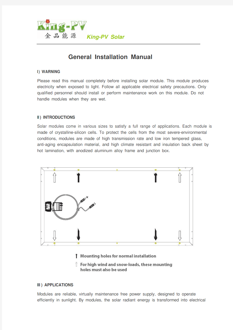
Solar modules come in various sizes to satisfy a full range of applications. Each module is made of crystalline-silicon cells. To protect the cells from the most severe-environmental conditions, modules are made of high transmission rate and low iron tempered glass, anti-aging encapsulation material, and high climate resistant and insulation back sheet by hot lamination, with anodized aluminum alloy frame and junction box.
III) APPLICATIONS
Modules are reliable, virtually maintenance free power supply, designed to operate efficiently in sunlight. By modules, the solar radiant energy is transformed into electrical
energy for using. Modules, usually be used as one fittings of PV solar system. A set of basic PV solar system is consisted of PV solar module, controller, inverter, and storage battery.
Modules can be used in roof PV solar systems, PV stations, building, and other electric generation application etc widely.
IV) CODES and REGULATIONS
The mechanical and electrical installation of PV systems should be performed in accordance with all applicable coded; including electrical codes, building coded, and electric utility interconnect requirements.
Requirements may also vary with system voltage, and for DC or AC application.
V) MECHANICAL INSTALLATIONS
a) Mounting site
Modules can be used on land except for corrosive salt area and sulfurous area.
Excluded applications include, but are not limited to, installations where modules are likely to come in contact with any salt water or where likely to become partially or wholly submerged in fresh or salt water, examples of which include use on boats, docks and buoys. Don’t install modules in a location where it would be immersed in water or continually exposed to water from a sprinkler or fountain etc.
Modules are designed for a maximum allowable design pressure of 50 pounds per square foot, about 5400Pa, which may correspond to a nominal wind speed of approximately 130 km/h in certain circumstances.
Actual maximum allowable wind speed may be influenced by module type, mounting configuration, location, and other factors. In no case should modules be exposed to pressures greater than 50 pounds per square foot of uniformly distributed wind, snow, or other loading.
Not install modules near naked flame or flammable materials.
When choosing a site, avoid trees, buildings or obstructions. Modules should be mounted to maximize direct exposure to sunlight and to eliminate or minimize shadowing. Even partial shadowing can substantially reduce module and system output. Furthermore, partial shadowing can elevate the shaded portion internal temperature, which may lower
output and shorten module life.
b) Orientation of installations
Modules may be mounted at any angle from a vertical orientation to a horizontal one. The appropriate fixed tilt angle and azimuth orientation should be used in order to maximize the exposure to sunlight.
Incorrect orientation of modules installation will result in loss of power output. Modules connected in series should be installed at same orientation and angle. Different orientation or angle may cause loss of power output due to difference of amount of sunlight exposed to the modules.
In the Northern Hemisphere, modules should face south, and in the Southern Hemisphere, modules should face north.
c) Module tilt angle
Modules produce the most power when they are pointed directly at the sun. For installations where modules are mounted to a permanent structure, modules should be titled for optimum winter performance. As a rule, if the PV system power production is adequate in the winter. It will be satisfactory during the rest of the year. The module tilt angle is measured between the modules and the ground.
d) Mounting
Use fasteners to fasten the modules to the mounting support structure. Modules should be bolted to support structures through mounting holes located in the frame’s back flanges only. Stainless-steel bolts, with nuts, washers, and locks washers, are recommended for module mounting. Creation of additional holes for mounting is not recommended and will
invalidate the warranty. Modules should not be mounted by supports at the ends.
Mounting support structure should withstand forces from wind and snowfall pressure etc. Mounting support structure should use proper materials and corrosive treatment.
Installation the modules should has proper ventilation. A clearance of 4.5 inches (about 115mm) or more behind the modules is recommended to permit air circulation and cooler module operation. Elevated temperatures lower operating voltage and power, and shorten module lifetime. Clearance of 1/4 inch (6.35mm) or more between modules is required to allow for thermal expansion of the frames.
VI) ELECTRICAL INSTALLATIONS
a) Blocking diodes
Blocking diodes can prevent nighttime battery discharging caused and prevent modules from loss of array output and being damaged or destroyed by reverse current flow.
Blocking diodes should be installed in series with each module or series string to prevent possible back flow of energy through the module(s) when modules or strings are connected in parallel or used in conjunction with a battery.
b) Overcurrent protection
Whenever necessary to comply with local codes, use a fuse or circuit breaker, rated for the maximum series fuse rating of the module and the system voltage.
Always fuse the connections at the battery for safety. Refer to the module rating label (on module) for recommended fuse size. Also, refer to the charge controller owners manual.
All electrical components should have ratings equal or greater to the system rating. Do not
exceed the maximum allowable system voltage as listed on the module label.
c) Grounding
All module frames should be grounded for safety. The support structure must also be grounded unless they are mechanically connected by nut and bolts to the grounded modules.
Attach a separate ground wire to grounding holes on modules frame with a self tapping screw. Module frame is provided with grounding holes. Stainless-steel bolts, with nuts, washers, and locks washers, are recommended for module grounding. The ground wire should be at least the same size as the electrical conductors, ground wires greater than 10AWG is recommended.
Assemble the recommended ILSCO grounding lug to the Aluminum frame using stainless steel M3, M4 or M5 screw and hardware as shown below. Note: there are two different size grounding holes, the smaller of which is being phased out. Further, build up of hardware for mounting the grounding lug are the same—except for the M3 & M4 screw, and added flat washer is mounted directly under the M3 & M4 screw head. The star washer is fitted directly under the grounding lug and makes electrical contact by
penetrating the anodized coating of the Aluminum frame. The screw assembly is further fitted with a flat washer, then a split lock washer and finally a nut to secure the entire assembly, as shown. Recommended torque of M3, M4 or M5 screw assembly is 0.8NM or 1.5NM.
d) Wiring
Modules are equipped with factory installed wires and quick connectors. Modules have been designed to be easily interconnected in series.
One module has a pair of male and female waterproof cables and connectors for electrical connection, that are pre-wired inside the junction box. The cables have obvious marks of the positive and the negative.
The connectors at the opposite end of these wires allow easy series connection of adjacent modules by firmly inserting the male connector of a module into the female connector of an adjacent module until the connector is fully seated.
For a series electrical connection, should connect positive (+) connector of the first module to the negative (-) connector of the following module. For a parallel electrical connection, should connect positive (+) connector of the first module to the positive (+) connector of the following module.
The cable typically used to interconnect the modules should be stranded or solid copper single-conductor type, rated sunlight resistant, for modules and module wiring that is exposed to weather, from 12AWG (4.0mm2) up to 14AWG(2.5mm2) gauge copper wire.
The maximum and minimum diameters of the cable that may be used with the cable connector are 8mm and 6mm respectively. A separate return wire or wires may be required to run the positive and negative terminations of the series string of modules to the load. Male and/or female connectors pre-attached to wires may be used at the string terminations for return wire connections and/or for source circuit box terminations. Modules have bypass diode(s) installed.
VII) MAINTENANES
It is not uncommon for a remote site to be checked but once per year. Under most conditions, normal rainfall is sufficient to keep the module glass clean.
Clean the glass with a soft cloth using mild detergent and water. Modules that are mounted, fiat ( 0°tilt andle) should be cleaned more often, as they will not self-clean as effectively as modules mounted at a 15°tilt or greater.
It is advisable to perform periodic inspection of the modules for damage to glass, backskin, frame and support structure. Check electrical connections for loose connections and corrosion. Check if mounting support structure and modules are loose. Check connections of cables, connectors, and grounding. Change modules must be the same kind and type, if need. Modules can operate effectively without ever being washed, although removal of dirt from the front glass can increase output. The glass can be washed with a wet sponge or cloth, wear rubber gloves for electrical insulation.
VIII) Safety precautions
Module installation and operation should be performed by qualified personnel only. Children should not be allowed near the solar electric installation.
Avoid electrical hazards when installing, wiring, operating and maintaining the module. Modules produce DC electricity when exposed to light and therefore can produce an electrical shock or burn. Modules produce voltage even when not connected to an electrical circuit or load. Modules produce nearly full voltage when exposed to as little as 5% of full sunlight and both current and power increase with light intensity. Do not touch live parts of cables and connectors. As an added precaution, use insulated tools and rubber gloves when working with modules in sunlight.
Fall of modules from high place will cause death, injury or damage. Do not drop module or allow objects to fall on module, never leave a module unsupported or unsecured. If a module should fail, the glass can break a module with broken glass cannot be repaired and must not be used.
When installing or working with module or wiring, cover module face completely with opaque material to halt production of electricity. Modules have no on/off switch. Modules when exposed to sunlight generate high voltage and are dangerous, modules can be rendered inoperative only by removing them from sunlight, or by fully covering the front surface with opaque cloth, cardboard, or other completely opaque material, or by working with modules face down on a smooth, flat surface when installing or maintaining.
Do not artificially concentrate sunlight on the module.
Modules can produce higher output than the rated specifications. Industry standard ratings are made at conditions of 1000W/㎡ and 25℃ cell temperature. Reflection from snow or water can increase sunlight and therefore boost current and power. In addition, colder temperatures can substantially increase voltage and power.
Modules are intended for use in terrestrial applications only, thus excluding aerospace or maritime conditions or use with sunlight concentration.
It is recommended that the module remains packed in the box until time of installation.
Work only under dry conditions, with a dry module and tools, since sparks may be produced, do not install module where flammable gases or vapors are present.
Do not drill holes into module frame as it will void warranty. Modules ate constructed frame as it will void warranty.
Handled with care, if the front glass is broken or if the polymer backskin is tom, contact with any module surface or the frame can produce electrical shock. Particularly when the module is wet, broken or damaged modules must be disposed of properly. Do not disassemble, bend, impact by sharp objects, walk on, and throw or drop etc. keep back surface free from foreign objects. Avoid sharp edges.
Use module for its intended function only follows all module manufacturers’ instructions. Do not disassemble the module, or remove any part or label installed by the manufacturer. Do not treat the back of the module with paint or adhesives.
If not otherwise specified, it is recommended that requirements of the latest local, national or regional electrical codes be followed.
Retain this installation manual for future reference.
IX) Notes
The electrical characteristics are within ±5 percent of the indicated values of Isc, Voc, and Pmax under standard test conditions (irradiance of 100mW/㎝2, AM 1.5 spectrum, and a cell temperature of 25℃(77°F).
Under normal conditions, a photovoltaic module is likely to experience conditions that produce more current and/or voltage than reported at standard test conditions. Accordingly, the values of Isc and Voc marked on this module should be multiplied by a factor of 1.25 when determining component voltage ratings, conductor ampacities, fuse sizes, and size of controls connected to the PV output
KING-PV TECHNOLOGY CO., LTD
Add.: No.18 Tangshan Road, Yongkang City, Zhejiang, Province, China Tel: +86-579-87153633/87158158
Fax: +86-579-87153560
E-mail: sales@https://www.doczj.com/doc/b55105429.html,
https://www.doczj.com/doc/b55105429.html,
Appendix:Panels data sheet
a) KPV195M-72 series, made up of 72pcs 125x125mm mono solar cells.
Item No. KPV165M-72 KPV170M-72 KPV175M-72 KPV180M-72 KPV185M-72 KPV190M-72 KPV195M-72
165W 170W 175W 180W 185W 190W 195W Ratedmax
power(Pmax)
42.0 42.6 42.6 43.2 43.2 43.2 44.5
voltage(V)
circuit
Open
5.28 5.36 5.52 5.6 5.76 5.91 5.77
current(A)
Short
circuit
35.0 35.5 35.5 36.0 36.0 36.0 36.5
power(V)
Voltage
max
at
power(A)
max
4.71 4.79 4.93
5.0 5.14 5.28 5.35
at
Current
Power tolerance: ±5%
Product size(mm) 1580x808x45
Weight(kg) 15.5
Maximum system voltage 1000VDC
NOCT 50℃
Max series fuse rating 15A
Operating temperature -40℃ to 85℃
All technical data at standard test condition AM=1.5 E=1000W/m2 TC=25℃
b) KPV260M-96 series, made up of 96pcs 125x125mm mono solar cells.
Item No. KPV200M-96 KPV210M-96 KPV220M-96 KPV230M-96 KPV240M-96 KPV245M-96 KPV250M-96 KPV255M-96 KPV260M-96 200W 210W 220W 230W 240W 245W 250W 255W 260W Ratedmax
power(Pmax)
55.82 56.4 57.6 57.6 57.6 59.2 59.8 59.8 60.1
voltage(V)
circuit
Open
4.86
5.01 5.13 5.36 5.60 5.45 5.51 5.62 5.72
current(A)
Short
circuit
power(V)
46.0 47.0 48.0 48.0 48.0 48.5 49.0 49.0 49.5
at
max
Voltage
power(A)
4.34 4.47 4.58 4.79
5.0 5.05 5.10 5.20 5.29
at
Current
max
Power tolerance: ±5%
Product size(mm) 1575x1082x50
Weight(kg) 21.5
Maximum system voltage 1000VDC
NOCT 50℃
Max series fuse rating 15A
Operating temperature -40℃ to 85℃
All technical data at standard test condition AM=1.5 E=1000W/m2 TC=25℃
c) KPV250P-60 series, made up of 60pcs 156x156mm poly solar cells.
Item No. KPV200P-60 KPV210P-60 KPV220P-60 KPV225P-60 KPV230P-60 KPV235P-60 KPV240P-60 KPV245P-60 KPV250P-60 200W 210W 220W 225W 230W 235W 240W 245W 250W Ratedmax
power(Pmax)
34.2 34.8 35.4 35.4 36.0 36.0 36.0 37.2 37.8
voltage(V)
circuit
Open
7.86 8.11 8.36 8.55 8.59 8.77 8.96 8.74 8.85
current(A)
Short
circuit
power(V)
28.5 29.0 29.5 29.5 30.0 30.0 30.0 30.0 30.5
at
max
Voltage
power(A)
max
7.02 7.24 7.46 7.63 7.67 7.83 8.0 8.17 8.20
at
Current
Power tolerance: ±5%
Product size(mm) 1650x992x50
Weight(kg) 19.5
Maximum system voltage 1000VDC
NOCT 50℃
Max series fuse rating 15A
Operating temperature -40℃ to 85℃
All technical data at standard test condition AM=1.5 E=1000W/m2 TC=25℃
d) KPV300P-72 series, made up of 72pcs 156x156mm poly solar cells.
Item No. KPV240P-72 KPV250P-72 KPV260P-72 KPV270P-72 KPV280P-72 KPV285P-72 KPV290P-72 KPV295P-72 KPV300P-72 240W 250W 260W 270W 280W 285W 290W 295W 300W Ratedmax
power(Pmax)
41.4 42.0 42.6 43.2 43.2 44.6 44.6 45.3 45.3
voltage(V)
circuit
Open
current(A)
8.01 8.11 8.21 8.31 8.41 8.55 8.61 8.72 8.79
circuit
Short
power(V)
35.0 35.5 35.5 36.0 36.0 36.0 36.0 36.5 36.5
max
at
Voltage
power(A)
6.86
7.04 7.33 7.5 7.78 7.92
8.05 8.08 8.22
at
Current
max
Power tolerance: ±5%
Product size(mm) 1957x992x50
Weight(kg) 22.5
Maximum system voltage 1000VDC
NOCT 50℃
Max series fuse rating 15A
Operating temperature -40℃ to 85℃
All technical data at standard test condition AM=1.5 E=1000W/m2 TC=25℃
一、工程概况 1.工程名称:【】 2.项目规模:【 5MW】 3.工程地点:【】 二、编制依据 1.施工图纸 2.组件生产厂家安装说明书 3、《光伏发电站施工规范》(GB50794-2012) 4、《光伏发电工程验收规范》GB50796-2012) 三、施工管理目标 1.质量目标 组件无破损,一次验收合格率达100%。 2. 安全目标 确保无重大安全事故发生,轻伤频率控制在1%以内。 四、施工准备 1、、技术准备 ①认真审核、熟悉施工图纸,了解组件的排列组别。 ②对施工班组进行有针对性的技术、安全交底。 ③根据工程实际情况划分作业区域,合理调配作业人员。 2、安装前准备 ①组件外观检查。 在视觉直观下,组件应平整,周边无开胶、裂纹等缺陷,色差、尺寸、铭牌参数应符合要求,偏差较大的组件应及时联系相关人员进行处理。 ②支架已调整,不存在高、低或波浪型的起伏,直线度良好。
复查支架安装质量符合下表要求: ③ 3、劳动力计划 根据作业面积分部特点人员计划安排如下: 五、组件安装 组件在搬运、摆放、紧固螺丝时均要轻拿轻放,严防磕碰。 1. 组件安装前应复查支架的平整度,若目测发现有明显的高差,严禁进行安装。须 经专业人员调整后报验合格才能进行安装。 2.组件开箱前,先检查组件箱体外包装,确认外包装纸箱无破损后再进行开箱。如
外包装有损坏,则从破损处打开。打开后须认真检查,确认组件是否存在破损现象,如发现破损及时向相关人员汇报,并停止继续开箱。 3.在破除外包装时,应避免刀片划伤组件外层的保护膜。开箱后包装垃圾集中放置,避免环境污染。 4.测量太阳能电池板在阳光下的开路电压,电池板输出端与标识正、负值应吻合。 5. 组件的倒运装卸必须轻拿轻放,尽量减少箱体在运输过程中的震动、摇摆等不利 因素,且晃动幅度﹤±2°。 6. 安装过程中组件要轻拿轻放,搬动时严禁组件直接与地面接触,防止硬物对组件 造成点损伤的隐患。组件确需依靠或平放时不得超过2块。 7. 组件安装过程中,安装人员严禁依靠、抓扶横梁、斜梁,避免产生变形对组件造 成应力损伤。 8. 组件的安装顺序应由下至上,依次安装。下排组件安装完成后,上排组件在安装 时应与定位块保持一定距离,避免在安装后,取出定位块时损伤组件。 9. 组件安装完成后应进行自检,看组件有无裂纹、层次不齐、防滑垫片卷边、上、 下超出卡钳或达安装要求的其它问题,并及时整改。 10. 安装组件搭设的平台一定要稳固,防止颤动、跌滑。 11. 按照图纸要求安装每组组件数量,不得随意更改。 组件安装时应拉水准线,并以上侧组件底端为基准,进行水平控制。 12.组件之间的接线应符合以下要求: ①.组件连接数量和路径应符合设计要求。 ②.组件间接插件(公母插头)应连接牢固。 ③.外接电缆同插接件连接处应搪锡。 ④.组串连接后开路电压和短路电流应符合设计要求。 ⑤.电线不得放置在檩条槽内(防槽内积水),用带钢芯黑色绑线绑扎在檩条的侧
光伏组件安装作业指导书 编制: 审核: 批准: 2014年10月7日 目录 1. 工程概况 2.编制依据
3.施工管理目标 4. 施工准备 5.组件安装 6.质量保证措施 7.施工安全文明管理措施 一、工程概况 本工程是25.245MWp太阳能发电项目,所发电并网时要求高,保证设备质量特别重要,无论是在建设安装质量上还是工程进度及其他要求都必须做到最好。必须使系统具备足够的强度、刚度和使用可靠性,达到排列美观的设计效果,最后在工程规定的工期内一次性通过验收。
二、编制依据 1.《低压配电设计规范》GB50054-95 2.《建筑结构荷载规范》(GBJ50009-2001) 3.设计院设计蓝图的相关要求 4.我国现行光伏行业相关的施工验收规范和操作规程 三、施工管理目标 1.质量目标 组件无破损,一次验收合格率达100%。 2. 安全目标 确保无重大安全事故发生,轻伤频率控制在1‰以内。 四、施工准备 (一)、技术准备 1.认真审核、熟悉施工图纸,了解组件的排列分别。 2.对施工班组进行有针对性的技术、安全交底。防止组件破裂为重点防范内容。3.根据工程实际情况划分作业区域,合理调配作业人员。 (二)、安装前准备 1. 组件外观检查。 在视觉直观下,组件应平整,周边无开胶、裂纹等缺陷。 2. 支架已调整不存在高、低或波浪型的起伏,直线度良好。 3. 装配使用的卡钳已到位,满足组件安装使用。 (三)、劳动力计划 根据作业面积分部特点人员计划安排如下: 五、组件安装
由于薄膜式太阳能电池板易碎的特性,组件在搬运、摆放、紧固螺丝时均要轻拿轻放,严防磕碰。 1. 组件安装前应复查支架的平整度,若目测发现有明显的高差,严禁进行安装。须经专业 人员调整后报验合格才能进行安装。 2.组件开箱前,先检查组件箱体外包装,确认外包装纸箱无破损后再进行开箱。如外包装有损坏,则从破损处打开。打开后须认真检查,确认组件是否存在破损现象,如发现破损及时向相关人员汇报,并停止继续开箱。 3.在破除外包装时,应避免刀片划伤组件外层的保护膜。开箱后包装垃圾集中放置,避免环境污染。 4.测量太阳能电池板在阳光下的开路电压,电池板输出端与标识正、负值应吻合。 5.组件的倒运装卸必须轻拿轻放,尽量减少箱体在运输过程中的震动、摇摆等不利因素, 且晃动幅度﹤±2°。 6.安装过程中组件要轻拿轻放,搬动时严禁组件直接与地面接触,防止硬物对组件造成点 损伤的隐患。组件确需依靠或平放时不得超过2块。 7.组件安装过程中,安装人员严禁依靠、抓扶C型钢,避免C型钢产生变形对组件造成应 力损伤。 8.组件的安装顺序应由下至上,依次安装。下排组件安装完成后,上排组件在安装时应与 定位块保持一定距离,避免在安装后,取出定位块时损伤组件。 9.组件安装完成后应进行自检,看组件有无裂纹、层次不齐、防滑垫片卷边、上、下超出 卡钳或达安装要求的其它问题,并及时整改。 10.安装组件搭设的平台一定要稳固,防止颤动、跌滑。 11. 按照图纸要求安装每组组件数量,不得随意更改。 六、质量保证措施 牢固树立:质量第一的工作思想,要求每一道工序、每一个部位都必须是上道工序为下道工序提供精品,把质量责任分解到各个岗位、各个环节,凡事有章可循,有据可查。通过全方位、全过程的质量动态管理来保证质量。并按照ISO9000系列标准建立起有效的质量保证体系,并制定了相应的质量管理制度,最大限度地发挥每个部门、每个岗位和每个人的作用。 七、施工安全文明管理措施 1、安全管理保证制度 1.1 安全教育制度
目录 1.工程概况 (1) 2.编制依据 (1) 3.主要工程内容 (1) 4.参加作业人员的资格和要求 (1) 5.作业所需的工器具 (1) 6.作业前应做的准备工作 (1) 7.支架制作安装方案 (2) 8.光伏板安装 (5) 9.防雷接地 (6) 10.电缆敷设 (7) 11.试验方案 (8) 12.安全文明施工措施 (8)
1.工程概况 东营(胜利)城卫分布式光伏示范区20兆瓦项目(以下简称本工程)规划容量为20MWp。项目建设地位于山东省东营市垦利区胜利油田孤东十万亩土地开发项目区东营金润盐化有限责任公司初级蒸发区水池,坐标为北纬37°56'29.8",东经119°0'21.7",海拔高度0m,项目规划容量为20MWp。本工程装机容量为20MWp,采用分区发电、集中并网方案。光伏组件是光伏发电系统的核心部件,其各项参数指标的优劣直接影响着整个光伏发电系统的发电性能。通过比较,本工程电池组件选270Wp多晶双玻硅电池组件,逆变器选用1250kW光伏并网逆变器。光伏组件采用固定式安装形式,结合建设方意见,电池方阵的固定倾角为26。本工程系统综合效率取80%,由计算可得,本工程25年总发电量约为64749万kW·h,25年年平均发电约2589.96万kW· h,平均年利用小时数为:1112小时。 本工程容量为20MWp,本期建设开关站一座,站内35kV侧采用单母线接线方式,并建设1回35kV出线接至系统侧。本期将16个发电单元组按照每8个发电单元组为一组,通过2回35kV集电线路接入35kV母线上,再通过1回35kV出线接入系统。本期整个20MWp光伏并网电站系统由16个约为1.25MWp的光伏并网发电单元组成,每个发电单元由1套1250kW光伏并网逆变器组成,每台逆变器输出电压为360V三相交流电,通过断路器接到升压变压器的低压绕组上,经1250kVA箱式变压器升压至35kV高压,将8台变压器经35kV集电线路并联后,通过高压开关柜接入35kV配电室35kV母线上,共设计2回路。35kV配电装置采用屋内布置,成套金属铠装开关柜,开关柜单列布置,开关柜均采用"下进下出"接线方式。无功补偿装置的连接变压器室外布置,消弧线圈接地变兼站用变布置在35kV配电室外。 2. 编制依据 2.1江苏谦鸿电力工程咨询有限公司设计施工图
太阳能路灯安装手册 一、选址 1.根据路身和灯具光源位置,选择灯具光源朝向,满足路面最大照射面积 2.太阳能路灯必须安装在光照充足且太阳能板迎光面上全天没有遮挡阴影。 3.太阳能灯具要尽量避免靠近热源,以免影响灯具寿命。 4.环境使用温度:-20至55摄氏度。以比较冷的环境下,应适当加大蓄电池容量。 5.太阳能板上方不应有直射光源。以免使灯具控制系统误识别而导致误操作。 6.太阳能路灯安装位置下方不能有其他设施(如电缆、管道等),上方不能有高压线, 架空线等。 7.安装地点必须排水顺畅,如果距离安装地点10米内有河流或水坑等低洼积水点,则 地基最少必须高于积水点最高水位, 二、地基 1.地基预埋件(地笼)安装: 2.地基坑开挖: 依据施工图纸要求在布点位置进行基坑开挖工作,并依据图纸把握好基坑距路边缘的距离、基坑的宽度、深度,基坑不能过宽、过浅,也不能过窄过深。在地下无管线等设施时可以采用机械开挖基坑,如地下有不确定的管线等设施时,必须采用人工开挖的方式。 注意事项:勘察情况,如果地表1米2皆是松软土质,那么开挖深度应加深;在立灯具的位置开挖符合图纸标准的坑,进行预埋件的定位浇注。预埋件放置在方坑正中,PVC穿管线放置在预埋件正中间,另一端放置在蓄电池储存处。注意保持预埋件、地基与原地面在同一水平面上(或螺杆顶端与原地面在同一水平面上,根据场地需要而定),有一边要与道路平行;这样方可保证灯杆树立后端正而不偏斜;然后以C20混凝土浇筑固定。 蓄电池填埋处不得有积水情况发生,地埋电池坑大约0.5m*0.5m*1m(长度和宽度因地埋箱规格而异,深度因地域而异,保证在当地冻层下 方) 3.地基浇筑: 1、混凝土粘稠度应适中,不能过稀,也不能过稠; 2、基坑在浇筑前应做好准备工作,例如基坑的高度、有无杂物,若基坑有管线应提前申报领导做好适当处理; 3、施工预埋前螺杆上裹上胶布;防止浇灌水泥污染螺杆,妨碍上螺丝。 4、混凝土凝固过程中,要定时浇水养护,待混凝土完全凝固(3-5天),才能进行吊灯安装; 5.下预埋穿线管(保护管),应设专人及时对基础出线孔对准蓄电池出线孔,上端口应位于预埋件中部,且高于混凝土预埋件5厘米(以免进水),尽量避免预埋穿线管打弯,其内径不得小于所穿钢丝软管外径的1.5倍,若保护管有弯曲时,不得小于2倍,要尽量避免
《客户管理系统》安装配置说明书 一、开发平台安装配置 下面的所有程序的安装都是在Windows XP + SP2或Windows 2000 Advance Server + SP4操作平台上完成。 1、JDK1.4安装与环境配置: (1)、前言 JDK(Java Development Kit )是一切java应用程序的基础,可以说,所有的java应用程序是构建在这个之上的。它是一组API,也可以说是一些java Class。目前已经正式发布的最新版本是JDK1.5。 (2)、下载,安装 下载地址为JA V A官方站点:https://www.doczj.com/doc/b55105429.html,/j2se/1.4.2/download.html,.点击“Download J2SE SDK”: 这时点―Accept‖,继续: 下面列出了各个平台下的JDK版本,其中Windows版有两种安装方式,一种是完全下载后再安装,一种是在线安装,我们选择第一种:
下载完成后,双击图标进行安装,安装过程中可以自定义安装目录等信息,例如我们选择安装目录为D:\jdk1.4。 (3)、配置JDK环境变量: 右击“我的电脑”,点击“属性”: 选择“高级”选项卡,点击“环境变量”:
在“系统变量”中,设置3项属性,JA V A_HOME,PATH,CLASSPATH(大小写无所谓),若已存在则点击“编辑”,不存在则点击“新建”: JA V A_HOME指明JDK安装路径,就是刚才安装时所选择的路径D:\jdk1.4,此路径下包
括lib,bin,jre等文件夹(此变量最好设置,因为以后运行tomcat需要依靠此变量);Path使得系统可以在任何路径下识别java命令,设为: %JA V A_HOME%\bin;%JA V A_HOME%\jre\bin CLASSPATH为java加载类(class or lib)路径,只有类在classpath中,java命令才能识别,设为: .;%JA V A_HOME%\lib;%JA V A_HOME%\lib\tools.jar (要加.表示当前路径) %JA V A_HOME%就是引用前面指定的JA V A_HOME。 “开始”->“运行”,键入“cmd”: 键入命令―java -version‖,出现下图画面,说明环境变量配置成功:
安装手册 请在使用或者安装贝达系列太阳能光伏组件之前仔细阅读本手册。该光伏组件在光照情况下会产生电流电压。请遵守所有的电器安全防范措施。只有有资质的人员才可以安装或者维修该组件产品。请不要损坏太阳能电池组件或者造成太阳能电池组件表面的刮伤。潮湿的环境会有导电的危险,请不要在组件潮湿的时候对组件做任何操作。 1.安全预防措施 1.1光伏组件没有开关。只能通过将光伏组件挪离光照或者用布、硬纸板或者完全不透 光的材料遮挡,或者将组件正面放置在光滑、平坦的表面上才会使组件停止工作。 1.2光伏产品在光照情况下会产生直流电,所以会有电击或者烧伤的危险。即使在没有 连接负载或者外电路的情况下,组件也会产生电流电压。在光照大于5%的情况下,组件就会产生最大电压,随着光照强度的增大,产生的电流和功率也会不断增加。所以在阳光下对组件动作时,请使用绝缘工具,同时佩戴橡胶手套。最好,在操作过程中,把电池板表面用不透光材料覆盖。 1.3组件产生的功率可能会高于铭牌上的额定标称。工厂标准的额定输出是在光强 1000watts/m2,温度25℃,大气质量1.5的情况下测量的。雪和水的反射也会增加光强,因此会造成电流和输出功率的增大。另外,温度低于25℃时组件的电压和功率也会相应的增长。 1.4贝达太阳能电池组件的表面为钢化玻璃,但是操作时仍要小心,不合理的操作会造 成组件表面的钢化玻璃破碎。如果正面的玻璃破碎或者背面的聚合物烧坏,任何和组件表面或者铝合金边框的接触都可能造成电击,尤其在组件潮湿的情况下。破损的组件必须由专业人员妥善处理。 1.5贝达太阳能电池组件的设计是仅适用于陆地的,所以不能在太空、海洋或者聚光环 境使用。除了上述环境,组件也不能被安装在有可能接触到任何盐水或可能成为部分或全部淹没在淡水或海水的情况,建议把组件安装在离海最少500m的地方。 2.守则和条例 光伏组件的机械安装和电气安装应该参照相应的法规,包括电气法、建筑法和电力互联需求。这些条例随着安装地点的不同而不同,例如建筑屋顶安装、汽车应用等。要求也可能随着安装系统电压,使用直流或者交流的不同而不同。具体条款请联系当地的权威机构。 3.机械安装 3.1可以将组件按照从水平到垂直的任何一个角度安装。 3.2合适的安装倾角和面向的方位角应该以组件产品得到最多的光照为标准。 3.3应该通过组件背面的安装孔将组件安装在支架上。
管理平台软件 安装指南
目录 1 安装准备 (3) 1.1软件获取 (3) 1.2运行环境要求 (3) 1.3软件清单 (4) 1.4默认端口 (4) 1.5如何获取帮助 (4) 2 安装软件 (5) 2.1服务器优化 (5) 2.2CMS管理服务器的安装 (6) 2.3CMS管理服务器的卸载 (14) 2.3.1 清理服务 (14) 2.3.2 卸载程序 (15) 2.4SVR功能服务器程序的安装 (16) 2.5CSC控制客户端的安装 (21) 2.6手机客户端下载 (25) 3 数据备份 (26) 3.1P OSTGRE SQL数据库 (27) 3.1.1 数据备份 (27) 3.1.2 数据库还原 (30) 3.2数据库升级 (32) 4 常见安装问题 (35) 4.1浏览器控件安装 (35) 4.2如何修改数据库访问端口 (35) 4.3管理平台安装后TOMCAT服务无法启动 (36) 4.4K MS如何修改挂载盘符 (36)
1安装准备1.1软件获取 1.2运行环境要求 ●硬件环境 CMS服务器: CMS_V4.X版本: CPU:Intel Xeon E5-2620 v2 2.1GHz 内存:8G DDR3 网卡:Intel 1000M NIC*2(安装最新网卡驱动) 其他服务器: CPU:Intel Xeon E5-2620 v2 2.1GHz 内存:8G DDR3 网卡:Intel 1000M NIC*2(安装最新网卡驱动) 客户端: CPU:Intel 四核,1.8GHz以上内存:4G DDR2 网卡:Intel或者RealTek的100Mbps以上的网卡(安装最新网卡驱动) ●软件环境 CMS服务器: 操作系统:Windows Server 2008 R2 x64 JDK:Java Platform, Standard Edition, JDK 8 Update45
目录 一、悬吊零件 1 TB/T2075.1-2002 接触线吊弦线夹 JL02-89 (1) 2 TB/T2075.2-2002 承力索吊弦线夹 JL02(L)-89 (2) 3 TB/T2075.3-2002 横承力索线夹 JL23-89 (3) 4 TB/T2075.4-2002 双横承力索线夹 JL24-89 (4) 5 TB/T2075.7-2002 杵座鞍子 JL17-89 (5) 6 TB/T2075.8-2002 钩头鞍子 JL18-89 (6) 7 TB/T2075.12-2002 悬吊滑轮 JL11-96 (7) 8 TB/T2075.16-2002 定位环线夹 JL21-89 (8) 9整体吊弦 JL(GT)02-2002 (9) 二、定位零件 10 TB/T2075.13-2002 定位线夹 JL01-89 (10) 11 TB/T2075.14-2002 支持器 JL09-89 (11) 12 TB/T2075.15-2002 长支持器 JL10-89 (12) 13 TB/T2075.17-2002 定位器 JL63-89 (13) 14限位定位器 JL(GT)04-01 (14) 三、连接零件 15 TB/T2075.23-2002 双耳连接器 JL32-89 (15) 16 TB/T2075.24-2002 定位环 JL12-89 (16) 17 TB/T2075.25-2002 长定位环 JL13-89 (17) 18 TB/T2075.26-2002 套管双耳JL14-89 (18) 19 TB/T2075.27-2002 套管铰环 JL16-89 (19) 20 TB/T2075.29-2002 承力索接头线夹 JL8803-89 (20) 21组合承力索座 JL18(GT)-98 (21) 四、锚固零件 22 TB/T2075.5-2002 接触线中心锚结线夹 JL03-89 (22) 23 TB/T2075.6-2002 承力索中心锚结线夹 CZM(70-120)-98 (23) 24 TB/T2075.31-2002 杵座楔型线夹 JL26-89 (24) 25 TB/T2075.32-2002 双耳楔型线夹 JL27-89 (25) 26 TB/T2075.35-2002 承力索终端锚固线夹 JQJL27-89 (26) 五、支撑零件 27 TB/T2075.39-2002 旋转腕臂底座 JL28-89 (27)
Add :Xu Xiake Huangtang Industrial Park, Jiangyin, Jiangsu, China Zip: 214407 1 Installation | Safety instructions | Maintenance Photovoltaic modules user manual Please carefully read the following installation and safety instructions. Non-compliance with these instructions may void the module warranty. Purpose of this guide This guide contains information regarding the installation and safe handling of Hareon photovoltaic modules (hereafter referred to as "modules"). All instructions should be read and understood before attempting installation. If there are any questions, please contact your dealer or Hareon for further information. The installer should conform to all safety precautions in the guide when installing modules. Before installing a solar photovoltaic system, the installer should become familiar with the mechanical and electrical requirements for photovoltaic systems. Keep this guide in a safe place for future reference. General | Installing solar photovoltaic systems requires specialized skills and knowledge. The installer assumes all risk of injury, including risk of electric shock. Module installation should be performed only by qualified persons. | All modules come with a permanently attached junction box and #12 AWG (4 mm 2) wire terminated in PV connectors. Your dealer can provide additional extension cables to simplify module wiring. | Exercise caution when wiring or handling modules exposed to sunlight. | When disconnecting wires connected to a photovoltaic module that is exposed to sunlight, an electric arc may occur. Arcs can cause burns, start fires or otherwise create safety problems. Exercise caution when disconnecting wiring on modules exposed to sunlight. | Photovoltaic solar modules convert light energy to direct-current electrical energy, and are designed for outdoor use. Proper design of support structures is the responsibility of the system designer and installer. | Modules may be ground mounted, pole mounted, or mounted on rooftops. Do not attempt to disassemble the module, and do not remove any attached nameplates or components. Doing so will void the warranty. | Do not apply paint or adhesive to the module. Do not use mirrors or other hardware to artificially concentrate sunlight on the module. | When installing modules, observe all applicable local, regional and
重大 综合 √一般 林州市横水镇60MWp光伏发电项目接地装置安装施工方案 编制: 审核: 批准:
目录 一、施工内容................................ 错误!未定义书签。 二、工程概况 (1) 三、施工工艺流程图.......................... 错误!未定义书签。 四、施工准备................................ 错误!未定义书签。 五、施工要求 (2) 六、施工方法 (3) 七、主要工程质量 (4) 八、质量控制 (4) 九、安全措施 (5) 十、安全文明施工措施 (6) 十一、质保要求 (7) 十二、安全控制 (7) 十三、控制措施 (8)
一、 施工内容 开关站接地网及光伏场区接地网焊接、敷设。 二、 工程概况 本期工程规划用地面积约228.2905hm2,长约2200m ,南北最大宽约2863m ,场址区域地形开阔,光伏电板区域分布零散,现场有少量雨水冲沟,北高南低,为荒山坡地。 本工程采用分块发电、集中并网的方式,装机容量为60.48MWp 。多晶硅光伏组件均采用固定方式安装在固定支架上(最佳倾斜角320o)。 三、 施工工艺流程图 四.施工准备 1.材料及工具 ①根据施工图做好扁钢、接地极等材料的计划,并报给物资管理部按计划采购。 施工准备 测量放样 沟(槽)开挖 接地网敷设 质量检查 处理存在问题 接地网敷设 沟(槽)回填 接地电阻测试
②材料进场必须具备相应的检测合格资料,并报监理认可。 ③准备好合格焊条,作好焊条贮存工作,严防受潮。 ④施工机具配备,柴油发电机、三轮车、打桩机、交流电弧焊机、十字镐、 铁铲、铁撬、电锤、砂轮切割机、角磨机等。 2.作业条件 ①施工场地符合施工要求。 ②施工前对施工人员进行安全培训技术交底,让施工人员了解和熟悉设计及施工规范要求。 ③检查好施工机械(或工具),保证满足施工要求。 ④做好施工人员安排计划,配置劳动力。 3施工技术准备 ①技术准备 1)施工图纸的审核和学习。 2)施工前技术交底和安全交底的学习。 3)施工前的工器具的使用培训。 ②要求进度:按工程施工进度完成此项任务。 五、施工要求 1.施工前必须熟悉设计图纸和有关规范。 2.接地装置的金属构件应热镀锌防腐,水平接地网采用50mm×5mm镀锌扁钢,电池组件支架接地引下线采用双边50mm×5mm镀锌扁钢分别引接主网的不同边。 3.全站接地以水平接地为主,垂直接地为辅的接地方式垂直接地级打入地中,上端部与水平接地体相连接。本工程冻土层为1170mm,根据规范要求接地网深埋在冻土层地区应敷设在冻土层以下。 4.水平接地体与建筑物外墙间距一般不少于1.5米,通常2~3米,接地网的外缘闭合,外缘个角应做成圆弧形,接地网内应敷设水平均压带,对接地网的外缘经常有人出入的走道应敷设水平“帽檐式”均压带。为减少相邻接地体的屏蔽作用,垂直接地极及水平接地带的间距不宜小于5米。 5. 全场系统接地干线采用-50x5热镀锌扁钢;垂直接地极采用L50x50x5,L=2500mm热镀锌角钢;交流汇流箱、逆变器、美式箱变接地干线-50x5热镀锌扁钢,
支柱装配作业指导书 编制孙正成 审核 批准
支柱装配作业指导书 1. 适用范围 本作业指导书适用于时速200公里及以下标准电气化铁路接触网工程支柱装配(腕臂安装、定位安装和拉线制作安装)的施工。 2. 作业准备 熟悉设计文件,认真审核施工图纸,对采用的新技术、新材料编制专项的作业指导书并现场进行技术交底;检查支柱状态符合设计要求且已稳定,腕臂计算软件已进行初始化调试、试验和验证;以设计(或线路开通时)的线路轨道标高为基准在支柱上标注轨面红线,轨道线路中心已达标或者已取得线路中心标准交桩测量资料;支柱已按要求整正到位;配备测量人员、技术人员及现场作业人员;准备好梯车、滑轮、线坠、钢卷尺、丁字尺、支柱倾斜仪、道尺、水平尺、扭矩扳手、电工工具、安全带、微机或手提电脑等工器具。所有支柱装配施工所需材料全部进场,检测合格并对绝缘子做耐压试验。 3. 技术要求 3.1电力金具、接触网零配件运达现场应进行检查,其质量应符合《电力金具通用技术条件》(GB2314)、《电气化铁道接触网通用技术条件》(TB/T2073)和《电气化铁道接触网零部件》(TB/T2075)及有关标准的规定。 3.2腕臂安装高度应符合设计要求,安装时应采用力矩扳手紧固,
紧固力矩要求符合设计要求。紧固件要按设计要求配齐螺帽、垫片、止动垫片、弹簧垫圈等,新产品应符合该产品安装使用说明书的要求。 3.3开口销安装后的劈开角度不应小于60°,开口后不得有裂纹、断裂现象。销钉安装时垂直放置的应钉帽在上,水平放置的两销钉头应相互倒置安装。 3.4锚柱拉线宜设在锚支的延长线上,在任何情况下严禁侵入基本建筑限界,当地形受限时,应按设计要求施工。 3.5板型号、抗压极限强度、埋设深度及锚板拉杆规格均应符合设计要求。锚板拉杆与拉线在一条直线上,锚板垂直于拉线。锚板拉杆与地面夹角宜为45o,特殊困难地段不得大于60o,但锚板埋设深度应按设计要求相应加深。 3.6拉线角钢水平,应与支柱密贴,连接件镀锌层无脱落和漏锌现象,钢绞线拉线无锈蚀现象并涂防腐油防腐。回头绑扎牢固。 3.7锚柱拉线施工允许偏差应符合表3.7规定。 表3.7 锚柱拉线允许偏差(mm)
光伏组件安装使用说 明
晶硅光伏组件 安装使用说明手册 编制: 审核: 批准: 发布日期:实施日期: 1 目的 1.1 本手册包括晶体硅光伏组件(以下简称组件)的安装、操作、使用方法及注意事项,在安装之前请务必认真阅读本手册,以免承担质保责任。那些不正确
安装、运行、使用和维护所造成的功率损失、太阳能光伏组件损坏、人员伤亡或者额外花费,XX太阳能将不承担任何责任。 2 工作内容 2.1安全防范 2.1.1 组件必须由专业资格的人员来安装,确保完全理解在安装组件过程中存在的可能或潜在风险。 2.1.2 安装组件时,应遵守所有地方、地区、国家和国际的相关的法律、法规,必要时应先获得相关的许可证明。 2.1.3 为了您的安全,不要在恶劣的环境下安装或操作组件,包括强风和阵风天气或是潮湿结霜的屋顶表面。 2.1.4 屋顶的光伏系统只能被安装在经过建设专家或工程师评估的建筑上,有正式的完整结构分析结果,并被证实能够承受额外的系统支架压力和光伏组件自身重量。 2.1.5 单个太阳能光伏组件在阳光直射下可产生30V 以上的直流电压,接触30V 或更高的直流电压将存在潜在危险。正确的操作,尽可能避免此危险的发生。 2.1.6 不要在有负载的情况下断开连接线。 2.1.7 若组件正面玻璃破损,或背板出现裂口或破洞,与任何组件表面或边框接触都可能导致电击。 2.1.8若组件边框锋利或表面玻璃破损可能会导致划伤。 2.1.9 安装时请不要携带珠宝等贵金属,以免戳穿组件表面或边框可能导致触电。 2.2搬运注意事项 2.2.1不得擅自拆卸组件。 2.2.2不得在组件上乱涂。 2.2.3不要在组件上行走。 2.2.4不要在组件上粘贴其他名牌。 2.2.5不要直接托着接线盒的线缆搬运组件。 2.2.6不要用镜子或透镜聚焦阳光照射到组件上。 2.2.7用不透光的材料盖住储藏在户外的组件,以免被阳光直射。 2.3环境条件
光伏组件拆除方案 1、施工准备 1、技术准备: 编制支架拆除专项施工方案,对施工单位进场拆除工作人员进行安全技术交底。支架拆除过程中不应破坏支架防腐层。 2、人员准备: 应成立拆除工作小组,组织有经验的技术负责人、拆除工人、设立专职安全员。 3、现场准备 1)提供空余场地供所拆除的支架堆放。拆除完的檩条、拉杆、斜支撑、斜梁、前后立柱连接件应分类码放整齐,及时运回项目部存放。 2)疏通现场道路,保证拆完的支架能及时运输。 2、组件拆装搬运要求: 1)工人穿戴好个人劳动防护用品,不得触摸金属带点部位,不得佩戴金属首饰。 2)拆卸组件前必须先断电,再分断快接头,捆扎好四平方线后做好防水措施。组件正负极接线使用胶布将其固定在太阳能板背面,然后进行组件拆卸。 3)拆卸时严格按照规定,两人各站一边,一人拆卸螺丝,一人扶着组件,防止拆开后组件倾倒。拆下的组件靠在支撑物上时,避免组件受到支撑物划伤。 4)组件搬运时,要使组件垂直放置;两个人同时用双手抓住边框,禁止拉扯导线。移动组件过程中避免激烈颠簸和震动。 5)严禁在组件上踩踏,不要使组件遭受撞击。严禁手指接触玻璃面,避免在玻璃面上留下指印。 6)禁止雨天进行拆卸,禁止划伤背板。 7)不要在组件上放置其他物品。 8)不要尝试分解组件,不要拆除组件上的任何铭牌。 9)记录好拆卸的组件所属区域位置,记录拆卸顺序,对组件做好编号并拍摄条形编码。3、组件包装前做好下列检查: 1)外观检查应完好无损。 2)检查型号、规格应符合取样要求。 3)将拍摄的条形编码提供给商务部,让厂家提供组件相关资料(包含曲线图,合格证明,实验资料等)并发函要求旁站。 4、组件包装转运要求:
西京学院校园信息化平台安装部署说明书 (过渡版本)
文件修订历史 模板修订历史
1安装规划 (5) 2系统概述 (5) 2.1硬件 (5) 2.2软件 (5) 2.3安装顺序 (5) 3数据库服务器安装设置(1台) (6) 3.1操作系统注意事项 (6) 3.2 安装及设置OraCIe(企业版) (7) 3.3拷贝数据 (7) 3.4创建数据库及数据库用户 (7) 3.5数据库用户授权及创建作业任务 (8) 4应用服务器安装设置(4台) (8) 4.1操作系统注意事项 (8) 4.2安装及设置IIS6.0 (9) 4.3 安装.net framework 2.0 (11) 4.4安装OraCIe客户端 (11) 5数据库接收(同步)程序安装设置 ........................... 错误!未定义书签。 5.1拷贝程序文件 ........................................... 错误!未定义书签。 5.2配置运行参数 ........................................... 错误!未定义书签。 5.3重新启动程序 ................................ 错误!未定义书签。 6信息化平台系统安装设置 .................................. 错误!未定义书签。 6.1拷贝程序文件 ........................................... 错误!未定义书签。 6.2配置运行参数 ........................................... 错误!未定义书签。 6.3重新启动程序 ................................ 错误!未定义书签。 6.4用户管理系统 (12) 7信息化系统安装设置 (19) 7.1拷贝文件 (19) 7.2创建IIS服务 (19)
光伏电站施工方案(专业版) 一、测量放线及定点:测量人员以控制网为基础进行光伏组件基础放点,按照图纸准确放出桩基基础高程、中心线,用木桩或者钉子喷上红漆标记清晰,以便施工。如下图: 二、桩基打孔:按照测量放线的点位,用潜孔机进行桩基的打孔。打孔顺序按前立柱和后立柱分别进行。如下图: 注意事项及问题:孔的垂直度;孔的中心定位;前立柱和后立柱孔必须在一条线上; 三、地锚桩布料:将地锚桩倒运至施工子方阵内,并按照事先打好的孔量整齐布放在各施工区域内。如下图: 注意事项及问题:地锚桩上面焊接钢筋笼是否符合要求;焊点位置及布料过程中镀锌是否破坏,补救方法; 四、地锚桩浇筑:准备振捣工具(钢筋棍)挂线将桩基中心及高程定位 将钢桩放入已打好的孔位并定位(固定)灌入混凝土分层浇筑并振捣浇筑完成后,检查、确认点位符合要求。如下图 注意事项及问题:如何在浇筑的过程中控制钢桩的位移 五、拉拔实验: 注意事项及问题:灌注桩浇筑完成后多少天可以做拉拔实验? 六、支架安装:支架倒运布料(横梁、前后立柱、檩条、斜撑、托架、后立柱斜拉筋)准备配件及安装工具(连接板、连接螺丝螺母垫片、扳手、角度尺、钢卷尺、施工线、马凳、人字梯、手套)将托架、斜撑、连接板安装到斜梁上四角立柱放入钢桩定位挂线测量对角线以线为基准安装所有前后立柱安装横梁安装檩条檩条连接板的安装 注意事项及问题:四角立柱定位,测量对角线是否相等;所有长短立柱底脚限位螺丝可初步紧固,其余螺丝均手动紧固;注意螺丝的方位或者朝向及垫片的数量和大小; 七、组件安装:检验支架安装合格后,安装光伏板。 1、电池组件倒运布料,准备配件及安装工具 2、先安装最高排光伏版:首先根据图纸位置安装四个已打孔的橡胶垫片,加底部夹片,安装最高排第一个光伏版按设计图纸定位,最高处拉横向、立向基准线,作为光伏版的横向基准;光伏板靠近支架外侧一端穿入顶部盖片,紧固螺栓。内侧盖片在安装第二片光伏板之后安装,并紧固螺栓。依次安装其他光伏板。 3、安装中间一排光伏版,方法同上。
安装指南
目录 目录 (2) 1安装前准备 (3) 1.1运行环境要求 (3) 1.2安装软件准备 (3) 2开始安装 (4) 2.1部署方案 (4) 2.2安装加密狗驱动 (4) 2.3安装CMS (5) 2.4安装Servers (10) 2.5安装CentralWorkstation (13) 2.6安装EMU (16) 2.7安装PayClient (18) 2.8安装VscClient (20) 3安装后验证 (23) 3.1验证CMS (23) 3.2验证Servers (23) 3.3验证CentralWorkstation (24) 3.4验证EMU (25) 3.5验证PayClient (26) 3.6验证VscClient (26) 4常见问题 (29) 4.1如何卸载软件 (29) 4.2如何导入license (29) 4.3如何设置上电后服务器自动开机 (29)
1安装前准备 1.1运行环境要求 服务器: 推荐采用VSE2326系列服务器:4核及以上,8G内存,64位2008服务器操作系统。 参考配置如下: ●CPU: Xeon E5-2620, 6核2.1GHz ●内存: 8G ●硬盘容量:1000GB ●网卡: 1000M ●操作系统:Windows 2008/2012 Server 64bit 客户端: 推荐采用32位/64位Windows 7企业版。 参考配置如下: ●CPU:Intel(R) Core(TM) CPU i3 或更高 ●内存:DDR3 4GB ●硬盘:500GB ●浏览器:支持IE8/IE9/IE10,不支持兼容模式 ●操作系统:Windows XP SP3/ Windows 7/Windows 8 ●显示:1024*768分辨率或更高,硬件支持DirectX9.0c或更高版本 1.2安装软件准备
服务器端组件安装说明 一、前言 金格目前的中间件产品,基本上都是基于前后台通信的工作原理。所以服务器端都要部署一个组件(一般名称为iMsgServer2000.dll或.class),用来解析客户端发来的信息包以及封装发会给客户端的信息包。服务器端的组件根据开发语言的不同分为COM类和JAVA类两大部分,不同的开发语言和环境注册服务器端组件的方式也不相同。下面,我们介绍基于各种B/S开发语言和环境下的服务器端组件安装方法。(C/S结构的开发方式用不到服务器端组件) 二、COM组件安装 2.1 ASP ASP开发语言用到的COM组件,有两种安装方式:一是直接用Regsvr32命令方式注册;另一种是在组件管理中进行安装。 2.1.1R egsvr32命令方式注册: 在“开始”→“运行”中用“Regsvr32+空格+控件地址”进行注册:
(图2-1 打开“开始”菜单中的“运行”) (图2-2 输入注册代码) (图2-3 运行后的成功提示) 注册成功后就部署完成了。注意注册后控件的文件是不能移动的,一定要找一个不容易被删除到的目录来存放。 但是这种注册方式有一个缺点,就是权限不好控制,很有可能注册后在程序中依然引用不到而产生错误,这个时候只能用第二种方式,也就是组件服务的方式安装。 2.1.2组件服务安装 首先打开控制面板,找到“管理工具”:
(图2-4 控制面板)打开“管理工具”选择里面的“组件服务”: (图2-5 管理工具)
(图2-6 组件服务) 分别点击进入“组件服务”→“计算机”→“我的电脑”→“COM+应用程序”: (图2-7 COM+应用程序)
云南省大理州宾川县 大营西村50MW并网光伏电站项目组件安装作业指导书 云南省电力设计院 宾川县大营西村50MW并网光伏电站项目 EPC总承包项目部 2014年7月
作业指导书签名页
目录 1.工程概况及适用范围 (1) 1.1工程简述 (1) 1.2组件等级 (1) 2.编写依据 (2) 3.组件到货验收流程 (2) 4.卸货流程流程 (4) 5.开箱验收流程 (5) 6.安装流程 (6) 7.7.安全风险辨析与预控 (6) 8.作业准备 (8) 8.1 人员配备 (8) 8.2主要工器具及仪器仪表配置 (8) 9.作业方法 (9) 9.1 开箱准备 (9) 9. 2开箱步骤 (9) 10.质量控制措施及检验标准 (14) 10.1 质量控制措施 (14) 10.2. 质量控制点 (15) 10.3. 检验标准 (15) 10.4 光伏组件安装允许偏差表 (15) 10.5光伏组件之间的接线应符合下列要求 (16)
1.工程概况及适用范围 1.1工程简述 西村太阳能光伏电站位于宾川县大营镇西村以西,距宾川县城西南面直线距离约27.5km。场址南北长约1.20km,东西宽约1.90km,地势起伏较大,场地海拔2274m~2467.5mm。场地用地面积约1298.33亩(围栏内面积),西村并网光伏电站工程为西村光伏电站规划建设的一期工程,西村光伏电站总共规划容量为150MW,本期工程装机容量为50MW,本项目拟采用国产255Wp系列组件,建设50个1MWp太阳电池方阵。 本是个作业指导书适用于宾川县大营西村50MW并网光伏电站项目主体工程 1.2组件等级 本项目采用晶奥太阳能科技有限公司光伏发电组件模块。 在本项目中涉及到三个等级,分别是:Current class H Current class M Current class L