rfc4995.The RObust Header Compression (ROHC) Framework
- 格式:pdf
- 大小:55.09 KB
- 文档页数:40
HTTP协议报文格式HTTP协议(Hypertext Transfer Protocol――超文本传输协议)浏览器端(客户端)向WEB 服务器端访问页面的过程和HTTP协议报文的格式。
基于HTTP协议的客户机访问包括4个过程,分别是建立TCP套接字连接、发送HTTP请求报文、接收HTTP应答报文和关闭TCP套接字连接:1. 创建TCP套接字连接客户端与WEB服务器创建TCP套接字连接,其中WEB端服务器的地址可以通过域名解析确定,WEB端的套接字侦听端口一般是80。
2. 发送HTTP请求报文客户端向WEB服务端发送请求报文,HTTP协议的请求报文格式为:请求消息= 请求行(实体头信息)CRLF[实体内容]请求行= 方法URL HTTP版本号CRLF方法= GET|HEAD|POST|扩展方法URL = 协议名称+宿主名+目录与文件名其中"CRLF"表示回车换行。
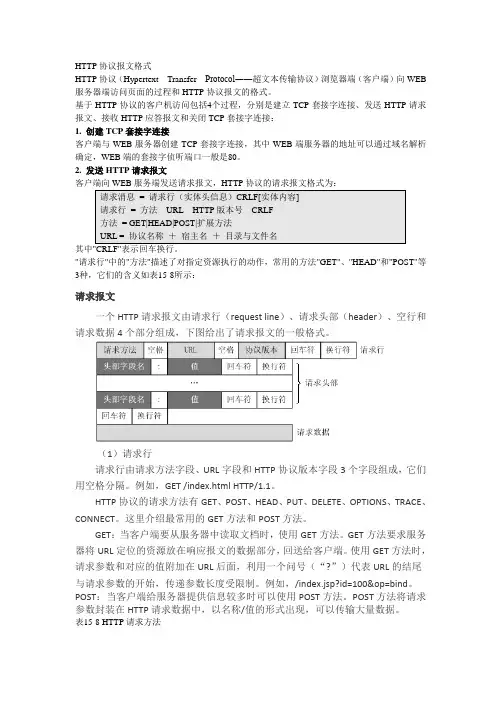
"请求行"中的"方法"描述了对指定资源执行的动作,常用的方法"GET"、"HEAD"和"POST"等3种,它们的含义如表15-8所示:请求报文一个HTTP请求报文由请求行(request line)、请求头部(header)、空行和请求数据4个部分组成,下图给出了请求报文的一般格式。
(1)请求行请求行由请求方法字段、URL字段和HTTP协议版本字段3个字段组成,它们用空格分隔。
例如,GET /index.html HTTP/1.1。
HTTP协议的请求方法有GET、POST、HEAD、PUT、DELETE、OPTIONS、TRACE、CONNECT。
这里介绍最常用的GET方法和POST方法。
GET:当客户端要从服务器中读取文档时,使用GET方法。
GET方法要求服务器将URL定位的资源放在响应报文的数据部分,回送给客户端。
使用GET方法时,请求参数和对应的值附加在URL后面,利用一个问号(“?”)代表URL的结尾与请求参数的开始,传递参数长度受限制。
SIPReasonHeaderSIP Reason HeaderOverviewThe Reason Header field for SIP is included in each of the following messages. (ITU-T Recommendation Q.850) ?BYECANCEL4xx, 5xx, and 6xx messagesUp till software 10.3.3 the IMG had the ability to propagate the Reason Header in each of the above messages from the TDM leg of the call to the SIP leg of the call. The Reason Header would indicate why a SIP request or response was issued. In software 10.5.0 the ability to propagate the Reason Header from the SIP leg of a call to the TDM side of the call was added. The Reason Header Field in each of the SIP messages is used primarily for debugging problems in a circuit. Clients and servers are free to ignore this header field as it has no impact on protocol processing. The Reason Header Field satisfies RFC 3326. The Reason Header field now gives the customer the ability to propagate cause code information from SIP to TDM and TDM to SIP without having to configure SIP-T.Call TracingSupport Personnel can enable Call Tracing on the IMG. Once this is accomplished all Reason Header information will be printed out for the following messages:BYECANCEL4xx, 5xx, and 6xx messagesNote: In case of multiple Reason Headers presented in the incoming SIP message, only the first Reason Header is decoded.Benefits:This feature is useful for debugging purpose, particularly if there is a call failure in SIP to SS7 traffic. Below are Call Flows and their corresponding Call Traces. Note that for reference the Reason Header field is shown in red.Implementation (Message propagates from TDM to SIP)CASE #1:Cause Number 1 (404 message)A call is generated from the SIP side to the IMG. The IMG then converts to an SS7 network and receives the IAM message. The SS7 leg sends a release with cause code of 1 (Unallocated Number). The IMG then would send a SIP 404 message with the cause code in the Reason Header indicating the problem is an Unallocated (unassigned) number. See Call Flow and Call Trace belowCall FlowCall Trace<--- [10.129.39.123, 5060 <- 10.129.39.59, 5060]SIP/2.0 404 Not Found Call processing releasedVia: SIP/2.0/UDP 10.129.39.123:5060;branch=z9hG4bK-d87543-672bb759901c9e2a-1--d87543-; rport;received=10.129.39.1 23Contact:Call-ID: 2b61265d2e589e06ZjIzZDY3ZjU4ODA3NmRhODdmNGI4Y2M0NGRmNTYyMTY.From: "Boston";tag=f818c458To: "508";tag=a94c095b773be1dd6e8d668a785a9c8449dcCSeq: 1 INVITEServer: Cantata-SIP/10.3.2.22 Boston 0Reason: Q.850 ;cause=1 ; text="Unallocated (unassigned) number"Content-Length: 0CASE #2:Cause Number 17 (486 message)A call is generated from the SIP side to the IMG. The IMG then converts to an SS7 network and receives the IAM message. The SS7 leg sends a release with cause code of 17 (User Busy). The IMG then would send a SIP 486 message with the cause code in the Reason Header indicating the problem is User Busy. See Call Flow and Call Trace below Call FlowCall Trace<--- [10.129.39.123, 5060 <- 10.129.39.59, 5060]SIP/2.0 486 Busy Here Call processing releasedVia: SIP/2.0/UDP 10.129.39.123:5060;branch=z9hG4bK-d87543-af44ae69a320e04a-1--d87543-; rport;received=10.129.39.1 23Contact:Call-ID: 1c214262d2299f3cZjIzZDY3ZjU4ODA3NmRhODdmNGI4Y2M0NGRmNTYyMTY.From: "Boston";tag=244d4425To: "508";tag=a94c095b773be1dd6e8d668a785a9c84c527CSeq: 1 INVITEServer: Cantata-SIP/10.3.2.22 Boston 0Reason: Q.850 ;cause=17 ; text="User busy"Content-Length: 0CASE #3Cause Number 16 (BYE message)A call is generated from the SS7 side to the IMG. The IMG then converts to a SIP network and receives the INVITE message. The SIP side then sends a 180 ringing response. The SIP side then sends a 200 OK message and the call gets connected. After a while the phone is hung up and the SS7 leg sends a RELEASE with cause code of 16 (Normal Clearing). The IMG then would send a SIP BYE message with the cause code in the Reason Header indicating the problem is a Normal Clearing. See Call Flow and Call Trace belowCall FlowCall Trace<--- [10.129.39.123, 5060 <- 10.129.39.59, 5060]BYEsip:***********.39.123:5060SIP/2.0Via:SIP/2.0/UDP10.129.39.59:5060;rport;branch=z9hG4bK-3a95-46623-19995-361Call-ID:***********************************.39.59CSeq: 2 BYEMax-Forwards: 70To: ;tag=8262313bFrom: ;tag=95ffcd055e0f78f7d5d397020e89288d2b07User-Agent: Cantata-SIP/10.3.2.22 Boston 0Reason: Q.850 ;cause=16 ; text="Normal call clearing"Content-Length: 0CASE #4:Cause Number 3 (404 message)If the user dials an incorrect number that is not in the route table the IMG will reject the call and send a 404 Not Found to the SIP side.Call FlowCall Trace<--- [10.129.39.123, 5060 <- 10.129.39.59, 5060]SIP/2.0 404 Not Found Call processing releasedVia: SIP/2.0/UDP 10.129.39.123:5060;branch=z9hG4bK-d87543-47486a49a1277175-1--d87543-; rport;received=10.129.39.123Contact:Call-ID: 3355d752f5739754ZjIzZDY3ZjU4ODA3NmRhODdmNGI4Y2M0NGRmNTYyMTY.From: "Boston";tag=2816b75aTo: "999";tag=a94c095b773be1dd6e8d668a785a9c84de15CSeq: 1 INVITEServer: Cantata-SIP/10.3.2.37 Boston 0Reason: Q.850 ;cause=3 ; text="No route to destination"Content-Length: 0CASE #5:Cause Number 1 (404 message)In case the user dials correct number but incoming translation table has wrong number, then IMG would reject the call and send a 404 Not Found to the SIP side.Call FlowCall Trace<--- [10.129.39.123, 5060 <- 10.129.39.59, 5060]SIP/2.0 404 Not Found Call processing releasedVia: SIP/2.0/UDP 10.129.39.123:5060;branch=z9hG4bK-d87543-47486a49a1277175-1--d87543-; rport;received=10.129.39.123Contact:Call-ID: 3355d752f5739754ZjIzZDY3ZjU4ODA3NmRhODdmNGI4Y2M0NGRmNTYyMTY.From: "Boston";tag=2816b75aTo: "999";tag=a94c095b773be1dd6e8d668a785a9c84de15CSeq: 1 INVITEServer: Cantata-SIP/10.3.2.37 Boston 0Reason: Q.850 ;cause=1 ; text="Unallocated (unassigned) number"Content-Length: 0Implementation (Message propagates from SIP to SIP)CASE #1:SIP to SIPIn the case of SIP to SIP traffic, the Reason header field is usually not needed in responses because the status code and the reason phrase already provide sufficient information,according to RFC 3326. However, the Reason Header is included for BYE, 4xx, 5xx, and 6xx. Please note that CANCEL message in the SIP to SIP traffic does not include the Reason header field.Call FlowCall Trace<--- [10.129.39.123, 5060 <- 10.129.39.59, 5060]BYEsip:***********.39.123:5060SIP/2.0Via:SIP/2.0/UDP10.129.39.59:5060;rport;branch=z9hG4bK-2701-1786-19997-394Call-ID:************************************.39.59CSeq: 2 BYEMax-Forwards: 70To: ;tag=d47d7510From: ;tag=95ffcd055e0f78f7d5d397020e89288d708eUser-Agent: Cantata-SIP/10.3.2.37 Boston 0Reason: SIP ;cause=16 ; text="Normal call clearing"Content-Length: 0CASE #2:487 MessageIn the case below, where SIP sends an INVITE message and then sends CANCEL, the IMG sends a 487 Request Terminated in response to the CANCEL message.Call FlowCall Trace<--- [10.129.39.123, 5070 <- 10.129.39.59, 5060]SIP/2.0 487 Request TerminatedVia: SIP/2.0/UDP10.129.39.123:5070;branch=z9hG4bK-675e-1160585843-19988-10-129-39-123;received=10.129.39.123 Contact:Call-ID:*************.39.123From: sipp ;tag=1To: sut ;tag=a94c095b773be1dd6e8d668a785a9c84e50dCSeq: 1 INVITEServer: Cantata-SIP/10.3.2.37 Boston 0Reason: SIP ;cause=487 ; text="Request Terminated"Content-Length: 0Implementation (Message propagates from SIP to TDM)CASE #1:Cause NumberA call is generated from SS7 protocol and sent to the IMG. IMG1 converts from SS7 to SIP. Call is then sent to IMG2 where it converts the SIP messaging back to SS7 and the call goes out of IMG2 using SS7 protocol. The call is then release by hanging phone up or any such normal call release scenario. Note the RELEASE message has the reason header information. Below is Call Flow.Call Trace<--- [10.129.45.107, 5060 <- 10.129.45.104, 5060]BYEsip:*****************.45.107:5060SIP/2.0\r\nVia: SIP/2.0/UDP 10.129.45.104:5060;rport;branch=z9hG4bK-149e-1196263031-19999-118\r\nCall-ID:***************************************.45.104\r\nCSeq: 2 BYE\r\nMax-Forwards: 0\r\nTo: ;tag=a94c095b773be1dd6e8d668a785a9c84089db2cd\r\n From: ;tag=95ffcd055e0f78f7d5d397020e89288d4e3f1b4c\r\nUser-Agent: Cantata-SIP/10.5.0.143 Boston 0\r\nReason: Q.850 ;cause=31 ;text="Normal, unspecified"\r\nContent-Length: 0\r\n\r\n。
HTTP协议的多路复用与头部压缩机制解析HTTP(Hypertext Transfer Protocol)是一种用于传输超文本的应用层协议,旨在实现客户端和服务器之间的通信。
在HTTP协议中,多路复用与头部压缩机制被广泛应用,极大地提高了网络传输效率和用户体验。
本文将对HTTP协议的多路复用与头部压缩机制进行详细解析。
一、多路复用多路复用是指在单个TCP连接上,可以同时发送和接收多个HTTP 请求和响应。
在传统的HTTP/1.1版本中,每个请求都需要建立一次TCP连接,即使是同一域名下的请求也无法共享连接。
这导致了大量的连接建立和断开操作,增加了网络延迟和资源消耗。
为了解决这个问题,HTTP/2引入了多路复用机制。
通过在TCP连接上划分多个流(stream),使得客户端可以在同一个连接上同时发送多个请求,并且服务器可以按照请求顺序返回对应的响应。
这种方式避免了频繁的连接建立和断开,显著提高了网络传输效率。
多路复用的实现原理主要涉及到以下几个关键点:1. 帧(Frame):HTTP/2将每个请求和响应拆分为多个帧,每个帧都有对应的帧标识符。
这样可以保证在一个TCP连接上,多个流之间的帧可以混合发送和接收。
2. 流(Stream):每个帧都属于一个特定的流,每个流都有唯一的标识符,用于标识对应的请求或响应。
通过对流的管理,实现多个请求和响应的并行处理。
3. 流优先级(Stream Priority):HTTP/2通过流优先级机制,允许客户端对请求进行优先级排序。
服务器在处理响应时,会优先处理优先级较高的请求,提高了应用性能。
4. 帧交互(Frame Interleaving):在多路复用中,帧的发送和接收是交互进行的。
当客户端发送一个帧时,服务器可能会立即返回一个帧,不需要等到之前的请求处理完毕。
这种交互方式大大减少了请求和响应的等待时间。
通过多路复用,HTTP/2可以在一个TCP连接上同时处理多个请求和响应,避免了多次连接建立的开销,提高了网络传输效率。
HTTP1.1中CHUNKED编码解析一般HTTP通信时,会使用Content-Length头信息性来通知用户代理(通常意义上是浏览器)服务器发送的文档内容长度,该头信息定义于HTTP1.0协议RFC 1945 10.4章节中。
浏览器接收到此头信息后,接受完Content-Length中定义的长度字节后开始解析页面,但如果服务端有部分数据延迟发送吗,则会出现浏览器白屏,造成比较糟糕的用户体验。
解决方案是在HTTP1.1协议中,RFC 2616中14.41章节中定义的Transfer-Encoding: chunked 的头信息,chunked编码定义在3.6.1中,所有HTTP1.1 应用都支持此使用trunked编码动态的提供body 内容的长度的方式。
进行Chunked编码传输的HTTP数据要在消息头部设置:Transfer-Encoding: chunked表示Content Body将用chunked编码传输内容。
根据定义,浏览器不需要等到内容字节全部下载完成,只要接收到一个chunked块就可解析页面.并且可以下载html中定义的页面内容,包括js,css,image等。
采用chunked编码有两种选择,一种是设定Server的IO buffer长度让Server自动flush buffer中的内容,另一种是手动调用IO中的flush函数。
不同的语言IO中都有flush功能:●php: ob_flush(); flush();●perl: STDOUT->autoflush(1);●java: out.flush();●python: sys.stdout.flush()●ruby: stdout.flush采用HTTP1.1的Transfer-Encoding:chunked,并且把IO的buffer flush下来,以便浏览器更早的下载页面配套资源。
当不能预先确定报文体的长度时,不可能在头中包含Content-Length域来指明报文体长度,此时就需要通过Transfer-Encoding域来确定报文体长度。

翻译自:/rfc/rfc6455.txtInternet Engineering Task Force (IETF) I. Fette Request for Comments: 6455 Google, Inc. Category: Standards Track A. Melnikov ISSN: 2070-1721 Isode Ltd. December 2011WebSocket 协议摘要WebSocket协议使在控制环境下运行不受信任代码的客户端和能够选择与那些代码通信的远程主机之间能够双向通信。
用于这个的安全模型是以origin为基础的安全模型,一般被浏览器使用。
协议包含打开握手,其次是基本消息框架,在TCP之上。
这项技术的目的是为基于浏览器的、需要与服务器双向通信的应用程序提供一种不依赖于打开多个HTTP连接的机制(例如,使用XMLHttpRequest 或<iframe> 和长轮询)。
本备忘录的状态这是一个Internet标准跟踪文件。
这个文档是因特网工程师任务组(IETF)的一个产品。
它代表了IETF社区的共识。
它已接受公众审查,因特网工程指导组(IESG)证明可出版。
关于互联网标准的进一步信息在RFC5741的第2章节。
关于本文档当前状态的信息、勘误表和如何提供反馈,可以在/info/rfc6455找到。
版权声明Copyright (c) 2011 IETF Trust and the persons identified as the document authors. All rights reserved.This document is subject to BCP 78 and the IETF Trust’s Legal Provisions Relating to IETF Documents (/license-info) in effect on the date of publication of this document. Please review these documents carefully, as they describe your rights and restrictions with respect to this document. Code Components extracted from this document must include Simplified BSD License text as described in Section 4.e of the Trust Legal Provisions and are provided without warranty as described in the Simplified BSD License.1.介绍1.1.背景这部分是不规范的。
RFC3550RTP:实时应用程序传输协议摘要本文描述RTP(real-time transport protocol),实时传输协议。
RTP在多点传送(多播)或单点传送(单播)的网络服务上,提供端对端的网络传输功能,适合应用程序传输实时数据,如:音频,视频或者仿真数据。
RTP没有为实时服务提供资源预留的功能,也不能保证QoS(服务质量)。
数据传输功能由一个控制协议(RTCP)来扩展,通过扩展,可以用一种方式对数据传输进行监测控制,该协议(RTCP)可以升级到大型的多点传送(多播)网络,并提供最小限度的控制和鉴别功能。
RTP和RTCP被设计成和下面的传输层和网络层无关。
协议支持RTP标准的转换器和混合器的使用。
本文的大多数内容和旧版的RFC1889相同。
在线路里传输的数据包格式没有改变,唯一的改变是使用协议的规则和控制算法。
为了最小化传输,发送RTCP数据包时超过了设定的速率,而在这时,很多的参与者同时加入了一个会话,在这样的情况下,一个新加入到(用于计算的可升级的)计时器算法中的元素是最大的改变。
目录(Table of Contents)1. 引言(Introduction)1 1 术语(Terminology)2 RTP使用场景(RTP Use Scenarios)2 1 简单多播音频会议( Simple Multicast Audio Conference)2 2 音频和视频会议(Audio and Video Conference)2 3 混频器和转换器(Mixers and Translators)2 4 分层编码(Layered Encodings)3 定义(Definitions)4 字节序,校正和时间格式(Byte Order, Alignment, and Time Format)5 RTP数据传输协议(RTP Data Transfer Protocol)5 1 RTP固定头域(RTP Fixed Header Fields)5 2 多路复用RTP会话(Multiplexing RTP Sessions)5 3 RTP头的配置文件详细变更(Profile-Specific Modifications to the RTP Header)5 3 1 RTP报头扩展(RTP Header Extension)6 RTP控制协议(RTP Control Protocol) -- RTCP6 1 RTCP包格式(RTCP Packet Format)6 2 RTCP传输间隔(RTCP Transmission Interval)6 2 1 维护会话成员数目(Maintaining the number of session members)6 3 RTCP包的发送与接收规则(RTCP Packet Send and Receive Rules)6 3 1 计算RTCP传输间隔(Computing the RTCP Transmission Interval)6 3 2 初始化(Initialization)6 3 3 接收RTP或RTCP(非BYE)包(Receiving an RTP or Non-BYE RTCP Packet)6 3 4 接收RTCP(BYE)包(Receiving an RTCP BYE Packet)6 3 5 SSRC计时失效(Timing Out an SSRC)6 3 6 关于传输计时器的到期(Expiration of Transmission Timer)6 37 传输一个 BYE 包(Transmitting a BYE Packet)6 3 8 更新we_sent(Updating we_sent)6 3 9 分配源描述带宽(Allocation of Source Description Bandwidth)6 4 发送方和接收方报告(Sender and Receiver Reports)6 4 1 SR:发送方报告的RTCP包(SR: Sender report RTCP packet)6 4 2 RR:接收方报告的RTCP包(RR: Receiver Report RTCP Packet)6 4 3 扩展发送方和接收方报告(Extending the Sender and Receiver Reports )6 4 4 分析发送方和接收方报告(Analyzing Sender and Receiver Reports )6 5 SDES:源描述RTCP包(SDES: Source description RTCP packet)6 5 1 CNAME:规范终端标识符的SDES数据项(CNAME: Canonical End-Point Identifier SDES Item)6 5 2 NAME:用户名的SDES数据项(NAME: User name SDES item)6 5 3 EMAIL:电子邮件地址的SDES数据项(EMAIL: Electronic Mail Address SDES Item) 6 5 4 PHONE:电话号码的SDES数据项(PHONE: Phone Number SDES Item)6 5 5 LOC:地理用户地址的SDES数据项(LOC: Geographic User Location SDES Item)6 5 6 TOOL:应用程序或工具名字的SDES数据项(TOOL: Application or Tool Name SDES Item) 6 57 NOTE:通知/状态的SDES数据项(NOTE: Notice/Status SDES Item)6 5 8 PRIV:私有扩展的SDES数据项(PRIV: Private Extensions SDES Item)6 6 BYE:Goodbye RTCP包(BYE: Goodbye RTCP packet)6 7 APP:定义应用程序的RTCP包(APP: Application-Defined RTCP Packet)7 RTP转换器和混频器(RTP Translators and Mixers)7 1 概述(General Description )7 2 在转换器中的RTCP数据处理(RTCP Processing in Translators)7 3 在混频器中的RTCP数据处理(RTCP Processing in Mixers )7 4 级联混频器(Cascaded Mixers)8 SSRC标识符的分配和使用(SSRC Identifier Allocation and Use)8 1 冲突概率(Probability of Collision )8 2 冲突解决和循环检测(Collision Resolution and Loop Detection)8 3 在分层编码中使用(Use with Layered Encodings)9 安全(Security )9 1 机密性(Confidentiality)9 2 身份验证和消息完整性(Authentication and Message Integrity)10 拥塞控制(Congestion Control)11 网络和传输协议之上的RTP(RTP over Network and Transport Protocols)12 协议常量摘要(Summary of Protocol Constants)12 1 RTCP 包类型(RTCP Packet Types)12 2 SDES 类型(SDES Types)13 RTP概况和负载格式详细说明(RTP Profiles and Payload Format Specifications)14 安全考虑(Security Considerations)15 IANA考虑(IANA Considerations)16 知识产权声明(Intellectual Property Rights Statement)17 鸣谢(Acknowledgments)附录 A 算法(Algorithms)附录 A 1 RTP数据头有效性检查(RTP Data Header Validity Checks )附录 A 2 RTCP数据头有效性检查(RTCP Header Validity Checks)附录 A 3 确定RTP包预期数目和丢失数目(Determining Number of Packets Expected and Lost)附录 A 4 生成SDES RTCP包(Generating RTCP SDES Packets)附录 A 5 解析RTCP SDES包(Parsing RTCP SDES Packets)附录 A 6 生成32位随机标识符(Generating a Random 32-bit Identifier附录 A 7 计算RTCP传输间隔(Computing the RTCP Transmission Interval)附录 A 8 估测两次到达间隔的抖动(Estimating the Interarrival Jitter)附录 B 与RFC1889不同之外(Changes from RFC 1889)参考书目(References)标准化引用(Normative References )资料性引用(Informative References)作者地址完整的版权声明1.绪论本文详细的介绍实时传输协议RTP,RTP提供带有实时特性的端对端数据传输服务,传输的数据如:交互式的音频和视频。
Network Working Group P.Deutsch Request for Comments:1952Aladdin Enterprises Category:Informational May1996 GZIPfile format specification version4.3Status of This MemoThis memo provides information for the Internet community.This memo does not specify an Internet stan-dard of any kind.Distribution of this memo is unlimited.IESG Note:The IESG takes no position on the validity of any Intellectual Property Rights statements contained in this document.NoticesCopyright c1996L.Peter DeutschPermission is granted to copy and distribute this document for any purpose and without charge,including translations into other languages and incorporation into compilations,provided that the copyright notice and this notice are preserved,and that any substantive changes or deletions from the original are clearly marked.A pointer to the latest version of this and related documentation in HTML format can be found at the URL ftp:///graphics/png/documents/zlib/zdoc-index.html.AbstractThis specification defines a lossless compressed data format that is compatible with the widely used GZIP utility.The format includes a cyclic redundancy check value for detecting data corruption.The format presently uses the DEFLATE method of compression but can be easily extended to use other compression methods.The format can be implemented readily in a manner not covered by patents.Contents1Introduction (2)1.1Purpose (2)1.2Intended audience (2)1.3Scope (2)1.4Compliance (3)1.5Definitions of terms and conventions used (3)1.6Changes from previous versions (3)2Detailed specification (3)2.1Overall conventions (3)2.2File format (4)2.3Member format (4)2.3.1Member header and trailer (5)Extrafield (7)Compliance (8)3References (8)4Security Considerations (8)5Acknowledgements (9)6Author’s Address (9)7Appendix:Jean-Loup Gailly’s gzip utility (9)8Appendix:Sample CRC Code (10)1Introduction1.1PurposeThe purpose of this specification is to define a lossless compressed data format that:Is independent of CPU type,operating system,file system,and character set,and hence can be used for interchange;Can compress or decompress a data stream(as opposed to a randomly accessiblefile)to produce an-other data stream,using only an a priori bounded amount of intermediate storage,and hence can be used in data communications or similar structures such as Unixfilters;Compresses data with efficiency comparable to the best currently available general-purpose compres-sion methods,and in particular considerably better than the“compress”program;Can be implemented readily in a manner not covered by patents,and hence can be practiced freely;Is compatible with thefile format produced by the current widely used gzip utility,in that conforming decompressors will be able to read data produced by the existing gzip compressor.The data format defined by this specification does not attempt to:Provide random access to compressed data;Compress specialized data(e.g.,raster graphics)as well as the best currently available specialized al-gorithms.1.2Intended audienceThis specification is intended for use by implementors of software to compress data into gzip format and/or decompress data from gzip format.The text of the specification assumes a basic background in programming at the level of bits and other prim-itive data representations.1.3ScopeThe specification specifies a compression method and afile format(the latter assuming only that afile can store a sequence of arbitrary bytes).It does not specify any particular interface to afile system or anything about character sets or encodings(except forfile names and comments,which are optional).1.4ComplianceUnless otherwise indicated below,a compliant decompressor must be able to accept and decompress anyfile that conforms to all the specifications presented here;a compliant compressor must producefiles that conform to all the specifications presented here.The material in the appendices is not part of the specification per se and is not relevant to compliance.1.5Definitions of terms and conventions usedbyte:8bits stored or transmitted as a unit(same as an octet).(For this specification,a byte is exactly8bits, even on machines which store a character on a number of bits different from8.)See below for the numbering of bits within a byte.1.6Changes from previous versionsThere have been no technical changes to the gzip format since version4.1of this specification.In version 4.2,some terminology was changed,and the sample CRC code was rewritten for clarity and to eliminate the requirement for the caller to do pre-and post-conditioning.Version4.3is a conversion of the specification to RFC style.2Detailed specification2.1Overall conventionsIn the diagrams below,a box like this:+---+||<--the vertical bars might be missing+---+represents one byte;a box like this:+==============+||+==============+represents a variable number of bytes.Bytes stored within a computer do not have a“bit order”,since they are always treated as a unit.However, a byte considered as an integer between0and255does have a most-and least-significant bit,and since we write numbers with the most-significant digit on the left,we also write bytes with the most-significant bit on the left.In the diagrams below,we number the bits of a byte so that bit0is the least-significant bit,i.e.,the bits are numbered:+--------+|76543210|+--------+This document does not address the issue of the order in which bits of a byte are transmitted on a bit-sequential medium,since the data format described here is byte-rather than bit-oriented.Within a computer,a number may occupy multiple bytes.All multi-byte numbers in the format described here are stored with the least-significant bytefirst(at the lower memory address).For example,the decimal number520is stored as:01+--------+--------+|00001000|00000010|+--------+--------+ˆˆ|||+more significant byte=2x256+less significant byte=82.2File formatA gzipfile consists of a series of“members”(compressed data sets).The format of each member is spec-ified in the following section.The members simply appear one after another in thefile,with no additional information before,between,or after them.2.3Member formatEach member has the following structure:+---+---+---+---+---+---+---+---+---+---+|ID1|ID2|CM|FLG|MTIME|XFL|OS|(more-->)+---+---+---+---+---+---+---+---+---+---+(if FLG.FEXTRA set)+---+---+=================================+|XLEN|...XLEN bytes of"extra field"...|(more-->)+---+---+=================================+(if FLG.FNAME set)+=========================================+|...original file name,zero-terminated...|(more-->)+=========================================+(if FLG.FCOMMENT set)+===================================+|...file comment,zero-terminated...|(more-->)+===================================+(if FLG.FHCRC set)+---+---+|CRC16|+---+---++=======================+|pressed blocks...|(more-->)+=======================+01234567+---+---+---+---+---+---+---+---+|CRC32|ISIZE|+---+---+---+---+---+---+---+---+2.3.1Member header and trailerID1(IDentification1)ID2(IDentification2)These have thefixed values ID1=31(0x1f,\037),ID2=139(0x8b,\213),to identify thefile as being in gzip format.CM(Compression Method)This identifies the compression method used in thefile.CM=0-7are reserved.CM=8denotes the “deflate”compression method,which is the one customarily used by gzip and which is documented elsewhere.FLG(FLaGs)Thisflag byte is divided into individual bits as follows:bit0FTEXTbit1FHCRCbit2FEXTRAbit3FNAMEbit4FCOMMENTbit5reservedbit6reservedbit7reservedIf FTEXT is set,thefile is probably ASCII text.This is an optional indication,which the compressor may set by checking a small amount of the input data to see whether any non-ASCII characters are present.In case of doubt,FTEXT is cleared,indicating binary data.For systems which have different file formats for ascii text and binary data,the decompressor can use FTEXT to choose the appropriate format.We deliberately do not specify the algorithm used to set this bit,since a compressor always has the option of leaving it cleared and a decompressor always has the option of ignoring it and letting some other program handle issues of data conversion.If FHCRC is set,a CRC16for the gzip header is present,immediately before the compressed data.The CRC16consists of the two least significant bytes of the CRC32for all bytes of the gzip header up to and not including the CRC16.[The FHCRC bit was never set by versions of gzip up to1.2.4,even though it was documented with a different meaning in gzip1.2.4.]If FEXTRA is set,optional extrafields are present,as described in a following section.If FNAME is set,an originalfile name is present,terminated by a zero byte.The name must consist of ISO8859-1(LATIN-1)characters;on operating systems using EBCDIC or any other character set for file names,the name must be translated to the ISO LATIN-1character set.This is the original name of thefile being compressed,with any directory components removed,and,if thefile being compressed is on afile system with case insensitive names,forced to lower case.There is no originalfile name if the data was compressed from a source other than a namedfile;for example,if the source was stdin on a Unix system,there is nofile name.If FCOMMENT is set,a zero-terminatedfile comment is present.This comment is not interpreted;it is only intended for human consumption.The comment must consist of ISO8859-1(LATIN-1)char-acters.Line breaks should be denoted by a single line feed character(10decimal).Reserved FLG bits must be zero.MTIME(Modification TIME)This gives the most recent modification time of the originalfile being compressed.The time is in Unix format,i.e.,seconds since00:00:00GMT,Jan.1,1970.(Note that this may cause problems for MS-DOS and other systems that use local rather than Universal time.)If the compressed data did not come from afile,MTIME is set to the time at which compression started.MTIME=0means no time stamp is available.XFL(eXtra FLags)Theseflags are available for use by specific compression methods.The“deflate”method(CM=8) sets theseflags as follows:XFL=2-compressor used maximum compression,slowest algorithmXFL=4-compressor used fastest algorithmOS(Operating System)This identifies the type offile system on which compression took place.This may be useful in deter-mining end-of-line convention for textfiles.The currently defined values are as follows: 0-FAT filesystem(MS-DOS,OS/2,NT/Win32)1-Amiga2-VMS(or OpenVMS)3-Unix4-VM/CMS5-Atari TOS6-HPFS filesystem(OS/2,NT)7-Macintosh8-Z-System9-CP/M10-TOPS-2011-NTFS filesystem(NT)12-QDOS13-Acorn RISCOS255-unknownXLEN(eXtra LENgth)If FLG.FEXTRA is set,this gives the length of the optional extrafield.See below for details.CRC32(CRC-32)This contains a Cyclic Redundancy Check value of the uncompressed data computed according to CRC-32algorithm used in the ISO3309standard and in section8.1.1.6.2of ITU-T recommendationV.42.(See http://www.iso.ch for ordering ISO documents.See gopher://info.itu.ch for an online ver-sion of ITU-T V.42.)ISIZE(Input SIZE)This contains the size of the original(uncompressed)input data modulo2ˆ32.Extrafield If the FLG.FEXTRA bit is set,an“extrafield”is present in the header,with total length XLEN bytes.It consists of a series of subfields,each of the form:+---+---+---+---+==================================+|SI1|SI2|LEN|...LEN bytes of subfield data...|+---+---+---+---+==================================+SI1and SI2provide a subfield ID,typically two ASCII letters with some mnemonic value.Jean-Loup Gailly gzip@ is maintaining a registry of subfield IDs;please send him any subfield ID you wish to use.Subfield IDs with SI2=0are reserved for future use.The following IDs are currently defined: SI1SI2Data------------------------0x41(’A’)0x70(’P’)Apollo file type informationLEN gives the length of the subfield data,excluding the4initial bytes.Compliance A compliant compressor must producefiles with correct ID1,ID2,CM,CRC32,and ISIZE, but may set all the otherfields in thefixed-length part of the header to default values(255for OS,0for all others).The compressor must set all reserved bits to zero.A compliant decompressor must check ID1,ID2,and CM,and provide an error indication if any of these have incorrect values.It must examine FEXTRA/XLEN,FNAME,FCOMMENT and FHCRC at least so it can skip over the optionalfields if they are present.It need not examine any other part of the header or trailer;in particular,a decompressor may ignore FTEXT and OS and always produce binary output,and still be compliant.A compliant decompressor must give an error indication if any reserved bit is non-zero, since such a bit could indicate the presence of a newfield that would cause subsequent data to be interpreted incorrectly.3References[1]“Information Processing-8-bit single-byte coded graphic character sets-Part1:Latin alphabet No.1”(ISO8859-1:1987).The ISO8859-1(Latin-1)character set is a superset of7-bit ASCII.Files defining this character set are available as iso[3]ITU-T recommendation V.42[4]Deutsch,L.P.,“DEFLATE Compressed Data Format Specification”,available in ftp:///pub/ archiving/zip/doc/[5]Gailly,J.-L.,GZIP documentation,available as gzip-*.tar in ftp:///pub/gnu/[6]Sarwate,D.V.,“Computation of Cyclic Redundancy Checks via Table Look-Up”,Communications of the ACM,31(8),pp.1008-1013.[7]Schwaderer,W.D.,“CRC Calculation”,April85PC Tech Journal,pp.118-133.[8]ftp://.au/pub/rocksoft/papers/crcJean-Loup Gailly<gzip@>andMark Adler<madler@>Editorial comments on this specification can be sent by email to:L.Peter Deutsch<ghost@>andGlenn Randers-Pehrson<randeg@>7Appendix:Jean-Loup Gailly’s gzip utilityThe most widely used implementation of gzip compression,and the original documentation on which this specification is based,were created by Jean-Loup Gailly gzip@.Since this implementa-tion is a de facto standard,we mention some more of its features here.Again,the material in this section is not part of the specification per se,and implementations need not follow it to be compliant.When compressing or decompressing afile,gzip preserves the protection,ownership,and modification time attributes on the localfile system,since there is no provision for representing protection attributes in the gzipfile format itself.Since thefile format includes a modification time,the gzip decompressor provides a command line switch that assigns the modification time from thefile,rather than the local modification time of the compressed input,to the decompressed output.8Appendix:Sample CRC CodeThe following sample code represents a practical implementation of the CRC(Cyclic Redundancy Check). (See also ISO3309and ITU-T V.42for a formal specification.)The sample code is in the ANSI C programming language.Non C users mayfind it easier to read with these hints:&Bitwise AND operator.ˆBitwise exclusive-OR operator.>>Bitwise right shift operator.When applied to anunsigned quantity,as here,right shift inserts zerobit(s)at the left.!Logical NOT operator.++"n++"increments the variable n.0xNNN0x introduces a hexadecimal(base16)constant.Suffix L indicates a long value(at least32bits)./*Table of CRCs of all8-bit messages.*/unsigned long crctable/*Make the table for a fast CRC.*/void make table(void)unsigned long c;int n,k;for(n=0;n<256;n++)c=(unsigned long)n;for(k=0;k<8;k++)if(c&1)c=0xedb88320Lˆ(c>>1);elsec=c>>1;crctablebuffer(buffer,length)!=EOF)crc=updatecrc)error();*/unsigned long updatetablecrctable[(cˆbuf[n])&0xff]ˆ(c>>8);return cˆ0xffffffffL;Deutsch Informational[Page11]/*Return the CRC of the bytes buf[0..len-1].*/ unsigned long crc(unsigned char*buf,int len) return update。
电子邮件也许是一个Internet上的流行最广泛的应用。
也是我们现在的大多数网络办公流程的基础。
各种邮件服务器很多,但都大都遵循以1982年出版的RFC822--《ARPA网络文本信息格式标准(STANDARD FOR THE FORMAT OF ARPA INTERNET TEXT MESSAGES)》为基础的一系列邮件格式的规定。
RFC(The Requests for Comments)是用来规定互联网工作标准的文档。
我们使用的时候并没有注意到这些协议在我们的邮件通信过程中默默的发挥着的作用,这丝毫也不能减低这些作用的重要性。
邮件内部还有很多不为人知的秘密。
在RFC822中规定一封信包括一个必须的多个头部域(header fields)和一个可选的体部(body)组成。
从一封信头开始至第一个空行都是头部。
头部定义了一个邮件的各项基本要素,路由信息等内容。
在Outlook Express中选定一封信看它的属性。
在详细资料选项卡中显示的就是这封邮件的头部内容。
也可以选定一封信,另存为一个.eml文件。
由于文件是一个纯文本文件,用一般的编辑器打开就可以看到邮件的内容。
头部有各个头部域组成,每一个头部域都包括域名(field-name)和域体(field-body),它们之间以":"分隔。
每一个头部域都可以看作由ASCII码字符组成的独立的文本。
常见的头部域包括:"Return-Path", "Received", "Date", "From", "Subject", "Sender","To", "cc","MIME-Version"等。
各头部域之间没有规定顺序。
就像各个域的名字一样。
他们表示的具体意义也不同。
中文RFC文档阅读2501-3000RFC2508 低速串行链路下IP/UDP/RTP数据包头的压缩RFC2511 Internet X.509认证请求消息格式RFC2516 在以太网上传输PPP的方法(PPPoE)RFC2526 IPv6保留的子网任意传送地址RFC2541 DNS 安全操作考虑RFC2547 BGP/MPLS VPNsRFC2554 SMTP服务认证扩展RFC2560 x.509因特网公钥基础设施在线证书状态协议——OCSPRFC2570 标准互联网络管理框架第三版介绍RFC2577 FTP 安全考虑RFC2581 TCP拥塞控制RFC2582 TCP的快速恢复算法NewReno修正RFC2585 Internet X.509 公共键底部结构操作协议: FTP和HTTPRFC2597 确定的面向PHB组RFC2598 面向加速PHBRFC2618 RADIUS 身份验证客户端管理系统库(MIB)RFC2629 用XML 写I-Ds 和RFC文档RFC2633 S/多用途网际邮件扩充协议(MIME) 版本3 信息说明书RFC2644 更改直接广播在路由器上的缺省值RFC2669 DOCSIS 电缆设备管理系统库(MIB) 电缆设备管理信息基础用于DOCSIS 适应性电缆调制解调器和电缆调制解调器中断系统RFC2670 音频频率(RF)界面管理信息基础用于MCNS/DOCSIS适应性RF界面RFC2685 虚拟专用网标志符RFC2702 基于MPLS的流量工程要求RFC2706 ECML v1:电子商务字段名RFC2713 LDAP(轻型目录存取协议)目录中JAVATM对象的表征模式RFC2714 LDAP(轻型目录存取协议)目录中的CORBA对象参考方案RFC2731 Dublin核心元数据在HTML上的编码RFC2732 文本IPv6地址在URL上的格式RFC2733 RTP有效载荷格式用于普通正向错误更正RFC2736 RTP有效载荷格式说明书作者的指导方针RFC2754 RPS IANA的发布RFC2756 超文本缓存协议(HTCP/0.0)RFC2764 IP VPN的框架体系RFC2773 使用KEA和SKIPJACK加密RFC2774 HTTP 扩展框架RFC2781 UTF-16,ISO 10646的一种编码RFC2784 通用路由封装(GRE)RFC2788 网络服务监视MIBRFC2793 用于文本交谈的RTP负载RFC2796 BGP路由映象RFC2809 通过RADIUS的L2TP强制通道的执行RFC2810 Internet 延迟交谈:体系结构RFC2811 Internet延迟交谈:通道管理RFC2813 Internet 延迟交谈:服务器协议RFC2817 在HTTP/1.1中升级到TLSRFC2818 TLS之上的HTTPRFC2824 呼叫过程语言框架和要求RFC2825 复杂网络:I18N的发布,域名,和其它Internet协议RFC2829 LDAP的身份验证方法RFC2830 轻量级目录访问协议(v3): 传输层安全扩展RFC2833 用于DTMF数字信号、电话音和电话信号的RTP负载格式RFC2854 text/html 媒体类型RFC2855 IEEE 1394的DHCPRFC2861 TCP 拥塞窗口检验RFC2862 用于实时指针的RTP负载格式RFC2866 RADIUS(远程用户拨号认证系统)记帐协议RFC2867 RADIUS 账目管理修改用于通道协议支持RFC2868 RADIUS 属性用于协议支持RFC2869 RADIUS 扩展RFC2871 一个IP电话路由框架RFC2873 在Ipv4优先域中的TCP过程RFC2874 支持IPv6地址集合和重编号的DNS 扩展RFC2882 网络访问服务要求: 扩展范围实践RFC2887 可靠的多点传送设计空间用于大的数据传送RFC2889 基准方法论用于局域网交换设备RFC2890 GRE中Key和SequenceNumber扩展RFC2893 IPv6 主机和软件路由器转换机制RFC2898 PKCS #5: 基于密码的密码系统说明书版本 2.0. BRFC2906 AAA 授权要求RFC2914 拥塞控制原理RFC2917 核心MPLS IP VPN 体系结构RFC2918 BGP-4(边界网关协议)的路由刷新功能RFC2920 SMTP 针对命令流水线的服务扩展RFC2923 TCP的路径MTU发现问题RFC2932 IPv4 多点传送路由管理系统库(MIB)RFC2935 Internet开放贸易协议(IOTP)HTTP 补充RFC2939 新DHCP选项和信息类型的定义步骤和IANA指导方针RFC2945 SRP身份验证和键交换系统RFC2946 Telnet 数据加密选项RFC2947 Telnet加密:DES3 64位密码回馈RFC2948 Telnet加密:DES3 64位输出回馈RFC2949 Telnet加密:CAST-128 64比特输出回馈RFC2950 Telnet加密:CAST-128 64比特密码回馈RFC2951 使用KEA和SKIPJACK进行TELNET身份验证RFC2952 Telnet加密:DES 64位密码回馈RFC2953 Telnet加密:DES 64比特输出回馈RFC2957 The 应用/whoispp-请求目录-类型RFC2958 The 应用/whoispp-回答目录-类型RFC2959 实时传输协议管理信息库RFC2964 超文本传输协议(HTTP)状态管理的应用RFC2971 Internet信息访问协议(IMAP4)的标识符扩展RFC2976 SIP信息方法RFC2983 有区别的协议和通道RFC2984 CAST-128密码算法在CMS中的使用RFC2987 字符集注册和语言媒体特征标签RFC2988 计算TCP重传时间的定时器RFC2991 多路径分发在Unicast上和多点传送下一路程段选择RFC2992 等值多-路径算法的分析RFC2994 MISTY1加密算法的描述。
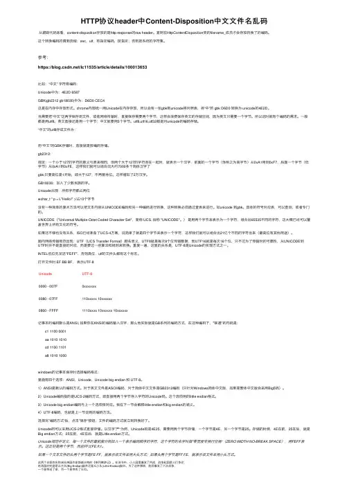
HTTP协议header中Content-Disposition中⽂⽂件名乱码从跟踪代码来看,content-disposition存放的是http response的raw header。
直到在HttpContentDisposition类的filename_成员才会存放转换了的编码。
这个转换编码的猜测流程:asc,utf,有指定编码,按指定;否则按系统的字符集。
参考:https:///lc11535/article/details/100013653⽐如:“中⽂” 字符得编码:Unicode中为:4E2D 6587GBK(gb2312 gb18030)中为:D6D0 CEC4这是在内存中存放形式。
chrome内部统⼀⽤Unicode在内存存放,所以会有⼀张gbk到unicode得对照表,将“中”的 gbk D6D0 转换为 unicode的4E2D。
当需要把“中⽂”这两字保存到⽂件,或者⽹络传输时,直接保存需要两个字节,这样会浪费保存英⽂的存储空间,因为英⽂只需要⼀个字节。
所以这时就有个编码的需求。
⼀般都是⽤utf8。
英⽂直接还是⽤⼀个字节;中⽂就要⽤3个字节。
utf8,utf16,utf32都是对unicode的编码存储。
“中⽂”的utf8存成⽂件为:⽽“中⽂”的GBK存储时,直接就是按编码存储。
gb2312:规定:⼀个⼩于127的字符的意义与原来相同,但两个⼤于127的字符连在⼀起时,就表⽰⼀个汉字,前⾯的⼀个字节(他称之为⾼字节)从0xA1⽤到0xF7,后⾯⼀个字节(低字节)从0xA1到0xFE,这样我们就可以组合出⼤约7000多个简体汉字了gbk:只要⾼位是1开始,即⼤于127;不再管地位。
这样增加了2万汉字。
GB18030:加⼊了少数民族的字。
Unicode出现:所有字符都占两位wchar_t * p = L"Hello!" ;//占10个字节没有⼀种简单的算术⽅法可以把⽂本内容从UNICODE编码和另⼀种编码进⾏转换,这种转换必须通过查表来进⾏。

VoLTE/SRVCC原理与性能分析2015-11目录无线特性基本原理功能特性网络结构信令流程案例分析VoIP 协议层RTP 是用于传送实时话音和视频数据的IP 协议,负责实时数据的传输。
RTCP 是RTP 控制协议,负责对RTP 的通信和会话进行控制和管理,如流量控制、拥塞控制、会话管理等,以便于发送方进行错误纠正。
RTPUDPIP RTCP 话音12.2KbpsSIP IP RTP RTCP 用户面控制面VoIP 头压缩IP 包头UDP 包头RRP 包头RTP 载荷20字节8字节12字节20~160字节包头压缩后:RRP包头RTP 载荷3~5字节20~160字节IP/UDP/RTP 包头RTPRTP•RTP 典型的负荷长度为20字节到160字节,而RTP 的头部一般为40到60字节。
•可以通过RoHC(Robust Header Compression ,RFC3095)算法对RTP/UDP/IP 包头进行压缩。
•VoIP AMR 话音包头被压缩后的长度为1~4字节。
VOIP AMR 参数及调度特性VoIP 包, AMR12.2Kbps 时长度为352比特SID 包,,包长度为120比特交谈状态发包间隔为20ms 静默状态发包间隔为160ms 状态半持续性调度资源释放半持续性调度资源激活动态调度半持续性调度集中式虚拟资源块分布式虚拟资源块SID 包VoIP 包大的IP 包静默态谈话态VoIP无线特性VoIP基本特性:–严格的分组时延要求–突发性低比特率话务VoIP面临的挑战:–延迟和抖动控制。
–移动性。
–发射功率和覆盖优化•解决和优化方案:–多用户共享–包头压缩技术–动态调度方式–半静态调度方式–针对VoIP的切换方式VoLTE/无线技术关键点头压缩功能•对数据包包头进行压缩:不采用ROHC头压缩,应用层RTP开销占12Byte,UDP头开销占8Byte,IP层的IP头开销占20Byte(IPv4);采用ROHC头压缩后,ROHC头压缩开销占6Byte左右,每个数据包可以节省包头开销34Byte。
TCP学习笔记-RFC1122(⼆)学习TCP/UDP过程中,有⼀些基本概念需要搞清楚。
其中如下定义请注意:SegmentA segment is the unit of end-to-end transmission in the TCP protocol. A segment consists of a TCP header followed by application data. A segment is transmitted by encapsulation inside an IP datagram.MessageIn this description of the lower-layer protocols, a message is the unit of transmission in a transport layer protocol. In particular, a TCP segment is a message. A message consists of a transport protocol header followed by application protocol data. To be transmitted end-to end through the Internet, a message must be encapsulated inside a datagram.IP DatagramAn IP datagram is the unit of end-to-end transmission in the IP protocol. An IP datagram consists of an IP header followed by transport layer data, i.e., of an IP header followed by a message. In the description of the internet layer (Section 3), the unqualified term "datagram" should be understood to refer to an IP datagram.PacketA packet is the unit of data passed across the interface between the internet layer and the link layer. It includes an IP header and data. A packet may be a complete IP datagram or a fragment of an IP datagram.FrameA frame is the unit of transmission in a link layer protocol, and consists of a link-layer header followed by a packet.。
Network Working Group J. Palme Request for Comments: 2076 Stockholm University/KTH Category: Informational February 1997Common Internet Message HeadersStatus of this MemoThis memo provides information for the Internet community. This memo does not specify an Internet standard of any kind. Distribution of this memo is unlimited.AbstractThis memo contains a table of commonly occurring headers in headings of e-mail messages. The document compiles information from other RFCs such as RFC 822, RFC 1036, RFC 1123, RFC 1327, RFC 1496, RFC 1521,RFC 1766, RFC 1806, RFC 1864 and RFC 1911. A few commonly occurring headers which are not defined in RFCs are also included. For eachheader, the memo gives a short description and a reference to the RFC in which the header is defined.Table of contents1. Introduction (2)2. Use of gatewaying headers (3)3. Table of headers (3)3.1 Phrases used in the tables (3)3.2 Trace information (5)3.3 Format and control information (5)3.4 Sender and recipient indication (6)3.5 Response control (9)3.6 Message identification and referral headers (11)3.7 Other textual headers (12)3.8 Headers containing dates and times (13)3.9 Quality information (13)3.10 Language information (14)3.11 Size information (14)3.12 Conversion control (15)3.13 Encoding information (15)3.14 Resent-headers (16)3.15 Security and reliability (16)3.16 Miscellaneous (16)4. Acknowledgments (18)Palme Informational [Page 1] RFC 2076 Internet Message Headers February 19975. References (18)6. Author's Address (20)Appendix A:Headers sorted by Internet RFC document in which they appear. 21Appendix B:Alphabetical index (25)1. IntroductionMany different Internet standards and RFCs define headers which may occur on Internet Mail Messages and Usenet News Articles. Theintention of this document is to list all such headers in onedocument as an aid to people developing message systems or interested in Internet Mail standards.The document contains all headers which the author has found in the following Internet standards: , RFC 822 [2], RFC 1036 [3], RFC 1123 [5], RFC 1327 [7], RFC 1496 [8], RFC 1521 [11], RFC 1766 [12], RFC1806 [14], RFC 1864[17] and RFC 1911[20]. Note in particular thatheading attributes defined in PEM (RFC 1421-1424) and MOSS (RFC 1848 [16]) are not included. PEM and MOSS headers only appear inside the body of a message, and thus are not headers in the RFC 822 sense.3.9 Priority3.2 ReceivedRecipient, see To, cc, bcc, Alternate-Recipient, Disclose-Recipient3.6 References3.8 Reply-By3.4 Reply-To, see also In-Reply-To, References3.14 Resent-Return see also Content-Return3.2 Return-PathPalme Informational [Page 26] RFC 2076 Internet Message Headers February 19973.5 Return-Receipt-To3.6 See-Also3.4 Sender3.9 Sensitivity3.16 Status3.7 Subject3.7 Summary3.6 Supersedes3.4 Telefax3.4 ToTransfer-Encoding see Content-Transfer-EncodingType see Content-Type, Message-Type, Original-Encoded-Information-TypesVersion, see MIME-Version, X-Mailer3.4 X400-Content-Return3.4 X-Mailer see also Mail-System-Version3.4 X-Newsreader3.15 XrefPalme Informational [Page 27]。
目录LTE L2整体协议介绍GTPU协议层PDCP协议层RLC协议层3GPP LTE/EPS架构E-UTRAN架构用户面协议栈UE -P-GWServing GW PDN GWaeNodeB UE控制面协议栈UE -MMELTE-UueNodeB MME UEL2 协议栈User-plane protocol stackLTE 信道映射L2数据处理目录LTE L2整体协议介绍GTPU协议层PDCP协议层RLC协议层GTPU协议层在LTE中的主要功能F为地面协议,严格来说,不属于L2。
GTP-U目前用于X2/S1/S5接口用户面数据传输F GTP-U承载在UDP之上,Port为2125F隧道协议,在两个端点间建立专用隧道,传输用户数据F通过扩展头在切换时传输AM模式下未确定的PDCP PDU SN序号F GTP-U V1.0 新增加了End Marker MessageEnd Marker消息指示了在GTP隧道中传输的数据在发送端已经全部被发送完毕。
.BitsOctets 876543211Version PT (*)ES PN2Message Type 3Length (1st Octet)4Length (2nd Octet)5Tunnel Endpoint Identifier (1st Octet)6Tunnel Endpoint Identifier (2nd Octet)7Tunnel Endpoint Identifier (3rd Octet)8Tunnel Endpoint Identifier (4th Octet)9Sequence Number (1st Octet)1) 4)10Sequence Number (2nd Octet)1)4)11N-PDU Number 2) 4)12Next Extension Header Type 3) 4)GTPU 协议头(V1)LTE L2整体协议介绍GTPU协议层PDCP协议层RLC协议层PDCP协议层主要功能F用户面数据传输F控制面数据传输F加密ØPDCP控制PDU不加密ØSRB PDU的加密范围包括数据和MAC-IØDRB PDU的加密范围只包括数据F完整性保护(控制面)F头压缩(用户面),支持RFC 3095/3843/4995/4996F映射到AM RLC的RB的PDCP序列号维护、切换时的重复检测F切换时的按序递交F基于时间的数据丢弃PDCP 结构图Radio BearersUE/E-UTRANPDCPRLCPDCP实体功能…ROHCProfile Identifier Usage:Reference0x0000No compression RFC 49950x0001RTP/UDP/IP RFC 30950x0002UDP/IP RFC 30950x0003ESP/IP RFC 30950x0004IP RFC 38430x0006TCP/IP RFC 49960x0101RTP/UDP/IP RFC 49950x0102UDP/IP RFC 49950x0103ESP/IP RFC 49950x0104IP RFC 4995控制面数据示意Oct 1Oct 2Oct N Oct N-1Oct N-2Oct N-3用户面数据示意(映射在AM/UM RLC时)用户面数据示意(映射在UM RLC时)控制PDU –ROHC反馈控制PDU –PDCP状态报告映射在RLC AM上的DRB的切换F切换发生后根据RRC配置,UE发送PDCP下行状态报告(Target eNB可选择发送上行状态报告)F UE负责下行数据的按序递交和重复检测F高层指示发生HO后,UE PDCP重发未得到确认的上行数据。
标准参考文档链路层协议PPP(Point-to-Point Protocol):RFC 1332: The PPP Internet Protocol Control Protocol (IPCP)RFC 1334: PPP Authentication ProtocolsRFC 1552: The PPP Internetworking Packet Exchange Control Protocol (IPXCP) RFC 1570: PPP LCP Extensions(实现了其中的callback选项)RFC 1661: The Point-to-Point Protocol (PPP)RFC 1877: PPP Internet Protocol Control Protocol Extensions for Name Server AddressesRFC 1990: The PPP Multilink Protocol (MP)RFC 1994: PPP Challenge Handshake Authentication Protocol (CHAP)RFC 2509: IP Header Compression over PPPRFC 1962: The PPP Compression Control Protocol (CCP)RFC 1974: PPP Stac LZS Compression ProtocoldX25、LAPB(Link Access Protocol Balanced):RFC1613:Cisco Systems X.25 over TCP(XOT)RFC1598:PPP in X.25RFC1461:SNMP MIB extension for MultiProtocol Interconnect over X.25RFC1382: SNMP MIB Extension for the X.25 Packet LayerRFC1381: SNMP MIB Extension for X.25 LAPBRFC1356: Multiprotocol Interconnect on X.25 and ISDN in the Packet ModeRFC1236: IP to X.121 Address Mapping for DDNRFC1226: Internet Protocol Encapsulation of AX.25 FramesRFC1090: SMTP on X.25RFC1086: ISO-TP0 bridge between TCP and X.25RFC874: Critique of X.25RFC1236: IP to X.121 Address Mapping for DDNRFC1133: Routing between the NSFNET and the DDNCisco-HDLC:Cisco-HDLC是CISCO自己设计的一个协议,没有可参考的标准Frame Relay:RFC1294/1490: Multiprotocol Interconnect over Frame RelayRFC1293: Inverse Address Resolution Protocol(INARP)RFC1315: Management Information Base for Frame Relay DTEsITU-T Q933附录A:帧中继本地管理接口(LMI)协议ANSI T1.617附录D:帧中继本地管理接口(LMI)协议ISDN(Integrated Services Digital Network):ITU-T Q.931建议(网络层)ITU-T Q.921建议(链路层)IP层协议RFC791: Internet Protocol. (IP)RFC792: Internet Control Message Protocol (ICMP)RFC793: TRANSMISSION CONTROL PROTOCOL (TCP)RFC896: Congestion Control in IP/TCP InternetworksRFC768: User Datagram Protocol (UDP)RFC 826: An Ethernet Address Resolution Protocol (ARP)Socket: Unix标准路由协议RIP(Routing Information Protocol):RFC1058: Routing Information ProtocolRFC1723: RIP Version 2RFC2082: RIP-2 MD5 AuthenticationOSPF(Open Shortest Path First):RFC2328: OSPF Version 2RFC1793: Extending OSPF to Support Demand CircuitsIGRP(Interior Gateway Routing Protocol):IGRP协议无标准RFC,与CISCO保持兼容BGP(Border Gateway Protocol):RFC1771: A Border Gateway Protocol 4(BGP-4)RFC1772: Application of the Border Gateway Protocol in the Internet (BGP-4) RFC1965: Autonomous System Confederations for BGPRFC1966: BGP Route Reflection -- An alternative to full mesh IBGPRFC1997: BGP Community AttributeRFC2439: BGP Route Flap Damping网络安全RADIUS(Remote Authentication Dial In User Service):RFC2138: Remote Authentication Dial In User Service (RADIUS)RFC2139: RADIUS AccountingGRE(Generic Routing Encapsulation):RFC1701: Generic Roouting Encapsulation (老版本)RFC1702: Generic Routing Encapsulation over IPv4 networksRFC2784: Generic Roouting Encapsulation (新版本)RFC2667: IP Tunnel MIBIPSEC(IP Security):RFC1825: Security Architechure for the Internet Protocol (老版本)RFC2401: Security Architechure for the Internet Protocol (新版本)AH(Authentication Header)协议:RFC2402: IP Authentication HeaderRFC1321: The MD5 Message-Digest AlgorithmRFC2104: HMAC: Keyed-Hashing for Message AuthenticationRFC2085: IP Authentication with Replay PreventionRFC2403: The Use of HMAC-MD5-96 within ESP and AHRFC2404: The Use of HMAC-SHA-1-96 within ESP and AHESP(Encapsulating Security Payload):RFC2406: IP Encapsulating Security Payload (ESP)RFC2405: The ESP DES-CBC Cipher Algorithm With Explicit IVIKE(Internet Key Exchange):RFC2408:Internet Security Association and Key Management Protocol (ISAKMP) RFC2409:The Internet Key Exchange (IKE)RFC2407:The Internet IP Security Domain of Interpretation for ISAKMP (IPSEC DOI)L2TP(Layer 2 Tunnel Protocol):RFC2661:Layer 2 Tunnel ProtocolNAT(Network Address Translator):RFC1631:The IP Network Address Translator (NAT)RFC2663:IP Network Address Translator (NAT) Terminology and Considerations 网络管理SNMP(Simple Network Management Protocol):RFC 1157: Simple Network Management Protocol (SNMP)。
Network Working Group L-E. JonssonRequest for Comments: 4995 G. PelletierCategory: Standards Track K. Sandlund Ericsson July 2007
The RObust Header Compression (ROHC) FrameworkStatus of This Memo This document specifies an Internet standards track protocol for the Internet community, and requests discussion and suggestions for improvements. Please refer to the current edition of the "Internet Official Protocol Standards" (STD 1) for the standardization state and status of this protocol. Distribution of this memo is unlimited.
Copyright Notice Copyright (C) The IETF Trust (2007).Abstract The Robust Header Compression (ROHC) protocol provides an efficient, flexible, and future-proof header compression concept. It is designed to operate efficiently and robustly over various link technologies with different characteristics.
The ROHC framework, along with a set of compression profiles, was initially defined in RFC 3095. To improve and simplify the ROHC specifications, this document explicitly defines the ROHC framework and the profile for uncompressed separately. More specifically, the definition of the framework does not modify or update the definition of the framework specified by RFC 3095.
Table of Contents 1. Introduction ....................................................3 2. Terminology .....................................................4 2.1. Acronyms ...................................................4 2.2. ROHC Terminology ...........................................4 3. Background (Informative) ........................................7 3.1. Header Compression Fundamentals ............................7 3.2. A Short History of Header Compression ......................7 4. Overview of Robust Header Compression (ROHC) (Informative) ......8 4.1. General Principles .........................................8 4.2. Compression Efficiency, Robustness, and Transparency ......10 4.3. Developing the ROHC Protocol ..............................10
Jonsson, et al. Standards Track [Page 1]RFC 4995 The ROHC Framework July 2007 4.4. Operational Characteristics of the ROHC Channel ...........11 4.5. Compression and Master Sequence Number (MSN) ..............13 4.6. Static and Dynamic Parts of a Context .....................13 5. The ROHC Framework (Normative) .................................14 5.1. The ROHC Channel ..........................................14 5.1.1. Contexts and Context Identifiers ...................14 5.1.2. Per-Channel Parameters .............................15 5.1.3. Persistence of Decompressor Contexts ...............16 5.2. ROHC Packets and Packet Types .............................16 5.2.1. General Format of ROHC Packets .....................17 5.2.1.1. Format of the Padding Octet ...............17 5.2.1.2. Format of the Add-CID Octet ...............18 5.2.1.3. General Format of Header ..................18 5.2.2. Initialization and Refresh (IR) Packet Types .......19 5.2.2.1. ROHC IR Packet Type .......................20 5.2.2.2. ROHC IR-DYN Packet Type ...................20 5.2.3. ROHC Initial Decompressor Processing ...............21 5.2.4. ROHC Feedback ......................................22 5.2.4.1. ROHC Feedback Format ......................23 5.2.5. ROHC Segmentation ..................................25 5.2.5.1. Segmentation Usage Considerations .........25 5.2.5.2. Segmentation Protocol .....................26 5.3. General Encoding Methods ..................................27 5.3.1. Header Compression CRCs, Coverage and Polynomials ..27 5.3.1.1. 8-bit CRCs in IR and IR-DYN Headers .......27 5.3.1.2. 3-bit CRC in Compressed Headers ...........27 5.3.1.3. 7-bit CRC in Compressed Headers ...........28 5.3.1.4. 32-bit Segmentation CRC ...................28 5.3.2. Self-Describing Variable-Length Values .............29 5.4. ROHC UNCOMPRESSED -- No Compression (Profile 0x0000) .....29 5.4.1. IR Packet ..........................................30 5.4.2. Normal Packet ......................................31 5.4.3. Decompressor Operation .............................31 5.4.4. Feedback ...........................................32 6. Overview of a ROHC Profile (Informative) .......................32 7. Security Considerations ........................................33 8. IANA Considerations ............................................34 9. Acknowledgments ................................................35 10. References ....................................................35 10.1. Normative References .....................................35 10.2. Informative References ...................................35 Appendix A. CRC Algorithm ........................................37