Field bus Technical Questions
General Issues
1.What Bus type does your system implement. Examples CMSA/BA, CMSA/CD,
master/slave, multiple masters etc.
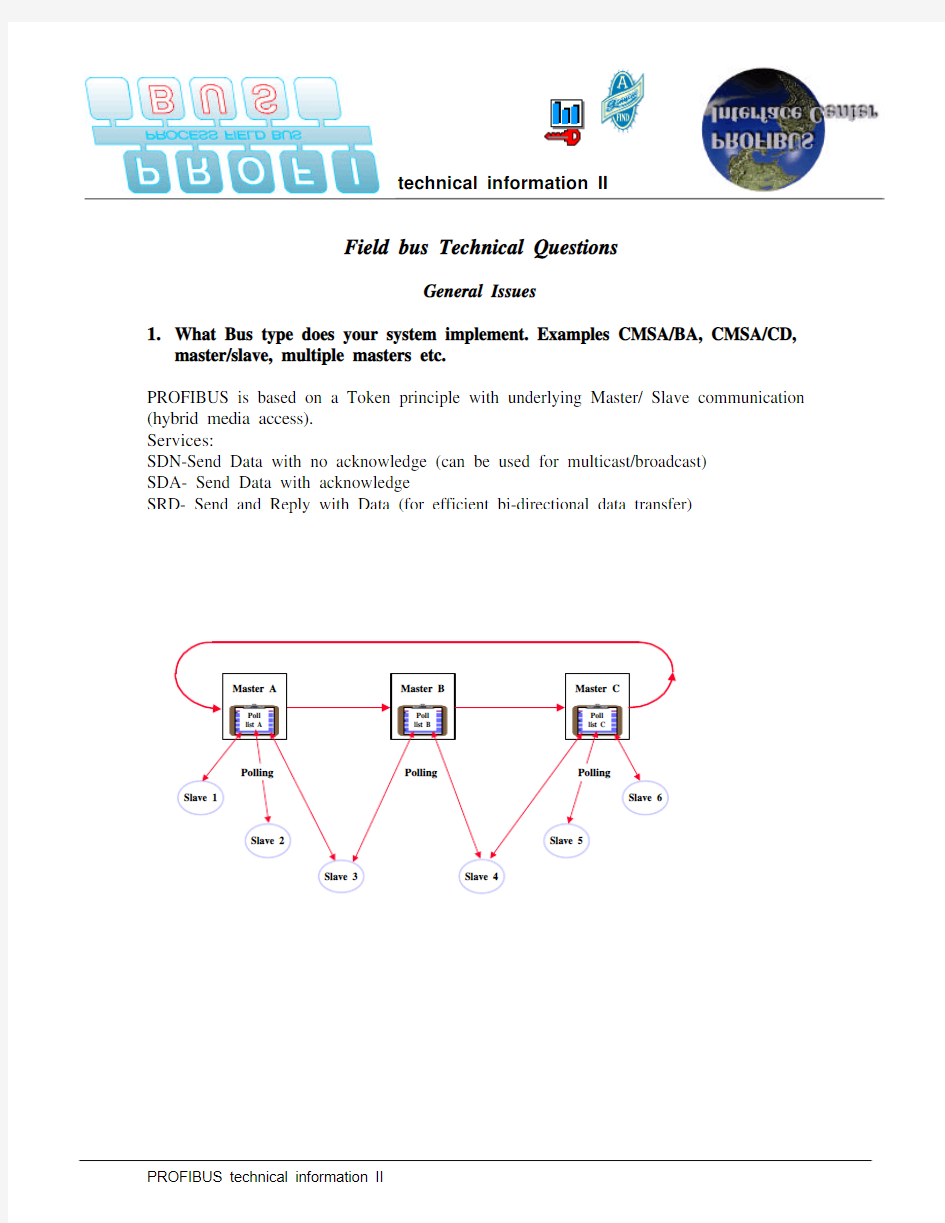
PROFIBUS is based on a Token principle with underlying Master/ Slave communication (hybrid media access).
Services:
SDN-Send Data with no acknowledge (can be used for multicast/broadcast)
SDA- Send Data with acknowledge
SRD- Send and Reply with Data (for efficient bi-directional data transfer)
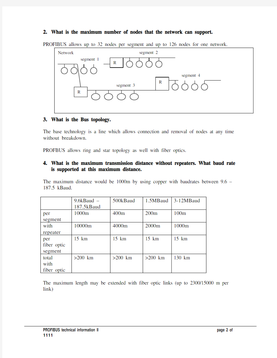
2.What is the maximum number of nodes that the network can support.
3.What is the Bus topology.
The base technology is a line which allows connection and removal of nodes at any time without breakdown.
PROFBUS allows ring and star topology as well with fiber optics.
4.What is the maximum transmission distance without repeaters. What baud rate
is supported at this maximum distance.
The maximum distance would be 1000m by using copper with baudrates between 9.6 –187.5 kBaud.
500kBaud 1.5MBaud3-12MBaud
9.6kBaud –
187.5kBaud
1000m400m200m100m
per
segment
with
10000m4000m2000m1000m
repeater
15 km15 km15 km15 km
per
fiber optic
segment
>200 km>200 km>200 km130 km
total
with
fiber optic
The maximum length may be extended with fiber optic links (up to 2300/15000 m per link)
5.What types of transmission media are used and supported.
?Copper cable (shielded twisted pair- known as IBM type 1 cable)
?solid and stranded cable
?specialized materials for plastic surrounding
?fiber optic
?in glass
?in plastic
? Infrared
6.How many bits are allocated at a node for input and output data.
PROFIBUS allows between 0 and 244 byte, determined by the device requirements for input and output each.
7.How is the bus powered.
There is no specialized bus power supply. The terminal resistors with pullup and pulldown are located at the end of the line and powered be the devices on that place. One combination is enough to run the system.
8.If the bus provides power to field devices what current level is available.
PROFIBUS PA does supply power for intrinsic safe devices connected with twisted pair. This is done according to IEC 1158-2 specification (maximum current is 120 mA per coupler for intrinsic safe operation and >300mA for non intrinsic safe operation).
9.How are node addresses set.
Two methods are supported:
?DIP switches or similar techniques
?setting of the node address via the bus connection
Any choice is possible
10.Does the bus provide duplicate address detection.
Configuration checks for duplicate addresses.
Masters will look for duplicate addresses before entering the token ring and when unexpected frames are received.
Slave must be set up with their ident-number and with their configuration. In case of a mismatch, this will be reported to the masters application.
11.Does the bus provide an address attendance check after the first scan.?through a so called live list
?scanning of configured slaves is done cyclic
?scanning for new masters is executed all time
12.Does the bus provide a node configuration check after the first scan.
Yes, with the function config_check after power up.
In addition, the ident number is also checked.
13.Does the bus provide error detection and correction algorithms.
PROFIBUS has a variety of error detection capabilities
?Checkbits in every byte
?Checksum for every message
?Startdelimiters for efficient frame detection
?Addressing information (source and destination)
?Inactivity detection to find out the beginning
?Transmitter check at the master devices
?Monitoring the token passing procedures
?The error correction is done by retries.
?PROFIBUS includes message duplication capabilities
14.Can a node provide parameter programming. Examples logic inversion and
similar Boolean operations. Explain any extended detection.
There are several ways for parameter setup:
?PROFIBUS allows the individual set of parameters (a maximum of 237 Bytes) during the startup
?Acyclic exchange of parameters at runtime.
?Parameter load from a PC by a second master
15.What I/O granularity does the Bus support.
?The minimum is one byte
?The granularity is determined by the device
?Integer, unsigned, floating point, string and structures of the base types are possible.? A node may have IO-modules with the granularity of one bit.
?There are various links available connecting subordinated bit-level busses (i.e. AS-I)
16.What minimum address space allocation does the bus provide.
This is determined by the device, the minimum would be one byte.
17.What is the cost per point of an AC input/output and a DC input/output.
Include the most cost efficient implementation as well as the cost to add a single bit of I/O as a node to the network.
DC input and output is about ......$ list price per channel for ET200M cards.
AC input and output is about ......$ list price per channel for ET200M cards.
The list price of a small node is approx. .......$ for ET200L but this unit has 16 Inputs onboard
18.What is the protocol efficiency of this Bus.
The protocol efficiency may be up to 70%.
The configurations mentioned in the performance metrics section have a efficiency of 40%. This figures are configuration dependent.
19.Does the Bus support multiple protocols.
?PROFIBUS FMS,
?DP
?DP extensions
may use the same link and may be implemented in one node
20.How many vendors support this technology.
Latest number the PTO provided is a membership of 800
with more than 1600 different devices.
21.What form factors are supported for network scanner cards.
?For Personal computers: PCI, PCMCIA, PC 104 ISA and VME.
?All known PLCs at moderate size may be equipped with PROFIBUS cards (including AB, Modicon, GE, Mitsubishi)
?Various other solutions are offered
22.What governing body controls this standard. Are changes to the specification
immediately released to all 3rd party vendors.
PROFIBUS is controlled through PROFIBUS International and presented through 20 organizations worldwide. Every add on or change will be defined within the different working groups(18 groups are registered now), every member can participate in the various working groups. All specifications must be released by the Board and are available for all members and non member.
The working groups are initiated and controlled by the technical committees and the board.
Example:
The following e-mail was sent on 10-9-98 to all PTO members:
To members of a Regional PROFIBUS Association:
Call for Experts
Specification of new features of the Fieldbus Data Link Layer for PROFIBUS
The working group "Technique" within the technical committee
"standardization" will start evaluation of new functionality’s for the
PROFIBUS Data Link Layer soon. The new functions will be specified driven
by new application areas (Motion Control as well as Power Plant). These new
functions will include:
=B7 Equidistancy
=B7 Slave - to - Slave communication (Publisher / Subscriber model)
=B7 Time synchronization
All members of any regional PROFIBUS user group worldwide are permitted and
invited to join the working group "Technique"
Please contact Dr. Haehniche (e-mail: haeh@ifak.fhg.de) if you are
interested.
Best regards
PROFIBUS International - Technical Support Centre
Michael Volz
Installation, Diagnostics and Commissioning
1.What diagnostic systems are in place to verify proper drop and node
connections.
?Several diagnostic tools are available which allow to measure the bus and connectors for proper installation.
? A simple electric meter will do it for most cases (a segment unpowered has a resistance of 110 to 130 Ohms for midrange cable length).
2.Can the Bus be enabled in segments to minimize troubleshooting requirements.?Segmenting can be done by use of repeaters or optical link modules.
?Step-by-Step start up can be done through the connectors by using the integrated termination.
3.What high level tools are available for network diagnostics.
Every PROFIBUS Master allows detailed diagnostic function within the application ?Diagnostic information of each individual slave(Type of Slave, availability, various status information)
?Diagnostic overview of all slaves
?Master Diagnostic information
?statistic counter
Service engineers can use a bus monitor which allows to trace the bus.
?Monitoring all data
?Hardware filtering mechanism
?Time stamps
?Trigger conditions
?Special events
?
4.Can a network configuration be restored remotely.
?Network download protocol is defined in the standard
?Some System have proprietary protocols to prevent inconsistencies (network configuration and PLC configuration are NOT independent)
5.Does the Bus provide tools for throughput monitoring enabling the user to check
the validity of various node configurations.
?Various configuration tools offer such a functionality as well the bus monitor.?Most users look on reaction time rather than cycle time which includes the PLC scan.
6.Are diagnostic counters local to a node or are they a distributed function.
?Usually this information is available within the master (PLC or PC)- the field devices often do not know about errors in transactions.
?There is a diagnostic in every slave, which will be reported to the master and the application..
7.With the standard diagnostic tools what kind of MTTD (mean time to diagnose)
for network faults should the user expect to see using this bus. Elaborate on any special capabilities.
?Errors are reported immediately.
?Worst case 2 cycles is the maximum delay to transport diagnostic to the master.
(regarding the figures below, this is less than 2,2ms/13,4ms at 12Mbaud/1.5Mbaud).?Every other actions and their duration is application dependant. If your system has a backup strategy for that error the bus topology helps to run even in the presence of an error.
8.Does the bus support any kind of hot swap capability.
?PROFIBUS allows replacing of devices without interrupting the bus traffic to connected nodes.
?Slave devices need not be reconfigured in case of a switching in the masters role.
9.Can nodes be exercised to verify the field device connections with a hand held
programmer or personal computer.
?Hand held and PC software is available to do this.
?Typically this feature is used for startup or trouble shooting.
? A diagnostic device can be connected to the bus without any specific change in the masters or slaves parameter.
10.Can nodes be configured to autorestart after the removal of a node or network
fault.
?The reaction of a device error is application specific.
?One option is to continue operation.
?After replacement of a node the new node is automatically reinserted.
Performance Metrics
1.How long would it take to update a network with 16 nodes of 256 digital I/O
(4096 total points).
? 1.09ms by 12MBaud
?6,71ms by 1.5MBaud.
2.What is the best and worst case repeatability of this configuration.
?The best case which is 99% the normal case is that the timing is absolute stable (5% jitter is possible due to control functions)
?In case of a failure (stations are dropping out) the timing can change ? 1 transmission failure will be corrected within 500/100μs (1,5/12Mbaud)
? 1 station failure will add a jitter of 700/300μs
? A worst case scenario of 33ms by 1.5MBaud or 6.6ms by 12MBaud for one cycle will occur when all stations fail (in this situation the reactiontime is meaningless).?After the failure detection the timing is back to the regular cycle time.
3.How long would it require to update a network with 256 analog I/O points.(16
bit words)
It is exactly the same time as under 1., PROFIBUS makes no difference in the format. 256 words is equal to 4096 I/O points. I’m assuming that we have 256 words in each direction, 256 input words and 256 output words. A difference can occur in your master station. The PLC or PC might make a difference in calculating I/O or analog values. PROFIBUS makes no difference.
4.What is the best and worst case repeatability of this device configuration.
The same as mentioned under 2.
5.How would loss of the token change the determinism of network
communications. For systems that do not use a token passing mechanism explain how a communication fault is recovered from and its impact on determinism.
?There is no token loss in monomaster systems
?Token loss in multiple masters are almost impossible
? A Master breakdown while using the token may produce this fault.
The recovery time in this situation is 1.6 ms at 1.5Mbaud and 0.67ms at 12 MBaud.
6.Can the Bus support change of state signaling.
If a device changes the state of an input PROFIBUS can recognize it with the planned extension for the future (see e-mail from Mr. Volz – PI).
7.How well will this implementation scale with respect to improvements in raw bit
rate transmission.
?There is a transmission speed detection in almost every slave device as well as repeaters. This will enable the user to change the Baudrate by simply changing it at the masters site.
?PROFIBUS has enhanced transmission speed 2 times. there is no problem with the various devices because all functions may run at a basic configuration.
8.Can portions of the network be scanned more frequently than the entire system.
? A change of the cyclic list is possible, however due to the fast cycle it is not necessary in typical applications. There is a possibility to send low frequent cyclic messages as acyclic messages.
9.Is message prioritization implemented.
PROFIBUS defines 2 message priorities,
an application prioritization is only possible within FMS.
10.Can larger consecutive blocks of data be moved using block transfer.
Yes, with all protocols.
Competitive Advantage
1.What attributes of you system qualify as a best in class product.
Deterministic, speed, ease to use, acceptance, support, diagnostic, multi protocols,
PROFIBUS offers a great flexibility. This enables the application engineer to make his design without counting bits and bytes. One byte more is less than 1μs! Error recovery will be done quickly without user interaction.
It easy to integrate PROFIBUS in field devices.
PROFIBUS is a very robust protocol with outstanding error handling capabilities.
PROFIBUS-DP allow transmission of IO-Data with short reaction time this include transportation from IO to the bus and from the bus to the application.
PROFIBUS-DP can be configured without specific communication knowledge. The device model is exactly what matters in remote IO.
PROFIBUS DP is what the user needs(see below)
------------------------------------------------------------------------------------------------------------------
From: timli@https://www.doczj.com/doc/ac11879133.html,
One of the FAQ questions regards the strengths of Profibus, and this is a subject close to my heart.
To my mind the key strength of Profibus DP over other contending fieldbuses is its great simplicity (despite the efforts of some of the Siemens software. I have seen and used to complicate things!), particularly the main competitor, DeviceNet.
The basic data exchange and wiring principles for Profibus DP can be readily explained in 15 minutes to PLC programmers and plant electricians without recourse to software engineering jargon. Network administration is trivial.
This is vital first to build confidence in the technology, and then to allow it to be applied painlessly by customers not having wide experience of networks. The scan model is very close to that already used on a PLC backplane, and there is really nothing new to learn: even comms wiring, biasing, and bus termination is straightforward and inexpensive.
By contrast DeviceNet, in which I had an involvement until quite recently, is hugely complex, using a formal (but somewhat deficient, in my view, since there is neither C++ style inheritance nor IEC1131 style execution model) object model, connections, and a plethora of options when setting up and running a network, which I think were due to compromises caused by the standardisation process. If you know what you are doing (which implies a software
engineering/network background and a dedicated comms specialist) it is wonderful, since you can set up highly efficient peer to peer networks that do exactly the job required. On the other hand if you have just one day to get the comms for a project going, you are probably going to have to do some headscratching, and I would probably put a lot of strong coffee into my project budget... Large companies with R&D departments concerned with automation technology will be able to cope, but I suspect that smaller customers will struggle. Furthermore there is no equivalent of the SPC3 to tie implementations together and provide a basic level of conformancy, particularly at the low end (S&S Tech have something quite close in their object code module, and of course there is ABs group 2 only slave(*) source code which no-one is supposed to use but of course everyone does).
I don't want to rubbish DeviceNet, because a great deal of it is technically excellent. But I do think it is likely to become the 'Betamax' equivalent in Device level networks unless really good config tools are produced that fully provide the expertise needed to plan, commission and run the network.
Armin and I had a discussion in the sci.engr.control newsgroup (probably available via
https://www.doczj.com/doc/ac11879133.html,) which covered this ground as well as some other subjects, and which I thought was quite interesting. Might be worth a look.
Tim Linnell
Eurotherm Controls (Note that the views expressed are personal do not necessarily reflect those of Eurotherm)
(*) Try explaining to a plant electrician what a group 2 only slave is and why its UCMM services must be proxied, and you will know exactly why I think Profibus is simpler! In fact, a good way of selling DP against DeviceNet is to do two back-to-back 10 minute technical explanations of the two protocols to non specialist plant technicians.
南阳理工学院控制仪表及装置结课论文 学院(系):机械与汽车工程学院专业:测控技术与仪器 学生:梁梓鸣 指导教师:李珍 完成日期2014年12月
南阳理工学院控制仪表及装置结课论文 现场总线总结报告 Field-bus Summary Report 总计:毕业设计(论文)11 页 表格:0 个 插图: 10 幅
南阳理工学院控制仪表及装置结课论文 现场总线总结报告 Fieldbus Summary Report 学院(系):机械与汽车工程学院 专业:测控技术与仪器 学生姓名:梁梓鸣 学号:1302314011 指导教师(职称):李珍(高级工程师) 评阅教师: 完成日期:2014年12月 南阳理工学院 Nan yang Institute of Technology
现场总线总结报告 测控技术与仪器梁梓鸣 [摘要]现场总线是指以工厂内的测量和控制机器间的数字通讯为主的网络,也称现场网络。也就是将传感器、各种操作终端和控制器间的通讯及控制器之间的通讯进行特化的网络。现场总线的产生对工业的发展起着非常重要的作用,对国民经济的增长有着非常重要的影响。现场总线逐渐在工业现场推广,不少设备不但具有传统仪表的功能,而且还具备现场总线的功能、在DCS中,现场总线被广泛应用。 [关键词]现场总线;网络;通讯 Fieldbus Summary Report Measurement & Control Technology and Instruments Major LIANG Zi-ming Abstract:Fieldbus refers to the factory focuses on the digital communication between the measurement and control of the machine in the network,also called field network.Is the sensor, various operating terminal and communication between the controller and the controller communication between specialized network.Fiedbus production plays a very important role to the development of industry,have a very important impact on the growth of the national economy. Fieldbus is gradually popularized in industrial field,a lot of equipment not only has the function of the traditional instrument,but also has the function of fieldbus,in the DCS,fieldbus is widely used. Key words:Fieldbus;network;communication
测控技术与测控网络系统 (论文) 题目:PROFIBUS 2013年 5月4日 P R O F I B U S
摘要 PROFIBUS是面向工厂自动化和流程自动化的一种国际性的现场总线标准。它已被广泛应用于制造业自动化(汽车制造,装瓶系统,仓储系统)、过程自动化(石油化工,造纸和纺织品工业企业)、楼宇自动化(供热空调系统)、交通管理自动化、电子工业和电力输送等行业。在可编程控制器、传感器、执行器、低压电器开关等设备之间传递数据信息。 关键词: PROFIBUS,网络化测控系统,现场总线,总线存取 一.当前网络化测控系统的现状和发展趋势: 测控技术的两个方面,一个是测一个是控。“测”是依靠传感器和信号传输电路,即测控电路;“控”则是依靠现代计算机的计算处理能力,根据数据得出相应结果,
通过反馈等方式控制整个系统。计算机已经成为测控技术中的中坚力量,于是,网络技术也就自然而然的越来越成为测控技术满足实际需求的关键支持。但是不可否认,测控电路依然是测控技术发展的基础,和另一个重要的发展方向。 目前,应用较多的现代控制策略主要有自适应控制、变结构控制、鲁棒控制和预测控制等。就应用而言,现代测控技术在当今社会的各个行业中,起着举足轻重的作用。其中,现场仪表与控制室装置之间通信采用模拟信号4~20mA,数字控制仪表内部的信号处理为数字信号,但输入仍为4~20mA,控制装置之间和控制装置与上位计算机之间采用数字通信技术。例如目前数字控制仪表,DCS系统,PLC系统,FCS系统等。 从20世纪80年代中期以来,CIMS日渐成为制造工业的热点,原因在于CIMS是在新的生产组织原理和概念指导下形成的一种新型生产模式。大规模及超大规模集成电路的发展,提高了计算机的可靠性和性能价格比,从而使计算机控制系统的应用也越来越广泛。随着现代科学技术以及复杂自动控制系统和信息处理与技术的提高,现代检测技术将朝着检测结果高精度、系统智能化、检测结果数字化、检测功能多元化、检测器件微型化、检测系统自动化的放向发展,它将广泛应用于工业、农业、家庭、医学、军事和空间科学技术等许多科学领域。测量单元微小型化、智能化测量控制与仪器仪表大量采用新的传感器、大规模和超大规模集成电路、计算机及专家系统等信息技术产品,不断向微小型化、智能化发展,从目前出现的“芯片式仪器仪表”,“芯片实验室”、“芯片系统”等看,测量单元的微小型化和智能化将是长期发展趋势。从应用技术看,微小型化和智能化测量单元的嵌入式连接和联网应用技术得到重视。测控范围向立体化、全球化扩展,测量控制向系统化、网络化发展。随着仪器仪表所测控的既定区域不断向立体化、全球化甚至星球的发展,仪器仪表和测控装置向测控装置系统化、网络化方向发展。例如卫星测控系统,运载火箭上配置的各种传感器就达到数千,而卫星上各种测控装置构成一个完整的自动测控系统,然后和多个地面站的测控系统构成一个广域测控系统。 二.现场总线简介: 1、基金会现场总线(FF).FF分低速H1和高速H2两种通信速率,前者传输速率为 31.25Kbit/秒,通信距离可达1900m,可支持总线供电和本质安全防爆环境。后者传
PROFIBUS现场总线 Abstract: PROFIBUS is an international, open and equipment vendor independent standard for field bus communication. It is widely used in manufacturing automation, process industrial automation and buildings, transportation, electricity and other areas of automation. This article focuses on domestic and international developments in PROFIBUS, its technical characteristics, its technical advantages and prospects in automation control area. Keyword: field bus, open control system, PROFIBUS;PROFIBUS-DP;PROFIBUS-PA;PROFIBUS-FMS;IEC61158;EN50170 standard;RS-485 一.概述 随着计算机、控制、通信和网络等技术的进步,现场总线在20世纪80年代中期逐渐发展起来。现场总线是应用在生产现场测量与控制设备之间实现双向串行多节点数字通信的系统,也被称为开放式、数字化、多节点通信的底层控制网络。PROFIBUS是过程现场总线(ProcessField Bus)的缩写。德国科学技术部总结了20世纪80年代德国工业界自动控制技术的发展经验,为了适应分散控制系统的发展要求,对各公司自己定义的网络协议加以规范化、公开化,使得不同厂家生产的自动控制设备在网络通信级互相兼容、遵守同一协议,以利于提高工业标准化水平,于1987年列为德国国家项目,由13家大公司(如SIEMENS、ABB、AEG等)及5家研究所经过2年多的时间完成。1991年,PROFIBUS成为德国国家标准DIN
现场总线论文 题目:现场总线的现状及其发展趋势班级:电子1302 学号:1310910215 姓名:李天德
摘要: 现场仪表与控制室仪表之间的数字通信统称为现场总线。现场总线技术自20世纪90年代出现以来已成为世界范围内自动化技术发展的热点之一,广泛用于过程自动化、制造自动化、楼宇自动化等领域的现场智能设备互连通讯网络。它作为工厂数字通信网络的基础,沟通了生产过程现场及控制设备之间及其与更高控制管理层次之间的联系,被誉为“自动化仪表与控制系统的一次变革”。我国自20世纪90年代后期即开始引入并研究总线技术,将其作为今后工业过程控制技术研究的重点,并于1996年正式将现场总线技术的研究和产品.开发列入九五国家重点科技攻关项目。 Digital communication between field instruments and control room instrumentation are collectively referred to as fieldbus. Fieldbus technology since the 1990 s has become a worldwide one of the hotspots for the development of automation technology, is widely used in process automation, manufacturing automation, building automation and other fields of field intelligent device interconnection communication network. It as the basis of factory of digital communication network, communication between the scene of the production process and control devices and the connection between the higher control management level, is known as the "automation instrument and control system of a change". Since the late 1990 s in our country started to introduce and study bus technology, and use it as a focus in the study of industrial process control technology in the future, and in 1996 formally to fieldbus technology research and product. The development in the ninth national key scientific research projects. 关键词:现场总线、数字通讯、集散系统 Keywords: field bus, digital communication, distributed systems
用PROFIBUS-DP现场总线控制 ACS800系列变频器的方法 北京迪安帝科贸有限公司曲冬辉 摘要:文章详细介绍了ACS800系列变频器在PROFIBUS-DP现场总线控制系统中的参数设置,数据格式和控制方法。 关键词:PROFIBUS 现场总线 ACS系列变频器 引言 现场总线技术已成为世界自动化技术的热点,近年来在我国工业自动化系统中已受到关注并推广应用。PROFIBUS-DP是现场总线PROFIBUS中广泛应用的一种协议、主要用于现场级的主从通信,实现现场级控制系统与分布式I/O及其他现场级设备之间的通信(它有极好的抗电磁干扰性能)。由于Siemens公司对PROFIBUS现场总线的大力推广以及其在国内的影响力,我国工业自动化系统已广泛应用了PROFIBUS-DP现场总线。 ABB公司的ACS系列变频器由于其优异的性能,在各个行业得到大量应用。本文以ACS800系列变频器为例,详细介绍用PROFIBUS-DP现场总线系统控制ACS800系列变频器的方法,希望对广大工程技术人员有所帮助。一.PROFIBUS-DP现场总线控制器(如PLC或DCS系统)的设置: 1.安装ABB变频器GSD文件 ABB_0812.GSD; 2.在系统PROFIBUS-DP硬件配置中添加从站ABB Drives RPBA-01,站号为2(或其它站号),插入PPO Type Module为4; 3.在2号从站的参数设置中,将Operation Mode改为Vendor Specific(即ABB传动协议); 4.其它为默认配置; 5.将配置下载到主站中。 6.这样主站对从站2的输出区(OUTPUT)的数据结构为: Output:含义: 第一个字用于ABB传动通信协议的控制字CW 第二个字变频器的给定值REF1 第三个字变频器的给定值REF2 第四个字变频器的给定值REF3(由ACS800变频器参数90.01决定)第五个字变频器的给定值REF4(由ACS800变频器参数90.02决定)第六个字变频器的给定值REF5(由ACS800变频器参数90.03决定)7.主站对从站2的输入区(INPUT)的数据结构为: Input:含义: 第一个字用于ABB传动通信协议的状态字SW 第二个字变频器的实际值ACT1(由ACS800变频器参数92.02决定)第三个字变频器的实际值ACT2(由ACS800变频器参数92.03决定)第四个字变频器的实际值ACT3(由ACS800变频器参数92.04决定)第五个字变频器的实际值ACT4(由ACS800变频器参数92.05决定)第六个字变频器的实际值ACT5(由ACS800变频器参数92.06决定)
PROFIBUS-DP现场总线的结构及应用 Profibus 的最大优点在于具有稳定的国际标准EN50170 作保证,并经实 际应用验证具有普遍性。目前已广泛应用于制造业自动化、流程工业自动化和 楼宇、交通电力等领域。 Profibus 由3 个兼容部分组成,即PROFIBUS-DP(Decentralized Periphery,分布I/O 系统)、PROFIBUS-PA(Process Automation,现场总线信息规范)和PROFIBUS-FMS(Fieldbus Message Specification,过程自动化)。 PROFIBUS-DP 是一种高速、低成本通信,专门用于设备级控制系统与分散 式I/O 的通信。使用PROFIBUS-DP 可取代24V DC 或4~20mA 信号传输。PORFIBUS-PA 专为过程自动化设计,可使传感器和执行机构连在一根总线上, 并有本质安全规范。PROFIBUS-FMS 用于车间级监控网络,是一个令牌结构的 实时多主网络。 1.PROFIBUS 的协议结构PROFIBUS 协议结构是根据ISO7498 国际标准,以OSI 作为参考模型的。PROFIBUS-DP 定义了第1、2 层和用户接口。第3 到7 层未加描述。用户接口规定了用户及系统以及不同设备可调用的应用功能, 并详细说明了各种不同PROFIBUS-DP 设备的设备行为。PROFIBUS-FMS 定义了第1、2、7 层,应用层包括现场总线信息规范(FMS)和低层接口(LLI)。FMS 包括了应用协议并向用户提供了可广泛选用的强有力的通信服务;LLI 协 调不同的通信关系并提供不依赖设备的第2 层访问接口。PROFIBUS-PA 的数 据传输采用扩展的PROFIBUS-DP 协议。另外,PA 还描述了现场设备行为的 PA 行规。根据IEC1157-2 标准,PA 的传输技术可确保其本质安全性,而且可 通过总线给现场设备供电。使用连接器可在DP 上扩展PA 网络。2.PROFIBUS 的传输技术PROFIBUS 提供了三种数据传输型式:RS-485 传
河海大学常州校区 毕业设计(论文) 年级专业12级机电一体化技术 学生姓名许旸 指导教师朱丹青 评卷人 教学地点常州冶金技师学院 年月日
摘要 作为自动化领域的热点之一,现场总线己成为自动化系统与分散的现场设备间信息交换的主要技术。PROFIBUS是国际上应用十分广泛的工业过程现场总线,主要应用于加工自动化、过程自动化、楼宇自动化等领域。 文章从结合所研究的水厂的实际需要出发,将先进的现场总线技术、以太网技术与传统的机械电气技术相结合,并应用到水厂控制系统的实际设计过程中。在电气控制系统的设计过程中,采用了上位机加下位机的设计模式,组建了远程集中控制与现地控制相结合的控制网络。上位机选用功能强大的工控组态软件——组态王和操作方便灵活的触摸屏。下位机则采用可靠性高的可编程控制器和先进的PROFIBUS现场总线完成对现场设备的控制。 关键词:可编程控制器,现场总线,PROFIBUS-DP,监控系统
The ControlSystem Based on Fieldbus Abstract Nowadays, the technology of Fieldbus has become the hotspot in the research field of automation and become the main method of communication and exchange of information in the DCS systems. And the Profibus is a kind of Fieldbus broadly used in many situations of process control of industry such as automation of processing, automation of machining and automation of building. According to the actuality of the studied water station, the thesis combine the advanced Fieldbus technique,Ethernetand the traditionalmachine andelectric technique together, and use them to design the supervise controlling system of the water station. During the designing of the electricity control system, the thesis used the mode that made up of monitor system and control system, formatted a network thatiscombinedbyfarconcentratescontrolsystemandnearlycontrol system. The monitor system chooses the functional monitoring software—the king monitor and the man-machine interface, which operated conveniently. And the control system chooses dependablyprogrammablelogiccontrollerandadvanceProfibus Fieldbus to completely control the spot equipments. Keyword:PLC, Fieldbus,PROFIBUS-DP,Supervise Controlling System
现场总线及Profibus应用 1 引言 随着网络技术的不断发展,因特网正在把全世界的计算机系统、通信系统逐渐集成起来,形成信息高速公路,从而形成一个公用的数据网络。以计算机(Computer)、通信(Communication)和控制(Control)为代表的“3C”技术迅速发展,使得网络集成信息自动化正在迅速应用到现场设备、控制、管理和市场的各个层次,并迅速进入工业制造、工业流程、环境工程、民用工程等应用领域。[1] 而现场总线(Fieldbus)作为当今自动化领域技术发展的热点之一,被誉为自动化领域的计算机局域网。它的出现,标志着工业控制领域又一个新时代的开始,并将对该领域的发展产生重要影响。 2 现场总线 2.1 现场总线的产生背景 随着控制、计算机、通讯、网络等技术的发展,信息交换沟通的领域正在迅速覆盖从工厂的现场设备层到控制、管理的各个层次、覆盖从工段、车间、工厂、企业乃至世界各地的市场。信息技术的飞速发展,引起了自动化系统结构的深刻变革,现场总线就是在这种形式下发展起来的新技术。[1] 20世纪50年代至今,工业过程控制仪表一只采用4~20mA的标准信号。 20世纪60年代,测控系统一般采用直接数字式控制系统。 20世纪70年代,数字式计算机被映入到测控系统中,此时的计算机提供的是集中式控制处理。 20 世纪80 年代,微处理器被嵌入到各种仪器设备中,而形成了分布式控制系统(DCS),这种分布式控制系统经历了若干发展阶段,从集散控制系统(DCS)、现场总线控制系统( FCS) 到智能控制、维护、管理集成系统(ICMMS),控制单元日益智能化,控制的方式日益走向多智能控制单元的协同工作模式[2]。 由于各种现场总线技术的相继出现,人们对传统的模拟仪表和控制系统要求变革的呼声越来越高,现场总线为引入智能现场仪表提供了一个开放平台。基于现场总线的分布式控制系统(Fieldbus Control System, FCS)是在传统的分布式控制系统(Distributed Control System, DCS)的基础之上发展起来的,顺应了自动控制系统发展的潮流。 2.2 现场总线的基本概念 按照国际电工委员会IEC61158的标准定义,现场总线是安装在制造或过程区域的现场装置与控制室内的自动空盒子装置之间的数字式、串行、多点通信的数据总线[1]。它的本质含义主要表现在以下三个方面:现场总线是一种低带宽的计算机局域网;现场总线是一种数字通信协议;现场总线是开放式、数字化、多点通信的底层控制网络。图1为DCS与FCS 的对比。
现场总线(PROFIBUS)技术简介 摘要: 本文详细的介绍PROFIBUS的概念以及相关的基础知识。 内容: 第一章:现场总线技术及PROFIBUS 1.1 现场总线技术的由来 1.1.1 CIMS体系结构及工业数据结构的层次划分 根据工厂管理、生产过程及功能要求,CIMS体系结构可分为5层,即工厂级、车间级、单元级、工作站级和现场级。简化的CIMS则分为3层,即工厂级、车间级和现场级。在一个现代化工厂环境中,在大规模的工业生产过程控制中,工业数据结构同样分为这三个层次,与简化的网络层次相对应。如图1-1所示。 图1-1:简化的CIMS网络体系结构
1.1.2 现场级与车间级自动化监控及信息集成是工厂自动化及CIMS不可缺少的重要部分。 现场级与车间级自动化监控及信息集成系统主要完成底层设备单机控制、连机控制、通信连网、在线设备状态监测及现场设备运行、生产数据的采集、存储、统计等功能,保证现场设备高质量完成生产任务,并将现场设备生产及运行数据信息传送到工厂管理层,向工厂级MIS系统数据库提供数据。同时也可接受工厂管理层下达的生产管理及调度命令并执行之。因此,现场级与车间级监控及信息集成系统是实现工厂自动化及CIMS系统的基础。 1.1.3 传统的现场级与车间级自动化监控及信息集成系统 传统的现场级与车间级自动化监控及信息集成系统(包括:基于PC、PLC、DCS 产品的分布式控制系统),其主要特点之一是,现场层设备与控制器之间的连接是一对一(一个I/O点对设备的一个测控点)所谓I/O接线方式,信号传递4-20mA(传送模拟量信息)或24VDC(传送开关量信息)信号。如图1-2所示: 图1-2:传统的现场级与车间级自动化监控及信息集成系统 1.1.4 系统主要缺点 (1)信息集成能力不强:控制器与现场设备之间靠I/O连线连接,传送4-20mA 模拟量信号或24VDC等开关量信号,并以此监控现场设备。这样,控制器获取信息量有限,大量的数据如设备参数、故障及故障纪录等数据很难得到。底层数据不全、信息集成能力不强,不能完全满足CIMS系统对底层数据的要求。 (2)系统不开放、可集成性差、专业性不强:除现场设备均靠标准4-20mA/24VDC连接,系统其它软、硬件通常只能使用一家产品。不同厂家产品之间缺乏互操作性、互
PROFIBUS现场总线 摘要 现场总线技术是20世纪90年代兴起的一种集控制技术、仪表技术和计算机网络技术为一体的先进的工业控制技术。这其中PROFIBUS现场总线是目前较为流行的五种现场总线中较为有仪表性的一种。与其它现场总线系统相比,PROFIBUS的最大优点在于具有稳定的国际标准EN50170作保证,并经实际应用验证具有普遍性。目前已应用的领域包括加工制造、过程控制和楼宇自动化等。PROFIBUS的开放性和不依赖于厂商的通信设想,已在10多万成功应用中得以实现。市场调查确认,在德国和欧洲市场中PROFIBUS占开放性工业现场总线系统的市场份额超过40%。 一、现场总线 1.1 现场总线的产生背景 随着控制、计算机、通讯、网络等技术的发展,信息交换沟通的领域正在迅速覆盖从工厂的现场设备层到控制、管理的各个层次、覆盖从工段、车间、工厂、企业乃至世界各地的市场。信息技术的飞速发展,引起了自动化系统结构的深刻变革,现场总线就是在这种形式下发展起来的新技术。 20世纪50年代至今,工业过程控制仪表一只采用4-20mA的标准信号。20世纪60年代,测控系统一般采用直接数字式控制系统。 20世纪70年代,数字式计算机被映入到测控系统中,此时的计算机提供的是集中式控制处理。 20世纪80年代,微处理器被嵌入到各种仪器设备中,而形成了分布式控制系统(DCS),这种分布式控制系统经历了若干发展阶段,从集散控制系统(DCS)、现场总线控制系统(FCS)到智能控制、维护、管理集成系统(ICMMS),控制单元日益智能化,控制的方式日益走向多智能控制单元的协同工作模式。 由于各种现场总线技术的相继出现,人们对传统的模拟仪表和控制系统要求变革的呼声越来越高,现场总线为引入智能现场仪表提供了一个开放平台。基于现场总线的分布式控制系统(Fieldbus Control System,FCS)是在传统的分布式
(作业)封面 题目 Profibus现场总线技术综述 专业电子科学与技术 入学年月 2013.9 PROFIBUS现场总线技术综述
摘要:PROFIBUS是一种国际性现场总线标准,本文从PROFIBUS总线的形成、技术参数和特点、应用以及发展前景等几个方面进行阐述。并阐述了PROFIBUS在系统集成方面的应用,具体说明了PROFIBUS在工厂自动化系统中的位置以及PROFIBUS控制系统的组成,分析了其应用领域。 关键字:PROFIBUS ;现场总线;控制系统 Review of PROFIBUS field bus technology Abstract: Profibus as an international fieldbus standard, this article state the formation of PROFIBUS field bus, technical parameters and characteristics, application and development prospect. It expounds the application of PROFIBUS in the aspect of system integration, the concrete expression of PROFIBUS in factory automation system of location and composition of PROFIBUS control system, and analyzes its application field. Key words: Profibus;Fieldbus;Control system 0引言 现场总线(Fieldbus)是20世纪80年代末、90年代初国际上发展形成的,用于过程自动化、制造自动化、楼宇自动化等领域的现场智能设备互连通讯网络。自上世纪80年代以来, 有几种类型的现场总线技术己经发展成熟, 它们是CAN、LONWORKS、PROFIBUS、WORLDFIP、HART、FF现场基金会总线等。PROFIBUS(Process Fieldbus的缩写)是一种国际化的、开放的、不依赖于设备生产商的现场总线标准,它广泛应用于制造业自动化、流程工业自动化和楼宇、交通、电力等其他自动化领域。 1 形成 PROFIBUS技术的发展经历了如下过程: (1)1984 年,美国仪表协会(ISA)下属的标准与实施组工作中的ISA/SP50 开始制订现场总线的标准。 (2)1985 年国际电工委员会决定由Proway Working group 负责现场总线体系结构与标准的研究工作。(3)1986 年德国开始制订过程现场总线(process field-bus)标准,简称PROFIBUS,由此拉开了现场总线标准制订和产品开发的序幕. (4)1987年由德国SIEMENS公司等13家企业和5家研究机构联合开发; (5)1989年成为德国工业标准DIN19245; (6)1996年成为欧洲标准EN50170V.2(PROFIBUS-FMS-DP); (7)1998年PROFIBUS-PA被纳入EN50170V.2; (8)1999年PROFIBUS成为国际标准IEC61158的组成部分 (TYPEIII); (9)2001年成为中国的机械行业标准JB/T10308-3-2001; (10)2006年成为中国的国家标准GB/T20540-2006。 2 PROFIBUS 现场总线系统的技术参数与特点 2.1PROFIBUS通信模型和协议类型
关于现场总线的论文 目前,较为流行的现场总线有FF、LonWorks、Profibus、WorldFIP、CAN、HART(过渡协议)等,这些现场总线和过渡协议在我国(主要是北京)都有了代表处或挂靠单位,并且大多数都有不同程度的开发和应用。其中FF和HART列入"九五"攻关项目,参加现场总线智能仪表的研究开发单位主要有:西安仪表集团、上海工业自动化仪表研究所、重庆工业自动化仪表研究所、上海自动化仪表股份公司、重庆川仪集团、北京华控技术公司等,专门攻克HART协议和FF协议通信软硬件技术难关。 1.开发的产品主要有: 1)HART变送器(包括智能温度变送器、智能压力变送器、智能流量变送器); 2)HART智能电动执行机构; 3)HART网桥; 4)现场设备管理系统软件; 5)FF现场总线和CAN总线园卡、接口等 HART的攻关任务已基本完成,今年就可验收。FF的攻关明年上半年可完成并验收。 目前,较流行的现场总线中,FF、Profibus、LonWorks、CAN\HART协议书籍报刊上介绍的比较多,其中HART和LonWorks在我国开发和应用较多。下面只简单介绍一下WorldFIP的情况。 2.WorldFIP:WorldFIP现场总线不论高速还是低速,只有一套通信协议,可以不需要任何网桥或网关,低速与高速的衔接只用软件完成。 WorldFIP组织认为,它的生产者/使用者(Producer/Consumer)模式和总线仲裁器(BUSAr-biter)的调度方式特别适合工业过程控制的现场总线系统。它的很多优点都与此有关。FF与IEC标准草案都采用了这种通信模式,只是名称不同。FF称为发布方/接收方(Publi-sher/Subscriber)与链接调度器(LAS),实际方式与WorldFIP基本一致。这也说明了为什么WorldFIP支持IEC标准,因为他们向IEC靠拢在技术上是比较容易的。 目前,WorldFIP的应用领域为:输电、铁路运输、地铁、化工、空间技术、汽车制造等。1998年5月,WorldFIP组织在中国建立了技术推广中心,并把注意力放在中国的能源和铁路两个将大力发展的领域。 现场总线的技术基础是一种全数字化、双向、多站的通信系统,是应用于各种计算机控制领域的工业总线,因现场总线潜在着巨大的商机,世界范围内的各大公司投入相当大的人力、物力、财力来进行开发研究。当今现场总线技术一直是国际上各大公司激烈竞争的领域,由于现场总线技术的不断创新,过程控制系统由第四代的DCS发展至今的FCS(Fieldbus Control System)系统,已被称为第五代过程控制系统。而FCS和DCS的真正区别在于其现场总线技术。现场总线技术以数字信号取代模拟信号,在3C(Computer计算机、Control控制、Commcenication通信)技术的基础上,大量现场检测与控制信息就地采集、就地处理、就地使用,许多控制功能从控制室移至现场设备。由于国际上各大公司在现场总线技术这一领域的竞争,仍未形成一个统一的标准,目前,在现场总线网络互联都是遵守OSI参考模型。
Field bus Technical Questions General Issues 1.What Bus type does your system implement. Examples CMSA/BA, CMSA/CD, master/slave, multiple masters etc. PROFIBUS is based on a Token principle with underlying Master/ Slave communication (hybrid media access). Services: SDN-Send Data with no acknowledge (can be used for multicast/broadcast) SDA- Send Data with acknowledge SRD- Send and Reply with Data (for efficient bi-directional data transfer)
2.What is the maximum number of nodes that the network can support. 3.What is the Bus topology. The base technology is a line which allows connection and removal of nodes at any time without breakdown. PROFBUS allows ring and star topology as well with fiber optics. 4.What is the maximum transmission distance without repeaters. What baud rate is supported at this maximum distance. The maximum distance would be 1000m by using copper with baudrates between 9.6 –187.5 kBaud. 500kBaud 1.5MBaud3-12MBaud 9.6kBaud – 187.5kBaud 1000m400m200m100m per segment with 10000m4000m2000m1000m repeater 15 km15 km15 km15 km per fiber optic segment >200 km>200 km>200 km130 km total with fiber optic The maximum length may be extended with fiber optic links (up to 2300/15000 m per link)
PROFIBUS-DP现场总线的结构及应用newmaker Profibus的最大优点在于具有稳定的国际标准EN50170作保证,并经实际应用验证具有普遍性。目前已广泛应用于制造业自动化、流程工业自动化和楼宇、交通电力等领域。 Profibus由3个兼容部分组成,即PROFIBUS-DP(Decentralized Periphery,分布I/O系统)、PROFIBUS-PA(Process Automation,现场总线信息规范)和PROFIBUS-FMS(Fieldbus Message Specification,过程自动化)。 PROFIBUS-DP是一种高速、低成本通信,专门用于设备级控制系统与分散式I/O的通信。使用PROFIBUS-DP可取代24V DC或4~20mA 信号传输。PORFIBUS-PA专为过程自动化设计,可使传感器和执行机构连在一根总线上,并有本质安全规范。PROFIBUS-FMS用于车间级监控网络,是一个令牌结构的实时多主网络。 1.PROFIBUS的协议结构 PROFIBUS协议结构是根据ISO7498国际标准,以OSI作为参考模型的。PROFIBUS-DP定义了第1、2层和用户接口。第3到7层未加描述。用户接口规定了用户及系统以及不同设备可调用的应用功能,并详细说明了各种不同PROFIBUS-DP设备的设备行为。PROFIBUS-FMS定义了第1、2、7层,应用层包括现场总线信息规范
(FMS)和低层接口(LLI)。FMS包括了应用协议并向用户提供了可广泛选用的强有力的通信服务;LLI协调不同的通信关系并提供不依赖设备的第2层访问接口。PROFIBUS-PA的数据传输采用扩展的PROFIBUS-DP协议。另外,PA还描述了现场设备行为的PA行规。根据IEC1157-2标准,PA的传输技术可确保其本质安全性,而且可通过总线给现场设备供电。使用连接器可在DP上扩展PA网络。 2.PROFIBUS的传输技术 PROFIBUS提供了三种数据传输型式:RS-485传输、IEC1157-2传输和光纤传输。 (1)RS-485传输技术 RS-485传输是PROFIBUS最常用的一种传输技术,通常称之为H2。RS-485传输技术用于PROFIBUS-DP与PROFIBUS-FMS。 RS-485传输技术基本特征是:网络拓扑为线性总线,两端有有源的总线终端电阻;传输速率为9.6kbps~12Mbps;介质为屏蔽双绞电缆,也可取消屏蔽,取决于环境条件;不带中继时每分段可连接32个站,带中继时可多到127个站。 RS-485传输设备安装要点:全部设备均与总线连接;每个分段上最多可接32个站(主站或从站);每段的头和尾各有一个总线终端电阻,确保操作运行不发生误差;两个总线终端电阻必须一直有电源;当分段站超过32个时,必须使用中继器用以连接各总线段,串联的中继器一般不超过4个;传输速率可选9.6kbps~12Mbps,一旦设备
PROFIBUS现场总线 摘要: profibus是一种国际化的、开放的、不依赖于设备生产厂商的现场总线标准。它广泛适用于制造业自动化、流程工业自动化和楼宇、交通、电力等领域自动化。本文主要就profibus的国内外发展动态、技术特性、在控制领域的技术优势及应用前景进行了讨论。 关键词:现场总线;开放控制系统;profibus;profibus-dp;profibus-pa;profibus-fms;iec61158;en50170标准;rs-485; 中图分类号:tu976+.2文献标识码:a 文章编号: abstract: profibus is an international, open and equipment vendor independent standard for field bus communication. it is widely used in manufacturing automation, process industrial automation and buildings, transportation, electricity and other areas of automation. this article focuses on domestic and international developments in profibus, its technical characteristics, its technical advantages and prospects in automation control area. keyword: field bus, open control system, profibus;profibus-dp;profibus-pa;profibus-fms;iec61158;en50170 standard;rs-485 一.概述 随着计算机、控制、通信和网络等技术的进步,现场总线在20
PROFIBUS现场总线安装指导PROFIBUS Installation Guide
摘要 本文主要介绍了PROFIBUS网络中所涉及的硬件以及网络规划和安装中的注意事项,帮助用户正确的安装和使用PROFIBUS现场总线。 关键词PROFIBUS,现场总线,通讯,安装,拓扑 Key Words PROFIBUS,field bus,communication,installation,topology IA&DT Service & Support Page 2-37
目录 1PROFIBUS 概述................................Error! Bookmark not defined. 2PROFIBUS网络硬件............................Error! Bookmark not defined. 2.1PROFIBUS接口................................Error! Bookmark not defined. 2.2通讯介质 (6) 2.2.1 PROFIBUS 电缆 (6) 2.2.2光纤及接口 (8) 2.2.3PRFOBUS插头 (11) 2.2.4终端电阻 (13) 2.2.5 RS485中继器..........................................................1Error! Bookmark not defined. 2.2.6 OLM和OBT (17) 3PROFIBUS总线安装规范 (21) 3.1网络拓扑的规则 (21) 3.2 PROFIBUS网络安装的规则 (22) 3.2.1网络布线的规则 (22) 3.2.2通讯电缆的屏蔽层在电柜内的处理 (29) 3.2.3过压及雷击保护 (32) 3.2.4减小变频器等干扰源设备对通讯的影响 (33) 4PROFIBUS诊断的常用工具 (34) 5 结束语 (36) IA&DT Service & Support Page 3-37